EP2978583B1 - Verfahren zur herstellung eines kraftstofftanks oder füllrohrs und verwendung davon in einem hybridfahrzeug - Google Patents
Verfahren zur herstellung eines kraftstofftanks oder füllrohrs und verwendung davon in einem hybridfahrzeug Download PDFInfo
- Publication number
- EP2978583B1 EP2978583B1 EP14713483.7A EP14713483A EP2978583B1 EP 2978583 B1 EP2978583 B1 EP 2978583B1 EP 14713483 A EP14713483 A EP 14713483A EP 2978583 B1 EP2978583 B1 EP 2978583B1
- Authority
- EP
- European Patent Office
- Prior art keywords
- mold
- reinforcement
- sheet
- fibrous reinforcement
- thermoplastic material
- Prior art date
- Legal status (The legal status is an assumption and is not a legal conclusion. Google has not performed a legal analysis and makes no representation as to the accuracy of the status listed.)
- Active
Links
Images




Classifications
-
- B—PERFORMING OPERATIONS; TRANSPORTING
- B60—VEHICLES IN GENERAL
- B60K—ARRANGEMENT OR MOUNTING OF PROPULSION UNITS OR OF TRANSMISSIONS IN VEHICLES; ARRANGEMENT OR MOUNTING OF PLURAL DIVERSE PRIME-MOVERS IN VEHICLES; AUXILIARY DRIVES FOR VEHICLES; INSTRUMENTATION OR DASHBOARDS FOR VEHICLES; ARRANGEMENTS IN CONNECTION WITH COOLING, AIR INTAKE, GAS EXHAUST OR FUEL SUPPLY OF PROPULSION UNITS IN VEHICLES
- B60K15/00—Arrangement in connection with fuel supply of combustion engines or other fuel consuming energy converters, e.g. fuel cells; Mounting or construction of fuel tanks
- B60K15/03—Fuel tanks
- B60K15/03177—Fuel tanks made of non-metallic material, e.g. plastics, or of a combination of non-metallic and metallic material
-
- B—PERFORMING OPERATIONS; TRANSPORTING
- B29—WORKING OF PLASTICS; WORKING OF SUBSTANCES IN A PLASTIC STATE IN GENERAL
- B29C—SHAPING OR JOINING OF PLASTICS; SHAPING OF MATERIAL IN A PLASTIC STATE, NOT OTHERWISE PROVIDED FOR; AFTER-TREATMENT OF THE SHAPED PRODUCTS, e.g. REPAIRING
- B29C49/00—Blow-moulding, i.e. blowing a preform or parison to a desired shape within a mould; Apparatus therefor
- B29C49/20—Blow-moulding, i.e. blowing a preform or parison to a desired shape within a mould; Apparatus therefor of articles having inserts or reinforcements ; Handling of inserts or reinforcements
-
- B—PERFORMING OPERATIONS; TRANSPORTING
- B25—HAND TOOLS; PORTABLE POWER-DRIVEN TOOLS; MANIPULATORS
- B25J—MANIPULATORS; CHAMBERS PROVIDED WITH MANIPULATION DEVICES
- B25J15/00—Gripping heads and other end effectors
- B25J15/06—Gripping heads and other end effectors with vacuum or magnetic holding means
- B25J15/0616—Gripping heads and other end effectors with vacuum or magnetic holding means with vacuum
-
- B—PERFORMING OPERATIONS; TRANSPORTING
- B25—HAND TOOLS; PORTABLE POWER-DRIVEN TOOLS; MANIPULATORS
- B25J—MANIPULATORS; CHAMBERS PROVIDED WITH MANIPULATION DEVICES
- B25J19/00—Accessories fitted to manipulators, e.g. for monitoring, for viewing; Safety devices combined with or specially adapted for use in connection with manipulators
-
- B—PERFORMING OPERATIONS; TRANSPORTING
- B29—WORKING OF PLASTICS; WORKING OF SUBSTANCES IN A PLASTIC STATE IN GENERAL
- B29C—SHAPING OR JOINING OF PLASTICS; SHAPING OF MATERIAL IN A PLASTIC STATE, NOT OTHERWISE PROVIDED FOR; AFTER-TREATMENT OF THE SHAPED PRODUCTS, e.g. REPAIRING
- B29C49/00—Blow-moulding, i.e. blowing a preform or parison to a desired shape within a mould; Apparatus therefor
- B29C49/02—Combined blow-moulding and manufacture of the preform or the parison
- B29C49/04—Extrusion blow-moulding
- B29C49/04102—Extrusion blow-moulding extruding the material continuously
-
- B—PERFORMING OPERATIONS; TRANSPORTING
- B29—WORKING OF PLASTICS; WORKING OF SUBSTANCES IN A PLASTIC STATE IN GENERAL
- B29C—SHAPING OR JOINING OF PLASTICS; SHAPING OF MATERIAL IN A PLASTIC STATE, NOT OTHERWISE PROVIDED FOR; AFTER-TREATMENT OF THE SHAPED PRODUCTS, e.g. REPAIRING
- B29C49/00—Blow-moulding, i.e. blowing a preform or parison to a desired shape within a mould; Apparatus therefor
- B29C49/02—Combined blow-moulding and manufacture of the preform or the parison
- B29C49/06905—Using combined techniques for making the preform
- B29C49/0691—Using combined techniques for making the preform using sheet like material, e.g. sheet blow-moulding from joined sheets
-
- F—MECHANICAL ENGINEERING; LIGHTING; HEATING; WEAPONS; BLASTING
- F16—ENGINEERING ELEMENTS AND UNITS; GENERAL MEASURES FOR PRODUCING AND MAINTAINING EFFECTIVE FUNCTIONING OF MACHINES OR INSTALLATIONS; THERMAL INSULATION IN GENERAL
- F16L—PIPES; JOINTS OR FITTINGS FOR PIPES; SUPPORTS FOR PIPES, CABLES OR PROTECTIVE TUBING; MEANS FOR THERMAL INSULATION IN GENERAL
- F16L9/00—Rigid pipes
- F16L9/12—Rigid pipes of plastics with or without reinforcement
- F16L9/133—Rigid pipes of plastics with or without reinforcement the walls consisting of two layers
-
- B—PERFORMING OPERATIONS; TRANSPORTING
- B29—WORKING OF PLASTICS; WORKING OF SUBSTANCES IN A PLASTIC STATE IN GENERAL
- B29C—SHAPING OR JOINING OF PLASTICS; SHAPING OF MATERIAL IN A PLASTIC STATE, NOT OTHERWISE PROVIDED FOR; AFTER-TREATMENT OF THE SHAPED PRODUCTS, e.g. REPAIRING
- B29C49/00—Blow-moulding, i.e. blowing a preform or parison to a desired shape within a mould; Apparatus therefor
- B29C49/20—Blow-moulding, i.e. blowing a preform or parison to a desired shape within a mould; Apparatus therefor of articles having inserts or reinforcements ; Handling of inserts or reinforcements
- B29C2049/2017—Blow-moulding, i.e. blowing a preform or parison to a desired shape within a mould; Apparatus therefor of articles having inserts or reinforcements ; Handling of inserts or reinforcements outside the article
-
- B—PERFORMING OPERATIONS; TRANSPORTING
- B29—WORKING OF PLASTICS; WORKING OF SUBSTANCES IN A PLASTIC STATE IN GENERAL
- B29C—SHAPING OR JOINING OF PLASTICS; SHAPING OF MATERIAL IN A PLASTIC STATE, NOT OTHERWISE PROVIDED FOR; AFTER-TREATMENT OF THE SHAPED PRODUCTS, e.g. REPAIRING
- B29C49/00—Blow-moulding, i.e. blowing a preform or parison to a desired shape within a mould; Apparatus therefor
- B29C49/20—Blow-moulding, i.e. blowing a preform or parison to a desired shape within a mould; Apparatus therefor of articles having inserts or reinforcements ; Handling of inserts or reinforcements
- B29C2049/2021—Inserts characterised by the material or type
- B29C2049/2065—Inserts characterised by the material or type for reinforcing specific areas of the final blow moulded article
-
- B—PERFORMING OPERATIONS; TRANSPORTING
- B29—WORKING OF PLASTICS; WORKING OF SUBSTANCES IN A PLASTIC STATE IN GENERAL
- B29C—SHAPING OR JOINING OF PLASTICS; SHAPING OF MATERIAL IN A PLASTIC STATE, NOT OTHERWISE PROVIDED FOR; AFTER-TREATMENT OF THE SHAPED PRODUCTS, e.g. REPAIRING
- B29C49/00—Blow-moulding, i.e. blowing a preform or parison to a desired shape within a mould; Apparatus therefor
- B29C49/20—Blow-moulding, i.e. blowing a preform or parison to a desired shape within a mould; Apparatus therefor of articles having inserts or reinforcements ; Handling of inserts or reinforcements
- B29C2049/2073—Means for feeding the inserts into the mould, preform or parison, e.g. grippers
-
- B—PERFORMING OPERATIONS; TRANSPORTING
- B29—WORKING OF PLASTICS; WORKING OF SUBSTANCES IN A PLASTIC STATE IN GENERAL
- B29C—SHAPING OR JOINING OF PLASTICS; SHAPING OF MATERIAL IN A PLASTIC STATE, NOT OTHERWISE PROVIDED FOR; AFTER-TREATMENT OF THE SHAPED PRODUCTS, e.g. REPAIRING
- B29C49/00—Blow-moulding, i.e. blowing a preform or parison to a desired shape within a mould; Apparatus therefor
- B29C49/20—Blow-moulding, i.e. blowing a preform or parison to a desired shape within a mould; Apparatus therefor of articles having inserts or reinforcements ; Handling of inserts or reinforcements
- B29C2049/2095—Means for preparing or treating the inserts, e.g. cutting, deforming, heating, cooling or applying adhesives
-
- B—PERFORMING OPERATIONS; TRANSPORTING
- B29—WORKING OF PLASTICS; WORKING OF SUBSTANCES IN A PLASTIC STATE IN GENERAL
- B29C—SHAPING OR JOINING OF PLASTICS; SHAPING OF MATERIAL IN A PLASTIC STATE, NOT OTHERWISE PROVIDED FOR; AFTER-TREATMENT OF THE SHAPED PRODUCTS, e.g. REPAIRING
- B29C49/00—Blow-moulding, i.e. blowing a preform or parison to a desired shape within a mould; Apparatus therefor
- B29C49/02—Combined blow-moulding and manufacture of the preform or the parison
- B29C49/06905—Using combined techniques for making the preform
- B29C49/0691—Using combined techniques for making the preform using sheet like material, e.g. sheet blow-moulding from joined sheets
- B29C49/06914—Using combined techniques for making the preform using sheet like material, e.g. sheet blow-moulding from joined sheets using parallel sheets as a preform
-
- B—PERFORMING OPERATIONS; TRANSPORTING
- B29—WORKING OF PLASTICS; WORKING OF SUBSTANCES IN A PLASTIC STATE IN GENERAL
- B29K—INDEXING SCHEME ASSOCIATED WITH SUBCLASSES B29B, B29C OR B29D, RELATING TO MOULDING MATERIALS OR TO MATERIALS FOR MOULDS, REINFORCEMENTS, FILLERS OR PREFORMED PARTS, e.g. INSERTS
- B29K2023/00—Use of polyalkenes or derivatives thereof as moulding material
- B29K2023/04—Polymers of ethylene
- B29K2023/06—PE, i.e. polyethylene
- B29K2023/0608—PE, i.e. polyethylene characterised by its density
- B29K2023/065—HDPE, i.e. high density polyethylene
-
- B—PERFORMING OPERATIONS; TRANSPORTING
- B29—WORKING OF PLASTICS; WORKING OF SUBSTANCES IN A PLASTIC STATE IN GENERAL
- B29K—INDEXING SCHEME ASSOCIATED WITH SUBCLASSES B29B, B29C OR B29D, RELATING TO MOULDING MATERIALS OR TO MATERIALS FOR MOULDS, REINFORCEMENTS, FILLERS OR PREFORMED PARTS, e.g. INSERTS
- B29K2105/00—Condition, form or state of moulded material or of the material to be shaped
- B29K2105/06—Condition, form or state of moulded material or of the material to be shaped containing reinforcements, fillers or inserts
- B29K2105/08—Condition, form or state of moulded material or of the material to be shaped containing reinforcements, fillers or inserts of continuous length, e.g. cords, rovings, mats, fabrics, strands or yarns
- B29K2105/0872—Prepregs
- B29K2105/089—Prepregs fabric
-
- B—PERFORMING OPERATIONS; TRANSPORTING
- B29—WORKING OF PLASTICS; WORKING OF SUBSTANCES IN A PLASTIC STATE IN GENERAL
- B29K—INDEXING SCHEME ASSOCIATED WITH SUBCLASSES B29B, B29C OR B29D, RELATING TO MOULDING MATERIALS OR TO MATERIALS FOR MOULDS, REINFORCEMENTS, FILLERS OR PREFORMED PARTS, e.g. INSERTS
- B29K2105/00—Condition, form or state of moulded material or of the material to be shaped
- B29K2105/25—Solid
- B29K2105/253—Preform
- B29K2105/256—Sheets, plates, blanks or films
-
- B—PERFORMING OPERATIONS; TRANSPORTING
- B29—WORKING OF PLASTICS; WORKING OF SUBSTANCES IN A PLASTIC STATE IN GENERAL
- B29L—INDEXING SCHEME ASSOCIATED WITH SUBCLASS B29C, RELATING TO PARTICULAR ARTICLES
- B29L2031/00—Other particular articles
- B29L2031/712—Containers; Packaging elements or accessories, Packages
- B29L2031/7172—Fuel tanks, jerry cans
-
- B—PERFORMING OPERATIONS; TRANSPORTING
- B60—VEHICLES IN GENERAL
- B60K—ARRANGEMENT OR MOUNTING OF PROPULSION UNITS OR OF TRANSMISSIONS IN VEHICLES; ARRANGEMENT OR MOUNTING OF PLURAL DIVERSE PRIME-MOVERS IN VEHICLES; AUXILIARY DRIVES FOR VEHICLES; INSTRUMENTATION OR DASHBOARDS FOR VEHICLES; ARRANGEMENTS IN CONNECTION WITH COOLING, AIR INTAKE, GAS EXHAUST OR FUEL SUPPLY OF PROPULSION UNITS IN VEHICLES
- B60K15/00—Arrangement in connection with fuel supply of combustion engines or other fuel consuming energy converters, e.g. fuel cells; Mounting or construction of fuel tanks
- B60K15/03—Fuel tanks
- B60K2015/03032—Manufacturing of fuel tanks
-
- B—PERFORMING OPERATIONS; TRANSPORTING
- B60—VEHICLES IN GENERAL
- B60K—ARRANGEMENT OR MOUNTING OF PROPULSION UNITS OR OF TRANSMISSIONS IN VEHICLES; ARRANGEMENT OR MOUNTING OF PLURAL DIVERSE PRIME-MOVERS IN VEHICLES; AUXILIARY DRIVES FOR VEHICLES; INSTRUMENTATION OR DASHBOARDS FOR VEHICLES; ARRANGEMENTS IN CONNECTION WITH COOLING, AIR INTAKE, GAS EXHAUST OR FUEL SUPPLY OF PROPULSION UNITS IN VEHICLES
- B60K15/00—Arrangement in connection with fuel supply of combustion engines or other fuel consuming energy converters, e.g. fuel cells; Mounting or construction of fuel tanks
- B60K15/03—Fuel tanks
- B60K2015/03486—Fuel tanks characterised by the materials the tank or parts thereof are essentially made from
- B60K2015/03493—Fuel tanks characterised by the materials the tank or parts thereof are essentially made from made of plastics
Definitions
- the present invention firstly relates to a method for manufacturing a fuel tank
- hybrid engines There is a general principle of operation for hybrid engines which consists in operating either the electric motor or the heat engine, or both at the same time depending on the model.
- the fuel tanks of these engines are generally pressurized (typically, to a pressure of the order of 300 - 400 mbar) to limit the load on the canister, which is generally done by a functional element located after the ventilation valves, called FTIV (Fuel Tank Isolation Valve).
- FTIV Fluel Tank Isolation Valve
- This element includes a safety valve (calibrated to the maximum operating pressure of the tank) and an electric pilot to be able to bring the tank to atmospheric pressure before filling. It follows that these tanks must have, compared to the fuel tanks of traditional heat engines, improved mechanical strength, in particular in the case of plastic tanks.
- the solution currently on the market consists of a very thick metal tank, which considerably increases the weight of the tank and thus increases fuel consumption and exhaust gas emissions.
- the publication WO 2012 / 031705A2 contemplates an alternative of replacing the fabric of reinforcing fibers with a composite semi-finished product containing reinforcing fibers.
- This finished product includes holes which are traversed by the molten material from the parison to provide mechanical attachment. To obtain an effective mechanical anchoring, it is necessary that the material of the parison flows through the holes in sufficient quantity to form kinds of rivets on the other side of the reinforcement.
- This technique of the prior art may be difficult to carry out due to the viscosity of the parison.
- Another drawback of this known technique lies in the fact that it is necessary to increase the thickness of the reservoir, and therefore its weight and its cost.
- the object of the present invention is therefore to provide a new solution for fixing a fibrous reinforcement to the wall of a reservoir, which does not have the drawbacks of known solutions.
- the invention also relates to the manufacture of the filler pipes.
- a filler pipe is a conduit for conveying a liquid or a gas inside a tank.
- a filler neck may be subjected to chippings from the wheels, requiring an additional protective screen.
- This protective screen can be removed by adding local reinforcement to the tubing.
- the fixing solution proposed by the invention can be used for a filling tube.
- the invention has the additional advantage that it makes it possible to avoid any finishing operation.
- the invention makes it possible to reduce production costs, by providing a reduction in labor and a shortening of the cycle time of the production line.
- the subject of the invention is a process for welding a fibrous reinforcement to an object chosen from the assembly consisting of a manufacture of a reservoir and of a filler pipe according to claim 1.
- the invention thus provides a new fixing solution which does not have the drawbacks of known solutions.
- connection between the fibrous reinforcement and the wall namely the weld
- the connection between the fibrous reinforcement and the wall is a method of joining which does not require any mechanical restraint (namely, no three-dimensional shape which would be engaged with another complementary three-dimensional shape) but provides continuity of material between the wall and the reinforcement, which makes the connection more reliable than in known solutions, while being less bulky.
- the wall is considered to be in a molten state if at least the part thereof which is intended to be welded to the fibrous reinforcement is in a molten state.
- the rest of the wall can therefore be in any state and in particular not melted.
- the fibrous reinforcement is heated using a heating element which is placed in front of the reinforcement to heat it by radiation or by contact.
- This heating can take place in the mold, in which case the heating element must be placed near the reinforcement in the mold, or outside the mold.
- the fibrous reinforcement is heated outside the mold to bring it into a molten state, then it is introduced heated into the mold.
- This prior shaping of the reinforcement, or preforming of the reinforcement can take place on a preforming support, after heating of the reinforcement and before its transfer into the mold.
- the shaping can also take place in the mold, after heating the reinforcement.
- the shaping can also be carried out during the transfer of the reinforcement to the mold.
- the fuel for which the tank according to the invention is intended may be gasoline, diesel, a biofuel, etc. and may have an alcohol content of 0 to 100%.
- the reservoir or the tubing is made of thermoplastic material.
- thermoplastic material is meant any thermoplastic polymer, including thermoplastic elastomers, as well as their mixtures.
- polymer denotes both homopolymers and copolymers (in particular binary or ternary). Examples of such copolymers are, without limitation: random distribution copolymers, block copolymers, block copolymers and graft copolymers.
- thermoplastic polymer or copolymer whose melting point is lower than the decomposition temperature are suitable.
- Synthetic thermoplastics which exhibit a melting range of at least 10 degrees Celsius are particularly suitable.
- such materials are those which exhibit polydispersion of their molecular weight.
- polyolefins thermoplastic polyesters, polyketones, polyamides and their copolymers
- a mixture of polymers or copolymers can also be used, as can a mixture of polymeric materials with inorganic, organic and / or natural fillers such as, for example, but not limited to: carbon, clays, salts and others. inorganic derivatives, natural or polymeric fibers. It is also possible to use multilayer structures consisting of stacked and integral layers comprising at least one of the polymers or copolymers described above.
- a polymer often used is polyethylene. Excellent results have been obtained with high density polyethylene (HDPE).
- HDPE high density polyethylene
- the wall of the reservoir or of the tubing may consist of a single layer of thermoplastic material or of two layers.
- One or more other possible additional layers can, advantageously, consist of layers of liquid and / or gas barrier material.
- the nature and the thickness of the barrier layer are chosen so to limit as much as possible the permeability of liquids and gases in contact with the internal surface of the reservoir or of the tubing.
- this layer is based on a barrier resin, that is to say a resin impermeable to fuel such as EVOH, for example (ethylene-vinyl acetate copolymer partially hydrolyzed).
- the tank or the tubing can be subjected to a surface treatment (fluorination or sulfonation) with the aim of making it impermeable to the fuel.
- the reservoir or the tubing according to the invention preferably comprises an EVOH-based barrier layer located between external HDPE-based layers.
- the fibrous reinforcement in question in the present invention can be in many forms; it is generally a plate comprising both a thermoplastic material and staple fibers or long fibers or continuous fibers which may or may not be woven.
- the staple fibers have final lengths of a few tens / hundreds of microns.
- the residual lengths are a few millimeters.
- continuous fibers or continuous filaments in the case where the length of the fibers used is several tens of centimeters.
- Woven fibers are preferred. These fibers can be based on glass, carbon, a polymer (such as a polyamide, for example aromatic such as aramid), or even be natural fibers such as hemp or sisal.
- the fibers of the fibrous reinforcement according to the invention are preferably compatible with the thermoplastic material and therefore, generally, compatible with polyolefins and in particular with HDPE.
- the fibers can be sized (surface treated) with a compatibilizing substance such as a silane.
- a reactive HDPE-type binder can also be used.
- reactive functions of maleic anhydride type can advantageously be used.
- the fibrous reinforcement comprises a thermoplastic material compatible with that of the reservoir or of the tubing, or even identical to the latter.
- Compatibility means that the thermoplastic material of the fiber reinforcement and the thermoplastic material of the reservoir or tubing can weld together. They when brought into contact with each other while in a molten state.
- it is generally polyethylene and in particular HDPE.
- the fiber content in the reinforcement is preferably at most 70%, preferably at most 50%, or even at most 30%, the remainder of the reinforcement being essentially constituted by thermoplastic material.
- the thermoplastic material content of the reinforcement is at least 30%, preferably 50%, or even at least 70%.
- the thermoplastic material is preferably melted around / in the mass of fibers so as to constitute a homogeneous sheet or plate having, on at least part of its surface, thermoplastic material so that the welding is facilitated.
- the production of the reinforcement can be done by calendering, compression molding, injection molding, projection molding, or even under molding.
- the reinforcement covers at least part of an area where a component is fixed (for example: the filler neck where the filler pipe is attached) and includes a barrier layer so that it fulfills both a reinforcement function (in this often fragile zone) and a waterproofing function.
- the reinforcement is advantageously obtained by compression molding of a multilayer sheet including a barrier layer (and preferably, a sheet comprising a layer of EVOH between two layers of HDPE), of a mat of fibers (of preferably: continuous non-woven and randomly distributed glass fibers) and HDPE sheet.
- the thickness of the reinforcement is preferably between 0.1 and 2 mm.
- its modulus is preferably at least 5,000 MPa or even at least 10,000 MPa.
- This reinforcement can be combined with other techniques or reinforcement elements.
- a wall part of greater thickness and / or between at least two elements (accessories) connecting the lower and upper wall parts of the tank that is to say respectively that constituting the bottom and the roof when the tank is fitted to the vehicle.
- These elements may for example comprise the part of the interior face of the tank which is substantially vertical when the latter is mounted on the vehicle; a pump-gauge module; a bonding pad ("kiss point", or local welding of the lower and upper walls of the tank), and in particular, one of the pads described in the application WO2011054709 in the name of the applicant and incorporated by reference in the present application; and / or a hollow reinforcing pillar, optionally integrating an active function as described in the application WO2010122065 on behalf of the applicant and incorporated by reference into the present application as well.
- the mold which can be used for the manufacture of the reservoir or of the tubing in accordance with the invention can be of any kind, provided that it contributes to giving its shape to the reservoir or to the tubing.
- This mold advantageously comprises, at the location provided for the preheated reinforcement, means for maintaining the mold at a sufficiently high temperature to prevent cooling of the reinforcement before it is welded to the sheet.
- the method according to the invention can then include a step of heating the reinforcement, carried out between the moment when the reinforcement is introduced into the mold and the moment when it is welded to the wall.
- sheet is meant here a preform of molten thermoplastic material, generally extruded and having a cylindrical shape and / or in the form of flat panels and / or cylinder halves, for example.
- the reservoir or the tubing is produced by co-extrusion-blow molding.
- a continuous extrusion technique as well as an accumulation extrusion technique or a sequential extrusion technique, all techniques well known to those skilled in the art.
- the reservoir or the tubing is left to cool and this preferably to a temperature such that the dimensional stability of its wall is reached. Usually, this is essentially room temperature, a special conditioning not being necessary (unless perhaps to speed up cooling).
- a notable advantage of the invention is that the welding of the reinforcement to the wall of the reservoir or of the tubing takes place in line with the molding of the reservoir or of the tubing, whether this is during the forming of the sheet by blowing or during the post-blowing of the tank or the tubing, which brings a reduction in the production cycle time.
- the reinforcement (and optionally, the surface of its weld zone on the tank or on the pipe) is heated before carrying out the welding.
- the heating temperature will depend on the technique used. It is preferable that the temperature is high enough to ensure the melting of the thermoplastic material (eg HDPE). It is therefore necessary to bring the thermoplastic material to an appropriate temperature (for HDPE, greater than 135 ° C and preferably greater than 150 ° C, or even 180 ° C).
- An advantage of the invention is that the reinforcement is welded to the wall of the reservoir or of the pipe while said wall is still hot, as a consequence of the method of manufacturing the reservoir or of the pipe, that is to say blowing a sheet or post-blowing of the reservoir or of the tubing to cool it or it, without requiring any additional operation subsequent to these steps.
- the invention also relates to a method of manufacturing an object chosen from the assembly consisting of a fuel tank and a filler pipe, by performing a step of introducing a sheet of material.
- thermoplastic in an at least partially molten state in a blow mold, from a step of shaping the sheet to the impression of the mold by blow molding using a blowing gas and a step of mold release of the sheet, the object comprising a wall of thermoplastic material formed by said sheet and locally reinforced by a fibrous reinforcement comprising both a thermoplastic material compatible with that of the sheet and staple fibers or long fibers or continuous fibers which may or may not be woven, a method characterized in that it comprises the steps of the method described above for welding the fibrous reinforcement to the sheet, the mold of the welding method being the blow mold and the gas pressure which inflates the wall against the mold during welding being the pressure of the blow gas.
- the method for manufacturing the reservoir or tubing integrates the step of welding the fibrous reinforcement to the wall of the reservoir or the tubing without it being necessary to provide a separate welding operation.
- the blowing operation is used not only to shape the sheet, as is known, but also to weld the reinforcement to the wall of the reservoir or of the tubing.
- the attachment by welding of the reinforcement to the wall of the tank or of the tubing also provides the advantages already indicated, compared to mechanical attachment.
- the fibrous reinforcement is introduced into the mold in order to apply it against a face of the sheet opposite to the interior face of the mold.
- the reinforcement is on the face of the sheet directed towards the future interior of the reservoir or of the tubing.
- the fibrous reinforcement is introduced into the mold in order to apply it against the interior face of the mold.
- the reinforcement is located on the face of the sheet facing the future exterior of the reservoir or of the tubing.
- two sheets of thermoplastic material in an at least partially molten state are introduced into a blow mold consisting of two half-molds and a core separating the two half-molds. molds, one sheet being introduced between a first half-mold and the core, the other sheet being introduced between the second half-mold and the core, the method further comprising a step of bonding the two sheets together after their shaping, by opening the mold, removing the core from between the two half-molds and bringing the two half-molds together.
- This process is described in the published application of the applicant EP1110697 and in particular provides the advantage of allowing the integration of various components inside the tank, as soon as it is shaped by blowing. Thanks to the invention, this advantage is completed by the integration of a fibrous reinforcement on the wall of the tank taking advantage of the pressure of the blowing gas and without off-line operation of manufacturing the tank.
- the core then comprises mobile means for positioning the reinforcement close to the interior wall of the mold, making it possible to apply the reinforcement against the sheet.
- the reinforcement is therefore applied against the face of the sheet intended to constitute the interior face of the reservoir.
- the invention also relates to a method of manufacturing an object chosen from the assembly consisting of a fuel tank and a filler neck, by performing a step of demolding a sheet in a state. at least partially melted out of a blow mold in which it has been shaped, a step of introducing the sheet into a post-blowing mold and a step of inflating the sheet against the wall of the mold post-blowing using a post-blowing gas, the object comprising a wall of thermoplastic material formed by said sheet and locally reinforced by a fibrous reinforcement comprising both a thermoplastic material compatible with that of the sheet and staple fibers or long fibers or continuous fibers which may or may not be woven, a method characterized in that it comprises the steps of the method of welding the fibrous reinforcement to the sheet described above, the welding mold being the mold post-blowing and the pressure of the gas which inflates the wall against the mold being the pressure of the post-blowing gas.
- advantage is taken of the pressure of the post-blowing gas to weld the fibrous reinforcement to the wall still in the molten state of the reservoir or of the tubing.
- the operation is always carried out online, without any additional operation on the reservoir or the tubing, outside its production line.
- the pressure for applying the reinforcement against the weld zone is therefore exerted by direct mechanical contact. (contact pressure) by using the blowing or post-blowing gas, which is generally compressed air.
- the positioning of the reinforcement in the mold can be achieved by means of a fibrous reinforcement gripper comprising both a thermoplastic material and staple fibers or long fibers or continuous fibers which may or may not be woven, for the manufacture of fuel tanks or filler pipes comprising a wall of thermoplastic material formed by said sheet and locally reinforced by such a fibrous reinforcement, the thermoplastic material of which is compatible with that of the sheet, the gripper being intended to be moved by a robot or by a jack fixed on a core of the mold, where appropriate, for positioning the fibrous reinforcement in the mold and being equipped with retaining means such as for example suction cups, preferably metallic, and with means for heating the reinforcement.
- retaining means such as for example suction cups, preferably metallic
- the reinforcement positioned in the mold can be held there in position by holding means, for example suction means through the wall of the mold.
- the sheet is provided with at least one zone resistant to compression included at least in part in the weld zone of the reinforcement, in order to be able to withstand the force associated with the pressure exerted during welding.
- the welding of the reinforcement on the tank or the tubing does not necessarily have to be carried out over its entire surface.
- the welding takes place over substantially the entire surface, that is to say, at least 90% of it, even ideally 100%.
- the fibrous reinforcement is preformed to a predetermined three-dimensional shape by a tool for shaping a fibrous reinforcement, comprising an oven for heating said reinforcement to a temperature sufficient to bring it into a molten state, and an imprint to conform the reinforcement in the molten state into a predetermined three-dimensional shape.
- the impression of the shaping tool comprises two jaws which can move apart for insertion of the reinforcement and come closer for shaping of the reinforcement, one of these two jaws being movable in a given direction (not necessarily rectilinear, for example circular) and provided with means for gripping the shaped reinforcement.
- the gripping means are provided with an air suction system.
- the two jaws of the shaping tool are movable, however only one is provided with gripping means.
- the imprint for conforming the reinforcement in the molten state is a support, for example a grid, of the predetermined three-dimensional shape, on which the reinforcement rests under its own weight.
- one of the two jaws of the impression of the shaping tool consists of a set of parallel plates arranged perpendicular to the direction of approach of the two jaws and having, facing the 'other jaw of the imprint, the edges forming a conformation ply of the reinforcement.
- the web is close to the final shape that the reinforcement will have after molding.
- Such an imprint has the advantage that the oven and the forming tool can be separated and that the reinforcement can be transferred from one to the other by being carried by a grid, the bars of which are inserted between the parallel plates to deposit said reinforcement on the sheet formed by the edges of said parallel plates.
- the oven comprises means making it possible to heat the reinforcement on its two faces.
- the present application also discloses a mold as described above, in all its variants and in particular a blow mold consisting of two half-molds and a core separating the two half-molds.
- the disclosure also relates to a core of such a mold, comprising movable means for positioning the reinforcement near the interior wall of the mold.
- the present disclosure also relates to a reservoir or a pipe capable of being obtained by a method as described above and comprising a wall made of thermoplastic material and a fibrous reinforcement welded onto at least part of its external surface, this fibrous reinforcement comprising a plastic of the same nature or compatible with that of the outer surface of the reservoir or of the tubing, and continuous woven fibers. They are preferably glass fibers as described above.
- the preferred variants described above in the context of the method according to the invention apply to the reservoir or to the tubing according to the invention.
- the present disclosure also relates to the use of a tank (obtained by a process) as described above as a fuel tank of a hybrid vehicle.
- This tank can also be used on a conventional vehicle, where the reinforcing effect obtained can be put to good use to avoid having to resort to the metal straps generally used to prevent creep of the lower wall of the tank when the latter is fixed to the bottom of the tank. vehicle body.
- the presence of the reinforcement could also make it possible to reduce the thicknesses of the reservoir giving rise to a reduction in weight and an increase in useful volume. In the case of the tubing, the presence of the reinforcement makes it possible to avoid the addition of a protective anti-gravel screen.
- the reinforcing effect obtained by the subject of the disclosure can be combined with the use of other known reinforcements such as straps, gluing pads, internal reinforcements (rods, partitions), overmolded fabrics. ... mentioned above and any other type of reinforcement, both internal and external (especially since the first type helps to obtain a zone resistant to compression).
- the combination of the invention with these known techniques make it possible to reduce the size and / or the quantity of re-bonding pads, internal reinforcements (rods, partitions), overmolded fabrics, etc.
- the weight of the final solution is minimal and the useful volume of the reservoir is maximum.
- the application of the fibrous reinforcement against the face of the sheet opposite the impression of the mold is carried out using a mobile element, carried by a robot external to the mold or by a core of the mold. mold (when the blow mold is made of two shells and a core separating the two half-molds).
- FIG. 1 there is shown, in vertical section, two shells 1 and 1 'facing an open mold for the manufacture of a fuel tank.
- Each shell 1, 1 ' has here a simple shape with flat perpendicular walls, connected by fillets, but any hollow shape is possible.
- an extrusion die 5 provided with a forming tool 6 makes it possible to produce a tubular sheet or parison 4 just above the mold, while the two shells 1, 1 'are spaced apart from one another. the other.
- a tubular parison one could of course use two flat parisons, or sheets, for example according to the method described in EP1110697 .
- plane and tubular denote objects whose shape is generally and approximately plane, respectively tubular.
- the actual extrusion conditions of the sheet are such that the latter inevitably exhibits irregularities in shape which prevent it from being strictly of the intended geometric shape.
- Two reinforcements 3 and 3 ' were preheated and introduced into the mold, placing them one on a fillet of the internal surface of one of the shells 1', the other 3 'on a flat part of the internal surface of the other shell 1.
- the positioning of the reinforcement 3, on a non-planar zone, requires the shaping of this reinforcement. This shaping may have taken place beforehand in a shaping tool or be carried out in the mold, by precise application of the reinforcement against the internal wall of the shell, at the appropriate location of this shell.
- a means for maintaining each reinforcement in position against the wall of the shell is also provided.
- This means can be an air suction through a channel provided for this purpose in the shell or a mechanical maintenance (for example using claws or rods, through or not), the edge outer or middle of the reinforcement.
- a length of parison 4 equivalent to the height of the mold was also lowered, either during the positioning of the reinforcements, or before or after.
- the mold is then closed by bringing its two shells 1, 1 'together, as seen in the figure 2 .
- the parison is clamped at its lower end between the two shells and at the exit of the extrusion head 5 between the two shells and the forming tool 6.
- the blowing of the parison is then started, by injecting air into its interior under a pressure varying from 5 to 10 bars, depending on the dimensions of the mold.
- the air pressure applies the parison against the walls of the shells 1 and 1 'and brings the parison to the geometry of the tank during manufacture.
- the air pressure has the additional effect of pressing the molten parison against the molten reinforcements held in the mold. This results in a weld of the reinforcements on the parison.
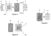
- Figure 4 Loading of the reinforcement 3 on a grid 10 by an operator 12.
- This grid comprises a succession of metal bars 10A parallel in one direction. It is mounted on a rail (not shown) and advances automatically towards an oven 14 after loading.
- the bars of the grid must allow reinforcement 3 to be lifted from below. To do this, the bars must have an appropriate spacing to properly support the reinforcement, including when it has reached a molten state.
- Figure 5 Heats the reinforcement in the oven 14.
- the two faces of the reinforcement are heated simultaneously, to reduce the cycle time.
- Figure 6 Once the heating is complete, the grid on which the reinforcement is located comes out of the oven and is positioned in an indentation of a 3D shaping tool 16, in order to conform the reinforcement in the molten state in a three-dimensional shape.
- the shell of the shaping tool constitutes a preforming support and comprises two jaws, one lower 18A, movable vertically, the other upper 18B, as seen in the figure. figure 7 .
- the upper jaw 18B fulfills a second function: it is a gripper. This gripper 18B is placed above the reinforcement.
- Figure 8 The lower jaw 18A comes to press on the lower face of the reinforcement and compresses it against the gripper 18B. This operation conforms the reinforcement to the desired three-dimensional shape.
- the lower jaw 18A consists of vertical plates 18C which slide between the bars 10A of the grid on which the reinforcement 3 rests.
- the plates have upper edges forming a layer (imaginary and materialized on the figure 7 by a broken line) which coincides with the three-dimensional shape that it is desired to give to the reinforcement.
- retaining rods are mounted on jacks (not shown) and prevent the reinforcement from sliding between the jaws when they close, by keeping it in place during this closure.
- a reinforcement of dimensions 340mmX109mm two jacks with a diameter of 3mm are sufficient to ensure that the position is maintained.
- the stroke of the cylinders is adjusted so as to apply sufficient pressure on the reinforcement without damaging it.
- the location of this retention is preferably located in the area of the first contact during the closing of the jaws.
- Figure 9 Taking of the shaped reinforcement in three dimensions by a robot 22 carrying the gripper 18B under partial vacuum.
- the vacuum is preferably obtained by a Venturi type system.
- the vacuum level is adjusted so as not to generate excessive deformation of the reinforcement.
- the inventors have observed that a vacuum of -266 mbar allows effective retention of the reinforcement on the gripper.
- orifices 24 will be used for the evacuation. Indeed, the use of a single orifice generates air flow which cools the reinforcement in the vicinity of the latter.
- the gripper may have an edge following the final shape of the reinforcement. This edge can be materialized by a flat surface a few millimeters wide.
- This edge can be coated with PTFE (or some other non-stick coating) to prevent molten deposition, which could occur over time.
- temperature regulation of the gripper makes it possible to avoid too rapid cooling of the reinforcement during transfer to the blow mold.
- a water (or oil) or electric heater regulation system installed on a metal element of the gripper makes it possible to effectively maintain the temperature of the fiber reinforcement.
- the surface of the mold in contact with the reinforcement can be equipped with suction systems (vent type, not shown).
- vents must be small enough to prevent the reinforcement from entering due to the strong pressures exerted during the blowing of the parison against the mold.
- retractable rods are placed on the surface of the mold in contact with the reinforcement. These rods pierce the reinforcement during its docking to the surface of the mold, which helps transfer the reinforcement between the gripper and the mold.
- a specific temperature regulation (higher than the average temperature of the mold) makes it possible to avoid too rapid cooling of the reinforcement (for example: zone at 60 ° C, while the rest of the mold is at 11 ° C).
- the robot thus places the reinforcement on the surface of a blow mold.
- the reservoir is blown, which causes the reinforcement to be overmolded by contact and pressure with the molten parison.
- the sheet 4 of thermoplastic material leaves the extrusion head 5 in an at least partially molten state. It penetrates between the two shells 1 and 1 ', that is to say into a blow mold consisting of these two shells and optionally of a core (not shown).
- the sheet 4 is intended to be blown into the blow mold (when the two shells have moved closer to each other) by blowing using a blowing gas.
- the movable element may for example be a jack fixed to the core.
- the movable element 30 ends in a form 32 which is here flat but, more generally, is adapted to the part of the inner face of the shell 1 against which the sheet 4 will be applied under the pressure of said form 32.
- the mobile element includes means for gripping the fibrous reinforcement which are not detailed here.
- the fiber reinforcement was previously heated to bring it into the mold in a molten state. However, this heating could take place during the transport of the reinforcement 3 by the movable element 30 or before this transport.
- An optional means 2 maintains the temperature of the region of the shell 1 adjacent to the fibrous reinforcement 3.
- the movable element 30 has the function of applying the reinforcement 3 against a face of the sheet 4 opposite the inner face of the shell 1.
- the fibrous reinforcement 3 is welded to the sheet 4 which is in an at least partially molten state.
- welding can be complete from this stage of operations.
- the weld is perfect by applying the pressure of the blowing gas to the sheet 4, during the shaping of the latter by blowing against the two shells.
- the application of the fibrous reinforcement 3 against the sheet 4 is carried out after the step of blowing the sheet 4. take place during the transport of the reinforcement 3 by the movable element 30 or before this transport.
- An optional means 2 maintains the temperature of the region of the shell 1 adjacent to the fibrous reinforcement 3.
- the movable element 30 has the function of applying the reinforcement 3 against a face of the sheet 4 opposite the inner face of the shell 1.
- the fibrous reinforcement 3 is welded to the sheet 4 which is in an at least partially molten state.
- welding can be complete from this stage of operations.
- the weld is perfect by applying the pressure of the blowing gas to the sheet 4, during the shaping of the latter by blowing against the two shells.
- the application of the fibrous reinforcement 3 against the sheet 4 is carried out after the step of blowing the sheet 4.
Landscapes
- Engineering & Computer Science (AREA)
- Mechanical Engineering (AREA)
- Manufacturing & Machinery (AREA)
- Robotics (AREA)
- General Engineering & Computer Science (AREA)
- Sustainable Energy (AREA)
- Sustainable Development (AREA)
- Chemical & Material Sciences (AREA)
- Combustion & Propulsion (AREA)
- Transportation (AREA)
- Life Sciences & Earth Sciences (AREA)
- Cooling, Air Intake And Gas Exhaust, And Fuel Tank Arrangements In Propulsion Units (AREA)
- Blow-Moulding Or Thermoforming Of Plastics Or The Like (AREA)
- Hybrid Electric Vehicles (AREA)
- Moulds For Moulding Plastics Or The Like (AREA)
Claims (13)
- Verfahren zum verschweißen einer Faserverstärkung (3, 3 ') während der Herstellung von einem Gegenstand ausgewählt aus der Gruppe bestehend aus einem Tank und einem Füllrohr, wobei der Gegenstand eine Wand (4) aus thermoplastischem Material umfasst, wobei die Faserverstärkung (3, 3') sowohl ein thermoplastisches Material, das mit dem des Objekts kompatibel ist, als auch geschnittene Fasern oder lange Fasern oder Endlosfasern, die gewebt sein können oder nicht, umfasst, wobei das Schweißverfahren die folgendenSchritte umfasst:- der Faserverstärkung (3, 3') erhitzen, um sie in einen geschmolzenen Zustand zu bringen,- in einer Form (1, 1'), das Schweißen der erwärmten Faserverstärkung (3, 3') an die Wand (4), die sich in einem zumindest teilweise geschmolzenen Zustand befindet, mittels des Drucks eines aufblasenden Gases, das die die Wand (4) gegen die Form (1, 1') aufbläst, durchführen
dadurch gekennzeichnet- Die Faserverstärkung (3, 3') in einer vorbestimmten dreidimensionalen Form vorformt wird, wobei diese Vorformung zumindest teilweise außerhalb der Form unter Verwendung eines Formwerkzeugs durchgeführt wird, das einen Ofen zum Erhitzen der Verstärkung auf eine Temperatur umfasst, die ausreicht, um sie hineinzubringen einen geschmolzenen Zustand und einen Eindruck, um die Verstärkung im geschmolzenen Zustand in die dreidimensionale vorbestimmte Form zu bringen. - Verfahren nach Anspruch 1, wobei das Objekt ein Kraftstofftank ist.
- Verfahren nach Anspruch 1, wobei das Objekt ein Füllrohr ist.
- Verfahren nach einem der vorstehenden Ansprüche, wobei die Faserverstärkung (3, 3') mit Hilfe eines Heizelements (14) erwärmt wird, das vor der Verstärkung angeordnet wird, um diese durch Strahlung, Konvektion oder Kontakt zu erwärmen.
- Verfahren nach einem der vorstehenden Ansprüche, wobei die Faserverstärkung (3, 3') außerhalb der Form erhitzt wird, um sie in einen geschmolzenen Zustand zu bringen, und dann erhitzt in die Form eingebracht wird.
- Verfahren nach dem vorstehenden Anspruch, wobei man den Schritt des Vorformens der Faserverstärkung (3, 3') auf einem Vorformträger (16) außerhalb der Form nach Erwärmung der Verstärkung (3, 3') und vor ihrer Überführung in die Form (1, 1') durchführt.
- Verfahren nach einem der vorstehenden Ansprüche, wobei der thermoplastische Gehalt der Verstärkung (3, 3') mindestens 30 %, vorzugsweise 50 %, oder mindestens 70 % beträgt.
- Verfahren nach einem der vorstehenden Ansprüche, bei dem in der Form (1, 1') an der für die vorgewärmte Verstärkung (3, 3') vorgesehenen Stelle Mittel (2) vorgesehen sind, um die Form auf einer Temperatur zu halten, die ausreichend hoch ist, um ein Abkühlen der Verstärkung vor dem Verschweißen mit dem Blatt zu vermeiden.
- Verfahren zur Herstellung eines Gegenstandes, ausgewählt aus der Gruppe bestehend aus einem Kraftstofftank und einem Füllrohr, durch Ausführen eines Schrittes des Einführens einem Blatt (4) aus thermoplastischem Material, das sich in einem zumindest teilweise geschmolzenen Zustand befindet, in eine Blasform (1, 1'), einen Schritt der Formung dem Blatt (4) zum Formhohlraum (1, 1') durch Blasen mit Hilfe eines Blasgases und einen Schritt der Entformung dem Blatt (4), wobei der Gegenstand eine Wand aus thermoplastischem Material aufweist, die durch das genannte Blatt (4) gebildet und lokal durch eine Faserverstärkung (3) verstärkt ist, 3'), das sowohl ein thermoplastisches Material, das mit dem der Folie kompatibel ist, als auch Stapelfasern oder lange Fasern oder Endlosfasern, die gewebt oder ungewebt sein können, umfaßt, dadurch gekennzeichnet, daß es die Verfahrensschritte nach einem der Ansprüche 1 bis 6 des Verschweißens der Faserverstärkung (3, 3') auf dias Blatt (4), wobei die Form (1, 1') des Schweißverfahrens die Blasform (1, 1') ist und der Druck des Gases, das die Wand (4) während des Schweißens gegen die Form (1, 1') drückt, der Druck des Blasgases ist.
- Verfahren nach dem vorhergehenden Anspruch, wobei die Faserverstärkung (3, 3') in die Form (1, 1') eingeführt wird um sie gegen eine der Innenfläche der Form gegenüberliegende Fläche dem Blatt (4) zu drücken.
- Verfahren nach Anspruch 9, wobei die Faserverstärkung (3, 3') in die Form eingeführt wird, um sie gegen die Innenfläche der Form (1, 1') zu drücken.
- Verfahren nach einem der Ansprüche 9 bis 11, wobei zwei Blätter aus thermoplastischem Material in zumindest teilweise geschmolzenem Zustand in eine Blasform eingeführt werden, die aus zwei Formhälften und einem die beiden Formhälften trennenden Kern besteht, wobei ein Blatt zwischen eine erste Formhälfte und den Kern eingeführt wird, wobei das andere Blatt zwischen der zweiten Halbform und dem Kern eingeführt wird, wobei das Verfahren ferner einen Schritt des Wiederanhaftens der beiden Blätter nach ihrer Formgebung durch Öffnen der Form, Entfernen des Kerns aus dem Zwischenraum zwischen den beiden Halbformen und Zusammenbringen der beiden Halbformen umfasst.
- Verfahren zur Herstellung eines Gegenstandes, ausgewählt aus der Gruppe bestehend aus einem Kraftstofftank und einem Einfüllrohr, durch Ausführen eines Schrittes des Entformens einem Blatt, die sich in einem zumindest teilweise geschmolzenen Zustand befindet, aus einer Blasform, in der sie geformt wurde, eines Schrittes des Einführens dem Blatt in eine Nachblasform, eines Schrittes des Aufblasens dem Blatt gegen die Innenfläche der Nachblasform mittels eines Nachblasgases, wobei der Gegenstand eine Wand aus thermoplastischem Material aufweist, die durch das genannte Blatt gebildet und lokal durch eine Faserverstärkung verstärkt ist, die sowohl ein thermoplastisches Material, das mit dem dem Blatt kompatibel ist, als auch geschnittene Fasern oder lange Fasern oder Endlosfasern, die gewebt oder ungewebt sein können, aufweist, wobei das Verfahren dadurch gekennzeichnet ist, dass es die Verfahrensschritte des Verschweißens der Faserverstärkung mit dem Blatt nach einem der Ansprüche 1 bis 8 umfasst, wobei die Schweißform die Nachblasform ist und der Druck des Gases, das die Wand gegen die Form aufbläst, der Druck des Nachblasgases ist.
Applications Claiming Priority (2)
| Application Number | Priority Date | Filing Date | Title |
|---|---|---|---|
| FR1352941A FR3003792B1 (fr) | 2013-03-29 | 2013-03-29 | Procede pour fabriquer un reservoir a carburant et son utilisation dans un vehicule hybride |
| PCT/EP2014/056375 WO2014154900A1 (fr) | 2013-03-29 | 2014-03-28 | Procédé pour fabriquer un réservoir à carburant ou une tubulure de remplissage et leur utilisation dans un véhicule hybride |
Publications (2)
| Publication Number | Publication Date |
|---|---|
| EP2978583A1 EP2978583A1 (de) | 2016-02-03 |
| EP2978583B1 true EP2978583B1 (de) | 2020-12-02 |
Family
ID=49111312
Family Applications (1)
| Application Number | Title | Priority Date | Filing Date |
|---|---|---|---|
| EP14713483.7A Active EP2978583B1 (de) | 2013-03-29 | 2014-03-28 | Verfahren zur herstellung eines kraftstofftanks oder füllrohrs und verwendung davon in einem hybridfahrzeug |
Country Status (7)
| Country | Link |
|---|---|
| US (1) | US10160311B2 (de) |
| EP (1) | EP2978583B1 (de) |
| JP (1) | JP6403753B2 (de) |
| KR (1) | KR102288261B1 (de) |
| CN (1) | CN105377528A (de) |
| FR (1) | FR3003792B1 (de) |
| WO (1) | WO2014154900A1 (de) |
Families Citing this family (16)
| Publication number | Priority date | Publication date | Assignee | Title |
|---|---|---|---|---|
| DE102010027096A1 (de) * | 2010-07-13 | 2012-01-19 | Kautex Textron Gmbh & Co. Kg | Kraftstoffbehälter aus Kunststoff und Verfahren zu dessen Herstellung |
| EP3000583A1 (de) | 2014-09-29 | 2016-03-30 | Inergy Automotive Systems Research (Société Anonyme) | Fahrzeugkomponente mit Hitzeschild und Verfahren zur Herstellung davon |
| EP3484737B1 (de) | 2016-07-18 | 2020-04-22 | Iguatech | Mehrschaliger kraftstofftank und herstellungsverfahren |
| JP6829807B2 (ja) * | 2017-02-28 | 2021-02-17 | キョーラク株式会社 | 成形方法 |
| WO2018186067A1 (ja) * | 2017-04-06 | 2018-10-11 | 八千代工業株式会社 | 燃料タンク及び繊維強化樹脂部材の成形方法 |
| DE102017110616A1 (de) | 2017-05-16 | 2018-11-22 | Bayerische Motoren Werke Aktiengesellschaft | Kraftstofftank für ein Kraftfahrzeug, insbesondere für ein Motorrad, sowie Verfahren zum Herstellen eines solchen Kraftstofftanks |
| JP6993253B2 (ja) * | 2018-02-06 | 2022-01-13 | 本田技研工業株式会社 | 中空の樹脂成形体の製造方法及び燃料タンク |
| FR3084509B1 (fr) * | 2018-07-24 | 2021-01-08 | Commissariat Energie Atomique | Dispositif de manutention pour assemblage combustible et ensemble de manutention comprenant un tel dispositif |
| JP7035906B2 (ja) * | 2018-08-29 | 2022-03-15 | トヨタ自動車株式会社 | ルーフリインフォースメント及び樹脂中空骨格部材の製造方法 |
| CN109693361B (zh) | 2019-01-15 | 2021-02-26 | 亚普汽车部件股份有限公司 | 中空体成型辅具及成型方法 |
| EP3822061B1 (de) * | 2019-11-18 | 2022-03-23 | Magna Energy Storage Systems GesmbH | Verfahren zur herstellung eines kunststofftanks |
| EP3822060B1 (de) | 2019-11-18 | 2022-03-09 | Magna Energy Storage Systems GesmbH | Verfahren zur herstellung eines kunststofftanks |
| CN114311611A (zh) * | 2021-12-30 | 2022-04-12 | 亚普汽车部件股份有限公司 | 一种高强度液体储箱及其制备方法 |
| BE1030933B1 (fr) * | 2022-09-30 | 2024-04-29 | Plastic Omnium Advanced Innovation And Res Sa | Moule, machine de moulage et procede de moulage par extrusion-soufflage |
| CN117621478A (zh) * | 2023-12-05 | 2024-03-01 | 佩尔哲汽车内饰系统(太仓)有限公司 | 一种利用蒸汽法改制汽车地毯局部型面的方法 |
| KR102738009B1 (ko) | 2024-03-13 | 2024-12-04 | 다함기술산업 주식회사 | 식품 진공 저장시스템 |
Citations (2)
| Publication number | Priority date | Publication date | Assignee | Title |
|---|---|---|---|---|
| US20090294071A1 (en) * | 2006-02-06 | 2009-12-03 | Dominic Prevost | Apparatus for welding a plastic component to the aperture of a plastic body |
| DE102010017714A1 (de) * | 2010-07-02 | 2012-01-05 | Puky Gmbh & Co. Kg | Blasformsitz und Verfahren zu dessen Herstellung |
Family Cites Families (13)
| Publication number | Priority date | Publication date | Assignee | Title |
|---|---|---|---|---|
| US5020687A (en) | 1990-02-12 | 1991-06-04 | Solvay Automotive, Inc. | Fabric reinforcement for plastic fuel tanks |
| US5188981A (en) | 1991-05-28 | 1993-02-23 | Ford Motor Company | Molded article with integral heat shield |
| JP2591223Y2 (ja) * | 1993-04-07 | 1999-03-03 | 株式会社イノアックコーポレーション | 樹脂製エアチューブ |
| US6071370A (en) * | 1993-12-27 | 2000-06-06 | Ford Global Technologies, Inc. | Fuel tank with integral heat shield |
| JP2001001391A (ja) * | 1999-06-22 | 2001-01-09 | Kojima Press Co Ltd | ガラス繊維強化樹脂製中空成形品のブロー成形方法 |
| BE1013191A3 (fr) * | 1999-12-22 | 2001-10-02 | Solvay | Procede de fabrication de corps creux en matiere plastique. |
| DE10010900A1 (de) * | 2000-03-07 | 2001-09-13 | Ludwig Kreth | Kombiniertes Extrusions-Press-Verfahren zur Herstellung von Kunststoffteilen aller Art |
| KR20170021368A (ko) | 2009-04-23 | 2017-02-27 | 플라스틱 옴니엄 어드벤스드 이노베이션 앤드 리서치 | 내크립성이 향상된 플라스틱 연료탱크 및 그 제조 방법 |
| EP2319719A1 (de) | 2009-11-06 | 2011-05-11 | Inergy Automotive Systems Research (Société Anonyme) | Plastikbrennstofftank mit verbesserter Deformationsstabilität |
| BR112012022470B1 (pt) * | 2010-03-09 | 2020-08-18 | Plastic Omnium Advanced Innovation And Research Sa | Processo de fabricação de tanque de combustível e tanque que pode ser obtido por tal processo |
| FR2957296A1 (fr) * | 2010-03-09 | 2011-09-16 | Inergy Automotive Systems Res | Procede pour fabriquer un reservoir a carburant et son utilisation dans un vehicule hybride |
| DE102010044584A1 (de) | 2010-09-07 | 2012-03-08 | Kautex Textron Gmbh & Co. Kg | Kraftstoffbehälter aus thermoplastischem Kunststoff |
| EP2607134A1 (de) | 2011-12-21 | 2013-06-26 | Inergy Automotive Systems Research (Société Anonyme) | Hohlkörper, Verfahren zu seiner Herstellung und seine Verwendung in einem Fahrzeug |
-
2013
- 2013-03-29 FR FR1352941A patent/FR3003792B1/fr not_active Expired - Fee Related
-
2014
- 2014-03-28 CN CN201480019386.9A patent/CN105377528A/zh active Pending
- 2014-03-28 JP JP2016504708A patent/JP6403753B2/ja active Active
- 2014-03-28 EP EP14713483.7A patent/EP2978583B1/de active Active
- 2014-03-28 KR KR1020157030830A patent/KR102288261B1/ko active Active
- 2014-03-28 WO PCT/EP2014/056375 patent/WO2014154900A1/fr not_active Ceased
- 2014-03-28 US US14/781,143 patent/US10160311B2/en active Active
Patent Citations (2)
| Publication number | Priority date | Publication date | Assignee | Title |
|---|---|---|---|---|
| US20090294071A1 (en) * | 2006-02-06 | 2009-12-03 | Dominic Prevost | Apparatus for welding a plastic component to the aperture of a plastic body |
| DE102010017714A1 (de) * | 2010-07-02 | 2012-01-05 | Puky Gmbh & Co. Kg | Blasformsitz und Verfahren zu dessen Herstellung |
Also Published As
| Publication number | Publication date |
|---|---|
| KR20160042400A (ko) | 2016-04-19 |
| JP2016519623A (ja) | 2016-07-07 |
| US10160311B2 (en) | 2018-12-25 |
| FR3003792A1 (fr) | 2014-10-03 |
| EP2978583A1 (de) | 2016-02-03 |
| CN105377528A (zh) | 2016-03-02 |
| WO2014154900A1 (fr) | 2014-10-02 |
| US20160052386A1 (en) | 2016-02-25 |
| JP6403753B2 (ja) | 2018-10-10 |
| FR3003792B1 (fr) | 2015-06-26 |
| KR102288261B1 (ko) | 2021-08-10 |
Similar Documents
| Publication | Publication Date | Title |
|---|---|---|
| EP2978583B1 (de) | Verfahren zur herstellung eines kraftstofftanks oder füllrohrs und verwendung davon in einem hybridfahrzeug | |
| EP2544881B1 (de) | Verfahren zur herstellung eines kraftstofftanks, kraftstofftank und dessen verwendung in einem hybridfahrzeug | |
| FR2915923A1 (fr) | Procede de fabrication d'un reservoir a carburant muni d'un accessoire interne | |
| EP3134247B1 (de) | Verfahren zur herstellung eines druckakkumulators | |
| FR2934805A1 (fr) | Procede pour fixer un accessoire dans un corps creux en matiere plastique lors de son moulage. | |
| FR2877256A1 (fr) | Procede pour la fabrication d'un reservoir a carburant en matiere plastique comprenant une goulotte integree | |
| CN107718569B (zh) | 制造空心体的方法 | |
| FR2879494A1 (fr) | Procede pour la fabrication d'un corps creux multicouche comprenant au moins une soudure | |
| FR2957296A1 (fr) | Procede pour fabriquer un reservoir a carburant et son utilisation dans un vehicule hybride | |
| EP4319957A1 (de) | Form, formmaschine und verfahren zum extrusionsblasformen | |
| FR2918594A1 (fr) | Procede et appareillage pour la fabrication d'un corps creux en matiere plastique a partir de deux feuilles. | |
| BE1030933B1 (fr) | Moule, machine de moulage et procede de moulage par extrusion-soufflage | |
| WO2023041559A1 (fr) | Procédé de fabrication d'une pièce en matériau composite | |
| FR3038248A1 (fr) | Procede et dispositif pour la fabrication d'une piece hybride ou composite a base de materiau thermoplastique presentant une face d'aspect et une face technique | |
| FR2897010A1 (fr) | Procede et appareillage pour la fabrication d'un reservoir a carburant muni d'accessoires internes |
Legal Events
| Date | Code | Title | Description |
|---|---|---|---|
| PUAI | Public reference made under article 153(3) epc to a published international application that has entered the european phase |
Free format text: ORIGINAL CODE: 0009012 |
|
| 17P | Request for examination filed |
Effective date: 20151008 |
|
| AK | Designated contracting states |
Kind code of ref document: A1 Designated state(s): AL AT BE BG CH CY CZ DE DK EE ES FI FR GB GR HR HU IE IS IT LI LT LU LV MC MK MT NL NO PL PT RO RS SE SI SK SM TR |
|
| AX | Request for extension of the european patent |
Extension state: BA ME |
|
| DAX | Request for extension of the european patent (deleted) | ||
| STAA | Information on the status of an ep patent application or granted ep patent |
Free format text: STATUS: EXAMINATION IS IN PROGRESS |
|
| 17Q | First examination report despatched |
Effective date: 20190402 |
|
| RAP1 | Party data changed (applicant data changed or rights of an application transferred) |
Owner name: PLASTIC OMNIUM ADVANCED INNOVATION AND RESEARCH |
|
| GRAP | Despatch of communication of intention to grant a patent |
Free format text: ORIGINAL CODE: EPIDOSNIGR1 |
|
| STAA | Information on the status of an ep patent application or granted ep patent |
Free format text: STATUS: GRANT OF PATENT IS INTENDED |
|
| INTG | Intention to grant announced |
Effective date: 20200508 |
|
| GRAJ | Information related to disapproval of communication of intention to grant by the applicant or resumption of examination proceedings by the epo deleted |
Free format text: ORIGINAL CODE: EPIDOSDIGR1 |
|
| STAA | Information on the status of an ep patent application or granted ep patent |
Free format text: STATUS: EXAMINATION IS IN PROGRESS |
|
| GRAR | Information related to intention to grant a patent recorded |
Free format text: ORIGINAL CODE: EPIDOSNIGR71 |
|
| GRAS | Grant fee paid |
Free format text: ORIGINAL CODE: EPIDOSNIGR3 |
|
| STAA | Information on the status of an ep patent application or granted ep patent |
Free format text: STATUS: GRANT OF PATENT IS INTENDED |
|
| INTC | Intention to grant announced (deleted) | ||
| GRAA | (expected) grant |
Free format text: ORIGINAL CODE: 0009210 |
|
| STAA | Information on the status of an ep patent application or granted ep patent |
Free format text: STATUS: THE PATENT HAS BEEN GRANTED |
|
| INTG | Intention to grant announced |
Effective date: 20201022 |
|
| AK | Designated contracting states |
Kind code of ref document: B1 Designated state(s): AL AT BE BG CH CY CZ DE DK EE ES FI FR GB GR HR HU IE IS IT LI LT LU LV MC MK MT NL NO PL PT RO RS SE SI SK SM TR |
|
| REG | Reference to a national code |
Ref country code: GB Ref legal event code: FG4D Free format text: NOT ENGLISH |
|
| REG | Reference to a national code |
Ref country code: AT Ref legal event code: REF Ref document number: 1340419 Country of ref document: AT Kind code of ref document: T Effective date: 20201215 Ref country code: CH Ref legal event code: EP |
|
| REG | Reference to a national code |
Ref country code: DE Ref legal event code: R096 Ref document number: 602014072887 Country of ref document: DE |
|
| REG | Reference to a national code |
Ref country code: IE Ref legal event code: FG4D Free format text: LANGUAGE OF EP DOCUMENT: FRENCH |
|
| PG25 | Lapsed in a contracting state [announced via postgrant information from national office to epo] |
Ref country code: NO Free format text: LAPSE BECAUSE OF FAILURE TO SUBMIT A TRANSLATION OF THE DESCRIPTION OR TO PAY THE FEE WITHIN THE PRESCRIBED TIME-LIMIT Effective date: 20210302 Ref country code: FI Free format text: LAPSE BECAUSE OF FAILURE TO SUBMIT A TRANSLATION OF THE DESCRIPTION OR TO PAY THE FEE WITHIN THE PRESCRIBED TIME-LIMIT Effective date: 20201202 Ref country code: RS Free format text: LAPSE BECAUSE OF FAILURE TO SUBMIT A TRANSLATION OF THE DESCRIPTION OR TO PAY THE FEE WITHIN THE PRESCRIBED TIME-LIMIT Effective date: 20201202 Ref country code: GR Free format text: LAPSE BECAUSE OF FAILURE TO SUBMIT A TRANSLATION OF THE DESCRIPTION OR TO PAY THE FEE WITHIN THE PRESCRIBED TIME-LIMIT Effective date: 20210303 |
|
| REG | Reference to a national code |
Ref country code: NL Ref legal event code: MP Effective date: 20201202 |
|
| REG | Reference to a national code |
Ref country code: AT Ref legal event code: MK05 Ref document number: 1340419 Country of ref document: AT Kind code of ref document: T Effective date: 20201202 |
|
| PG25 | Lapsed in a contracting state [announced via postgrant information from national office to epo] |
Ref country code: BG Free format text: LAPSE BECAUSE OF FAILURE TO SUBMIT A TRANSLATION OF THE DESCRIPTION OR TO PAY THE FEE WITHIN THE PRESCRIBED TIME-LIMIT Effective date: 20210302 Ref country code: LV Free format text: LAPSE BECAUSE OF FAILURE TO SUBMIT A TRANSLATION OF THE DESCRIPTION OR TO PAY THE FEE WITHIN THE PRESCRIBED TIME-LIMIT Effective date: 20201202 Ref country code: PL Free format text: LAPSE BECAUSE OF FAILURE TO SUBMIT A TRANSLATION OF THE DESCRIPTION OR TO PAY THE FEE WITHIN THE PRESCRIBED TIME-LIMIT Effective date: 20201202 Ref country code: SE Free format text: LAPSE BECAUSE OF FAILURE TO SUBMIT A TRANSLATION OF THE DESCRIPTION OR TO PAY THE FEE WITHIN THE PRESCRIBED TIME-LIMIT Effective date: 20201202 |
|
| PG25 | Lapsed in a contracting state [announced via postgrant information from national office to epo] |
Ref country code: NL Free format text: LAPSE BECAUSE OF FAILURE TO SUBMIT A TRANSLATION OF THE DESCRIPTION OR TO PAY THE FEE WITHIN THE PRESCRIBED TIME-LIMIT Effective date: 20201202 Ref country code: HR Free format text: LAPSE BECAUSE OF FAILURE TO SUBMIT A TRANSLATION OF THE DESCRIPTION OR TO PAY THE FEE WITHIN THE PRESCRIBED TIME-LIMIT Effective date: 20201202 |
|
| REG | Reference to a national code |
Ref country code: LT Ref legal event code: MG9D |
|
| PG25 | Lapsed in a contracting state [announced via postgrant information from national office to epo] |
Ref country code: SM Free format text: LAPSE BECAUSE OF FAILURE TO SUBMIT A TRANSLATION OF THE DESCRIPTION OR TO PAY THE FEE WITHIN THE PRESCRIBED TIME-LIMIT Effective date: 20201202 Ref country code: EE Free format text: LAPSE BECAUSE OF FAILURE TO SUBMIT A TRANSLATION OF THE DESCRIPTION OR TO PAY THE FEE WITHIN THE PRESCRIBED TIME-LIMIT Effective date: 20201202 Ref country code: CZ Free format text: LAPSE BECAUSE OF FAILURE TO SUBMIT A TRANSLATION OF THE DESCRIPTION OR TO PAY THE FEE WITHIN THE PRESCRIBED TIME-LIMIT Effective date: 20201202 Ref country code: LT Free format text: LAPSE BECAUSE OF FAILURE TO SUBMIT A TRANSLATION OF THE DESCRIPTION OR TO PAY THE FEE WITHIN THE PRESCRIBED TIME-LIMIT Effective date: 20201202 Ref country code: PT Free format text: LAPSE BECAUSE OF FAILURE TO SUBMIT A TRANSLATION OF THE DESCRIPTION OR TO PAY THE FEE WITHIN THE PRESCRIBED TIME-LIMIT Effective date: 20210405 Ref country code: RO Free format text: LAPSE BECAUSE OF FAILURE TO SUBMIT A TRANSLATION OF THE DESCRIPTION OR TO PAY THE FEE WITHIN THE PRESCRIBED TIME-LIMIT Effective date: 20201202 Ref country code: SK Free format text: LAPSE BECAUSE OF FAILURE TO SUBMIT A TRANSLATION OF THE DESCRIPTION OR TO PAY THE FEE WITHIN THE PRESCRIBED TIME-LIMIT Effective date: 20201202 |
|
| PG25 | Lapsed in a contracting state [announced via postgrant information from national office to epo] |
Ref country code: AT Free format text: LAPSE BECAUSE OF FAILURE TO SUBMIT A TRANSLATION OF THE DESCRIPTION OR TO PAY THE FEE WITHIN THE PRESCRIBED TIME-LIMIT Effective date: 20201202 |
|
| REG | Reference to a national code |
Ref country code: DE Ref legal event code: R097 Ref document number: 602014072887 Country of ref document: DE |
|
| PG25 | Lapsed in a contracting state [announced via postgrant information from national office to epo] |
Ref country code: IS Free format text: LAPSE BECAUSE OF FAILURE TO SUBMIT A TRANSLATION OF THE DESCRIPTION OR TO PAY THE FEE WITHIN THE PRESCRIBED TIME-LIMIT Effective date: 20210402 |
|
| PLBE | No opposition filed within time limit |
Free format text: ORIGINAL CODE: 0009261 |
|
| STAA | Information on the status of an ep patent application or granted ep patent |
Free format text: STATUS: NO OPPOSITION FILED WITHIN TIME LIMIT |
|
| PG25 | Lapsed in a contracting state [announced via postgrant information from national office to epo] |
Ref country code: IT Free format text: LAPSE BECAUSE OF FAILURE TO SUBMIT A TRANSLATION OF THE DESCRIPTION OR TO PAY THE FEE WITHIN THE PRESCRIBED TIME-LIMIT Effective date: 20201202 Ref country code: MC Free format text: LAPSE BECAUSE OF FAILURE TO SUBMIT A TRANSLATION OF THE DESCRIPTION OR TO PAY THE FEE WITHIN THE PRESCRIBED TIME-LIMIT Effective date: 20201202 Ref country code: AL Free format text: LAPSE BECAUSE OF FAILURE TO SUBMIT A TRANSLATION OF THE DESCRIPTION OR TO PAY THE FEE WITHIN THE PRESCRIBED TIME-LIMIT Effective date: 20201202 |
|
| REG | Reference to a national code |
Ref country code: CH Ref legal event code: PL |
|
| 26N | No opposition filed |
Effective date: 20210903 |
|
| GBPC | Gb: european patent ceased through non-payment of renewal fee |
Effective date: 20210328 |
|
| PG25 | Lapsed in a contracting state [announced via postgrant information from national office to epo] |
Ref country code: DK Free format text: LAPSE BECAUSE OF FAILURE TO SUBMIT A TRANSLATION OF THE DESCRIPTION OR TO PAY THE FEE WITHIN THE PRESCRIBED TIME-LIMIT Effective date: 20201202 Ref country code: ES Free format text: LAPSE BECAUSE OF FAILURE TO SUBMIT A TRANSLATION OF THE DESCRIPTION OR TO PAY THE FEE WITHIN THE PRESCRIBED TIME-LIMIT Effective date: 20201202 Ref country code: SI Free format text: LAPSE BECAUSE OF FAILURE TO SUBMIT A TRANSLATION OF THE DESCRIPTION OR TO PAY THE FEE WITHIN THE PRESCRIBED TIME-LIMIT Effective date: 20201202 |
|
| REG | Reference to a national code |
Ref country code: BE Ref legal event code: MM Effective date: 20210331 |
|
| PG25 | Lapsed in a contracting state [announced via postgrant information from national office to epo] |
Ref country code: CH Free format text: LAPSE BECAUSE OF NON-PAYMENT OF DUE FEES Effective date: 20210331 Ref country code: LU Free format text: LAPSE BECAUSE OF NON-PAYMENT OF DUE FEES Effective date: 20210328 Ref country code: LI Free format text: LAPSE BECAUSE OF NON-PAYMENT OF DUE FEES Effective date: 20210331 Ref country code: GB Free format text: LAPSE BECAUSE OF NON-PAYMENT OF DUE FEES Effective date: 20210328 Ref country code: IE Free format text: LAPSE BECAUSE OF NON-PAYMENT OF DUE FEES Effective date: 20210328 |
|
| PG25 | Lapsed in a contracting state [announced via postgrant information from national office to epo] |
Ref country code: IS Free format text: LAPSE BECAUSE OF FAILURE TO SUBMIT A TRANSLATION OF THE DESCRIPTION OR TO PAY THE FEE WITHIN THE PRESCRIBED TIME-LIMIT Effective date: 20210402 |
|
| PG25 | Lapsed in a contracting state [announced via postgrant information from national office to epo] |
Ref country code: BE Free format text: LAPSE BECAUSE OF NON-PAYMENT OF DUE FEES Effective date: 20210331 |
|
| PG25 | Lapsed in a contracting state [announced via postgrant information from national office to epo] |
Ref country code: HU Free format text: LAPSE BECAUSE OF FAILURE TO SUBMIT A TRANSLATION OF THE DESCRIPTION OR TO PAY THE FEE WITHIN THE PRESCRIBED TIME-LIMIT; INVALID AB INITIO Effective date: 20140328 |
|
| P01 | Opt-out of the competence of the unified patent court (upc) registered |
Effective date: 20230515 |
|
| PG25 | Lapsed in a contracting state [announced via postgrant information from national office to epo] |
Ref country code: CY Free format text: LAPSE BECAUSE OF FAILURE TO SUBMIT A TRANSLATION OF THE DESCRIPTION OR TO PAY THE FEE WITHIN THE PRESCRIBED TIME-LIMIT Effective date: 20201202 |
|
| PG25 | Lapsed in a contracting state [announced via postgrant information from national office to epo] |
Ref country code: MK Free format text: LAPSE BECAUSE OF FAILURE TO SUBMIT A TRANSLATION OF THE DESCRIPTION OR TO PAY THE FEE WITHIN THE PRESCRIBED TIME-LIMIT Effective date: 20201202 |
|
| PG25 | Lapsed in a contracting state [announced via postgrant information from national office to epo] |
Ref country code: MT Free format text: LAPSE BECAUSE OF FAILURE TO SUBMIT A TRANSLATION OF THE DESCRIPTION OR TO PAY THE FEE WITHIN THE PRESCRIBED TIME-LIMIT Effective date: 20201202 |
|
| REG | Reference to a national code |
Ref country code: DE Ref legal event code: R081 Ref document number: 602014072887 Country of ref document: DE Owner name: OPMOBILITY C-POWER BELGIUM RESEARCH, BE Free format text: FORMER OWNER: PLASTIC OMNIUM ADVANCED INNOVATION AND RESEARCH, BRUXELLES, BE |
|
| PG25 | Lapsed in a contracting state [announced via postgrant information from national office to epo] |
Ref country code: TR Free format text: LAPSE BECAUSE OF FAILURE TO SUBMIT A TRANSLATION OF THE DESCRIPTION OR TO PAY THE FEE WITHIN THE PRESCRIBED TIME-LIMIT Effective date: 20201202 |
|
| PGFP | Annual fee paid to national office [announced via postgrant information from national office to epo] |
Ref country code: DE Payment date: 20260319 Year of fee payment: 13 |
|
| PGFP | Annual fee paid to national office [announced via postgrant information from national office to epo] |
Ref country code: FR Payment date: 20260330 Year of fee payment: 13 |