EP2979069B1 - Vorrichtung zur dynamischen messung von parametern eines verdrehten körpers - Google Patents
Vorrichtung zur dynamischen messung von parametern eines verdrehten körpers Download PDFInfo
- Publication number
- EP2979069B1 EP2979069B1 EP14721508.1A EP14721508A EP2979069B1 EP 2979069 B1 EP2979069 B1 EP 2979069B1 EP 14721508 A EP14721508 A EP 14721508A EP 2979069 B1 EP2979069 B1 EP 2979069B1
- Authority
- EP
- European Patent Office
- Prior art keywords
- coil
- processing unit
- signal
- designed
- measurement apparatus
- Prior art date
- Legal status (The legal status is an assumption and is not a legal conclusion. Google has not performed a legal analysis and makes no representation as to the accuracy of the status listed.)
- Active
Links
Images


Classifications
-
- G—PHYSICS
- G01—MEASURING; TESTING
- G01L—MEASURING FORCE, STRESS, TORQUE, WORK, MECHANICAL POWER, MECHANICAL EFFICIENCY, OR FLUID PRESSURE
- G01L3/00—Measuring torque, work, mechanical power, or mechanical efficiency, in general
- G01L3/02—Rotary-transmission dynamometers
- G01L3/04—Rotary-transmission dynamometers wherein the torque-transmitting element comprises a torsionally-flexible shaft
- G01L3/10—Rotary-transmission dynamometers wherein the torque-transmitting element comprises a torsionally-flexible shaft involving electric or magnetic means for indicating
- G01L3/108—Rotary-transmission dynamometers wherein the torque-transmitting element comprises a torsionally-flexible shaft involving electric or magnetic means for indicating involving resistance strain gauges
-
- G—PHYSICS
- G08—SIGNALLING
- G08C—TRANSMISSION SYSTEMS FOR MEASURED VALUES, CONTROL OR SIMILAR SIGNALS
- G08C17/00—Arrangements for transmitting signals characterised by the use of a wireless electrical link
- G08C17/04—Arrangements for transmitting signals characterised by the use of a wireless electrical link using magnetically coupled devices
-
- H—ELECTRICITY
- H04—ELECTRIC COMMUNICATION TECHNIQUE
- H04Q—SELECTING
- H04Q9/00—Arrangements in telecontrol or telemetry systems for selectively calling a substation from a main station, in which substation desired apparatus is selected for applying a control signal thereto or for obtaining measured values therefrom
-
- H—ELECTRICITY
- H04—ELECTRIC COMMUNICATION TECHNIQUE
- H04Q—SELECTING
- H04Q2209/00—Arrangements in telecontrol or telemetry systems
- H04Q2209/80—Arrangements in the sub-station, i.e. sensing device
- H04Q2209/82—Arrangements in the sub-station, i.e. sensing device where the sensing device takes the initiative of sending data
- H04Q2209/823—Arrangements in the sub-station, i.e. sensing device where the sensing device takes the initiative of sending data where the data is sent when the measured values exceed a threshold, e.g. sending an alarm
Definitions
- This invention relates to an apparatus for dynamic measurement of parameters on a body subjected to twisting, preferably a rotary shaft.
- the invention is applicable in particular to the industrial control sector, more precisely to the real time monitoring of the conditions of a rotary shaft in industrial applications.
- Measuring apparatuses are known in the prior art which can be applied on rotary shafts for measuring the forces to which they are subjected during rotation, and it is thus possible to assess the conditions and interrupt use before any failure.
- the aim of this invention is to provide an apparatus for dynamic measurement of parameters on a rotatable body which can overcome the above-mentioned drawbacks of the prior art.
- the aim of this invention is to provide an apparatus for dynamic measurement of parameters on a body subjected to twisting which is easy to make and has high performance levels.
- the apparatus comprises a mobile unit, that is, a measuring unit which (at least partly) can be fixed to the body and equipped with a second coil, wound around the body in such a way as to rotate with it, positioned in such a way that it can be fed by the first coil by electromagnetic induction, a second processing unit connected to the second coil for receiving the energy induced in the second coil from the feed unit and a sensor for measuring at least one parameter, fixable to the body, connected to the second processing unit and designed to send to the second processing unit a signal representing the at least one parameter measured.
- a mobile unit that is, a measuring unit which (at least partly) can be fixed to the body and equipped with a second coil, wound around the body in such a way as to rotate with it, positioned in such a way that it can be fed by the first coil by electromagnetic induction
- a second processing unit connected to the second coil for receiving the energy induced in the second coil from the feed unit and a sensor for measuring at least one parameter, fixable to the body, connected to the second processing
- the measuring unit also comprises an energy storage module associated with the second coil, designed for receiving the energy induced by the first coil and connected to the second processing unit and means for monitoring the transmission of energy from the first coil to the second coil associated with the second processing unit for sending a signal representing an interruption in the transmission of energy from the first coil to the second coil;
- the second processing unit is designed for sending to the second coil a measurement signal correlated with the signal representing the at least one parameter monitored, in response to a reception, by the monitoring means, of the signal representing an interruption in the transmission of energy from the first coil to the second coil, so as to transmit the measurement signal to the feed unit by electromagnetic induction from the second coil to the first coil.
- the fixed unit and the mobile unit are fully insulated from the galvanic point of view.
- the fixed unit and the mobile unit are connectable to separate parts of the plant and do not have in common any electrically conductive parts, either for signalling or feeding.
- the reference grounds that is, the negative pole of the feeds, are fully insulated (that is, independent) from each other.
- this makes it possible to guarantee a greater immunity to electrical or magnetic disturbances.
- this situation is very much appreciated due to the electromagnetic type noise or large currents which centre on the ground, the potential which theoretically should be zero and therefore a reference potential for all the circuits, in reality changes value creating difficult in transferring information.
- the mobile unit transfers the information to the fixed unit (in an electromagnetic form) using as reference potential that of the input, that is, the one feeding the fixed part.
- the signal when the level is distinct and well-defined and, more specifically, eliminating, possible errors when the signal.
- each unit (mobile and fixed) refers to its relative ground.
- the presence of a position sensor which can be associated with the shaft to be monitored is designed for measuring its angular position.
- the position sensor can be of any type, such as, for example: inductive (proximity switch) or optical which measures the angular position using a phonic wheel mounted rigidly on the shaft.
- the position sensor is associated with the first processing unit (that is, with the processing unit of the fixed unit) and configured to provide information correlated with the angular position of the shaft at each measurement.
- the first processing unit is designed to allow the setting (using, for example, the assembly of the sensor or a command programmed by an operator) of at least one predetermined angular position, at which the module for generating the signal interrupts the generation of the control signal.
- the programming or setting of the angular position (or reading angle) at which the reading occurs can, therefore, be performed upon the positioning of the sensor and the parts which are used for its operation.
- the first processing unit is designed to receive the signal correlated with the angular position of the shaft from the position sensor, programmed to compare the signal with at least one value for the angular position set and to control the generating module as a function of the comparison.
- the first processing unit sends to the generating module a signal representing an interruption in the transfer of energy.
- the numeral 1 denotes an apparatus for dynamic measurement of at least one parameter on a body 100 subjected to twisting and preferably rotatable relative to a frame 101, according to this invention.
- the measurement apparatus 1 applies in an industrial context and is associated with (that is, mounted on) an industrial plant wherein the frame 101 rises from a base (not illustrated) in a fixed and stable fashion, whilst the shaft 100 is rotatable relative to the frame about its own axis.
- the body 100 is rotatable about its axis, or subjected to a twisting action about the axis.
- the parameter measured will be considered to be the twisting force (or forces) on the shaft during its rotation; it should be noted that other parameters could be measured and transmitted using the apparatus according to this invention.
- the apparatus 1 is divided mainly into two units, a measuring unit 2, or mobile unit at least partly fixable rigidly to the shaft 100 and rotatable with it, and a feed unit 3, or fixed unit, which substantially feeds the measuring unit 2, upon receiving measuring data and, preferably, transfers the data to a control system of the plant wherein the shaft 100 is operating.
- the feed unit 3 and the measuring unit 2 comprise, respectively, a first 4 and a second 5 coil extending between respective first 4a, 5a and second 4b, 5b ends.
- the second coil 5 is, in use, wound on the shaft 100 and rotatable with it.
- the first coil 4 is positioned coaxially to the second coil 5, in such a way that the second coil 5 is rotatable relative to it.
- the coils 4, 5 may comprise one or more turns, the precise number of which can be defined at the design stage as a function of the intensity of a magnetic field to be obtained (as described in more detail below).
- each coil 4, 5 is associated with (that is, wound on) a respective support 18, 19, preferably with an annular shape.
- the support 18 of the first coil 4 is positioned about the shaft 100, fixed to it; the support 19 of the second coil 5 is positioned about the shaft 100, keyed on it.
- the supports 18, 19 are made of non-ferromagnetic material so as not to interfere with the magnetic field generated by the respective coils 4, 5.
- the supports are made of plastic, ABS Nylon or suitable resins.
- the first coil 4 is coaxial with and facing the second coil 5, preferably positioned at a distance from it of between 1 mm and 50 mm (more preferably equal to approximately 10 mm).
- the distance must be such as to allow the electromagnetic induction from the first coil 4 to the second coil 5 and vice versa.
- the first coil 4 and the second coil 5 could be concentric with each other.
- the measuring unit 2 mounted on the shaft 100, which can be powered by magnetic induction from the first coil 4, through which a current generated by the feed unit 3 flows.
- the feed unit 3 which can be associated with the frame 101 and is stationary relative to the rotation of the shaft 100, is equipped with a first processing unit 6 associated with the (first end 4a of the) first coil 4 and equipped with a generating module 6a configured for generating a signal S1 and sending it to the first coil 4 (in particular to the first end 4a) in such a way as to feed the second coil 5 by electromagnetic induction.
- the feed unit 3 is equipped with an amplifier module 7 associated with the generating module 6a of the first processing unit 6 and configured for increasing the power of the control signal S1 up to a predetermined transmission value, so as to allow the inductive transfer of the signal S1 to the second coil 5 by the first coil 4.
- the amplifier module 7 is a driver configured to amplify the voltage and the current supplied by the first processing unit 6 to respective values designed to control the coils 4, 5.
- these values are between 11 and 13 VDC for the voltage and between 0.4 and 0.6 A for the current, preferably 12 VDC for the voltage and 0.5 A for the current, so as to define a signal transmission power of between 4.4 and 7.8 W, preferably 6 W.
- the measuring unit 2 also comprises a respective processing unit, referred to below as the second processing unit 8, connected to the second coil 5 to receive the energy induced in the same second coil from the feed unit 3.
- the second processing unit 8 a respective processing unit, referred to below as the second processing unit 8 connected to the second coil 5 to receive the energy induced in the same second coil from the feed unit 3.
- the measuring unit 2 also comprises a sensor 9 for measuring the forces, which can be fixed to the shaft 100, connected to the second processing unit 8 and configured for sending a signal S2 representing the forces measured.
- the senor 9 is of the analogue type. More specifically, the sensor 9 comprises at least one extensometer 10 fixed to the shaft 100, preferably on its periphery.
- the senor 9 comprises at least one Wheatstone bridge 11 comprising a plurality of resistors 11a (defined by the extensometers 10).
- the sensor 9 comprises at least one pair of extensometers 10 (each comprising a resistor 11a of the Wheatstone bridge 11), thus defining a bridge with a 1 ⁇ 2 configuration.
- the senor 9 comprises four extensometers 10 (each comprising a resistor 11a of the Wheatstone bridge 11), thus defining a full configuration.
- Each extensometer 10 is formed by an insulating plate on which a resistor is formed by means of conductive material (infinitesimal thickness). These extensometers 10 are fixed to the shaft 100 by gluing (using special resins), or in special cases they can be integrated in the shaft 100.
- the bridge In use, when the extensometer 10 is subjected to a mechanical force which induces an elongation or contraction of the plate, the bridge is unbalanced and in the two measurement points produces an unbalancing voltage (of several millivolts, preferably approximately 5mV of full scale, more preferably with feeding at 5V).
- the resistors 11a of the Wheatstone bridge 11 have an electrical resistance of between 350/700 and 5000 Ohms, more preferably between 800 and 1200 Ohms, in particular 1000 Ohms.
- the measuring unit 2 also comprises an analogue-digital converter, hereafter referred to as A/D converter 12.
- the A/D converter 12 is configured for performing from a minimum of 5 to a maximum of 15 conversions per second, preferably 10.
- the senor could be of a different type.
- the apparatus 1 is configured to operate with a frequency of between 10 and 20 kHz, and more preferably at approximately 15 kHz.
- the measuring unit 2 also comprises a module 13 for storing the energy associated with the (second end 5b of the) second coil 5, that is, interposed between the second processing unit 8 and the (second end 5b of the) second coil 5.
- the storage module 13 is designed to receive the energy induced from the first coil 4 to the second coil 5 and store the energy. Moreover, the storage module 13 is connected to the second processing unit 8 to supply the energy, during a predetermined interval of time, even in the case of an interruption in the transmission of energy between the first coil 4 and the second coil 5.
- the storage module 13 is defined at least in part by a capacitor 13a, designed for storing and maintaining between its armatures the energy accumulated.
- This capacitor preferably of a multilayer ceramic type, is capable of providing high capacity and at the same time small dimensions.
- the measuring unit 2 also comprises means 14 for monitoring the transmission of energy from the first coil 4 to the second coil 5.
- the monitoring means 14 are associated with the second coil 5 and configured for checking the voltage at the ends of the coil.
- the monitoring means 14 are associated with the second processing unit 8 and configured for sending a signal S3 representing an interruption in the transmission of energy from the first coil 4 to the second coil 5.
- the monitoring means 14 detect a drop below a threshold level of the voltage present at the terminals (and therefore a lack of induced current) of the second coil 5 they are designed to signal it to the second processing unit 8 by sending a suitable signal S3 representing that condition.
- the monitoring means 14 are formed by a voltage comparator.
- the measuring unit 2 also comprises an energy recovery module 20 interposed between the (second end 5b of the) second coil 5 and the monitoring means 14.
- the second processing unit 8 is also connected to the (first end 5a of the) second coil 5.
- This second processing unit 8 is configured for sending to the second coil 5 a measurement signal S4 correlated with the signal S2 representing the forces measured, in response to receiving, by the monitoring means 14, the above-mentioned signal S3 representing, an interruption in the transmission of energy from the first coil 4 to the second coil 5.
- the second processing unit 8 is configured for sending the measurement signal S4 (correlated with and/or representing the forces measured) to the feed unit 3 by an electromagnetic induction from the second coil 5 to the first coil 4, inverting the direction of transmission relative to the control signal S1.
- the measurement signal S4 is generated by the second processing unit 8 following a processing and/or coding of the signal S2 representing the forces measured by the sensor 9.
- the first processing unit 6 is configured for sending to the first coil 4 a control signal S1 of variable intensity over time for a predetermined first interval of time ( ⁇ T1), wherein the first coil 4 transfers energy to the second coil 5 by electromagnetic induction. Moreover, the first processing unit 6 is configured to interrupt the generation of the control signal S1 for a second interval of time ⁇ T2, wherein the transfer of energy from the first coil 4 to the second coil 5 is interrupted.
- control signal S1 is a square wave signal, wherein the sequence of "raising” and “descending” faces allows the transmission of energy to the measuring unit 2.
- the first processing unit 6, after having sent to the first coil 4 a certain number of whole square wave periods (corresponding to the first interval of time ⁇ T1) and, therefore, having transferred to the second coil 5 a sufficient quantity of energy, suspends the transmission during the second interval of time ⁇ T2.
- the apparatus 1 has a position sensor 21 which can be associated with the shaft 100 to be monitored and designed for measuring its angular position.
- the position sensor 21 is associated with the first processing unit 6 (that is, with the processing unit of the feed unit 3) and configured to provide information correlated with the angular position of the shaft 100 at each measurement.
- the first processing unit 6 is designed to allow the setting (using, for example, the assembly of the sensor or a command programmed by an operator) of at least one predetermined angular position, at which the module 6a for generating the signal interrupts the generation of the control signal S1.
- the programming or setting of the angular position (or reading angle) at which the reading occurs can, therefore, be performed upon the positioning of the sensor 21 and the parts which are used for its operation, or by means of a suitable software programme (using the interface module 16).
- the first processing unit 6 is programmed to determine the duration of the time intervals ⁇ T1 and ⁇ T2 as a function of the reference angular position (or angular positions) set by the operator.
- the first processing unit 6 is:
- the first processing unit sends to the generating module a signal representing an interruption in the transfer of energy.
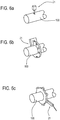
- the position sensor 21 is positioned close to the shaft 100 and it is, for example, an inductive proximity switch ( Figure 6c ).
- the position sensor 21 could be defined by:
- the first control unit 6 is programmed for setting the first amplifier module 7 in a high impedance configuration, that is to say, in the third state, during the second interval of time ⁇ T2, in such a way as to simulate a complete disconnection of the first amplifier module 7 from the circuit, allowing transmission of the measurement signal S4 from the second coil 5 to the first coil 4.
- the monitoring means 14 of the measuring unit 2 send to the second processing unit 8 the signal S3 representing an interruption in the transmission of energy.
- the second processing unit 8 sends to the second coil 5 a measurement signal S4 correlated with the signal S2 representing the forces measured by the sensor 9, which is transmitted by electromagnetic induction to the first coil 4.
- the storage module 13 of the measuring unit 2 is designed for storing energy when the generating module 6a generates the control signal S1 (in the first time interval ⁇ T1) and is designed for supplying at least part of the stored energy to the second processing unit 8 during the second time interval ( ⁇ T2 (that is, when the generation of the control signal S1 is interrupted).
- the second processing unit 8 is programmed for storing the data relative to the force status of the shaft 100, received through the signal S2 representing the forces measured by the sensor 9, during the first time intervals ⁇ T1, wherein the generating module 6a generates a control signal S1.
- the measurement signal S4 corresponds to the sequence of the signals S2 representing the forces measured sent by the sensor 9 to the second processing unit 8 during a first time interval ⁇ T1.
- the second processing unit 8 is programmed to act as a memory during feeding from the first coil 4 to the second coil 5 (that is, during the first time interval ⁇ T1) and to act as a data transmission module in the absence of that feeding (that is, during the second time interval ⁇ T2).
- the (second end 4b of the) first coil 4 is connected to the first processing unit 6, preferably using a data reception module 15, to send to the first processing unit 6, the measurement signal S4 (correlated with the forces measured).
- the first processing unit 6 is thus configured to receive and process the measurement signal S4 and, preferably, send it to a control system (not illustrated) of the plant in which the shaft 100 is mounted.
- both the first 6 and the second 8 processing units comprise a microprocessor.
- the microprocessor must have an extremely low current absorption (the microprocessor used to not be considered as a restriction is an 8 bit RISC microprocessor with 8 MHz clock frequencies.
- the microprocessor can be of any type as there are no particular constraints, either in terms of feed or speed.
- the measuring unit 2 also comprises an amplifier module 17 associated with the second processing unit 8, in particular operatively interposed between the second processing unit 8 and the first end 5a of the second coil 5.
- the above-mentioned amplifier module 17 is configured for increasing the power of the measurement signal S4 up to a predetermined transmission value, so as to allow the inductive transfer of the signal S4 to the first coil 4 by the second coil 5.
- the amplifier module 17 of the measuring unit 2 is defined by a driver configured to amplify the voltage and the current supplied by the second processing unit 8 to respective values designed to control the coils 4, 5.
- the storage module 13 is also connected to the amplifier module 17 of the measuring unit 2 in order to keep it fed during the interruption of the energy transmission from the first coil 4 to the second coil 5 (that is to say, when the generating module 6a generates a control signal S1 equal to the second value).
- the storage module 13 comprises two separate devices 13a, each connected, respectively, to the second control unit 8 or to the amplifier module 17; the purpose of this is to allow the second control unit 8 to remain fed during suspension of the transfer of energy from the first coil 4 to the second coil 5 and at the same time provide a separate source of energy sufficient to support the transmission of the measurement signal S4 from the second coil 5 to the first coil 4.
- the storage module 13 comprises a first device defined by the capacitor 13a described above and a second device comprising one or more block diodes 13b connected to the amplifier module 17.
- the block diodes 13b are low drop diodes (surface mounted) of theSchottky barrier small signal diode type.
- the apparatus 1 comprises a module 16 for interfacing with the control system associated with the first processing unit 6 and configured to make the data measured (relative to the forces on the 100) available to the control system.
- the data transfer (corresponding/correlated with the measurement signal S4) may occur in an analogue fashion, in the 0-10 VDC range (preferably 0-5 VDC), or by using a current channel in one of the following ranges:
- the transfer may also be performed using a digital support (not illustrated), such as, for example, the RS-485, CanBus or similar standard.
- a digital support such as, for example, the RS-485, CanBus or similar standard.
- the feed unit (or fixed unit) 3 and the measuring unit (or mobile unit) 2 are fully insulated from the galvanic point of view.
- the feed unit 3 and the measuring unit 2 are connectable to separate parts of the plant 101 and do not have in common any electrically conductive parts, either for signalling or feeding.
- the reference grounds GND1, GND2, that is, the negative pole of each supply are fully insulated (that is, independent) from each other.
- the measuring unit 2 has a relative first ground GND1 and the feed unit 3 has a respective second ground GND2.
- each unit (measuring 2 and feed 3) refers to the relative ground.
- this makes it possible to guarantee a greater immunity to electrical or magnetic disturbances.
- the measuring unit transfers the information to the feed unit 3 (in an electromagnetic form) using as reference potential that of the input, that is, that of feeding the feed unit 3.
- the signal when the level is distinct and well-defined and, more specifically, eliminating, possible errors when the signal.
- the invention achieves the proposed aims and brings significant advantages.
- the apparatus according to this invention wherein the feed and the data transmission follow the same path, in opposite directions, and occur by electromagnetic induction allows a dynamic measurement system to be obtained which is extremely precise, as well as easy and inexpensive to make.
- the measurement apparatus can be likened to an air-insulated transformer, that is, free of a core or laminated block since the majority of the flow lines pass mainly through the air and only a small part pass through the steel of the shaft.
Landscapes
- Engineering & Computer Science (AREA)
- Computer Networks & Wireless Communication (AREA)
- Physics & Mathematics (AREA)
- General Physics & Mathematics (AREA)
- Arrangements For Transmission Of Measured Signals (AREA)
- Investigating Strength Of Materials By Application Of Mechanical Stress (AREA)
- Facsimile Image Signal Circuits (AREA)
- Spinning Or Twisting Of Yarns (AREA)
Claims (14)
- Vorrichtung zur dynamischen Messung der Kraft auf einen Körper (100), der einer Verdrehung relativ zu einem Rahmen (101) unterzogen ist, umfassend:- eine Speiseeinheit (3), die mit dem Rahmen (101) assoziiert werden kann und ausgestattet ist mit:- einer ersten Spule (4), die koaxial zum Körper (100) angeordnet ist;- einer ersten Verarbeitungseinheit (6), die mit einem Erzeugungsmodul (6a) ausgestattet ist, das mit der ersten Spule (4) assoziiert und ausgelegt ist, um ein Steuersignal (S1) zu erzeugen und es an die erste Spule (4) zu senden, um ein elektromagnetisches Feld zu erzeugen;- einer Messeinheit (2), die zumindest teilweise am Körper (100) befestigt und ausgestattet werden kann mit:- einer zweiten Spule (5), die so auf den Körper (100) gewickelt ist, dass sie mit ihm beweglich ist und so positioniert ist, dass sie durch elektromagnetische Induktion von der ersten Spule (4) gespeist werden kann;- einer zweiten Verarbeitungseinheit (8), die mit der zweiten Spule (5) verbunden ist, um die in der zweiten Spule (5) induzierte Energie von der Speiseeinheit (3) zu empfangen;- einem Sensor (9) zum Messen der Kraft, der an dem Körper (100) befestigt werden kann, mit der zweiten Verarbeitungseinheit (8) verbunden und zum Senden eines Signals an die zweite Verarbeitungseinheit (8) ausgelegt, das den mindestens einen überwachten Parameter darstellt;wobei die Messeinheit (2) auch umfasst:- ein Modul (13) zum Speichern der mit der zweiten Spule (5) assoziierten Energie, das zum Empfangen der von der ersten Spule (4) induzierten und mit der zweiten Verarbeitungseinheit (8) verbundenen Energie ausgelegt ist;- Mittel (14), die mit der zweiten Verarbeitungseinheit (8) zur Überwachung der Energieübertragung von der ersten Spule (4) zur zweiten Spule (5) assoziiert und zum Senden eines Signals (S3) an die zweite Verarbeitungseinheit (8) konfiguriert sind, das eine Unterbrechung bei der Energieübertragung von der ersten Spule (4) zur zweiten Spule (5) darstellt, und dadurch, dass die zweite Verarbeitungseinheit (8) zum Senden eines Messsignals (S4) an die zweite Spule (5) ausgelegt ist, das mit dem Signal (S2) korreliert ist, das den mindestens einen überwachten Parameter, als Reaktion auf einen Empfang von den Überwachungsmitteln (14), des Signals (S3) darstellt, um das Messsignal (S4) an die Speiseeinheit (3) durch elektromagnetische Induktion von der zweiten Spule (5) zur ersten Spule (4) zu übertragen; dadurch gekennzeichnet, dass sie einen Positionssensor (21) umfasst, der mit der zu überwachenden Welle (100) assoziiert werden kann und die ausgelegt ist, um die Winkelposition der Welle (100) während ihrer Drehung zu messen, wobei der Positionssensor (12) betriebswirksam mit der ersten Verarbeitungseinheit (6) assoziiert und konfiguriert ist, um der ersten Verarbeitungseinheit (6) ein Signal (S5) zuzuführen, das die Winkelposition der Welle (100) darstellt; wobei die erste Verarbeitungseinheit (6) ist:- bereitgestellt, um vom Positionssensor (21) das Signal (S5) zu empfangen, das die Winkelposition der Welle (100) darstellt,- programmiert, um das Signal (S5) mit mindestens einem eingegebenen Winkelpositionswert zu vergleichen und- konfiguriert, um das Erzeugungsmodul (6a) in Abhängigkeit von diesem Vergleich zu steuern;
und dadurch, dass die Messeinheit (2) und die Speiseeinheit (3) jeweils eine erste Bezugsmasse (GND1) und eine zweite Bezugsmasse (GND) aufweisen, die vollständig voneinander isoliert sind, so dass die Speiseeinheit (3) und die Messeinheit (2) aus galvanischer Sicht vollständig isoliert sind. - Messvorrichtung nach Anspruch 1, dadurch gekennzeichnet, dass das Erzeugungsmodul (6a) der ersten Verarbeitungseinheit (6) ausgelegt ist, um ein Steuersignal (S1) mit variabler Intensität über die Zeit für ein vorbestimmtes erstes Zeitintervall (ΔT1) an die erste Spule (4) zu senden, mit dem die erste Spule (4) durch elektromagnetische Induktion Energie auf die zweite Spule (5) transferiert, und um die Erzeugung des Steuersignals (S1) für ein zweites Zeitintervall (ΔT2) nach dem ersten Zeitintervall (ΔT1) zu unterbrechen, um die Energieübertragung von der ersten Spule (4) zu unterbrechen.
- Messvorrichtung nach Anspruch 2, dadurch gekennzeichnet, dass das Steuersignal (S1) einen Rechteckwellentrend aufweist, der in einem Schritt zwischen einem ersten und einem zweiten Wert variabel ist.
- Messvorrichtung nach Anspruch 2 oder 3, dadurch gekennzeichnet, dass das Speichermodul (13) der Messeinheit (2) zum Speichern von Energie während jedes ersten Zeitintervalls (ΔT1) ausgelegt ist und zum Zuführen von mindestens einem Teil der gespeicherten Energie an die zweite Verarbeitungseinheit (8) während jedes zweiten Zeitintervalls (ΔT2) ausgelegt ist.
- Messvorrichtung nach Anspruch 1, dadurch gekennzeichnet, dass die Speiseeinheit (3) ein Schnittstellenmodul (16) umfasst, das mit der ersten Verarbeitungseinheit (6) verbunden und so ausgelegt ist, dass eine Einstellung des Wertes von mindestens einer vorbestimmten Referenzwinkelposition ermöglicht wird.
- Messvorrichtung nach einem der vorhergehenden Ansprüche, dadurch gekennzeichnet, dass die Speiseeinheit (3) ein Verstärkermodul (7) umfasst, das mit dem Erzeugungsmodul (6a) der ersten Verarbeitungseinheit (6) assoziiert ist und zum Erhöhen der Leistung des Steuersignals (S1) bis zu einem vorbestimmten Übertragungswert ausgelegt ist, um die induktive Speisung der zweiten Spule (5) durch die erste Spule (4) zu ermöglichen.
- Messvorrichtung nach einem der vorhergehenden Ansprüche, dadurch gekennzeichnet, dass die Messeinheit (2) ein Verstärkermodul (17) umfasst, das mit der zweiten Verarbeitungseinheit (8) assoziiert ist und zum Erhöhen der Leistung des Messsignals (S4) bis zu einem vorbestimmten Übertragungswert ausgelegt ist, um den induktiven Transfer des Signals zur ersten Spule (4) durch die zweite Spule (5) zu ermöglichen.
- Messvorrichtung nach einem der vorhergehenden Ansprüche, dadurch gekennzeichnet, dass der Sensor (9) einen Extensometer (10) umfasst, der starr mit dem Körper (100) verbindbar ist.
- Messvorrichtung nach Anspruch 8, dadurch gekennzeichnet, dass der Sensor (9) mindestens ein Paar Extensometer (10) umfasst, die jeweils einen Widerstand (11a) einer Wheatstone-Brücke (11) bilden; wobei der mindestens eine Parameter einer Verdrehkraft des Körpers (100) entspricht.
- Messvorrichtung nach einem der vorhergehenden Ansprüche, dadurch gekennzeichnet, dass die erste Spule (4) und die zweite Spule (5) jeweils auf einen jeweiligen Träger (18, 19) mit einer ringförmigen Form aus nicht ferromagnetischem Material gewickelt sind, um das von den Spulen (4, 5) erzeugte Magnetfeld nicht zu stören.
- Messvorrichtung nach einem der vorhergehenden Ansprüche, dadurch gekennzeichnet, dass die erste Spule (4) koaxial zu der zweiten Spule (5) ist und dieser zugewandt ist und in einem Abstand von 1 bis 50 mm von ihr positioniert ist.
- Messvorrichtung nach einem der vorhergehenden Ansprüche, dadurch gekennzeichnet, dass die Speiseeinheit (3) ein Schnittstellenmodul (16) umfasst, das mit der ersten Verarbeitungseinheit (6) verbunden ist und zur Kommunikation mit einem Steuersystem zum Senden an das Steuerungssystem das Messsignal (S4) und/oder ein Alarmsignal ausgelegt ist, wenn ein Schwellenwert der gemessenen Kräfte überschritten wird.
- Messvorrichtung nach einem der vorhergehenden Ansprüche, dadurch gekennzeichnet, dass die Speiseeinheit (3) ein Datenempfangsmodul (15) umfasst, das mit der ersten Spule (4) assoziiert ist, das zum Empfangen des Messsignals (S4) ausgelegt und konfiguriert ist, um es an die erste Verarbeitungseinheit (6) zu senden.
- Industrieanlage umfassend:- eine Basis;- einen festen Rahmen (101), der sich von der Basis erhebt;- mindestens eine Welle (100), die um eine relative Drehachse drehbar ist;- eine Vorrichtung (1) zur dynamischen Messung der mit der Welle (100) assoziierten Verdrehkräfte;- eine Benutzerschnittstelle, die mit mindestens einem Modul zum Anzeigen von Daten und mindestens einem Modul zum Eingeben von Parametern versehen ist, die beide mit der Messvorrichtung (1) assoziiert und so konfiguriert sind, dass sie einen wechselseitigen Datenaustausch ermöglichen;
dadurch gekennzeichnet, dass die dynamische Messvorrichtung (1) eine Messvorrichtung nach einem der vorhergehenden Ansprüche ist.
Applications Claiming Priority (2)
| Application Number | Priority Date | Filing Date | Title |
|---|---|---|---|
| IT000008A ITRN20130008A1 (it) | 2013-03-28 | 2013-03-28 | Apparecchiatura e metodo di misura dinamica di parametri su un corpo sottoposto a torsione. |
| PCT/IB2014/060216 WO2014155334A2 (en) | 2013-03-28 | 2014-03-27 | Apparatus and method for dynamic measurement of parameters on a body subjected to twisting |
Publications (2)
| Publication Number | Publication Date |
|---|---|
| EP2979069A2 EP2979069A2 (de) | 2016-02-03 |
| EP2979069B1 true EP2979069B1 (de) | 2020-04-22 |
Family
ID=48485356
Family Applications (1)
| Application Number | Title | Priority Date | Filing Date |
|---|---|---|---|
| EP14721508.1A Active EP2979069B1 (de) | 2013-03-28 | 2014-03-27 | Vorrichtung zur dynamischen messung von parametern eines verdrehten körpers |
Country Status (3)
| Country | Link |
|---|---|
| EP (1) | EP2979069B1 (de) |
| IT (1) | ITRN20130008A1 (de) |
| WO (1) | WO2014155334A2 (de) |
Families Citing this family (2)
| Publication number | Priority date | Publication date | Assignee | Title |
|---|---|---|---|---|
| RU2729412C1 (ru) * | 2017-06-08 | 2020-08-06 | Тирсан Кардан Санайи Ве Тикарет Аноним Сиркети | Механическое устройство, обеспечивающее непрерывную беспроводную передачу электрического питания на карданном валу |
| IT201900024721A1 (it) * | 2019-12-19 | 2021-06-19 | Atlas Copco Ind Technique Ab | Trasduttore di misurazione delle caratteristiche di uno strumento di serraggio |
Family Cites Families (4)
| Publication number | Priority date | Publication date | Assignee | Title |
|---|---|---|---|---|
| EP0712105A3 (de) * | 1994-11-14 | 1997-02-05 | Clyde L Ruthroff | Übertragungssystem von elektrischer Energie und Daten |
| DE59708895D1 (de) * | 1996-06-24 | 2003-01-16 | Siemens Ag | Anordnung zur berührungslosen induktiven übertragung elektrischer messgrössen und/oder elektrischer energie zwischen einem rotor und einem stator |
| US7256505B2 (en) | 2003-03-05 | 2007-08-14 | Microstrain, Inc. | Shaft mounted energy harvesting for wireless sensor operation and data transmission |
| ITMI20070669A1 (it) * | 2007-04-02 | 2008-10-03 | Campagnolo Srl | Componente di bicicletta strumentato ed unita' di rilevamento per strumentare tale componente |
-
2013
- 2013-03-28 IT IT000008A patent/ITRN20130008A1/it unknown
-
2014
- 2014-03-27 EP EP14721508.1A patent/EP2979069B1/de active Active
- 2014-03-27 WO PCT/IB2014/060216 patent/WO2014155334A2/en not_active Ceased
Non-Patent Citations (1)
| Title |
|---|
| None * |
Also Published As
| Publication number | Publication date |
|---|---|
| ITRN20130008A1 (it) | 2014-09-29 |
| WO2014155334A3 (en) | 2014-12-04 |
| EP2979069A2 (de) | 2016-02-03 |
| WO2014155334A2 (en) | 2014-10-02 |
Similar Documents
| Publication | Publication Date | Title |
|---|---|---|
| US7719264B2 (en) | Rotary transducer and method for operating a rotary transducer | |
| EP1870198B1 (de) | Steuersystem Auswuchten einer Werkzeugmaschine mit sich drehenden Werkzeugen | |
| JPH01307602A (ja) | 接触ヘッドの誘導信号伝送装置 | |
| CN106574829A (zh) | 旋转检测装置 | |
| KR20050086739A (ko) | 타이어 데이터 감지 시스템 | |
| US11196238B2 (en) | Device for detecting contact with an electrical conductor, method for identifying contact with an electrical conductor, insulation stripping machine comprising a device of this kind | |
| JP2003042151A (ja) | 転がり軸受装置及びこの軸受装置のセンサ付きリング | |
| AU2025200112A2 (en) | A multisensor contained in a seal of a conveyor belt roller | |
| EP2979069A2 (de) | Vorrichtung und verfahren zur dynamischen messung von parametern eines verdrehten körpers | |
| EP3552886A1 (de) | Drahtlose sensorschnittstelle für ein lenkrad | |
| KR100692129B1 (ko) | 토크 측정장치 | |
| CN106471342B (zh) | 传感器装置以及具有这种传感器装置的滚动轴承 | |
| CN102722214A (zh) | 一种旋钮 | |
| US10778033B2 (en) | Connection element, sensor, and sensor arrangement for process automation | |
| JP6045564B2 (ja) | 位置測定装置 | |
| US11499842B2 (en) | Position detection system and method for detecting a movement of a machine | |
| CN106662426A (zh) | 旋转检测器 | |
| EP3582201B1 (de) | Sender mit druckresistenter eingabe und intrinsisch sicherer ausgabe | |
| JP2021095960A (ja) | センサ付き軸受および計測システム | |
| JP6137627B2 (ja) | 計測システム、タッチプローブ、及び受信ユニット | |
| US10116110B2 (en) | Rotor arrangement for a slip ring assembly and rotary coupling arrangement comprising a rotor arrangement of this kind | |
| US20150241249A1 (en) | Sensor system for detecting position of target member | |
| US9964418B2 (en) | Inter-sensor communication system for absolute position sensing | |
| EP4076848B1 (de) | Wandler zum messen der eigenschaften eines spanninstruments | |
| KR102199971B1 (ko) | 토크 측정 장치 |
Legal Events
| Date | Code | Title | Description |
|---|---|---|---|
| PUAI | Public reference made under article 153(3) epc to a published international application that has entered the european phase |
Free format text: ORIGINAL CODE: 0009012 |
|
| 17P | Request for examination filed |
Effective date: 20150929 |
|
| AK | Designated contracting states |
Kind code of ref document: A2 Designated state(s): AL AT BE BG CH CY CZ DE DK EE ES FI FR GB GR HR HU IE IS IT LI LT LU LV MC MK MT NL NO PL PT RO RS SE SI SK SM TR |
|
| AX | Request for extension of the european patent |
Extension state: BA ME |
|
| DAX | Request for extension of the european patent (deleted) | ||
| RAP1 | Party data changed (applicant data changed or rights of an application transferred) |
Owner name: AUTEC S.R.L. |
|
| RIC1 | Information provided on ipc code assigned before grant |
Ipc: G08C 17/04 20060101ALI20191014BHEP Ipc: H04Q 9/00 20060101ALI20191014BHEP Ipc: G01L 3/10 20060101AFI20191014BHEP |
|
| GRAP | Despatch of communication of intention to grant a patent |
Free format text: ORIGINAL CODE: EPIDOSNIGR1 |
|
| STAA | Information on the status of an ep patent application or granted ep patent |
Free format text: STATUS: GRANT OF PATENT IS INTENDED |
|
| INTG | Intention to grant announced |
Effective date: 20200114 |
|
| GRAS | Grant fee paid |
Free format text: ORIGINAL CODE: EPIDOSNIGR3 |
|
| GRAA | (expected) grant |
Free format text: ORIGINAL CODE: 0009210 |
|
| STAA | Information on the status of an ep patent application or granted ep patent |
Free format text: STATUS: THE PATENT HAS BEEN GRANTED |
|
| AK | Designated contracting states |
Kind code of ref document: B1 Designated state(s): AL AT BE BG CH CY CZ DE DK EE ES FI FR GB GR HR HU IE IS IT LI LT LU LV MC MK MT NL NO PL PT RO RS SE SI SK SM TR |
|
| REG | Reference to a national code |
Ref country code: CH Ref legal event code: EP |
|
| REG | Reference to a national code |
Ref country code: IE Ref legal event code: FG4D |
|
| REG | Reference to a national code |
Ref country code: DE Ref legal event code: R096 Ref document number: 602014064091 Country of ref document: DE |
|
| REG | Reference to a national code |
Ref country code: AT Ref legal event code: REF Ref document number: 1260748 Country of ref document: AT Kind code of ref document: T Effective date: 20200515 |
|
| REG | Reference to a national code |
Ref country code: LT Ref legal event code: MG4D |
|
| REG | Reference to a national code |
Ref country code: NL Ref legal event code: MP Effective date: 20200422 |
|
| PG25 | Lapsed in a contracting state [announced via postgrant information from national office to epo] |
Ref country code: SE Free format text: LAPSE BECAUSE OF FAILURE TO SUBMIT A TRANSLATION OF THE DESCRIPTION OR TO PAY THE FEE WITHIN THE PRESCRIBED TIME-LIMIT Effective date: 20200422 Ref country code: NL Free format text: LAPSE BECAUSE OF FAILURE TO SUBMIT A TRANSLATION OF THE DESCRIPTION OR TO PAY THE FEE WITHIN THE PRESCRIBED TIME-LIMIT Effective date: 20200422 Ref country code: LT Free format text: LAPSE BECAUSE OF FAILURE TO SUBMIT A TRANSLATION OF THE DESCRIPTION OR TO PAY THE FEE WITHIN THE PRESCRIBED TIME-LIMIT Effective date: 20200422 Ref country code: GR Free format text: LAPSE BECAUSE OF FAILURE TO SUBMIT A TRANSLATION OF THE DESCRIPTION OR TO PAY THE FEE WITHIN THE PRESCRIBED TIME-LIMIT Effective date: 20200723 Ref country code: FI Free format text: LAPSE BECAUSE OF FAILURE TO SUBMIT A TRANSLATION OF THE DESCRIPTION OR TO PAY THE FEE WITHIN THE PRESCRIBED TIME-LIMIT Effective date: 20200422 Ref country code: NO Free format text: LAPSE BECAUSE OF FAILURE TO SUBMIT A TRANSLATION OF THE DESCRIPTION OR TO PAY THE FEE WITHIN THE PRESCRIBED TIME-LIMIT Effective date: 20200722 Ref country code: PT Free format text: LAPSE BECAUSE OF FAILURE TO SUBMIT A TRANSLATION OF THE DESCRIPTION OR TO PAY THE FEE WITHIN THE PRESCRIBED TIME-LIMIT Effective date: 20200824 Ref country code: IS Free format text: LAPSE BECAUSE OF FAILURE TO SUBMIT A TRANSLATION OF THE DESCRIPTION OR TO PAY THE FEE WITHIN THE PRESCRIBED TIME-LIMIT Effective date: 20200822 |
|
| REG | Reference to a national code |
Ref country code: AT Ref legal event code: MK05 Ref document number: 1260748 Country of ref document: AT Kind code of ref document: T Effective date: 20200422 |
|
| PG25 | Lapsed in a contracting state [announced via postgrant information from national office to epo] |
Ref country code: LV Free format text: LAPSE BECAUSE OF FAILURE TO SUBMIT A TRANSLATION OF THE DESCRIPTION OR TO PAY THE FEE WITHIN THE PRESCRIBED TIME-LIMIT Effective date: 20200422 Ref country code: HR Free format text: LAPSE BECAUSE OF FAILURE TO SUBMIT A TRANSLATION OF THE DESCRIPTION OR TO PAY THE FEE WITHIN THE PRESCRIBED TIME-LIMIT Effective date: 20200422 Ref country code: RS Free format text: LAPSE BECAUSE OF FAILURE TO SUBMIT A TRANSLATION OF THE DESCRIPTION OR TO PAY THE FEE WITHIN THE PRESCRIBED TIME-LIMIT Effective date: 20200422 Ref country code: BG Free format text: LAPSE BECAUSE OF FAILURE TO SUBMIT A TRANSLATION OF THE DESCRIPTION OR TO PAY THE FEE WITHIN THE PRESCRIBED TIME-LIMIT Effective date: 20200722 |
|
| PG25 | Lapsed in a contracting state [announced via postgrant information from national office to epo] |
Ref country code: AL Free format text: LAPSE BECAUSE OF FAILURE TO SUBMIT A TRANSLATION OF THE DESCRIPTION OR TO PAY THE FEE WITHIN THE PRESCRIBED TIME-LIMIT Effective date: 20200422 |
|
| REG | Reference to a national code |
Ref country code: DE Ref legal event code: R097 Ref document number: 602014064091 Country of ref document: DE |
|
| PG25 | Lapsed in a contracting state [announced via postgrant information from national office to epo] |
Ref country code: RO Free format text: LAPSE BECAUSE OF FAILURE TO SUBMIT A TRANSLATION OF THE DESCRIPTION OR TO PAY THE FEE WITHIN THE PRESCRIBED TIME-LIMIT Effective date: 20200422 Ref country code: CZ Free format text: LAPSE BECAUSE OF FAILURE TO SUBMIT A TRANSLATION OF THE DESCRIPTION OR TO PAY THE FEE WITHIN THE PRESCRIBED TIME-LIMIT Effective date: 20200422 Ref country code: ES Free format text: LAPSE BECAUSE OF FAILURE TO SUBMIT A TRANSLATION OF THE DESCRIPTION OR TO PAY THE FEE WITHIN THE PRESCRIBED TIME-LIMIT Effective date: 20200422 Ref country code: DK Free format text: LAPSE BECAUSE OF FAILURE TO SUBMIT A TRANSLATION OF THE DESCRIPTION OR TO PAY THE FEE WITHIN THE PRESCRIBED TIME-LIMIT Effective date: 20200422 Ref country code: SM Free format text: LAPSE BECAUSE OF FAILURE TO SUBMIT A TRANSLATION OF THE DESCRIPTION OR TO PAY THE FEE WITHIN THE PRESCRIBED TIME-LIMIT Effective date: 20200422 Ref country code: IT Free format text: LAPSE BECAUSE OF FAILURE TO SUBMIT A TRANSLATION OF THE DESCRIPTION OR TO PAY THE FEE WITHIN THE PRESCRIBED TIME-LIMIT Effective date: 20200422 Ref country code: AT Free format text: LAPSE BECAUSE OF FAILURE TO SUBMIT A TRANSLATION OF THE DESCRIPTION OR TO PAY THE FEE WITHIN THE PRESCRIBED TIME-LIMIT Effective date: 20200422 Ref country code: EE Free format text: LAPSE BECAUSE OF FAILURE TO SUBMIT A TRANSLATION OF THE DESCRIPTION OR TO PAY THE FEE WITHIN THE PRESCRIBED TIME-LIMIT Effective date: 20200422 |
|
| PG25 | Lapsed in a contracting state [announced via postgrant information from national office to epo] |
Ref country code: PL Free format text: LAPSE BECAUSE OF FAILURE TO SUBMIT A TRANSLATION OF THE DESCRIPTION OR TO PAY THE FEE WITHIN THE PRESCRIBED TIME-LIMIT Effective date: 20200422 Ref country code: SK Free format text: LAPSE BECAUSE OF FAILURE TO SUBMIT A TRANSLATION OF THE DESCRIPTION OR TO PAY THE FEE WITHIN THE PRESCRIBED TIME-LIMIT Effective date: 20200422 |
|
| PLBE | No opposition filed within time limit |
Free format text: ORIGINAL CODE: 0009261 |
|
| STAA | Information on the status of an ep patent application or granted ep patent |
Free format text: STATUS: NO OPPOSITION FILED WITHIN TIME LIMIT |
|
| 26N | No opposition filed |
Effective date: 20210125 |
|
| PG25 | Lapsed in a contracting state [announced via postgrant information from national office to epo] |
Ref country code: SI Free format text: LAPSE BECAUSE OF FAILURE TO SUBMIT A TRANSLATION OF THE DESCRIPTION OR TO PAY THE FEE WITHIN THE PRESCRIBED TIME-LIMIT Effective date: 20200422 |
|
| PG25 | Lapsed in a contracting state [announced via postgrant information from national office to epo] |
Ref country code: MC Free format text: LAPSE BECAUSE OF FAILURE TO SUBMIT A TRANSLATION OF THE DESCRIPTION OR TO PAY THE FEE WITHIN THE PRESCRIBED TIME-LIMIT Effective date: 20200422 |
|
| REG | Reference to a national code |
Ref country code: CH Ref legal event code: PL |
|
| REG | Reference to a national code |
Ref country code: BE Ref legal event code: MM Effective date: 20210331 |
|
| PG25 | Lapsed in a contracting state [announced via postgrant information from national office to epo] |
Ref country code: CH Free format text: LAPSE BECAUSE OF NON-PAYMENT OF DUE FEES Effective date: 20210331 Ref country code: LU Free format text: LAPSE BECAUSE OF NON-PAYMENT OF DUE FEES Effective date: 20210327 Ref country code: LI Free format text: LAPSE BECAUSE OF NON-PAYMENT OF DUE FEES Effective date: 20210331 Ref country code: IE Free format text: LAPSE BECAUSE OF NON-PAYMENT OF DUE FEES Effective date: 20210327 |
|
| PG25 | Lapsed in a contracting state [announced via postgrant information from national office to epo] |
Ref country code: BE Free format text: LAPSE BECAUSE OF NON-PAYMENT OF DUE FEES Effective date: 20210331 |
|
| PG25 | Lapsed in a contracting state [announced via postgrant information from national office to epo] |
Ref country code: HU Free format text: LAPSE BECAUSE OF FAILURE TO SUBMIT A TRANSLATION OF THE DESCRIPTION OR TO PAY THE FEE WITHIN THE PRESCRIBED TIME-LIMIT; INVALID AB INITIO Effective date: 20140327 |
|
| PG25 | Lapsed in a contracting state [announced via postgrant information from national office to epo] |
Ref country code: CY Free format text: LAPSE BECAUSE OF FAILURE TO SUBMIT A TRANSLATION OF THE DESCRIPTION OR TO PAY THE FEE WITHIN THE PRESCRIBED TIME-LIMIT Effective date: 20200422 |
|
| PG25 | Lapsed in a contracting state [announced via postgrant information from national office to epo] |
Ref country code: MK Free format text: LAPSE BECAUSE OF FAILURE TO SUBMIT A TRANSLATION OF THE DESCRIPTION OR TO PAY THE FEE WITHIN THE PRESCRIBED TIME-LIMIT Effective date: 20200422 |
|
| PG25 | Lapsed in a contracting state [announced via postgrant information from national office to epo] |
Ref country code: TR Free format text: LAPSE BECAUSE OF FAILURE TO SUBMIT A TRANSLATION OF THE DESCRIPTION OR TO PAY THE FEE WITHIN THE PRESCRIBED TIME-LIMIT Effective date: 20200422 |
|
| PG25 | Lapsed in a contracting state [announced via postgrant information from national office to epo] |
Ref country code: MT Free format text: LAPSE BECAUSE OF FAILURE TO SUBMIT A TRANSLATION OF THE DESCRIPTION OR TO PAY THE FEE WITHIN THE PRESCRIBED TIME-LIMIT Effective date: 20200422 |
|
| PGFP | Annual fee paid to national office [announced via postgrant information from national office to epo] |
Ref country code: GB Payment date: 20260319 Year of fee payment: 13 |
|
| PGFP | Annual fee paid to national office [announced via postgrant information from national office to epo] |
Ref country code: DE Payment date: 20260320 Year of fee payment: 13 |
|
| PGFP | Annual fee paid to national office [announced via postgrant information from national office to epo] |
Ref country code: FR Payment date: 20260323 Year of fee payment: 13 |