EP2979170B1 - Herstellung von rechenspeicher- und expansionsbladevorrichtungen zur verwendung für ein betriebssystem - Google Patents
Herstellung von rechenspeicher- und expansionsbladevorrichtungen zur verwendung für ein betriebssystem Download PDFInfo
- Publication number
- EP2979170B1 EP2979170B1 EP13880256.6A EP13880256A EP2979170B1 EP 2979170 B1 EP2979170 B1 EP 2979170B1 EP 13880256 A EP13880256 A EP 13880256A EP 2979170 B1 EP2979170 B1 EP 2979170B1
- Authority
- EP
- European Patent Office
- Prior art keywords
- expansion
- logical processor
- compute
- blade device
- memory
- Prior art date
- Legal status (The legal status is an assumption and is not a legal conclusion. Google has not performed a legal analysis and makes no representation as to the accuracy of the status listed.)
- Active
Links
Images


Classifications
-
- H—ELECTRICITY
- H04—ELECTRIC COMMUNICATION TECHNIQUE
- H04L—TRANSMISSION OF DIGITAL INFORMATION, e.g. TELEGRAPHIC COMMUNICATION
- H04L41/00—Arrangements for maintenance, administration or management of data switching networks, e.g. of packet switching networks
- H04L41/50—Network service management, e.g. ensuring proper service fulfilment according to agreements
- H04L41/5041—Network service management, e.g. ensuring proper service fulfilment according to agreements characterised by the time relationship between creation and deployment of a service
- H04L41/5054—Automatic deployment of services triggered by the service manager, e.g. service implementation by automatic configuration of network components
-
- G—PHYSICS
- G06—COMPUTING OR CALCULATING; COUNTING
- G06F—ELECTRIC DIGITAL DATA PROCESSING
- G06F9/00—Arrangements for program control, e.g. control units
- G06F9/06—Arrangements for program control, e.g. control units using stored programs, i.e. using an internal store of processing equipment to receive or retain programs
- G06F9/46—Multiprogramming arrangements
- G06F9/50—Allocation of resources, e.g. of the central processing unit [CPU]
- G06F9/5061—Partitioning or combining of resources
- G06F9/5077—Logical partitioning of resources; Management or configuration of virtualized resources
-
- G—PHYSICS
- G06—COMPUTING OR CALCULATING; COUNTING
- G06F—ELECTRIC DIGITAL DATA PROCESSING
- G06F11/00—Error detection; Error correction; Monitoring
- G06F11/07—Responding to the occurrence of a fault, e.g. fault tolerance
- G06F11/0703—Error or fault processing not based on redundancy, i.e. by taking additional measures to deal with the error or fault not making use of redundancy in operation, in hardware, or in data representation
- G06F11/0706—Error or fault processing not based on redundancy, i.e. by taking additional measures to deal with the error or fault not making use of redundancy in operation, in hardware, or in data representation the processing taking place on a specific hardware platform or in a specific software environment
- G06F11/0709—Error or fault processing not based on redundancy, i.e. by taking additional measures to deal with the error or fault not making use of redundancy in operation, in hardware, or in data representation the processing taking place on a specific hardware platform or in a specific software environment in a distributed system consisting of a plurality of standalone computer nodes, e.g. clusters, client-server systems
-
- G—PHYSICS
- G06—COMPUTING OR CALCULATING; COUNTING
- G06F—ELECTRIC DIGITAL DATA PROCESSING
- G06F11/00—Error detection; Error correction; Monitoring
- G06F11/07—Responding to the occurrence of a fault, e.g. fault tolerance
- G06F11/0703—Error or fault processing not based on redundancy, i.e. by taking additional measures to deal with the error or fault not making use of redundancy in operation, in hardware, or in data representation
- G06F11/0751—Error or fault detection not based on redundancy
-
- G—PHYSICS
- G06—COMPUTING OR CALCULATING; COUNTING
- G06F—ELECTRIC DIGITAL DATA PROCESSING
- G06F11/00—Error detection; Error correction; Monitoring
- G06F11/07—Responding to the occurrence of a fault, e.g. fault tolerance
- G06F11/0703—Error or fault processing not based on redundancy, i.e. by taking additional measures to deal with the error or fault not making use of redundancy in operation, in hardware, or in data representation
- G06F11/0766—Error or fault reporting or storing
- G06F11/0772—Means for error signaling, e.g. using interrupts, exception flags, dedicated error registers
-
- G—PHYSICS
- G06—COMPUTING OR CALCULATING; COUNTING
- G06F—ELECTRIC DIGITAL DATA PROCESSING
- G06F3/00—Input arrangements for transferring data to be processed into a form capable of being handled by the computer; Output arrangements for transferring data from processing unit to output unit, e.g. interface arrangements
- G06F3/06—Digital input from, or digital output to, record carriers, e.g. RAID, emulated record carriers or networked record carriers
-
- G—PHYSICS
- G06—COMPUTING OR CALCULATING; COUNTING
- G06F—ELECTRIC DIGITAL DATA PROCESSING
- G06F9/00—Arrangements for program control, e.g. control units
- G06F9/06—Arrangements for program control, e.g. control units using stored programs, i.e. using an internal store of processing equipment to receive or retain programs
- G06F9/44—Arrangements for executing specific programs
- G06F9/455—Emulation; Interpretation; Software simulation, e.g. virtualisation or emulation of application or operating system execution engines
-
- G—PHYSICS
- G06—COMPUTING OR CALCULATING; COUNTING
- G06F—ELECTRIC DIGITAL DATA PROCESSING
- G06F9/00—Arrangements for program control, e.g. control units
- G06F9/06—Arrangements for program control, e.g. control units using stored programs, i.e. using an internal store of processing equipment to receive or retain programs
- G06F9/44—Arrangements for executing specific programs
- G06F9/455—Emulation; Interpretation; Software simulation, e.g. virtualisation or emulation of application or operating system execution engines
- G06F9/45533—Hypervisors; Virtual machine monitors
-
- G—PHYSICS
- G06—COMPUTING OR CALCULATING; COUNTING
- G06F—ELECTRIC DIGITAL DATA PROCESSING
- G06F9/00—Arrangements for program control, e.g. control units
- G06F9/06—Arrangements for program control, e.g. control units using stored programs, i.e. using an internal store of processing equipment to receive or retain programs
- G06F9/44—Arrangements for executing specific programs
- G06F9/455—Emulation; Interpretation; Software simulation, e.g. virtualisation or emulation of application or operating system execution engines
- G06F9/45533—Hypervisors; Virtual machine monitors
- G06F9/45558—Hypervisor-specific management and integration aspects
-
- G—PHYSICS
- G06—COMPUTING OR CALCULATING; COUNTING
- G06F—ELECTRIC DIGITAL DATA PROCESSING
- G06F9/00—Arrangements for program control, e.g. control units
- G06F9/06—Arrangements for program control, e.g. control units using stored programs, i.e. using an internal store of processing equipment to receive or retain programs
- G06F9/46—Multiprogramming arrangements
- G06F9/50—Allocation of resources, e.g. of the central processing unit [CPU]
-
- G—PHYSICS
- G06—COMPUTING OR CALCULATING; COUNTING
- G06F—ELECTRIC DIGITAL DATA PROCESSING
- G06F9/00—Arrangements for program control, e.g. control units
- G06F9/06—Arrangements for program control, e.g. control units using stored programs, i.e. using an internal store of processing equipment to receive or retain programs
- G06F9/46—Multiprogramming arrangements
- G06F9/50—Allocation of resources, e.g. of the central processing unit [CPU]
- G06F9/5005—Allocation of resources, e.g. of the central processing unit [CPU] to service a request
-
- G—PHYSICS
- G06—COMPUTING OR CALCULATING; COUNTING
- G06F—ELECTRIC DIGITAL DATA PROCESSING
- G06F9/00—Arrangements for program control, e.g. control units
- G06F9/06—Arrangements for program control, e.g. control units using stored programs, i.e. using an internal store of processing equipment to receive or retain programs
- G06F9/46—Multiprogramming arrangements
- G06F9/50—Allocation of resources, e.g. of the central processing unit [CPU]
- G06F9/5005—Allocation of resources, e.g. of the central processing unit [CPU] to service a request
- G06F9/5011—Allocation of resources, e.g. of the central processing unit [CPU] to service a request the resources being hardware resources other than CPUs, Servers and Terminals
-
- G—PHYSICS
- G06—COMPUTING OR CALCULATING; COUNTING
- G06F—ELECTRIC DIGITAL DATA PROCESSING
- G06F9/00—Arrangements for program control, e.g. control units
- G06F9/06—Arrangements for program control, e.g. control units using stored programs, i.e. using an internal store of processing equipment to receive or retain programs
- G06F9/46—Multiprogramming arrangements
- G06F9/50—Allocation of resources, e.g. of the central processing unit [CPU]
- G06F9/5005—Allocation of resources, e.g. of the central processing unit [CPU] to service a request
- G06F9/5011—Allocation of resources, e.g. of the central processing unit [CPU] to service a request the resources being hardware resources other than CPUs, Servers and Terminals
- G06F9/5016—Allocation of resources, e.g. of the central processing unit [CPU] to service a request the resources being hardware resources other than CPUs, Servers and Terminals the resource being the memory
-
- G—PHYSICS
- G06—COMPUTING OR CALCULATING; COUNTING
- G06F—ELECTRIC DIGITAL DATA PROCESSING
- G06F9/00—Arrangements for program control, e.g. control units
- G06F9/06—Arrangements for program control, e.g. control units using stored programs, i.e. using an internal store of processing equipment to receive or retain programs
- G06F9/46—Multiprogramming arrangements
- G06F9/50—Allocation of resources, e.g. of the central processing unit [CPU]
- G06F9/5005—Allocation of resources, e.g. of the central processing unit [CPU] to service a request
- G06F9/5011—Allocation of resources, e.g. of the central processing unit [CPU] to service a request the resources being hardware resources other than CPUs, Servers and Terminals
- G06F9/5022—Mechanisms to release resources
-
- G—PHYSICS
- G06—COMPUTING OR CALCULATING; COUNTING
- G06F—ELECTRIC DIGITAL DATA PROCESSING
- G06F9/00—Arrangements for program control, e.g. control units
- G06F9/06—Arrangements for program control, e.g. control units using stored programs, i.e. using an internal store of processing equipment to receive or retain programs
- G06F9/46—Multiprogramming arrangements
- G06F9/50—Allocation of resources, e.g. of the central processing unit [CPU]
- G06F9/5005—Allocation of resources, e.g. of the central processing unit [CPU] to service a request
- G06F9/5027—Allocation of resources, e.g. of the central processing unit [CPU] to service a request the resource being a machine, e.g. CPUs, Servers, Terminals
-
- G—PHYSICS
- G06—COMPUTING OR CALCULATING; COUNTING
- G06F—ELECTRIC DIGITAL DATA PROCESSING
- G06F9/00—Arrangements for program control, e.g. control units
- G06F9/06—Arrangements for program control, e.g. control units using stored programs, i.e. using an internal store of processing equipment to receive or retain programs
- G06F9/46—Multiprogramming arrangements
- G06F9/50—Allocation of resources, e.g. of the central processing unit [CPU]
- G06F9/5061—Partitioning or combining of resources
-
- G—PHYSICS
- G06—COMPUTING OR CALCULATING; COUNTING
- G06F—ELECTRIC DIGITAL DATA PROCESSING
- G06F9/00—Arrangements for program control, e.g. control units
- G06F9/06—Arrangements for program control, e.g. control units using stored programs, i.e. using an internal store of processing equipment to receive or retain programs
- G06F9/46—Multiprogramming arrangements
- G06F9/50—Allocation of resources, e.g. of the central processing unit [CPU]
- G06F9/5061—Partitioning or combining of resources
- G06F9/5066—Algorithms for mapping a plurality of inter-dependent sub-tasks onto a plurality of physical CPUs
-
- G—PHYSICS
- G06—COMPUTING OR CALCULATING; COUNTING
- G06F—ELECTRIC DIGITAL DATA PROCESSING
- G06F9/00—Arrangements for program control, e.g. control units
- G06F9/06—Arrangements for program control, e.g. control units using stored programs, i.e. using an internal store of processing equipment to receive or retain programs
- G06F9/46—Multiprogramming arrangements
- G06F9/50—Allocation of resources, e.g. of the central processing unit [CPU]
- G06F9/5061—Partitioning or combining of resources
- G06F9/5072—Grid computing
-
- H—ELECTRICITY
- H04—ELECTRIC COMMUNICATION TECHNIQUE
- H04L—TRANSMISSION OF DIGITAL INFORMATION, e.g. TELEGRAPHIC COMMUNICATION
- H04L67/00—Network arrangements or protocols for supporting network services or applications
- H04L67/50—Network services
- H04L67/51—Discovery or management thereof, e.g. service location protocol [SLP] or web services
-
- G—PHYSICS
- G06—COMPUTING OR CALCULATING; COUNTING
- G06F—ELECTRIC DIGITAL DATA PROCESSING
- G06F9/00—Arrangements for program control, e.g. control units
- G06F9/06—Arrangements for program control, e.g. control units using stored programs, i.e. using an internal store of processing equipment to receive or retain programs
- G06F9/44—Arrangements for executing specific programs
- G06F9/455—Emulation; Interpretation; Software simulation, e.g. virtualisation or emulation of application or operating system execution engines
- G06F9/45533—Hypervisors; Virtual machine monitors
- G06F9/45558—Hypervisor-specific management and integration aspects
- G06F2009/45579—I/O management, e.g. providing access to device drivers or storage
-
- G—PHYSICS
- G06—COMPUTING OR CALCULATING; COUNTING
- G06F—ELECTRIC DIGITAL DATA PROCESSING
- G06F9/00—Arrangements for program control, e.g. control units
- G06F9/06—Arrangements for program control, e.g. control units using stored programs, i.e. using an internal store of processing equipment to receive or retain programs
- G06F9/44—Arrangements for executing specific programs
- G06F9/455—Emulation; Interpretation; Software simulation, e.g. virtualisation or emulation of application or operating system execution engines
- G06F9/45533—Hypervisors; Virtual machine monitors
- G06F9/45558—Hypervisor-specific management and integration aspects
- G06F2009/45583—Memory management, e.g. access or allocation
Definitions
- a blade system may include a plurality of blade devices mounted in a blade enclosure.
- Each of the blade devices may be a blade server, for example.
- a user may set up a partition of the blade system to include one, several, or all of the blade devices mounted in the blade enclosure.
- the partition may run an operating system (OS) and run application(s) with the OS.
- OS operating system
- US 2006/0036889 A1 describes a method and system for enabling replacement of a failed processor without requiring redundancy of hardware.
- Each processor chip includes a plurality of logical processors.
- a table is generated to communicate a location of each logical and physical processor to an operating system. After the table has been generated, each processor in the system is designated as active and available to the operating system or as idle and unavailable to the operating system.
- EP 1636696 A2 describes a method of operating a blade server rack comprising a plurality of blade devices. Each blade device executes an operating system and is configured to share resources like hard drives or input devices with other blade devices in an operating system-independent manner.
- the blade devices are connected via a low-level communication channel that allows for the sharing of resources by requesting and providing access to resources through system management interrupts.
- US 2007/0150713 A1 discloses a method to dynamically adjust the number of available processors in a multi-node computing system. In response to an external command e.g. from a remote server, the number of processors of the computing system available to an operating system may be changed by selectively activating additional processors that are currently deactivated.
- the present invention provides a non-transitory machine-readable storage medium according to claim 1, a system according to claim 5, and a method according to claim 10. Examples of the invention are defined in the dependent claims.
- a partition of a blade system may run an operating system (OS) and run application(s) with the OS.
- the partition that runs the OS may include multiple blade devices, each including logical processor(s) and memory.
- Each logical processor may be included on an integrated circuit (IC) (e.g., a chip).
- An IC including at least one central processing unit (CPU) may be referred to herein as a "CPU IC".
- a CPU IC may include at least one integrated memory controller to manage memory of the blade device.
- a memory controller of a CPU IC may be able to manage a relatively limited amount of memory, which may limit the amount of memory available on a blade device, and thus in a partition.
- More memory may be added to a partition by adding additional blade device(s) to the partition.
- license costs for some applications run by the OS may be calculated based on the number logical processors available for the application to utilize.
- adding blade devices to a partition may substantially increase license costs for some applications due to the availability of the logical processors of the added blade devices.
- examples described herein may configure a compute logical processor of a compute blade device and an expansion logical processor of an expansion blade device to operate as part of a single SFW domain, and identify available memory of the compute blade device and available memory of the expansion blade device. Examples described herein may further make the compute logical processor and the identified memory of the compute and expansion blade devices available for use by an OS, and make the expansion logical processor unavailable to the OS while the expansion logical processor remains available to execute instructions of the SFW instance.
- examples described herein may enable a partition of a blade system to utilize memory of an expansion blade device without exposing logical processor(s) of the expansion blade device (i.e., expansion logical processor(s)) to the OS run by the partition or the applications run by the OS.
- examples described herein may enable a partition to use the memory of an expansion blade device for running an OS and application(s), without the expansion logical processor(s) of the expansion blade device increasing application license costs.
- an expansion logical processor made unavailable to the OS may remain available to collect error information at the expansion blade device, or otherwise manage resources of the expansion blade device under the control of instructions of the SFW instance, while still being unavailable for use by the OS.
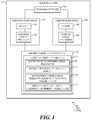
- FIG. 1 is a block diagram of an example blade system 100 to make a logical processor unavailable to an operating system (OS) while remaining available to execute instructions of a system firmware (SFW) instance.
- a blade system may be a computing system comprising a blade enclosure and at least one blade device mounted in the blade enclosure.
- blade system 100 comprises a blade enclosure 105, and expansion and compute blade devices 130 and 140 each mounted in blade enclosure 105.
- Blade system 100 may run an OS 115 with resources of each of expansion and compute blade devices 130 and 140.
- OS 115 may be run by a partition of blade system 100 including at least expansion and compute blade devices 130 and 140.
- a "blade device” may be a physical computing device that comprises memory and at least one logical processor, and that is mountable to a blade enclosure.
- a blade device may be a modular computing device that is physically mountable to a blade enclosure for operation, that includes certain core computing resources (e.g., logical processor(s) and memory), and that excludes certain peripheral computing resource(s) (e.g., a power supply, cooling fan(s), external networking ports, and the like, or a combination thereof).
- core computing resources e.g., logical processor(s) and memory
- peripheral computing resource(s) e.g., a power supply, cooling fan(s), external networking ports, and the like, or a combination thereof.
- a “blade enclosure” may be a chassis to receive a plurality of blade devices and provide at least one peripheral resource for the received blade devices.
- a blade enclosure may include fan(s) to cool mounted blade devices, at least one power supply to provide power to mounted blade devices, external network ports for mounted blade devices, and the like, or a combination thereof.
- expansion blade device 130 may include an expansion logical processor 132 and memory 134 associated with expansion logical processor 132.
- blade device 130 may include a plurality of logical processors, some or all of which having associated memory.
- Compute blade device 140 may include a compute logical processor 142 and memory 144 associated with compute logical processor 142.
- blade device 140 may include a plurality of logical processors, some or all of which having associated memory.
- a "logical processor" may be a CPU IC, a CPU of a CPU IC (e.g., one of a plurality of cores on a multi-core CPU IC), or a thread on a CPU (or core) of a CPU IC.
- any expansion blade device or compute blade device described herein may be a blade device as described above.
- an expansion blade device may be a blade device designated to provide memory, but not logical processor(s), for use by an OS of a partition including the blade device.
- a compute blade device may be a blade device designated to provide memory and logical processor(s) for use by an OS of a partition including the blade device.
- each blade device of a partition may be designated as an expansion or compute blade device in partition information describing aspects of the configuration of the partition.
- any expansion logical processor or compute logical processor described herein may be a logical processor as described above.
- an expansion logical processor may be a logical processor of an expansion blade device and a compute logical processor may be a logical processor of a compute blade device.
- a blade device including memory associated with a logical processor may comprise at least one memory module and a CPU IC including at least one logical processor (e.g., CPU or core) and at least one integrated memory controller to manage the memory module(s).
- a blade device may include a plurality of CPU ICs, each including at least one integrated memory controller to manage memory module(s) of the blade device.
- a memory module may be, for example, a dual in-line memory module (DIMM), a single in-line memory module (SIMM), or any other type of memory module including a plurality of memory devices.
- blade system 100 includes a machine-readable storage medium 120 encoded with a system firmware (SFW) instance 121 including instructions 122, 124, 126, and 128.
- SFW instance 121 may include additional instructions.
- a "machine-readable storage medium” may be any electronic, magnetic, optical, or other physical storage apparatus to contain or store information such as executable instructions, data, and the like.
- any machine-readable storage medium described herein may be any of random access memory (RAM), read-only memory (ROM), volatile memory, non-volatile memory, flash memory, a storage drive (e.g., a hard drive), a solid state drive, any type of storage disc (e.g., a Compact Disc Read Only Memory (CD-ROM), any other type of compact disc, a DVD, etc.), and the like, or a combination thereof.
- RAM random access memory
- ROM read-only memory
- volatile memory volatile memory
- non-volatile memory non-volatile memory
- flash memory e.g., a solid state drive
- any type of storage disc e.g., a Compact Disc Read Only Memory (CD-ROM), any other type of compact disc, a DVD, etc.
- CD-ROM Compact Disc Read Only Memory
- any other type of compact disc e.g., a DVD, etc.
- any machine-readable storage medium described herein may be non-transitory. Any "memory” described here
- storage medium 120 may be a ROM storing SFW instance 121.
- storage medium 120 may be included on expansion blade device 130 or compute blade device 140.
- storage medium 120 may be included on another blade device mounted to blade device enclosure 105.
- a "system firmware instance" (or "SFW instance”) may be a set of machine executable instructions to boot and manage resources of a blade device. For example, after a reset, a logical processor of a blade device may begin to execute instructions of a SFW instance to initialize the logical processor for operation, and to initialize other resource(s) of the blade device, such as the memory associated with the logical processor. In some examples, this initialization of the logical processor and the associated memory may include a power-on self-test (POST) implemented by the SFW instance.
- POST power-on self-test
- a SFW domain associated with the SFW instance
- a "system firmware domain" (or "SFW domain") associated with a SFW instance may be an environment in which a logical processor booted by the SFW instance may operate when executing instructions of the SFW instance after booting.
- a SFW domain may include a plurality of SFW resources, including, for example, SFW data structure(s) and SFW code (i.e., machine executable instructions).
- a logical processor operating as part of a SFW domain may be a logical processor having access to the SFW resources of the SFW domain.
- the SFW resources (e.g., the SFW data structure(s) and SFW code) of the SFW domain may be stored in a system management memory region (e.g., SMRAM) for the SFW domain.
- a logical processor operating as part of a SFW domain may be a logical processor having access to the SFW resources stored in the system management memory region for the SFW domain.
- a logical processor operating as part of a SFW domain may not have access to the SFW resources in the system management memory region at all times. Rather, the logical processor may have access at certain times (e.g., while booting), in certain mode(s) (e.g., a system management mode (SMM)), etc.
- SMM system management mode
- a logical processor having such limited access may still be considered to have access to the SFW resources in the system management memory region.
- the system management memory region may be at least a portion of a machine-readable storage medium of at least one blade device mounted in a blade enclosure including the logical processor.
- the SFW data structures may include, for example, advanced configuration and power interface (ACPI) table(s), system management BIOS (SMBIOS) table(s), memory data structures, interrupt vector(s), semaphores, and the like, or a combination thereof.
- the SFW data structure(s) may be generated and stored in the system management memory region by logical processor(s) executing instructions of the SFW instance.
- the SFW code may include executable instructions implementing interrupt service routines, such as system management interrupt (SMI) handler(s), or the like.
- SFW code may also include executable instructions implementing error handler(s).
- the SFW code may be instructions of the SFW instance copied into the system management memory region.
- instructions of SFW instance 121 are executable by blade system 100.
- expansion logical processor 132 and compute logical processor 142 of blade system 100 may fetch, decode, and execute instructions of SFW instance 121 to perform the functionalities described below in relation to SFW instance 121.
- instructions 122 when executed by logical processors 132 and 142 after a reset of at least a portion of blade system 100 (e.g., the partition to run OS 115), instructions 122 may configure compute logical processor 142 of compute blade device 140 and expansion logical processor 132 of expansion blade device 130 to operate as part of a single SFW domain associated with SFW instance 121.
- logical processors configured to operate as part of a single SFW domain may be logical processors that are each configured to access the SFW resources of the SFW domain.
- the logical processors may each have access (e.g., in SMM) to the system management memory region storing the SFW resources for the SFW domain.
- logical processors may be configured to operate as part of the same SFW domain by booting each of the logical processors with the same SFW instance 121.
- expansion and compute logical processors 132 and 142 may be configured to operate as part of a SFW domain associated with SFW instance 121 (i.e., the same SFW domain) by booting each of expansion and compute logical processors 132 and 142 with SFW instance 121.
- expansion and compute logical processors 132 and 142 may each boot by executing instructions of SFW instance 121, including instructions 122 to configure the logical processors to operate as part of the SFW domain associated with SFW instance 121.
- instructions 122 may configure the respective hardware address maps of expansion and compute logical processors 132 and 142 to be the same. For example, instructions 122 may configure the respective hardware address maps such that expansion and compute logical processors 132 and 142 each have access to the same SFW resources in the system management memory region. For example, instructions 122 may configure the hardware address maps such that logical processors 132 and 142 access the same SFW code (e.g., SMI handler(s), etc.) in the system management memory region.
- SFW code e.g., SMI handler(s), etc.
- Instructions 122 may also configure logical processors 132 and 142 to access the same state information for the SFW domain associated with SFW instance 121, including, for example, information regarding pending interrupts, loaded drivers, loaded ACPI tables, and the like, or a combination thereof.
- OS 115 may be run by a partition of blade system 100 including at least expansion and compute blade devices 130 and 140.
- the partition may run OS 115 with resources of each of expansion and compute blade devices 130 and 140.
- instructions 124 when executed by logical processors 132 and 142, instructions 124 may identify available memory of compute blade device 140 associated with compute logical processor 142 and identify available memory of expansion blade device 130 associated with expansion logical processor 132.
- the memory identified by instructions 124 may be memory determined to be available for use by an OS of blade system 100, such as OS 115.
- compute logical processor 142 may execute instructions 124 to identify available memory among memory 144 associated with compute logical processor 142. For example, compute logical processor 142 may execute instructions 124 as part of its boot process. In such examples, instructions 124 may determine the amount of memory 144 associated with logical processor 142 and then test memory 144 to determine what portion of memory 144 is useable (i.e., functional). In some examples, instructions 124 may identify at least a portion of the memory 144 determined to be useable as memory available for use by OS 115 (i.e., available memory).
- compute logical processor 142 may reserve a portion of useable memory 144 for use by the compute logical processor 142 (e.g., when executing instructions of SFW instance 121), and identify the remainder of useable memory 144 as available for use by OS 115.
- Compute logical processor 142 executing instructions 124 may also store a description of the identified available memory in a service memory of blade device 140.
- a service processor of blade device 140 when executing instructions of an instance of management firmware, may access the description and provide it to a monarch logical processor (e.g., a bootstrap logical processor) in charge of coordinating the booting of the partition to run OS 115.
- Expansion logical processor 132 may also execute instructions 124 to identify memory available for use by OS 115 (i.e., available memory) among memory 134 associated with expansion logical processor 132, as described above in relation to compute logical processor 142.
- Expansion logical processor 132 executing instructions 124 may also store a description of the identified available memory in a service memory of blade device 130 such that a service processor of blade device 130, when executing instructions of an instance of management firmware, may provide the description to the monarch logical processor.
- the descriptions of the identified available memory may be in any suitable data structure or format (e.g., a table, etc.).
- expansion logical processor 132 may access partition information describing at least some aspects of the configuration of the partition to which expansion blade device 130 belongs.
- the partition information may indicate whether blade device 130 is designated as an expansion or compute blade device for the partition.
- the partition information may include a flag indicating whether blade device 130 is designated as an expansion or compute blade device.
- the partition information may be stored in the system management memory region or in service memory of expansion blade device 130 as described above, for example.
- Expansion logical processor 132 may access the partition information after identifying available memory of memory 134, and before the control of the partition is handed over to OS 115, for example.
- expansion logical processor 132 may execute instructions 126 to make expansion logical processor 132 unavailable to OS 115 such that expansion logical processor 132 remains available to execute instructions of SFW instance 121.
- instructions 126 when executed by expansion logical processor 132, may cause expansion logical processor 132 to enter a system management mode (SMM) and remain in the SMM while OS 115 is executed by at least compute logical processor 142.
- SMM system management mode
- instructions 126 may place expansion logical processor 132 in SMM when executed by logical processor 132, and may cause expansion logical processor 132 to remain in SMM while the OS is executed by other logical processor(s) of the partition (i.e., compute logical processors of the partition).
- a system management mode may be a mode in which a logical processor executes SFW code of a SFW domain in which the logical processor is configured to operate.
- expansion logical processor 132 may have access to the system management memory region (e.g., SMRAM) of the SFW domain associated with SFW instance 121, and may execute SFW code (e.g., instructions of SFW instance 121) stored in the system management memory region.
- SMM expansion logical processor 132 is not available to be utilized by OS 115 to run any portion of OS 115 or any portion of an application run in OS 115, for example.
- expansion logical processor 132 remains available to execute instructions of SFW instance 121, such as instructions of an SMI handler in response to detection of an SMI and instructions of an error handler in response to an error indication, for example.
- the instructions of the SMI handler and the error handler may be instructions of SFW instance 121 and may have been copied into the system management memory region during the boot process.
- expansion logical processor 132 may execute these instructions out of the system management memory region.
- instructions 126 may make expansion logical processor 132 unavailable to OS 115 such that it remains available to execute instructions of SFW instance 121 in any other suitable manner.
- instructions 126 may cause expansion logical processor 132 to execute a loop implemented by instructions of SFW instance 121 such that expansion logical processor 132 remains executing instructions of SFW instance 121 and is available to be taken out of the loop to execute other SFW code, such as an SMI or error handler, as described above.
- instructions 128 may make available, for use by OS 115, compute logical processor 142, the identified memory of the compute blade device, and the identified memory of the expansion blade device.
- compute logical processor 142 may be the monarch logical processor for the partition.
- instructions 128 when executed by compute logical processor 142, instructions 128 may make the compute logical processor 142, the identified memory of the compute blade device, and the identified memory of the expansion blade device available for use by OS 115 by providing information identifying these resources to OS 115.
- the information identifying these resources may be provided to OS 115 in any suitable format or data structure (e.g., table(s), etc.).
- instructions 128 may provide this information to OS 115 in at least one ACPI table.
- instructions 128 may construct the ACPI table(s) based in part on the respective descriptions of the identified available memory of memory 134 and of the identified available memory of memory 144. In such examples, descriptions of memory associated with logical processors of other blade devices may also be provided to the monarch logical processor via service memory and service processor(s), as described above. Additionally, instructions 128 may exclude any identification of expansion logical processor 132 from the ACPI table(s), such that expansion logical processor 132 is not identified as available for OS 115 to utilize.
- OS 115 may run on the partition utilizing the resources identified to OS 115 by instructions 128. For example, OS 115 may execute and run application(s) using compute logical processor 142 and the identified available memory of memory 134 and 144 while expansion logical processor 132 is unavailable for use by OS 115 or any application(s) run by OS 115.
- functionalities described herein in relation to FIG. 1 may be provided in combination with functionalities described herein in relation to any of FIGS. 2-5 .
- FIG. 2 is a block diagram of an example blade system 200 to make a plurality of logical processors unavailable to an OS while remaining available to execute instructions of a SFW instance.
- blade system 200 comprises a blade enclosure 205, and blade devices 230 and 240 mounted in blade enclosure 205.
- Blade device 230 may be referred to herein as an expansion blade device 230
- blade device 240 may be referred to herein as a compute blade device 240.
- Blade system 200 may run an OS 115, as described above in relation to FIG. 1 , with resources of each of blade devices 230 and 240.
- OS 115 may be run by a partition of blade system 200 including at least blade devices 230 and 240.
- expansion blade device 230 may include an expansion logical processor 132 and memory 134 associated with expansion logical processor 132, as described above in relation to FIG. 1 .
- Expansion blade device 230 may also include an expansion logical processor 236 associated with memory 238 of blade device 230. In other examples, blade device 230 may include more than two logical processors, some or all of which having associated memory.
- Compute blade device 240 may include a compute logical processor 142 and memory 144 associated with compute logical processor 142, as described above in relation to FIG. 1 .
- Compute blade device 240 may also include a compute logical processor 246 associated with memory 248 of blade device 240. In other examples, blade device 240 may include more than two logical processors, some or all of which having associated memory.
- Blade system 200 also includes a machine-readable storage medium 120 encoded with SFW instance 121 including instructions 122, 124, 126, and 128, as described above in relation to FIG. 1 .
- SFW instance 121 may further include at least instructions 225.
- SFW instance 121 may include additional instructions. Instructions of SFW instance 121 are executable by blade system 200. Instructions of SFW instance 121 may be executable by logical processors 132, 236, 142, and 246 to perform the functionalities described below in relation to SFW instance 121.
- instructions 122 may configure each of compute logical processors 142 and 246 of compute blade device 240 and expansion logical processors 132 and 236 of expansion blade device 230 to operate as part of a single SFW domain associated with SFW instance 121, as described in relation to blade system 100 of FIG. 1 .
- each of logical processors 132, 236, 142, 246 may be configured to operate as part of a SFW domain associated with SFW instance 121 (i.e., as part of the same SFW domain) by booting each of logical processors 132, 236, 142, 246 with SFW instance 121.
- instructions 124 may, for each logical processor of the first and second pluralities of logical processors, identify available memory associated with the logical processor, as described above in relation to FIG. 1 .
- expansion logical processors 132 and 236 may identify available memory of memory 134 and 238, and compute logical processors 142 and 246 may identify available memory of memory 144 and 248.
- logical processors 132 and 236 may store description(s) 256 of the identified available memory in a service memory 235 of blade device 230.
- Description(s) 256 may be a single description of the memory identified by each of logical processors 132 and 236, or separate descriptions of the memory identified memory by each logical processor.
- a service processor of blade device 230 executing management firmware instructions may provide description(s) 256 to blade device 240, in examples in which blade device 240 includes the monarch logical processor (e.g., logical processor 142) for a partition of blade system 200 including blade devices 230 and 240.
- the service processor of blade device 230 may provide description(s) 256 to a service processor of blade device 240, which may store the received description(s) 256 in a service memory 245 of blade device 240 where description(s) 256 are accessible to the monarch logical processor (e.g., logical processor 142).
- logical processors on the same blade device as the monarch logical processor may communicate description(s) of identified memory to the monarch logical processor in any suitable manner.
- the logical processors of the first and second pluralities when executing instructions 124, may store descriptions of identified available memory in a shared memory region for the partition.
- the shared memory region may be implemented by memory of one blade device or memory regions of each of a plurality of blade devices of the partition.
- a service processor may be at least one of a CPU, a semiconductor-based microprocessor, other electronic circuitry suitable for the retrieval and execution instructions stored on a machine-readable storage medium, or a combination thereof
- OS 115 may be run by a partition of blade system 200 including at least blade devices 230 and 240.
- the partition may run OS 115 with resources of each of blade devices 230 and 240.
- blade system 200 may store partition information describing aspects of the configuration of the partition.
- instructions 225 may access partition information 237 designating blade device 230 as an expansion blade device.
- blade device 230 may comprise a first plurality of logical processors of blade system 200 including, for example, logical processors 132 and 236. Instructions 225 may also access partition information 247 designating blade device 240 as a compute blade device.
- blade device 240 may comprise a second plurality of logical processors of blade system 200 including, for example, logical processors 142 and 246.
- partition information 237 may be a portion of the partition information for the partition, and may include configuration information relevant to blade device 230.
- Blade device 230 may access the partition information for the partition with a service processor of blade device 230 and store partition information 237 in service memory 235 of blade device 230.
- partition information 247 may be a portion of the partition information for the partition, and may include configuration information relevant to blade device 240.
- Compute blade device 240 may access the partition information for the partition with a service processor of blade device 240 and store partition information 247 in service memory 245 of blade device 240.
- each of expansion logical processors 132 and 236, executing instructions 225 may access partition information 237 and determine, based on partition information 237, that blade device 230 is designated as an expansion blade device (i.e., designated as a blade device to provide memory for use by the OS and to provide no logical processors for use by the OS). Additionally, each of compute logical processors 142 and 246, executing instructions 225, may access partition information 247 and determine, based on partition information 247, that blade device 240 is designated as a compute blade device (i.e., designated as a blade device to provide memory and at least one logical processor for use by the OS).
- instructions 126 may make each of the first plurality of logical processors unavailable to the OS such that they each remain available to execute instructions of the SFW instance, as described above in relation to FIG. 1 .
- each of logical processors 132 and 236 may execute instructions 126 to enter and remain in SMM while OS 115 is executed by the partition.
- one of the logical processors of blade device 230 designated as an expansion blade device may be made unavailable to OS 115 such that it remains available to execute instructions of SFW instance 121, while the other logical processors of blade device 230 may be made unavailable to the OS such that they do not remain available to execute instructions of SFW instance 121.
- the rest of the logical processors of blade device 230 may be placed in a halt state, an initialization state (e.g., waiting for startup inter-processor interrupt (SIPI)), or the like.
- the one logical processor remaining available to execute instructions of SFW instance 121 may be used for management of the blade device.
- one logical processor of each expansion blade device may remain available to execute instructions of SFW instance 121, for example.
- instructions 128 may make available, for use by OS 115, each of the second plurality of logical processors, the identified memory associated with each logical processor of the first plurality, and the identified memory associated with each logical processor of the second plurality of logical processors. Instructions 128 may make these resources available for use by OS 115 as described above in relation to FIG. 1 . For example, instructions 128 may generate at least one ACPI table 252 to be provided to OS 115.
- compute logical processor 142 may be the monarch logical processor for the partition to run OS 115.
- instructions 128 when executed by compute logical processor 142, instructions 128 may indicate, in at least one of ACPI table(s) 252, that compute logical processors 132 and 142 are available for use by OS 115. Instructions 128 may also indicate, at least one of ACPI table(s) 252, that the identified memory of compute blade device 240 and the identified memory of expansion blade device 230 are available for use by OS 115.
- the identified memory of compute blade device 240 may include the identified available memory of memory 144 and 248 of blade device 240, and the identified memory of expansion blade device 230 may include the identified available memory of memory 134 and 238 of blade device 230.
- Instructions 128 may further store the ACPI table(s) in a memory region 250 accessible to OS 115 so that OS 115 may utilize the resources identified in the ACPI table(s).
- each of the ACPI table(s) may exclude any information regarding expansion logical processors 132 and 236 (e.g., each of the logical processors of the first plurality). In this manner, OS 115 is not made aware of expansion logical processors 132 and 236.
- instructions 128 may further provide, in the ACPI table(s) 252, proximity domain information for the identified memory of expansion blade device 230.
- the proximity domain information may indicate functional distance(s) from the compute logical processors of blade device 240 to the identified memory of expansion blade device 230.
- functionalities described herein in relation to FIG. 2 may be provided in combination with functionalities described herein in relation to any of FIGS. 1 and 3-5 .
- FIG. 3 is a block diagram of an example system 300 to make available, to an OS of a partition of system 300, memory of compute and expansion blade devices.
- system 300 e.g., blade system 300
- system 300 comprises a blade enclosure 305, and blade devices 330, 340, and 370 mounted in blade enclosure 305.
- system 300 may include more or fewer blade devices mounted in blade enclosure 305.
- Blade device 330 may be referred to herein as an expansion blade device 330
- blade device 340 may be referred to herein as a compute blade device 340.
- expansion blade device 330 comprises a logical processor 332, memory 334 associated with logical processor 332, a memory controller 331 to manage memory 334, and a node controller 333.
- Logical processor 332 may be referred to herein as an expansion logical processor 332.
- Memory controller 331 and expansion logical processor 332 may be integrated into a single CPU IC.
- memory controller 331 may be integrated in a CPU IC comprising or constituting logical processor 332.
- the CPU IC including logical processor 332 and memory controller 331 may also include additional memory controller(s) to manage other memory of blade device 330.
- blade device 330 may include a plurality of logical processors, some or all of which having associated memory.
- Compute blade device 340 comprises a logical processor 342, memory 344 associated with logical processor 342, a memory controller 341 to manage memory 344, and a node controller 343.
- Logical processor 342 may be referred to herein as a compute logical processor 342.
- Memory controller 341 and compute logical processor 342 may be integrated into a single CPU IC.
- memory controller 341 may be integrated in a CPU IC comprising or constituting logical processor 342.
- the CPU IC including logical processor 342 and memory controller 341 may also include additional memory controller(s) to manage other memory of blade device 340.
- blade device 340 may include a plurality of logical processors, some or all of which having associated memory.
- the functionalities of each of memory controllers 331 and 341 and node controllers 333 and 343 may be implemented in the form of electronic circuitry, in the form of executable instructions encoded on a machine-readable storage medium, or a combination thereof.
- Blade system 300 may run an OS 115, as described above in relation to FIG. 1 , with resources of each of blade devices 330 and 340.
- OS 115 may be run by a partition 308 of blade system 300 including at least blade devices 330 and 340.
- partition 308 may omit at least one blade device of system 300, such as blade device 370, for example.
- partition 308 may include additional blade devices mounted in blade enclosure 305.
- blade system 300 includes blade enclosure memory 320 encoded with a SFW instance 321 including instructions 322, 324, 326, 328, 329, 360, 362, 364, and 366.
- SFW instance 321 may include additional instructions. Instructions of SFW instance 321 are executable by blade system 300.
- instructions of SFW instance 321 may be executable by logical processors of partition 308 (e.g., logical processors 332 and 342) to perform the functionalities described below in relation to SFW instance 321.
- SFW instance 321 is executable to boot partition 308 to execute OS 115.
- instructions of SFW instance 321 may be stored on a single machine-readable storage medium (e.g., a flash device) of a single blade device.
- blade enclosure memory 320 may be memory of a single blade device.
- each blade device of partition 308 may include a respective machine-readable storage medium storing a copy of at least a portion of SFW instance 321.
- blade enclosure memory 320 may comprise each of the respective memories storing a copy of a portion SFW instance 321.
- each logical processor of each blade device may at least begin booting from a local copy of a portion of SFW instance 321.
- the logical processors may subsequently converge to continue booting from a shared portion of SFW instance 321 stored in a shared memory region.
- SFW instance 321 is executable by each logical processor of partition 308 to boot the logical processors after a reset.
- instructions 322 when executed by expansion and compute logical processors 332 and 342, may configure expansion and compute logical processors 332 and 342 to operate as part of a single SFW domain associated with SFW instance 321, as described above in relation to FIG. 1 .
- instructions 322 when executed by logical processors 332 and 342, may configure expansion and compute logical processors 332 and 342 each to have access to a system management memory region 357 of partition 308 when in SMM.
- instructions 322 may configure the respective hardware address maps of logical processors 332 and 342 such that logical processors 332 and 342 have access to system management memory region 357 (e.g., SMRAM) of the SFW domain associated with SFW instance 321, at least when in SMM.
- system management memory region 357 e.g., SMRAM
- logical processors 332 and 342 may have limited access to system management memory region 357, as described above in relation to FIG. 1 (e.g., access when in SMM).
- system management memory region 357 may be a portion of memory 344.
- system management memory region 357 may be a region implemented by any memory of any blade device of partition 308.
- the SFW domain associated with SFW instance 321 may comprise a plurality of SFW resources, as described above in relation to FIG. 1 .
- the SFW resources may include SFW data structure(s) 351 and SFW code stored in system management memory region 357, as described above in relation to FIG. 1 .
- the SFW code may include SMI handler(s) 353 stored in system management memory region 357.
- Instructions 324 when executed by expansion logical processor 332, may identify available memory 359 of expansion blade device 330 that is associated with expansion logical processor 332, as described above in relation to instructions 124 of FIG. 1 .
- Available memory 359 may be a portion of memory 334.
- instructions 324 when executed by compute logical processor 342, may identify available memory 355 of compute blade device 340 that is associated with compute logical processor 342, as described above in relation to instructions 124 of FIG. 1 .
- Available memory 355 may be a portion of memory 344 that does not include system management memory region 357, which may have been reserved by compute logical processor 342.
- instructions 326 when executed by expansion logical processor 332, instructions 326 may communicate, to compute logical processor 342, a description of the identified memory 359 of expansion blade device 330.
- compute logical processor 342 may be a monarch logical processor to coordinate the booting of partition 308, and instructions 326 may communicate the description by storing the description in a service memory of blade device 330 or in a shared memory region of partition 308 accessible to compute logical processor 342, as described above.
- instructions 360 may configure compute blade device 340 to route memory transactions targeting the identified memory 359 of expansion blade device 330 through node controllers 333 and 343. For example, instructions 360 may set routing table(s) in compute logical processor 342 to route memory transactions targeting the identified memory 359 through node controller 343, and may set routing table(s) in node controller 343 to route memory transactions targeting the identified memory 359 through node controller 333 of blade device 330. In some examples, when executed by expansion logical processor 332, instructions 360 may configure routing table(s) in node controller 333 such that node controller 333 may route, to identified memory 359, memory transactions targeting that memory (e.g., via memory controller 331).
- expansion logical processor 332 may execute instructions 362 to hide the identified memory 359 of expansion blade device 330 from expansion logical processor 332. For example, when executed by logical processor 332, instructions 362 may set source address decoders of logical processor 332 such that it is not able to access any of identified memory 359. In such examples, instructions 362 may set the source address decoders of logical processor 332 such that they contain no address translations for any address among the identified memory 359 of memory 334. In this manner, instructions 362 may firewall, from expansion logical processor 332, the identified memory 359 available for use by OS 115.
- expansion logical processor 332 may be made unavailable for use by OS 115 (as described below), and the identified memory 359 made available for use by OS 115 may be made unavailable for use by expansion logical processor 332.
- instructions 360 may receive an indication of a select portion of identified memory 359 that will be made available to OS 115 and may hide the select portion from logical processor 332 and not the remaining portions.
- expansion logical processor 332 may execute instructions 328 to hide expansion logical processor 332 from OS 115 such that the expansion logical processor is unavailable for use by OS 115 while remaining available to execute instructions of SFW instance 321.
- logical processor 332 may access partition information to determine that blade device 330 (i.e., the blade device comprising logical processor 332) is designated as an expansion blade device, and in response execute instructions 328 to make itself unavailable for use by OS 115 while remaining available to execute instructions of SFW instance 321, as described above in relation to FIG. 1 .
- instructions 328 may cause expansion logical processor 332 to enter SMM and remain in SMM while OS 115 is executed by partition 308, including at least compute logical processor 342. Expansion logical processor 332 may enter and remain in SMM while OS 115 is executed, as described above in relation to FIG. 1 .
- instructions 328 may hide expansion logical processor 332 after expansion logical processor 332 performs the functionalities described above in relation to instructions 322, 324, 326, 360, and 362.
- instructions 329 when executed by compute logical processor 342, instructions 329 may make available, for use by OS 115, compute logical processor 342 and identified memory 359 and 355, as described above in relation to FIGS. 1 and 2 .
- instructions 328 may store, in a region of memory accessible to OS 115, ACPI table(s) including information regarding compute logical processor 342 and identified memory 359 and 355, but excluding any information regarding expansion logical processor 332.
- logical processors operating in the same SFW domain may be able to communicate with one another.
- such logical processors may be aware of addresses for one another, and may send communications (e.g., interrupts, etc.) to one another using the addresses.
- logical processors may utilize such communications to coordinate error handling for a partition including the logical processors, for example.
- compute logical processor 342 may detect an error, such as a memory error or the like. In response to detection of the error, compute logical processor 342 may execute instructions 364 to provide an interrupt indicating the detected error to expansion logical processor 332. For example, instructions 364 may provide the interrupt to the address of logical processor 332. In some examples, instructions 364 may have been copied into system management memory region 357 when booting partition 308. In such examples, compute logical processor 342 may execute instructions 364 from system management memory region 357 while operating in SMM, in which execution of OS 115 is suspended and logical processor 342 has access to instructions 364.
- expansion logical processor 332 may be in SMM or otherwise unavailable for use by OS 115 while remaining available to execute instructions of SFW instance 321. In such examples, expansion logical processor 332 may not be available to be interrupted. In some examples, while executing instructions of SFW instance 321, expansion logical processor 332 may poll interrupt sources (e.g., interrupt pending registers, etc.) for indications of interrupts, and may detect the interrupt provided by compute logical processor 342 while performing such polling. For example, expansion logical processor 332 executing instructions of SFW instance 321 may detect the interrupt while polling state information of system management memory region 357, which may indicate that the interrupt is pending.
- interrupt sources e.g., interrupt pending registers, etc.
- Instructions 366 may be executed by expansion logical processor 332 to collect error information 382 from registers associated with expansion logical processor 332, in response to detecting the interrupt from compute logical processor 342.
- instructions 366 may collect error information 382 (e.g., error log(s), etc.) from machine status registers (MSRs) of a CPU IC comprising (or constituting) expansion logical processor 332.
- MSRs machine status registers
- compute logical processor 342 may provide a message specifying certain error correction action(s) for expansion logical processor 332 to take in response to the error, such as collecting error information.
- compute logical processor 342 may store the message in system management memory region 357, and expansion logical processor 332 may poll system management memory region 357 for such messages.
- instructions 366 executed by expansion logical processor 332 may further provide the collected error information 382 to a fault management infrastructure (FMI) 375 of blade system 300.
- FMI 375 may be implemented in the form of electronic circuitry, in the form of executable instructions encoded on a machine-readable storage medium, or a combination thereof.
- instructions 366 may have been copied into system management memory region 357 when booting partition 308, and expansion logical processor 332 may execute instructions 366 out of system management memory region 357 when in SMM.
- expansion logical processor 332 executing instructions of SFW instance 321 may also poll various error sources (e.g., error registers, etc.) to detect errors.
- partition 308 may utilize an expansion logical processor unavailable to OS 115 to collect error information for partition 308.
- compute logical processor 342 when executing OS 115 or an application running in OS 115, may detect a memory error when utilizing available memory 359 of expansion blade device 359.
- the MSRs of the CPU IC including (or constituting) expansion logical processor 332 may include information useful for management of the error. However, these MSRs may be accessible exclusively by a logical processor (e.g., CPU or core) on the CPU IC, and not to compute logical processor 342, for example.
- expansion logical processor 332 may still be available to collect the error information from the MSRs and provide it to FMI 375 for managing the error, as described above, even though expansion logical processor 332 is unavailable to OS 115. In such examples, expansion logical processor 332 may collect and provide the error information when executing instructions of SFW instance 321. As described above, expansion logical processor 332 executing instructions of SFW instance 321 may detect interrupts by polling interrupt sources to detect interrupts. In such examples, expansion logical processor 332 executing instructions of SFW instance 321 may remain unavailable to be interrupted by OS 115 by not polling for any interrupts that may come from OS 115.
- expansion logical processor 332 (and any other expansion logical processor described herein) may ignore interrupts from OS 115.
- functionalities described herein in relation to FIG. 3 may be provided in combination with functionalities described herein in relation to any of FIGS. 1-2 and 4-5 .
- FIG. 4 is a flowchart of an example method 400 for retaining an expansion logical processor in SMM during execution of an OS with a compute logical processor.
- execution of method 400 is described below with reference to blade system 300 of FIG. 3 , other suitable systems for execution of method 400 can be utilized (e.g., blade system 100 or 200). Additionally, implementation of method 400 is not limited to such examples.
- instructions 324, executed by logical processors 332 and 342 may identify available memory 355 of compute blade device 340 that is associated with compute logical processor 342 and available memory 359 of expansion blade device 330 that is associated with expansion logical processor 332, as described above.
- instructions 329, executed by compute logical processor 342 may make available, for use by OS 115, compute logical processor 342, the identified memory 355 of compute blade device 340, and the identified memory 359 of expansion blade device 330, as described above.
- instructions 328 executed by expansion logical processor 332, may place expansion logical processor 332 in SMM prior to the start of execution of OS 115 by partition 308. Instructions 328 may cause expansion logical processor 332 to enter SMM in response to determining that blade device 330 is designated as an expansion blade device, as described above.
- partition 308 may start executing OS 115 with at least compute logical processor 342.
- partition 308 may boot OS 115 with SFW instance 321, as described above, and then start execution of OS 115 with the resources of partition 308 made available to OS 115 by compute logical processor 342 (e.g., in ACPI table(s) provided to OS 115, as described above).
- partition 308 may execute OS 115 with at least compute logical processor 342 and identified memory 355 and 359, while expansion logical processor 332 is unavailable to OS 115.
- partition 308 may execute OS 115 with additional resources of partition 308 as well, such as other memory of blade devices of partition 308 and other compute logical processors of partition 308.
- instructions 328 executed by expansion logical processor 332, may retain expansion logical processor 332 in SMM during execution of OS 115 such that expansion logical processor 332 is unavailable for use by OS 115.
- expansion logical processor 332 may remain available to execute instructions of SFW instance 321 while it is unavailable to OS 115. While in SMM, expansion logical processor 332 is also unavailable to be interrupted by OS 115, as described above.
- method 400 is not limited to that order.
- the functionalities shown in succession in the flowchart may be performed in a different order, may be executed concurrently or with partial concurrence, or a combination thereof.
- functionalities described herein in relation to FIG. 4 may be provided in combination with functionalities described herein in relation to any of FIGS. 1-3 and 5 .
- FIG. 5 is a flowchart of an example method 500 for collecting error information with an expansion logical processor in response to an error detected by a compute logical processor.
- execution of method 500 is described below with reference to blade system 300 of FIG. 3 , other suitable systems for execution of method 500 can be utilized (e.g., blade system 100 or 200). Additionally, implementation of method 500 is not limited to such examples.
- instructions 324 executed by logical processors 332 and 342, may identify available memory 355 of compute blade device 340 that is associated with compute logical processor 342 and available memory 359 of expansion blade device 330 that is associated with expansion logical processor 332, as described above.
- instructions 360 may configure compute blade device 340 to route memory transactions targeting identified memory 359 of expansion blade device 330 through node controller 343 of compute blade device 340, as described above in relation to FIG. 3 .
- node controller 343 may be in communication with node controller 333 of expansion blade device 330.
- instructions 329, executed by compute logical processor 342 may make available, for use by OS 115, compute logical processor 342, the identified memory 355 of compute blade device 340, and the identified memory 359 of expansion blade device 330, as described above.
- instructions 328, executed by expansion logical processor 332 may place expansion logical processor 332 in a system management mode (SMM) prior to the start of execution of OS 115 by partition 308, as described above.
- SMM system management mode
- partition 308 may start executing OS 115 with at least compute logical processor 342.
- partition 308 may boot OS 115 with SFW instance 321, as described above, and then start execution of OS 115 with at least the resources of partition 308 made available to OS 115 by compute logical processor 342 (e.g., in ACPI table(s) provided to OS 115, as described above).
- instructions 328, executed by expansion logical processor 332 may retain expansion logical processor 332 in SMM during execution of OS 115 such that expansion logical processor 332 is unavailable for use by OS 115 while remaining available to execute instructions of SFW instance 321.
- OS 115 executing on at least compute logical processor 342 may access the identified memory 359 of expansion blade device 330 during active operation of OS 115 via node controller 343.
- OS 115 may access the identified memory 359 without entering SMM or otherwise suspending operation of OS 115 on any of the logical processors executing OS 115.
- compute blade device 340 may route any transaction(s) accessing the identified memory 359 through node controller 343.
- compute logical processor 342 may detect an error. For example, compute logical processor 342 may detect a memory error that occurred when accessing identified memory 359 of blade device 330, as described above. In response to detection of the error, at 545 compute logical processor 342 may provide an interrupt to expansion logical processor 332, as described above. In response to the interrupt, at 550, expansion logical processor 332 may collect error information from registers associated with expansion logical processor 332, such as MSRs of the CPU IC including or constituting expansion logical processor 332. In some examples, expansion logical processor 332 operating in SMM may detect the interrupt while polling for interrupt indications, as described above in relation to FIG. 3 . At 555, expansion logical processor 332 may provide collected error information 382 to fault management infrastructure (FMI) 375 of blade system 300.
- FMI fault management infrastructure
- method 500 is not limited to that order.
- the functionalities shown in succession in the flowchart may be performed in a different order, may be executed concurrently or with partial concurrence, or a combination thereof.
- functionalities described herein in relation to FIG. 5 may be provided in combination with functionalities described herein in relation to any of FIGS. 1-4 .
Landscapes
- Engineering & Computer Science (AREA)
- Theoretical Computer Science (AREA)
- Software Systems (AREA)
- General Engineering & Computer Science (AREA)
- Physics & Mathematics (AREA)
- General Physics & Mathematics (AREA)
- Quality & Reliability (AREA)
- Signal Processing (AREA)
- Computer Networks & Wireless Communication (AREA)
- Computer Hardware Design (AREA)
- Human Computer Interaction (AREA)
- Mathematical Physics (AREA)
- Debugging And Monitoring (AREA)
- Stored Programmes (AREA)
- Advance Control (AREA)
Claims (12)
- Nicht-flüchtiges maschinenlesbares Speichermedium, das mit einer System-Firmware, SFW, kodiert ist, wobei die Instanz Befehle umfasst, die bei ihrer Ausführung durch ein Blade-System (100, 200, 300), das Blade-System (100, 200, 300) umfassend eine Computer-Blade-Vorrichtung (140; 240; 340) und eine Erweiterungs-Blade-Vorrichtung (130; 230; 330), wobei jede Blade-Vorrichtung eine physikalische Computervorrichtung ist, die Speicher und mindestens einen logischen Prozessor umfasst und die in einem Blade-Gehäuse (105) eingebaut ist, und wobei das Blade-System (100, 200, 300) ein Betriebssystem (115) mit Ressourcen sowohl der Computer-Blade-Vorrichtung (140; 240; 340) als auch der Erweiterungs-Blade-Vorrichtung (130; 230; 330) betreiben soll, das Blade-System zu Folgendem veranlassen sollen:Konfigurieren von jedem eines logischen Computerprozessors (142; 242; 342) der Computer-Blade-Vorrichtung und eines logischen Erweiterungsprozessors (132; 232; 332) der Erweiterungs-Blade-Vorrichtung (130; 230; 330) so, dass sie als Teil einer einzelnen SFW-Domäne arbeiten, die der SFW-Instanz zugeordnet ist;Identifizieren des verfügbaren Speichers (144; 244; 344) der dem logischen Computerprozessor zugeordneten Computer-Blade-Vorrichtung und des verfügbaren Speichers (134; 234; 334) der dem logischen Erweiterungs-Prozessor (132; 232; 332) zugeordneten Erweiterungs-Blade-Vorrichtung;Verfügbarmachen, zur Verwendung durch das Betriebssystem, OS, (115) des Blade-Systems (100, 200, 300), des logischen Computerprozessors (142; 242; 342) und des identifizierten Speichers (144; 244; 344) der Computer-Blade-Vorrichtung und des identifizierten Speichers (134; 234; 334) der Erweiterungs-Blade-Vorrichtung (130; 230; 330); und,als Reaktion auf die Feststellung, dass die Erweiterungs-Blade-Vorrichtung (130; 230; 330) als Erweiterungs-Blade-Vorrichtung bestimmt ist, Nicht-Verfügbarmachen des logischen Erweiterungsprozessors (132; 232; 332) für das OS, so dass der logische Erweiterungsprozessor (132; 232; 332) für die Ausführung von Befehlen der SFW-Instanz verfügbar bleibt;wobei die Befehle, um den logischen Erweiterungs-Prozessor (132; 232; 332) nicht verfügbar zu machen, Befehle umfassen, die bei ihrer Ausführung durch den logischen Erweiterungs-Prozessor (132; 232; 332) bewirken, dass der logische Erweiterungs-Prozessor (132; 232; 332) in einen Systemverwaltungs-Modus, SMM, übergeht und in dem SMM verbleibt, während das OS durch mindestens den logischen Computerprozessor (142; 242; 342) ausgeführt wird.
- Speichermedium nach Anspruch 1, wobei die Befehle zum Verfügbarmachen Befehle für folgende Zwecke umfassen:Anzeigen, in mindestens einer ACPI-Tabelle (ACPI = Advanced Configuration and Power Interface), dass der logische Computerprozessor (142; 242; 342) zur Verwendung durch das OS verfügbar ist;Anzeigen, in der mindestens einen ACPI-Tabelle, dass der identifizierte Speicher der Computer-Blade-Vorrichtung (140; 240; 340) und der identifizierte Speicher (134; 234; 334) der Erweiterungs-Blade-Vorrichtung (130; 230; 330) zur Verwendung durch das OS verfügbar sind;Ausschließen jeder Identifizierung des logischen Erweiterungs-Prozessors (132; 232; 332) aus der mindestens einen ACPI-Tabelle; undSpeichern der mindestens einen ACPI-Tabelle in einem Speicherbereich, auf den das OS zugreifen kann.
- Speichermedium nach Anspruch 1, wobei die SFW-Instanz ferner Anweisungen umfasst, die durch das Blade-System (100, 200, 300) für folgende Zwecke ausführbar sind:Zugreifen auf Informationen der ersten Partition, die die Erweiterungs-Blade-Vorrichtung (130; 230; 330) als eine Blade-Vorrichtung bestimmen, um Speicher zur Verwendung durch das OS bereitzustellen und um keine logischen Prozessoren zur Verwendung durch das OS (115) bereitzustellen, wobei die Erweiterungs-Blade-Vorrichtung (130; 230; 330) eine erste Vielzahl von logischen Prozessoren (132; 232; 332) des Blade-Systems (100, 200, 300) umfasst, um für das OS (115) nicht verfügbar zu sein; undZugreifen auf Informationen der zweiten Partition, die die Computer-Blade-Vorrichtung (140; 240; 340) als eine Blade-Vorrichtung bestimmen, um Speicher und mindestens einen logischen Prozessor zur Verwendung durch das OS (115) bereitzustellen, wobei die Computer-Blade-Vorrichtung (140; 240; 340) eine zweite Vielzahl von logischen Prozessoren (142; 242; 342) umfasst.
- Speichermedium nach Anspruch 3, wobei:die Befehle zum Identifizieren Befehle umfassen, um für jeden logischen Prozessor der ersten und zweiten Vielzahl von logischen Prozessoren den verfügbaren Speicher, der dem logischen Prozessor zugeordnet ist, zu identifizieren;die Befehle zum Verfügbarmachen Befehle umfassen, um jeden der zweiten Vielzahl von logischen Prozessoren und den identifizierten Speicher, der jedem logischen Prozessor der ersten und zweiten Vielzahl von logischen Prozessoren zugeordnet ist, zur Verwendung durch das OS (115) verfügbar zu machen.
- System, Folgendes umfassend:Blade-Gehäuse-Speicher, in dem eine SFW-Instanz der System-Firmware zum Booten einer Partition zur Ausführung eines Betriebssystems OS gespeichert ist (115);wobei die Partition eine Computer-Blade-Vorrichtung (140; 240; 340) und eine Erweiterungs-Blade-Vorrichtung (130; 230; 330) umfasst, wobei jede Blade-Vorrichtung eine physikalische Computer-Vorrichtung ist, die Speicher und mindestens einen logischen Prozessor umfasst, und die in einem Blade-Gehäuse (105; 205; 305) eingebaut ist, und wobei die Partition das OS (115) mit Ressourcen sowohl der Computer-Blade-Vorrichtung (140; 240; 340) als auch der Erweiterungs-Blade-Vorrichtung (130; 230; 330) ausführen soll;einen logischen Computerprozessor (142; 242; 342) der Computer-Blade-Vorrichtung (140; 240; 340) der Partition; undeinen logischen Erweiterungs-Prozessor (132; 232; 332) der Erweiterungs-Blade-Vorrichtung (130; 230; 330) der Partition, wobei die SFW-Instanz Befehle umfasst, die durch den logischen Erweiterungs-Prozessor (132; 232; 332) für folgende Zwecke ausführbar sind:Übermitteln, an den logischen Computerprozessor (142; 242; 342), einer Beschreibung des identifizierten verfügbaren Speichers (144; 244; 344) der Erweiterungs-Blade-Vorrichtung, die dem logischen Erweiterungs-Prozessor (142; 242; 342) zugeordnet ist; und,als Reaktion auf die Feststellung, dass die Erweiterungs-Blade-Vorrichtung (130; 230; 330) als eine Erweiterungs-Blade-Vorrichtung bestimmt ist, Verbergen des logischen Erweiterungs-Prozessors (132; 232; 332) vor dem OS (115), indem der logische Erweiterungs-Prozessor (132; 232; 332) vor einem Ausführungsbeginn des OS in einen Systemverwaltungsmodus SMM versetzt wird, so dass der logische Erweiterungs-Prozessor (132; 232; 332) zur Verwendung durch das OS (115) nicht verfügbar ist, während er für die Ausführung von Befehlen der SFW-Instanz verfügbar bleibt;wobei die SFW-Instanz Befehle umfasst, die durch den logischen Computerprozessor (142; 242; 342) für folgende Zwecke ausführbar sind:Identifizieren des verfügbaren Speichers (144; 244; 344) der Computer-Blade-Vorrichtung (140; 240; 340), die dem logischen Computerprozessor (142; 242; 342) zugeordnet ist; undVerfügbarmachen, zur Verwendung durch das OS (115), des logischen Computerprozessors (142; 242; 342) und des identifizierten Speichers (134; 234; 334, 144; 244; 344) jeder der Computer- und Erweiterungs-Blade-Vorrichtungen (130; 230; 330, 140; 240; 340);wobei die SFW-Instanz Befehle umfasst, die von den logischen Erweiterungs- und Computerprozessoren (132; 232; 332, 142; 242; 342) für folgende Zwecke ausführbar sind:
Konfigurieren der logischen Erweiterungs- und Computerprozessoren (132; 232; 332, 142; 242; 342), um im Systemverwaltungsmodus SMM Zugriff auf einen Systemverwaltungsspeicherbereich zu haben. - System nach Anspruch 5, ferner Folgendes umfassend:eine erste Knotensteuerung (333) der Erweiterungs-Blade-Vorrichtung (330); undeine zweite Knotensteuerung (343) der Computer-Blade-Vorrichtung (340), wobei die SFW-Instanz Befehle umfasst, die von dem logischen Computerprozessor (342) für folgende Zwecke ausführbar sind:
Konfigurieren der Computer-Blade-Vorrichtung (340), um Speichertransaktionen, die auf den identifizierten Speicher (334) der Erweiterungs-Blade-Vorrichtung (330) abzielen, durch die erste und zweite Knotensteuerung (333, 434) zu leiten. - System nach Anspruch 6, wobei die SFW-Instanz Befehle umfasst, die durch den logischen Erweiterungs-Prozessor (332) ausführbar sind, um den identifizierten Speicher der Erweiterungs-Blade-Vorrichtung (330) vor dem logischen Erweiterungs-Prozessor (332) zu verbergen.
- System nach Anspruch 5, wobei:
die SFW-Instanz Befehle umfasst, die durch den logischen Computerprozessor (342) für folgende Zwecke ausführbar sind:Bereitstellen eines Interrupts, der dem logischen Erweiterungs-Prozessor (332) einen Fehler anzeigt; undwobei die SFW-Instanz Befehle umfasst, die durch den logischen Erweiterungs-Prozessor (332) für folgende Zwecke ausführbar sind:als Reaktion auf den Interrupt, Sammeln von Fehlerinformationen aus Registern, die dem logischen Erweiterungs-Prozessor (332) zugeordnet sind; undBereitstellen der gesammelten Fehlerinformationen für eine Fehlermanagement-Infrastruktur (375). - System nach Anspruch 5, wobei:eine SFW-Domäne, die der SFW-Instanz zugeordnet ist, eine SFW-Datenstruktur und einen Systemverwaltungsinterrupt-SMI-Handler umfasst, der in einem Systemverwaltungsspeicherbereich der Partition gespeichert ist; unddie zu konfigurierenden Befehle Befehle umfassen, die von den logischen Erweiterungs- und Computerprozessoren (132; 232; 332, 142; 242; 342) ausführbar sind, um den logischen Computerprozessor (142; 242; 342) und den logischen Erweiterungsprozessor (132; 232; 332) jeweils so zu konfigurieren, dass sie im SMM Zugriff auf die SFW-Datenstruktur und den SMI-Handler haben, die im Systemverwaltungsspeicherbereich gespeichert sind.
- Verfahren, das durch eine Partition eines Blade-Gehäuses ausgeführt wird, wobei die Partition eine Computer-Blade-Vorrichtung (140; 240; 340) mit einem logischen Computerprozessor (142; 242; 342), eine Erweiterungs-Blade-Vorrichtung (130; 230; 330) mit einem logischen Erweiterungs-Prozessor (132; 232; 332), wobei jede Blade-Vorrichtung eine physikalische Computervorrichtung ist, die in einem Blade-Gehäuse (105; 205; 305) eingebaut ist, und einen Blade-Gehäuse-Speicher umfasst, der eine System-Firmware-SFW-Instanz speichert, um die Partition zu booten, um ein Betriebssystem OS (115) auszuführen, wobei das Verfahren Folgendes umfasst:Identifizieren des verfügbaren Speichers (144; 244; 344) der Computer-Blade-Vorrichtung (140; 240; 340), die dem logischen Computerprozessor (142; 242; 342) zugeordnet ist, und des verfügbaren Speichers (134; 234; 334) der Erweiterungs-Blade-Vorrichtung (130; 230; 330), die dem logischen Erweiterungs-Prozessor (132; 232; 332) zugeordnet ist, durch Ausführen von Befehlen der SFW-Instanz;Verfügbarmachen, zur Verwendung durch das OS (115), des logischen Computerprozessors (142; 242; 342) und des identifizierten Speichers (134; 234; 334, 144; 244; 344) von jeder der Computer- und Erweiterungs-Blade-Vorrichtungen (130; 230; 330, 140; 240; 340);als Reaktion auf die Feststellung, dass die Erweiterungs-Blade-Vorrichtung (130; 230; 330) als Erweiterungs-Blade-Vorrichtung bestimmt ist, Versetzen des logischen Erweiterungs-Prozessors (132; 232; 332) in einen Systemverwaltungsmodus SMM vor dem Beginn der Ausführung des OS;Starten der Ausführung des OS mit mindestens dem logischen Computerprozessor (142; 242; 342); undBeibehalten des logischen Erweiterungs-Prozessors (132; 232; 332) im SMM während der Ausführung des OS, so dass der logische Erweiterungs-Prozessor (132; 232; 332) für die Verwendung durch das OS nicht verfügbar ist, jedoch für die Ausführung von Befehlen der SFW-Instanz verfügbar bleibt.
- Verfahren nach Anspruch 10, ferner Folgendes umfassend:Konfigurieren der Computer-Blade-Vorrichtung (340), um Speichertransaktionen, die auf den identifizierten Speicher der Erweiterungs-Blade-Vorrichtung (330) abzielen, durch eine Knotensteuerung (343) der Computer-Blade-Vorrichtung (340) in Kommunikation mit der Erweiterungs-Blade-Vorrichtung (330) zu leiten; undZugreifen, mit dem OS (115), auf den identifizierten Speicher der Erweiterungs-Blade-Vorrichtung (330) während des aktiven Betriebs des OS (115) über die Knotensteuerung (343).
- Verfahren nach Anspruch 11, ferner Folgendes umfassend:Erkennen eines Fehlers mit dem logischen Computerprozessor (340);als Reaktion auf die Erkennung des Fehlers, Bereitstellen eines Interrupts von dem logischen Computerprozessor (342) zu dem logischen Erweiterungs-Prozessor (332) ;Sammeln, mit dem logischen Erweiterungs-Prozessor (332), von Fehlerinformationen von Registern, die dem logischen Erweiterungs-Prozessor (332) zugeordnet sind, als Reaktion auf den Interrupt; undBereitstellen der gesammelten Fehlerinformationen für eine Fehlermanagement-Infrastruktur (FMI).
Applications Claiming Priority (1)
| Application Number | Priority Date | Filing Date | Title |
|---|---|---|---|
| PCT/US2013/034202 WO2014158152A1 (en) | 2013-03-28 | 2013-03-28 | Making memory of compute and expansion blade devices available for use by an operating system |
Publications (3)
| Publication Number | Publication Date |
|---|---|
| EP2979170A1 EP2979170A1 (de) | 2016-02-03 |
| EP2979170A4 EP2979170A4 (de) | 2017-01-04 |
| EP2979170B1 true EP2979170B1 (de) | 2020-07-08 |
Family
ID=51624937
Family Applications (1)
| Application Number | Title | Priority Date | Filing Date |
|---|---|---|---|
| EP13880256.6A Active EP2979170B1 (de) | 2013-03-28 | 2013-03-28 | Herstellung von rechenspeicher- und expansionsbladevorrichtungen zur verwendung für ein betriebssystem |
Country Status (5)
| Country | Link |
|---|---|
| US (1) | US9781015B2 (de) |
| EP (1) | EP2979170B1 (de) |
| CN (1) | CN105074653B (de) |
| TW (1) | TWI526845B (de) |
| WO (1) | WO2014158152A1 (de) |
Families Citing this family (3)
| Publication number | Priority date | Publication date | Assignee | Title |
|---|---|---|---|---|
| WO2014158161A1 (en) * | 2013-03-28 | 2014-10-02 | Hewlett-Packard Development Company, L.P. | Error coordination message for a blade device having a logical processor in another system firmware domain |
| WO2017049594A1 (en) * | 2015-09-25 | 2017-03-30 | Intel Corporation | Efficient memory activation at runtime |
| CN110851183B (zh) * | 2018-08-20 | 2024-04-12 | 联想企业解决方案(新加坡)有限公司 | 在多处理器体系结构中快速启动处理器的方法 |
Citations (4)
| Publication number | Priority date | Publication date | Assignee | Title |
|---|---|---|---|---|
| US20050021847A1 (en) * | 2003-06-25 | 2005-01-27 | Rothman Michael A. | OS agnostic resource sharing across multiple computing platforms |
| US20070150713A1 (en) * | 2005-12-22 | 2007-06-28 | International Business Machines Corporation | Methods and arrangements to dynamically modify the number of active processors in a multi-node system |
| WO2011071498A1 (en) * | 2009-12-10 | 2011-06-16 | Hewlett-Packard Development Company, L.P. | Managing hardware resources for soft partitioning |
| US8347070B1 (en) * | 2008-10-30 | 2013-01-01 | Hewlett-Packard Development Company, L.P. | System and methods for sharing platform data with an ACPI module of a computer system |
Family Cites Families (75)
| Publication number | Priority date | Publication date | Assignee | Title |
|---|---|---|---|---|
| US5435001A (en) | 1993-07-06 | 1995-07-18 | Tandem Computers Incorporated | Method of state determination in lock-stepped processors |
| US7064376B2 (en) | 1996-05-24 | 2006-06-20 | Jeng-Jye Shau | High performance embedded semiconductor memory devices with multiple dimension first-level bit-lines |
| US6742066B2 (en) | 1999-05-17 | 2004-05-25 | Hewlett-Packard Development Company, L.P. | System and method for controlling remote console functionality assist logic |
| US6542926B2 (en) * | 1998-06-10 | 2003-04-01 | Compaq Information Technologies Group, L.P. | Software partitioned multi-processor system with flexible resource sharing levels |
| US6094699A (en) | 1998-02-13 | 2000-07-25 | Mylex Corporation | Apparatus and method for coupling devices to a PCI-to-PCI bridge in an intelligent I/O controller |
| US6631448B2 (en) | 1998-03-12 | 2003-10-07 | Fujitsu Limited | Cache coherence unit for interconnecting multiprocessor nodes having pipelined snoopy protocol |
| US6199107B1 (en) | 1998-07-22 | 2001-03-06 | Microsoft Corporation | Partial file caching and read range resume system and method |
| US6418525B1 (en) | 1999-01-29 | 2002-07-09 | International Business Machines Corporation | Method and apparatus for reducing latency in set-associative caches using set prediction |
| US6279085B1 (en) | 1999-02-26 | 2001-08-21 | International Business Machines Corporation | Method and system for avoiding livelocks due to colliding writebacks within a non-uniform memory access system |
| US6453344B1 (en) | 1999-03-31 | 2002-09-17 | Amdahl Corporation | Multiprocessor servers with controlled numbered of CPUs |
| US6684343B1 (en) | 2000-04-29 | 2004-01-27 | Hewlett-Packard Development Company, Lp. | Managing operations of a computer system having a plurality of partitions |
| US7096469B1 (en) | 2000-10-02 | 2006-08-22 | International Business Machines Corporation | Method and apparatus for enforcing capacity limitations in a logically partitioned system |
| US7603516B2 (en) | 2000-12-15 | 2009-10-13 | Stmicroelectronics Nv | Disk controller providing for the auto-transfer of host-requested-data from a cache memory within a disk memory system |
| US6988169B2 (en) | 2001-04-19 | 2006-01-17 | Snowshore Networks, Inc. | Cache for large-object real-time latency elimination |
| TWI231424B (en) | 2002-06-28 | 2005-04-21 | Quanta Comp Inc | Management and preparation system of blade server |
| US7055071B2 (en) | 2003-01-09 | 2006-05-30 | International Business Machines Corporation | Method and apparatus for reporting error logs in a logical environment |
| US7155370B2 (en) | 2003-03-20 | 2006-12-26 | Intel Corporation | Reusable, built-in self-test methodology for computer systems |
| US7222339B2 (en) * | 2003-06-13 | 2007-05-22 | Intel Corporation | Method for distributed update of firmware across a clustered platform infrastructure |
| US7363484B2 (en) | 2003-09-15 | 2008-04-22 | Hewlett-Packard Development Company, L.P. | Apparatus and method for selectively mapping proper boot image to processors of heterogeneous computer systems |
| US7251746B2 (en) | 2004-01-21 | 2007-07-31 | International Business Machines Corporation | Autonomous fail-over to hot-spare processor using SMI |
| US7383461B2 (en) | 2004-02-12 | 2008-06-03 | International Business Machines Corporation | Method and system to recover a failed flash of a blade service processor in a server chassis |
| US7512830B2 (en) | 2004-05-14 | 2009-03-31 | International Business Machines Corporation | Management module failover across multiple blade center chassis |
| US7873776B2 (en) | 2004-06-30 | 2011-01-18 | Oracle America, Inc. | Multiple-core processor with support for multiple virtual processors |
| US7409594B2 (en) | 2004-07-06 | 2008-08-05 | Intel Corporation | System and method to detect errors and predict potential failures |
| US7426657B2 (en) | 2004-07-09 | 2008-09-16 | International Business Machines Corporation | System and method for predictive processor failure recovery |
| US7404105B2 (en) | 2004-08-16 | 2008-07-22 | International Business Machines Corporation | High availability multi-processor system |
| US7694298B2 (en) | 2004-12-10 | 2010-04-06 | Intel Corporation | Method and apparatus for providing virtual server blades |
| KR100699473B1 (ko) * | 2005-05-19 | 2007-03-26 | 삼성전자주식회사 | 화상형성장치 및 화상형성장치와 연결된 외부 메모리부의파티션 인식방법 |
| US7480747B2 (en) | 2005-06-08 | 2009-01-20 | Intel Corporation | Method and apparatus to reduce latency and improve throughput of input/output data in a processor |
| US8484213B2 (en) | 2005-08-31 | 2013-07-09 | International Business Machines Corporation | Heterogenous high availability cluster manager |
| US20070067614A1 (en) * | 2005-09-20 | 2007-03-22 | Berry Robert W Jr | Booting multiple processors with a single flash ROM |
| JP4394624B2 (ja) | 2005-09-21 | 2010-01-06 | 株式会社日立製作所 | 計算機システム及びi/oブリッジ |
| US7474623B2 (en) | 2005-10-27 | 2009-01-06 | International Business Machines Corporation | Method of routing I/O adapter error messages in a multi-host environment |
| US7814366B2 (en) | 2005-11-15 | 2010-10-12 | Intel Corporation | On-demand CPU licensing activation |
| JP2007148950A (ja) * | 2005-11-30 | 2007-06-14 | Hitachi Ltd | 情報処理装置 |
| US7552283B2 (en) | 2006-01-20 | 2009-06-23 | Qualcomm Incorporated | Efficient memory hierarchy management |
| US7797756B2 (en) * | 2006-04-18 | 2010-09-14 | Hewlett-Packard Development Company, L.P. | System and methods for managing software licenses in a variable entitlement computer system |
| US7827387B1 (en) | 2006-09-08 | 2010-11-02 | Marvell International Ltd. | Communication bus with hidden pre-fetch registers |
| US20080183626A1 (en) | 2007-01-31 | 2008-07-31 | Francisco Romero | Software license agreement management based on temporary usage |
| US20080229049A1 (en) | 2007-03-16 | 2008-09-18 | Ashwini Kumar Nanda | Processor card for blade server and process. |
| US7734859B2 (en) * | 2007-04-20 | 2010-06-08 | Nuon, Inc | Virtualization of a host computer's native I/O system architecture via the internet and LANs |
| US8788750B2 (en) | 2007-04-27 | 2014-07-22 | Hewlett-Packard Development Company, L.P. | Managing resources in cluster storage systems |
| US8813080B2 (en) | 2007-06-28 | 2014-08-19 | Intel Corporation | System and method to optimize OS scheduling decisions for power savings based on temporal characteristics of the scheduled entity and system workload |
| US8230145B2 (en) * | 2007-07-31 | 2012-07-24 | Hewlett-Packard Development Company, L.P. | Memory expansion blade for multiple architectures |
| US20090119748A1 (en) | 2007-08-30 | 2009-05-07 | Jiewen Yao | System management mode isolation in firmware |
| US7865762B2 (en) | 2007-12-04 | 2011-01-04 | Intel Corporation | Methods and apparatus for handling errors involving virtual machines |
| US8069359B2 (en) | 2007-12-28 | 2011-11-29 | Intel Corporation | System and method to establish and dynamically control energy consumption in large-scale datacenters or IT infrastructures |
| US7802042B2 (en) | 2007-12-28 | 2010-09-21 | Intel Corporation | Method and system for handling a management interrupt event in a multi-processor computing device |
| US20090172232A1 (en) | 2007-12-28 | 2009-07-02 | Zimmer Vincent J | Method and system for handling a management interrupt event |
| US7441135B1 (en) | 2008-01-14 | 2008-10-21 | International Business Machines Corporation | Adaptive dynamic buffering system for power management in server clusters |
| US7921179B1 (en) | 2008-01-15 | 2011-04-05 | Net App, Inc. | Reducing latency of access requests in distributed storage systems having a shared data set |
| US8180996B2 (en) | 2008-05-15 | 2012-05-15 | Calxeda, Inc. | Distributed computing system with universal address system and method |
| US8244918B2 (en) * | 2008-06-11 | 2012-08-14 | International Business Machines Corporation | Resource sharing expansion card |
| US20110093574A1 (en) * | 2008-06-19 | 2011-04-21 | Koehler Loren M | Multi-blade interconnector |
| US8144582B2 (en) | 2008-12-30 | 2012-03-27 | International Business Machines Corporation | Differentiating blade destination and traffic types in a multi-root PCIe environment |
| US8352710B2 (en) * | 2009-01-19 | 2013-01-08 | International Business Machines Corporation | Off-loading of processing from a processor blade to storage blades |
| US8140871B2 (en) | 2009-03-27 | 2012-03-20 | International Business Machines Corporation | Wake on Lan for blade server |
| US8151027B2 (en) | 2009-04-08 | 2012-04-03 | Intel Corporation | System management mode inter-processor interrupt redirection |
| US20120102273A1 (en) * | 2009-06-29 | 2012-04-26 | Jichuan Chang | Memory agent to access memory blade as part of the cache coherency domain |
| CN101989212B (zh) * | 2009-07-31 | 2015-01-07 | 国际商业机器公司 | 提供用于启动刀片服务器的虚拟机管理程序的方法和装置 |
| US8880682B2 (en) | 2009-10-06 | 2014-11-04 | Emc Corporation | Integrated forensics platform for analyzing IT resources consumed to derive operational and architectural recommendations |
| US9767070B2 (en) * | 2009-11-06 | 2017-09-19 | Hewlett Packard Enterprise Development Lp | Storage system with a memory blade that generates a computational result for a storage device |
| US8713350B2 (en) | 2009-12-08 | 2014-04-29 | Hewlett-Packard Development Company, L.P. | Handling errors in a data processing system |
| US8601128B2 (en) | 2009-12-10 | 2013-12-03 | Hewlett-Packard Development Company, L.P. | Managing hardware resources for soft partitioning |
| US8151147B2 (en) | 2009-12-17 | 2012-04-03 | Hewlett-Packard Development Company, L.P. | Synchronize error handling for a plurality of partitions |
| JP5299559B2 (ja) | 2010-03-19 | 2013-09-25 | 富士通株式会社 | 情報処理装置及び情報処理装置のデバイス情報収集処理方法 |
| US9009384B2 (en) * | 2010-08-17 | 2015-04-14 | Microsoft Technology Licensing, Llc | Virtual machine memory management in systems with asymmetric memory |
| US9081613B2 (en) * | 2010-11-02 | 2015-07-14 | International Business Machines Corporation | Unified resource manager providing a single point of control |
| US8966020B2 (en) * | 2010-11-02 | 2015-02-24 | International Business Machines Corporation | Integration of heterogeneous computing systems into a hybrid computing system |
| US8793427B2 (en) * | 2011-02-10 | 2014-07-29 | Hewlett-Packard Development Company, L.P. | Remote memory for virtual machines |
| US8880795B2 (en) * | 2011-04-29 | 2014-11-04 | Comcast Cable Communications, LLC. | Intelligent partitioning of external memory devices |
| US20130073811A1 (en) | 2011-09-16 | 2013-03-21 | Advanced Micro Devices, Inc. | Region privatization in directory-based cache coherence |
| EP2817714B1 (de) | 2012-02-22 | 2019-08-21 | Hewlett-Packard Enterprise Development LP | Ausblendung logischer prozessoren aus einem betriebssystem auf einem computer |
| US8954698B2 (en) * | 2012-04-13 | 2015-02-10 | International Business Machines Corporation | Switching optically connected memory |
| US20150052293A1 (en) | 2012-04-30 | 2015-02-19 | Blaine D. Gaither | Hidden core to fetch data |
-
2013
- 2013-03-28 CN CN201380075168.2A patent/CN105074653B/zh active Active
- 2013-03-28 WO PCT/US2013/034202 patent/WO2014158152A1/en not_active Ceased
- 2013-03-28 EP EP13880256.6A patent/EP2979170B1/de active Active
- 2013-03-28 US US14/781,014 patent/US9781015B2/en active Active
-
2014
- 2014-03-17 TW TW103109939A patent/TWI526845B/zh not_active IP Right Cessation
Patent Citations (5)
| Publication number | Priority date | Publication date | Assignee | Title |
|---|---|---|---|---|
| US20050021847A1 (en) * | 2003-06-25 | 2005-01-27 | Rothman Michael A. | OS agnostic resource sharing across multiple computing platforms |
| EP1636696A2 (de) * | 2003-06-25 | 2006-03-22 | Intel Corporation | Os-agnostisches betriebsmittel-sharing über mehrere datenverarbeitungsplattformen hinweg |
| US20070150713A1 (en) * | 2005-12-22 | 2007-06-28 | International Business Machines Corporation | Methods and arrangements to dynamically modify the number of active processors in a multi-node system |
| US8347070B1 (en) * | 2008-10-30 | 2013-01-01 | Hewlett-Packard Development Company, L.P. | System and methods for sharing platform data with an ACPI module of a computer system |
| WO2011071498A1 (en) * | 2009-12-10 | 2011-06-16 | Hewlett-Packard Development Company, L.P. | Managing hardware resources for soft partitioning |
Also Published As
| Publication number | Publication date |
|---|---|
| TW201502802A (zh) | 2015-01-16 |
| TWI526845B (zh) | 2016-03-21 |
| EP2979170A1 (de) | 2016-02-03 |
| US20160043912A1 (en) | 2016-02-11 |
| CN105074653B (zh) | 2018-11-23 |
| EP2979170A4 (de) | 2017-01-04 |
| WO2014158152A1 (en) | 2014-10-02 |
| CN105074653A (zh) | 2015-11-18 |
| US9781015B2 (en) | 2017-10-03 |
Similar Documents
| Publication | Publication Date | Title |
|---|---|---|
| CN110083494B (zh) | 在多核心环境中管理硬件错误的方法和装置 | |
| US9122515B2 (en) | Completion notification for a storage device | |
| US10114952B2 (en) | System, apparatus and method for performing secure memory training and management in a trusted environment | |
| US8527666B2 (en) | Accessing a configuration space of a virtual function | |
| US20100125679A1 (en) | Computer and method for directly accessing computer hardware by virtual system | |
| US11099884B2 (en) | Dynamic control of halt polling based on receiving a monitoring instruction executed by a guest | |
| US20150120979A1 (en) | Method of controlling computer and computer | |
| US20160316043A1 (en) | Impersonating a specific physical hardware configuration on a standard server | |
| US20160292108A1 (en) | Information processing device, control program for information processing device, and control method for information processing device | |
| US10289467B2 (en) | Error coordination message for a blade device having a logical processor in another system firmware domain | |
| EP2979170B1 (de) | Herstellung von rechenspeicher- und expansionsbladevorrichtungen zur verwendung für ein betriebssystem | |
| US9330024B1 (en) | Processing device and method thereof | |
| US9747116B2 (en) | Identifying memory of a blade device for use by an operating system of a partition including the blade device | |
| US12405884B1 (en) | Context-aware firmware-mapped host memory buffer (HMB) management system | |
| US12141588B2 (en) | Heterogeneous compute domains with an embedded operating system in an information handling system |
Legal Events
| Date | Code | Title | Description |
|---|---|---|---|
| PUAI | Public reference made under article 153(3) epc to a published international application that has entered the european phase |
Free format text: ORIGINAL CODE: 0009012 |
|
| 17P | Request for examination filed |
Effective date: 20150910 |
|
| AK | Designated contracting states |
Kind code of ref document: A1 Designated state(s): AL AT BE BG CH CY CZ DE DK EE ES FI FR GB GR HR HU IE IS IT LI LT LU LV MC MK MT NL NO PL PT RO RS SE SI SK SM TR |
|
| AX | Request for extension of the european patent |
Extension state: BA ME |
|
| RAP1 | Party data changed (applicant data changed or rights of an application transferred) |
Owner name: HEWLETT PACKARD ENTERPRISE DEVELOPMENT L.P. |
|
| DAX | Request for extension of the european patent (deleted) | ||
| A4 | Supplementary search report drawn up and despatched |
Effective date: 20161202 |
|
| RIC1 | Information provided on ipc code assigned before grant |
Ipc: G06F 9/06 20060101AFI20161128BHEP Ipc: G06F 9/50 20060101ALI20161128BHEP Ipc: G06F 9/22 20060101ALI20161128BHEP |
|
| STAA | Information on the status of an ep patent application or granted ep patent |
Free format text: STATUS: EXAMINATION IS IN PROGRESS |
|
| 17Q | First examination report despatched |
Effective date: 20181002 |
|
| GRAP | Despatch of communication of intention to grant a patent |
Free format text: ORIGINAL CODE: EPIDOSNIGR1 |
|
| STAA | Information on the status of an ep patent application or granted ep patent |
Free format text: STATUS: GRANT OF PATENT IS INTENDED |
|
| INTG | Intention to grant announced |
Effective date: 20200415 |
|
| GRAS | Grant fee paid |
Free format text: ORIGINAL CODE: EPIDOSNIGR3 |
|
| GRAA | (expected) grant |
Free format text: ORIGINAL CODE: 0009210 |
|
| STAA | Information on the status of an ep patent application or granted ep patent |
Free format text: STATUS: THE PATENT HAS BEEN GRANTED |
|
| AK | Designated contracting states |
Kind code of ref document: B1 Designated state(s): AL AT BE BG CH CY CZ DE DK EE ES FI FR GB GR HR HU IE IS IT LI LT LU LV MC MK MT NL NO PL PT RO RS SE SI SK SM TR |
|
| REG | Reference to a national code |
Ref country code: CH Ref legal event code: EP Ref country code: AT Ref legal event code: REF Ref document number: 1289176 Country of ref document: AT Kind code of ref document: T Effective date: 20200715 |
|
| REG | Reference to a national code |
Ref country code: DE Ref legal event code: R096 Ref document number: 602013070601 Country of ref document: DE |
|
| REG | Reference to a national code |
Ref country code: IE Ref legal event code: FG4D |
|
| REG | Reference to a national code |
Ref country code: LT Ref legal event code: MG4D |
|
| REG | Reference to a national code |
Ref country code: AT Ref legal event code: MK05 Ref document number: 1289176 Country of ref document: AT Kind code of ref document: T Effective date: 20200708 |
|
| REG | Reference to a national code |
Ref country code: NL Ref legal event code: MP Effective date: 20200708 |
|
| PG25 | Lapsed in a contracting state [announced via postgrant information from national office to epo] |
Ref country code: FI Free format text: LAPSE BECAUSE OF FAILURE TO SUBMIT A TRANSLATION OF THE DESCRIPTION OR TO PAY THE FEE WITHIN THE PRESCRIBED TIME-LIMIT Effective date: 20200708 Ref country code: LT Free format text: LAPSE BECAUSE OF FAILURE TO SUBMIT A TRANSLATION OF THE DESCRIPTION OR TO PAY THE FEE WITHIN THE PRESCRIBED TIME-LIMIT Effective date: 20200708 Ref country code: PT Free format text: LAPSE BECAUSE OF FAILURE TO SUBMIT A TRANSLATION OF THE DESCRIPTION OR TO PAY THE FEE WITHIN THE PRESCRIBED TIME-LIMIT Effective date: 20201109 Ref country code: HR Free format text: LAPSE BECAUSE OF FAILURE TO SUBMIT A TRANSLATION OF THE DESCRIPTION OR TO PAY THE FEE WITHIN THE PRESCRIBED TIME-LIMIT Effective date: 20200708 Ref country code: NO Free format text: LAPSE BECAUSE OF FAILURE TO SUBMIT A TRANSLATION OF THE DESCRIPTION OR TO PAY THE FEE WITHIN THE PRESCRIBED TIME-LIMIT Effective date: 20201008 Ref country code: GR Free format text: LAPSE BECAUSE OF FAILURE TO SUBMIT A TRANSLATION OF THE DESCRIPTION OR TO PAY THE FEE WITHIN THE PRESCRIBED TIME-LIMIT Effective date: 20201009 Ref country code: ES Free format text: LAPSE BECAUSE OF FAILURE TO SUBMIT A TRANSLATION OF THE DESCRIPTION OR TO PAY THE FEE WITHIN THE PRESCRIBED TIME-LIMIT Effective date: 20200708 Ref country code: BG Free format text: LAPSE BECAUSE OF FAILURE TO SUBMIT A TRANSLATION OF THE DESCRIPTION OR TO PAY THE FEE WITHIN THE PRESCRIBED TIME-LIMIT Effective date: 20201008 Ref country code: SE Free format text: LAPSE BECAUSE OF FAILURE TO SUBMIT A TRANSLATION OF THE DESCRIPTION OR TO PAY THE FEE WITHIN THE PRESCRIBED TIME-LIMIT Effective date: 20200708 Ref country code: AT Free format text: LAPSE BECAUSE OF FAILURE TO SUBMIT A TRANSLATION OF THE DESCRIPTION OR TO PAY THE FEE WITHIN THE PRESCRIBED TIME-LIMIT Effective date: 20200708 |
|
| PG25 | Lapsed in a contracting state [announced via postgrant information from national office to epo] |
Ref country code: RS Free format text: LAPSE BECAUSE OF FAILURE TO SUBMIT A TRANSLATION OF THE DESCRIPTION OR TO PAY THE FEE WITHIN THE PRESCRIBED TIME-LIMIT Effective date: 20200708 Ref country code: LV Free format text: LAPSE BECAUSE OF FAILURE TO SUBMIT A TRANSLATION OF THE DESCRIPTION OR TO PAY THE FEE WITHIN THE PRESCRIBED TIME-LIMIT Effective date: 20200708 Ref country code: PL Free format text: LAPSE BECAUSE OF FAILURE TO SUBMIT A TRANSLATION OF THE DESCRIPTION OR TO PAY THE FEE WITHIN THE PRESCRIBED TIME-LIMIT Effective date: 20200708 Ref country code: IS Free format text: LAPSE BECAUSE OF FAILURE TO SUBMIT A TRANSLATION OF THE DESCRIPTION OR TO PAY THE FEE WITHIN THE PRESCRIBED TIME-LIMIT Effective date: 20201108 |
|
| PG25 | Lapsed in a contracting state [announced via postgrant information from national office to epo] |
Ref country code: NL Free format text: LAPSE BECAUSE OF FAILURE TO SUBMIT A TRANSLATION OF THE DESCRIPTION OR TO PAY THE FEE WITHIN THE PRESCRIBED TIME-LIMIT Effective date: 20200708 |
|
| REG | Reference to a national code |
Ref country code: DE Ref legal event code: R097 Ref document number: 602013070601 Country of ref document: DE |
|
| PG25 | Lapsed in a contracting state [announced via postgrant information from national office to epo] |
Ref country code: RO Free format text: LAPSE BECAUSE OF FAILURE TO SUBMIT A TRANSLATION OF THE DESCRIPTION OR TO PAY THE FEE WITHIN THE PRESCRIBED TIME-LIMIT Effective date: 20200708 Ref country code: SM Free format text: LAPSE BECAUSE OF FAILURE TO SUBMIT A TRANSLATION OF THE DESCRIPTION OR TO PAY THE FEE WITHIN THE PRESCRIBED TIME-LIMIT Effective date: 20200708 Ref country code: EE Free format text: LAPSE BECAUSE OF FAILURE TO SUBMIT A TRANSLATION OF THE DESCRIPTION OR TO PAY THE FEE WITHIN THE PRESCRIBED TIME-LIMIT Effective date: 20200708 Ref country code: DK Free format text: LAPSE BECAUSE OF FAILURE TO SUBMIT A TRANSLATION OF THE DESCRIPTION OR TO PAY THE FEE WITHIN THE PRESCRIBED TIME-LIMIT Effective date: 20200708 Ref country code: CZ Free format text: LAPSE BECAUSE OF FAILURE TO SUBMIT A TRANSLATION OF THE DESCRIPTION OR TO PAY THE FEE WITHIN THE PRESCRIBED TIME-LIMIT Effective date: 20200708 Ref country code: IT Free format text: LAPSE BECAUSE OF FAILURE TO SUBMIT A TRANSLATION OF THE DESCRIPTION OR TO PAY THE FEE WITHIN THE PRESCRIBED TIME-LIMIT Effective date: 20200708 |
|
| PLBE | No opposition filed within time limit |
Free format text: ORIGINAL CODE: 0009261 |
|
| STAA | Information on the status of an ep patent application or granted ep patent |
Free format text: STATUS: NO OPPOSITION FILED WITHIN TIME LIMIT |
|
| PG25 | Lapsed in a contracting state [announced via postgrant information from national office to epo] |
Ref country code: AL Free format text: LAPSE BECAUSE OF FAILURE TO SUBMIT A TRANSLATION OF THE DESCRIPTION OR TO PAY THE FEE WITHIN THE PRESCRIBED TIME-LIMIT Effective date: 20200708 |
|
| 26N | No opposition filed |
Effective date: 20210409 |
|
| PG25 | Lapsed in a contracting state [announced via postgrant information from national office to epo] |
Ref country code: SK Free format text: LAPSE BECAUSE OF FAILURE TO SUBMIT A TRANSLATION OF THE DESCRIPTION OR TO PAY THE FEE WITHIN THE PRESCRIBED TIME-LIMIT Effective date: 20200708 |
|
| PG25 | Lapsed in a contracting state [announced via postgrant information from national office to epo] |
Ref country code: SI Free format text: LAPSE BECAUSE OF FAILURE TO SUBMIT A TRANSLATION OF THE DESCRIPTION OR TO PAY THE FEE WITHIN THE PRESCRIBED TIME-LIMIT Effective date: 20200708 |
|
| PG25 | Lapsed in a contracting state [announced via postgrant information from national office to epo] |
Ref country code: MC Free format text: LAPSE BECAUSE OF FAILURE TO SUBMIT A TRANSLATION OF THE DESCRIPTION OR TO PAY THE FEE WITHIN THE PRESCRIBED TIME-LIMIT Effective date: 20200708 |
|
| REG | Reference to a national code |
Ref country code: CH Ref legal event code: PL |
|
| REG | Reference to a national code |
Ref country code: BE Ref legal event code: MM Effective date: 20210331 |
|
| PG25 | Lapsed in a contracting state [announced via postgrant information from national office to epo] |
Ref country code: IE Free format text: LAPSE BECAUSE OF NON-PAYMENT OF DUE FEES Effective date: 20210328 Ref country code: FR Free format text: LAPSE BECAUSE OF NON-PAYMENT OF DUE FEES Effective date: 20210331 Ref country code: CH Free format text: LAPSE BECAUSE OF NON-PAYMENT OF DUE FEES Effective date: 20210331 Ref country code: LI Free format text: LAPSE BECAUSE OF NON-PAYMENT OF DUE FEES Effective date: 20210331 Ref country code: LU Free format text: LAPSE BECAUSE OF NON-PAYMENT OF DUE FEES Effective date: 20210328 |
|
| PG25 | Lapsed in a contracting state [announced via postgrant information from national office to epo] |
Ref country code: BE Free format text: LAPSE BECAUSE OF NON-PAYMENT OF DUE FEES Effective date: 20210331 |
|
| REG | Reference to a national code |
Ref country code: DE Ref legal event code: R082 Ref document number: 602013070601 Country of ref document: DE Representative=s name: HL KEMPNER PATENTANWALT, RECHTSANWALT, SOLICIT, DE Ref country code: DE Ref legal event code: R081 Ref document number: 602013070601 Country of ref document: DE Owner name: HEWLETT PACKARD ENTERPRISE DEVELOPMENT LP, SPR, US Free format text: FORMER OWNER: HEWLETT PACKARD ENTERPRISE DEVELOPMENT LP, HOUSTON, TEX., US Ref country code: DE Ref legal event code: R082 Ref document number: 602013070601 Country of ref document: DE Representative=s name: MARKS & CLERK (LUXEMBOURG) LLP, LU Ref country code: DE Ref legal event code: R082 Ref document number: 602013070601 Country of ref document: DE Representative=s name: HL KEMPNER PATENTANWAELTE, SOLICITORS (ENGLAND, DE Ref country code: DE Ref legal event code: R082 Ref document number: 602013070601 Country of ref document: DE Representative=s name: HL KEMPNER PARTG MBB, DE |
|
| REG | Reference to a national code |
Ref country code: DE Ref legal event code: R082 Ref document number: 602013070601 Country of ref document: DE Representative=s name: HL KEMPNER PATENTANWALT, RECHTSANWALT, SOLICIT, DE Ref country code: DE Ref legal event code: R082 Ref document number: 602013070601 Country of ref document: DE Representative=s name: HL KEMPNER PATENTANWAELTE, SOLICITORS (ENGLAND, DE Ref country code: DE Ref legal event code: R082 Ref document number: 602013070601 Country of ref document: DE Representative=s name: HL KEMPNER PARTG MBB, DE |
|
| PG25 | Lapsed in a contracting state [announced via postgrant information from national office to epo] |
Ref country code: HU Free format text: LAPSE BECAUSE OF FAILURE TO SUBMIT A TRANSLATION OF THE DESCRIPTION OR TO PAY THE FEE WITHIN THE PRESCRIBED TIME-LIMIT; INVALID AB INITIO Effective date: 20130328 |
|
| PG25 | Lapsed in a contracting state [announced via postgrant information from national office to epo] |
Ref country code: CY Free format text: LAPSE BECAUSE OF FAILURE TO SUBMIT A TRANSLATION OF THE DESCRIPTION OR TO PAY THE FEE WITHIN THE PRESCRIBED TIME-LIMIT Effective date: 20200708 |
|
| PG25 | Lapsed in a contracting state [announced via postgrant information from national office to epo] |
Ref country code: MK Free format text: LAPSE BECAUSE OF FAILURE TO SUBMIT A TRANSLATION OF THE DESCRIPTION OR TO PAY THE FEE WITHIN THE PRESCRIBED TIME-LIMIT Effective date: 20200708 |
|
| PG25 | Lapsed in a contracting state [announced via postgrant information from national office to epo] |
Ref country code: MT Free format text: LAPSE BECAUSE OF FAILURE TO SUBMIT A TRANSLATION OF THE DESCRIPTION OR TO PAY THE FEE WITHIN THE PRESCRIBED TIME-LIMIT Effective date: 20200708 |
|
| PGFP | Annual fee paid to national office [announced via postgrant information from national office to epo] |
Ref country code: DE Payment date: 20250327 Year of fee payment: 13 |
|
| PGFP | Annual fee paid to national office [announced via postgrant information from national office to epo] |
Ref country code: GB Payment date: 20250325 Year of fee payment: 13 |
|
| PG25 | Lapsed in a contracting state [announced via postgrant information from national office to epo] |
Ref country code: TR Free format text: LAPSE BECAUSE OF FAILURE TO SUBMIT A TRANSLATION OF THE DESCRIPTION OR TO PAY THE FEE WITHIN THE PRESCRIBED TIME-LIMIT Effective date: 20200708 |