EP2979185B1 - Transfert de plage d'adresses d'un premier noeud à un deuxième noeud - Google Patents
Transfert de plage d'adresses d'un premier noeud à un deuxième noeud Download PDFInfo
- Publication number
- EP2979185B1 EP2979185B1 EP13879713.9A EP13879713A EP2979185B1 EP 2979185 B1 EP2979185 B1 EP 2979185B1 EP 13879713 A EP13879713 A EP 13879713A EP 2979185 B1 EP2979185 B1 EP 2979185B1
- Authority
- EP
- European Patent Office
- Prior art keywords
- node
- marker
- group
- address range
- group address
- Prior art date
- Legal status (The legal status is an assumption and is not a legal conclusion. Google has not performed a legal analysis and makes no representation as to the accuracy of the status listed.)
- Active
Links
Images



Classifications
-
- G—PHYSICS
- G06—COMPUTING OR CALCULATING; COUNTING
- G06F—ELECTRIC DIGITAL DATA PROCESSING
- G06F12/00—Accessing, addressing or allocating within memory systems or architectures
- G06F12/02—Addressing or allocation; Relocation
- G06F12/0223—User address space allocation, e.g. contiguous or non contiguous base addressing
- G06F12/0292—User address space allocation, e.g. contiguous or non contiguous base addressing using tables or multilevel address translation means
-
- G—PHYSICS
- G06—COMPUTING OR CALCULATING; COUNTING
- G06F—ELECTRIC DIGITAL DATA PROCESSING
- G06F13/00—Interconnection of, or transfer of information or other signals between, memories, input/output devices or central processing units
- G06F13/38—Information transfer, e.g. on bus
- G06F13/40—Bus structure
- G06F13/4004—Coupling between buses
- G06F13/4027—Coupling between buses using bus bridges
- G06F13/404—Coupling between buses using bus bridges with address mapping
-
- G—PHYSICS
- G06—COMPUTING OR CALCULATING; COUNTING
- G06F—ELECTRIC DIGITAL DATA PROCESSING
- G06F11/00—Error detection; Error correction; Monitoring
- G06F11/07—Responding to the occurrence of a fault, e.g. fault tolerance
- G06F11/14—Error detection or correction of the data by redundancy in operations
- G06F11/1402—Saving, restoring, recovering or retrying
- G06F11/1415—Saving, restoring, recovering or retrying at system level
- G06F11/1443—Transmit or communication errors
-
- G—PHYSICS
- G06—COMPUTING OR CALCULATING; COUNTING
- G06F—ELECTRIC DIGITAL DATA PROCESSING
- G06F11/00—Error detection; Error correction; Monitoring
- G06F11/07—Responding to the occurrence of a fault, e.g. fault tolerance
- G06F11/16—Error detection or correction of the data by redundancy in hardware
- G06F11/20—Error detection or correction of the data by redundancy in hardware using active fault-masking, e.g. by switching out faulty elements or by switching in spare elements
- G06F11/2053—Error detection or correction of the data by redundancy in hardware using active fault-masking, e.g. by switching out faulty elements or by switching in spare elements where persistent mass storage functionality or persistent mass storage control functionality is redundant
- G06F11/2094—Redundant storage or storage space
-
- G—PHYSICS
- G06—COMPUTING OR CALCULATING; COUNTING
- G06F—ELECTRIC DIGITAL DATA PROCESSING
- G06F11/00—Error detection; Error correction; Monitoring
- G06F11/07—Responding to the occurrence of a fault, e.g. fault tolerance
- G06F11/16—Error detection or correction of the data by redundancy in hardware
- G06F11/20—Error detection or correction of the data by redundancy in hardware using active fault-masking, e.g. by switching out faulty elements or by switching in spare elements
- G06F11/2097—Error detection or correction of the data by redundancy in hardware using active fault-masking, e.g. by switching out faulty elements or by switching in spare elements maintaining the standby controller/processing unit updated
-
- G—PHYSICS
- G06—COMPUTING OR CALCULATING; COUNTING
- G06F—ELECTRIC DIGITAL DATA PROCESSING
- G06F12/00—Accessing, addressing or allocating within memory systems or architectures
- G06F12/02—Addressing or allocation; Relocation
- G06F12/0223—User address space allocation, e.g. contiguous or non contiguous base addressing
- G06F12/023—Free address space management
- G06F12/0238—Memory management in non-volatile memory, e.g. resistive RAM or ferroelectric memory
-
- G—PHYSICS
- G06—COMPUTING OR CALCULATING; COUNTING
- G06F—ELECTRIC DIGITAL DATA PROCESSING
- G06F12/00—Accessing, addressing or allocating within memory systems or architectures
- G06F12/02—Addressing or allocation; Relocation
- G06F12/08—Addressing or allocation; Relocation in hierarchically structured memory systems, e.g. virtual memory systems
- G06F12/0802—Addressing of a memory level in which the access to the desired data or data block requires associative addressing means, e.g. caches
- G06F12/0804—Addressing of a memory level in which the access to the desired data or data block requires associative addressing means, e.g. caches with main memory updating
-
- G—PHYSICS
- G06—COMPUTING OR CALCULATING; COUNTING
- G06F—ELECTRIC DIGITAL DATA PROCESSING
- G06F12/00—Accessing, addressing or allocating within memory systems or architectures
- G06F12/02—Addressing or allocation; Relocation
- G06F12/08—Addressing or allocation; Relocation in hierarchically structured memory systems, e.g. virtual memory systems
- G06F12/0802—Addressing of a memory level in which the access to the desired data or data block requires associative addressing means, e.g. caches
- G06F12/0866—Addressing of a memory level in which the access to the desired data or data block requires associative addressing means, e.g. caches for peripheral storage systems, e.g. disk cache
- G06F12/0868—Data transfer between cache memory and other subsystems, e.g. storage devices or host systems
-
- G—PHYSICS
- G06—COMPUTING OR CALCULATING; COUNTING
- G06F—ELECTRIC DIGITAL DATA PROCESSING
- G06F16/00—Information retrieval; Database structures therefor; File system structures therefor
- G06F16/20—Information retrieval; Database structures therefor; File system structures therefor of structured data, e.g. relational data
- G06F16/27—Replication, distribution or synchronisation of data between databases or within a distributed database system; Distributed database system architectures therefor
- G06F16/275—Synchronous replication
-
- G—PHYSICS
- G06—COMPUTING OR CALCULATING; COUNTING
- G06F—ELECTRIC DIGITAL DATA PROCESSING
- G06F16/00—Information retrieval; Database structures therefor; File system structures therefor
- G06F16/50—Information retrieval; Database structures therefor; File system structures therefor of still image data
- G06F16/58—Retrieval characterised by using metadata, e.g. metadata not derived from the content or metadata generated manually
- G06F16/5866—Retrieval characterised by using metadata, e.g. metadata not derived from the content or metadata generated manually using information manually generated, e.g. tags, keywords, comments, manually generated location and time information
-
- G—PHYSICS
- G06—COMPUTING OR CALCULATING; COUNTING
- G06F—ELECTRIC DIGITAL DATA PROCESSING
- G06F11/00—Error detection; Error correction; Monitoring
- G06F11/07—Responding to the occurrence of a fault, e.g. fault tolerance
- G06F11/14—Error detection or correction of the data by redundancy in operations
- G06F11/1402—Saving, restoring, recovering or retrying
- G06F11/1415—Saving, restoring, recovering or retrying at system level
- G06F11/1441—Resetting or repowering
-
- G—PHYSICS
- G06—COMPUTING OR CALCULATING; COUNTING
- G06F—ELECTRIC DIGITAL DATA PROCESSING
- G06F11/00—Error detection; Error correction; Monitoring
- G06F11/07—Responding to the occurrence of a fault, e.g. fault tolerance
- G06F11/16—Error detection or correction of the data by redundancy in hardware
- G06F11/20—Error detection or correction of the data by redundancy in hardware using active fault-masking, e.g. by switching out faulty elements or by switching in spare elements
- G06F11/2053—Error detection or correction of the data by redundancy in hardware using active fault-masking, e.g. by switching out faulty elements or by switching in spare elements where persistent mass storage functionality or persistent mass storage control functionality is redundant
- G06F11/2056—Error detection or correction of the data by redundancy in hardware using active fault-masking, e.g. by switching out faulty elements or by switching in spare elements where persistent mass storage functionality or persistent mass storage control functionality is redundant by mirroring
- G06F11/2064—Error detection or correction of the data by redundancy in hardware using active fault-masking, e.g. by switching out faulty elements or by switching in spare elements where persistent mass storage functionality or persistent mass storage control functionality is redundant by mirroring while ensuring consistency
-
- G—PHYSICS
- G06—COMPUTING OR CALCULATING; COUNTING
- G06F—ELECTRIC DIGITAL DATA PROCESSING
- G06F2212/00—Indexing scheme relating to accessing, addressing or allocation within memory systems or architectures
- G06F2212/10—Providing a specific technical effect
- G06F2212/1008—Correctness of operation, e.g. memory ordering
-
- G—PHYSICS
- G06—COMPUTING OR CALCULATING; COUNTING
- G06F—ELECTRIC DIGITAL DATA PROCESSING
- G06F2212/00—Indexing scheme relating to accessing, addressing or allocation within memory systems or architectures
- G06F2212/10—Providing a specific technical effect
- G06F2212/1032—Reliability improvement, data loss prevention, degraded operation etc
-
- G—PHYSICS
- G06—COMPUTING OR CALCULATING; COUNTING
- G06F—ELECTRIC DIGITAL DATA PROCESSING
- G06F2212/00—Indexing scheme relating to accessing, addressing or allocation within memory systems or architectures
- G06F2212/10—Providing a specific technical effect
- G06F2212/1048—Scalability
-
- G—PHYSICS
- G06—COMPUTING OR CALCULATING; COUNTING
- G06F—ELECTRIC DIGITAL DATA PROCESSING
- G06F2212/00—Indexing scheme relating to accessing, addressing or allocation within memory systems or architectures
- G06F2212/21—Employing a record carrier using a specific recording technology
- G06F2212/214—Solid state disk
-
- G—PHYSICS
- G06—COMPUTING OR CALCULATING; COUNTING
- G06F—ELECTRIC DIGITAL DATA PROCESSING
- G06F2212/00—Indexing scheme relating to accessing, addressing or allocation within memory systems or architectures
- G06F2212/72—Details relating to flash memory management
- G06F2212/7201—Logical to physical mapping or translation of blocks or pages
-
- G—PHYSICS
- G11—INFORMATION STORAGE
- G11C—STATIC STORES
- G11C16/00—Erasable programmable read-only memories
- G11C16/02—Erasable programmable read-only memories electrically programmable
- G11C16/06—Auxiliary circuits, e.g. for writing into memory
- G11C16/22—Safety or protection circuits preventing unauthorised or accidental access to memory cells
Definitions
- Servers of the data systems may seek to write data to or read data from the solid state storage technology.
- Users such as administrators and/or vendors, may be challenged to integrate such technology into systems while maintaining atomicity.
- US 6,658,540 B1 discloses a disaster-tolerant data backup and remote copy system which is implemented as a controller-based replication of one or more logical units between two remotely separated pairs of array controllers connected by redundant links.
- a synchronous system operation is provided in which data is written simultaneously to local controller cache memory as well as to remote subsystems, in real time, before the application input/output is completed.
- EP 1510924 A1 discloses an apparatus for handling transactions with writes and reads to EEPROM or Flash memories.
- US 6,789,156 B1 discloses a computer system having software context that share use of a memory that is divided into units.
- the context includes virtual machines running on a common hardware platform. If two or more context pages are identical, then their memory mappings are changed to point to a single, shared copy of the page in the hardware memory.
- US 2004/260673 A1 discloses a method for keeping a file system in a consistent state and for creating read-only copies of a file system.
- JP 2005-310008 A discloses a device for synchronizing a tree structure data with little traffic even if synchronization cannot be achieved for the transmission of differences.
- US 7,818,515 B1 discloses a method for enforcing device grouping rules for storage virtualization so as to aggregate storage in storage devices into a virtual storage device accessible to a storage consumer.
- US 2007/239944 A1 discloses an apparatus for performing storage virtualization.
- NVM Non-Volatile memory
- Memristor may offer both durability and memory speed access. This type of NVM may be mapped into server memory space for direct load/store access. When applying a full range of rich data services for redundancy, replication, backup and archive to memory mapped storage, it may be necessary to establish groupings of data which must remain self consistent within and across multiple memory systems.
- Memory consistency is generally managed locally by processors and memory controllers. While existing approaches may enforce strict ordering and cache coherency, these approaches may not scale for clustered, federated, remote replication and/or client/server relationships such as those that might exist between application servers and storage servers. The root cause of this is that strict consistency as seen in a single processor or symmetric multiprocessor (SMP) system may be cost prohibitive to maintain beyond a limited physical scope.
- SMP symmetric multiprocessor
- NVM When NVM is written directly to by processors using store instructions, some applications may need to avoid over-writing persistent data with new data before a complete multi-part update or transaction has been accumulated. This is done by making a temporary copy of work in progress and committing it to the NVM at a later time (e.g. copy-on-write). Usually, this occurs one page or memory range at a time, which does not allow an entire update to be atomic if there is a power loss or failure.
- Embodiments may couple copy-on-write (COW) operations with synchronization operations and groups to achieve atomicity over a larger scope. These groups may be defined by applications to address their specific consistency requirements. Once coupled, writes maybe redirected to a copy of the original NVM location. Normal synchronize operations may flush data to the copy but may not modify master pages nor designate pages for transmission.
- a first node may include a group table and a controller.
- the group table may include a group associated with a group address range that is mapped to a memory address range of a NVM.
- the group address range may include a COW range.
- a first memory address of the memory address range may be copied to a volatile memory if the first memory address is mapped to the COW range and a write access is requested for the first memory address.
- the controller may transfer the group address range from the first node to a second node according to an order determined by the group table, in response to a synchronization command.
- the controller may transmit a marker after the transfer is complete.
- the controller may write the copied address to the NVM after the second node acknowledges the marker.
- embodiments may link isolated address group-wise ranges (or page-wise) COW operations together within group operations through a single synchronization operation. Accordingly, the COW operations may be coordinated with the transmission of memory address ranges to another node. This may enable COW operation to be made atomic with respect to power loss or server failure.
- Atomicity is achieved by using the transferred address ranges within the group to roll the master image of the NVM forward during recovery, in the event that not all COW pages were committed to the master image due the power loss or failure.
- multiple COW operations may become atomic.
- the scope of COW atomicity is extended across disjoint memory location ranges, memory systems and servers. This may enable consistent data images or virtualized images to be established that adhere to application specific rules. These images may then be cast as various types of data replicas or used to perform data analysis such as deduplication or classification that require consistent and recoverable states of the data.
- FIG. 1 is an example block diagram of a first node 100 to transfer to an address range to a second node 150.
- the first and/or second nodes 100 and 150 may be part of or included in, for example, a storage device, computer, switch, enclosure, server, controller and/or any type of device connected to a network.
- the first node 100 is shown to include a group table 110, a controller 120 and a volatile memory (VM) 130.
- VM volatile memory
- the first node 100 is shown to interface with a NVM 140 and the second node 150.
- the below description primarily refers to the first node 100, the second node 150 may include similar functionality and/or components.
- the first node 100 may include, for example, a hardware device including electronic circuitry for implementing the functionality described below, such as control logic and/or memory.
- the first node 100 may be implemented as a series of instructions encoded on a machine-readable storage medium and executable by a processor.
- the volatile memory 130 may be any type of device that requires power to maintain the stored information, such as processor cache (not shown).
- the NVM 140 may include any type of device that retains its data when power is turned off, such as read-only memory, flash memory, ferroelectric RAM (F-RAM), most types of magnetic computer storage devices (e.g. hard disks, floppy disks, and magnetic tape) and optical discs as well as Memristor-based, Spin-Torque transfer, and Phase Change random-access memory.
- the NVM may include a memory that is read or written on a per-byte or per-processor-cache line basis.
- the group table 110 includes a group 112 and the group 112 includes a group address range 114.
- the group address range 114 may be mapped to a memory address range 142 of the NVM 140.
- the group address range 114 may include one or more addresses that are mapped to one or more addresses of the memory address range 142.
- the term mapping may refer to a technique for incorporating one or more memory addresses of a device, such as the NVM 140, into an address table of another device, such as group table 110 of the first node 100.
- group table 110 is shown to include a single group 112 and the group 114 is shown to include a single group address range 114, embodiments of the group table 110 may include a plurality of groups 112 and embodiments of the group 112 may include a plurality of address ranges 114.
- the group address range may further include a copy-on-write (COW) range 116.
- COW copy-on-write
- a first memory address 144 of the memory address range 142 may be copied 132 to the VM 130 if the first memory address 144 is mapped to the COW range 116 and a write access is requested for the first memory address 144.
- the copied address may 132 may include any data stored at the first memory address 144 and be associated with the first memory address 144, such as via a virtual memory table (not shown).
- the controller 120 may receive a synchronization command including a synchronization address range.
- an application (not shown), may occasionally generate the synchronization command in order to define a recovery point.
- the synchronization command may be generated, for example, via an explicit call or it may be implicit in some use of the language in which the application is written.
- the synchronization operation may traverse either a software path or a hardware path to the NVM 140.
- the application may create one or more of the groups 112 to represent its large scale data structures such as data tables, indices and logs. The application may then populate the groups 112 with group address ranges 114 that reflect the application's overall data structures.
- the synchronization operation may include flush instructions, which are executed by a processor (not shown) and/or synchronization commands that are communicated to the NVM 140.
- virtual memory tables (not shown), group tables 110 and/or sub-group tables (not shown) may be used to coordinate the flushing of additional addresses (or pages) over and above those initially referenced by the synchronization address range 116 of the synchronization command.
- additional addresses may be determined by the group table 110 based on whether the synchronization address range is included in a group address range 114 of any of the groups 112 of the group table 110.
- the synchronization operation may also transfer the flushed addresses to another node, such as the second node 150, according to an order that retains application level consistency, as determined by the group table 110.
- the controller 120 may transfer the group address range 114 from the first node to the second node 150 according to an order determined by the group table 110, in response to a synchronization command.
- the controller 120 of the first node 100 may transmit a marker after the transfer is complete.
- the controller may write the copied address 132 to the NVM 140 after the second node acknowledges the marker.
- the group table 110 will be described in greater detail below with respect to FIG. 2 .
- FIG. 2 is another example block diagram of a first node 100 to transfer an address range to a second node 290.
- the first node 200 includes a group table 210, a subgroup table 220, a log 230, a copy-on write (COW) engine 240, a controller 250, a VM 260, a threshold period 270 and a threshold number 280.
- the first node 200 is shown to interface with the second node 290 and the NVM 140, such as via a network connection.
- COW copy-on write
- the first and second nodes 200 and 290 of FIG. 2 may include similar functionality and/or hardware to the first and second node 100 and 150 of FIG. 1 .
- the group table 210, the controller 250 and the VM 260 of FIG. 2 may respectively include the functionality and/or hardware to the group table 110, the controller 120 and the VM 130 of FIG. 1 .
- the controller 250 may selectively transmit addresses written to the memory address range 142 of the NVM 140 as well as the VM 260 to other devices, such as the second node 290, for the purpose of duplicating the data and thus, maintaining recoverability in the event of various types of failure.
- the group table 210 is shown to include a group number column 211, a transfer attribute column 213, an initial address column 215, a range size column 217 and a ready flag column 219.
- the group number column 211 indicates that the group table 210 has three groups 1-3.
- Each of the groups 211 is associated with a transfer attribute of the transfer attribute column 213 that determines whether the associated group is to be transferred in response to the synchronization command.
- the transfer attribute 213 may have a value of never, always or conditional.
- the never value may indicate that the corresponding group is not to be transferred in response to the synchronization command.
- the always value may indicate that the corresponding group is to always be transferred in response to the synchronization command.
- the conditional value may indicate that the corresponding group is only to be transferred if a type of the synchronization command is master.
- the first group 1 may never be transferred
- the second group 2 may always be transferred
- the third group 3 may be transferred only if the synchronization command is a master type (as opposed to a normal type).
- master type synchronization operations may cause all copied locations to be flushed to the NVM 140 itself as well as transferred to the second node 290 .
- master type synchronization operations may enable integration with COW implementations through a compatible interface and enable further optimization of replica transmission.
- the group address range 114 described in FIG. 1 may include an initial address from the initial address column 215 and a corresponding range size from the range size column 217 of the group table 210.
- the range size may indicate a number of consecutive addresses following the initial address that is included in the group address range.
- these addresses may be physical addresses in that they do not change across access context or time.
- these addresses may reference the same data storage locations in the NVM 140 regardless of which processor thread, process or node is doing the access.
- the group address range consists of an initial address and a range size
- embodiments of the group address range may be of any size and/or address resolution.
- the address resolution may be bytes, cache lines, cache pages or other blocking factors.
- the ready flag column 219 of the group table 210 may provide a ready flag for each of the group address ranges.
- the ready flag may relate to scheduling a transfer of the associated group address range to another node, such as the second node 290. For example, if the transfer ready flag is reset or 0, this may indicate that there is currently no need to transfer the associated group address range. On the other hand, if the transfer ready flag is set or 1, this may indicate that transfer of the associated group address range is being orchestrated (e.g. requested, queued or in progress).
- the three groups 1-3 of the group table 210 each have a different transfer attribute setting.
- the group address ranges contained in the various groups 1-3 are non-overlapping. Therefore, each memory location 282 of the NVM 140 is in at most one group.
- the group address ranges starting with the initial 1 and 2000 have the ready flag set. Thus, they are currently being transferred to another server for purposes of redundancy, replication and/or participation in other rich data services.
- the subgroup table 220 is shown to include a subgroup number column 221, COW column 223, an initial address column 225, a range size column 227 and a ready flag column 229.
- the subgroup number column 221, initial address column 225, range size column 227 and ready flag column 229 of the subgroup 220 may respectively be similar in function to the group number column 211, initial address column 215, range size column 217 and ready flag column 219 of the group table 210.
- the subgroup number column 221 may list one or more subgroups. Each of the subgroups may be associated with a subgroup address range 225 and 227 and a ready flag from the ready flag column 229.
- the subgroup address range 225 and 227 may consist of an initial address from the initial address column 225 and a range size from the range size column 227.
- Each of subgroup address ranges 225 and 227 is included in one of the group address ranges 215 and 217 of the group table 210.
- every address in a sub-group is also in one of the groups.
- any subgroup is also entirely contained within a single one of the groups.
- Each of the subgroups is also associated with a COW flag of the COW flag column 223. The COW flag may indicate that the corresponding subgroup uses a COW operation.
- the COW flag may be set if writes to the corresponding subgroup address range are to be carried out on a copy of the data corresponding to subgroup address range. For example, if the COW flag is set, a copy of one or more address at the NVM 140, such as the first memory address 144, the memory address range 142 or a page of addresses) may be stored at the at VM 260 for a write request to that original address of the NVM 140. Subsequent reads and writes may then be redirected to the copied address. The original address may be used to recover to a consistent state after a power loss. The controller 250 may wait to write the copied address back to the NVM 140 until the copied address is transferred to another device, such as the second node 290, in response to the synchronization command.
- a copy of one or more address at the NVM 140 such as the first memory address 144, the memory address range 142 or a page of addresses
- the controller 250 may wait to write the copied address back to the NVM 140 until the copied address is transferred to
- the COW 240 engine may be, for example, a hardware device including electronic circuitry for implementing the functionality described below, such as control logic and/or memory.
- the COW 240 engine may be implemented as a series of instructions encoded on a machine-readable storage medium and executable by a processor.
- the COW 240 engine may generate the address copies 242 associated with the subgroup address range 225 and 227 in response to write operations to the subgroup address range 225 and 227.
- the address copies may be written to the NVM 140 if the COW flag is set and the type of the synchronization command is master.
- the subgroup address ranges 225 and 227 included in a group are associated with the transfer attribute of that group.
- the subgroups 1 and 2 are subsets of the third group 3, which has a conditional transfer attribute. Since the COW flag is set for the subgroup 2, if the master type synchronization command is received having a synchronization address range included in the subgroup 2, then the copied address of the subgroup 2 is to be written to the NVM 140 after the copied address is transferred to second node 290.
- Non subgroup data may be synchronized first, followed by subgroup data, followed by the data specified by the synchronization address range. If the COW flag of the subgroup is set, the copied address may be written back to the NVM 140 as part of the synchronization of the subgroup.
- the ready flag of a group address range may not apply to any locations that are currently within subgroups, as it is overridden by the subgroup's ready flag.
- a value of the ready flag for the subgroup address range 225 and 227 may supersede a value of the ready flag for the group address range 215 and 217 including the subgroup address range 225 and 227.
- the synchronization operation may include the flush and/or transfer operation.
- the transfer operation may follow the flush operation and follow the order described above with respect to synchronization.
- the transfer operation may be carried out by the controller 250, with the flushed data being transferred to another device, such as the second node 290, in response to the synchronization command.
- the controller 250 may flush and transfer the group address range 215 and 217 including the subgroup address range 225 and 227 before the subgroup address range 225 and 227 and may flush and transfer the subgroup address range 225 and 227 before the synchronization address range, if the synchronization address range is included in the subgroup address range.
- the group or subgroup address range to be transferred may be first recorded by setting the ready flag in either the subgroup or group depending on the precedence description above. Then, the data in the address range may be sent to the second node 290 participating in the group.
- the ready flags of the group and subgroup address ranges may be reset after the corresponding group and/or subgroup address range is transferred to the second node 290 during a given synchronization operation, unless the group and/or subgroup address range is the last range being transferred.
- the controller 250 may wait to reset the ready flag of the last range, until after the entire transfer is complete. For example, as noted above, the controller 250 may generally transfer the synchronization address range last to the second node 290. Then, the controller 250 may transmit a marker or packet to the second node 290 to indicate that a consistency point has been reached. Recoverable consistency points may span multiple memory ranges (such as pages or cache lines, multiple synchronization operations and multiple servers).
- the resetting of the last transfer ready flag is thus delayed until the transfer of the marker is complete and all COW data have been committed to the NVM 140. When there are no more address ranges associated with set ready flags, in the subgroup or group, the transfer is complete.
- the log 230 may store a list of the data that is successfully transferred to the second node 290 and may also store the data that is to be transferred to the second node 290.
- the log 230 is shown to include an initial address column 232, a range size column 234, a data column 235 and a marker column 238.
- the initial address and range size columns 232 and 234 of the log 230 may be similar in function to the initial address and range size columns 215 and 217 of the group table 210.
- the initial address and range size columns 232 and 234 of the log 230 may list the group or subgroup address ranges for which the transfer to the second node 290 is being orchestrated.
- the data column 236 may serve as a queue or buffer for the data to be transferred to the second node 290.
- a marker of the marker column 238 may be set by the controller 250 after the corresponding group and/or subgroup address ranges have been successfully transferred to the second node.
- the controller 250 may check the log 230 afterward to determine which of the address ranges were transferred successfully.
- the controller 250 may not resend the data for which the marker is set.
- the controller 250 may discard any data that was to be sent after the marker was set, in order to revert to a prior consistency point.
- the log 230 may transfer the data independently of the controller 250, thus freeing the controller 250 to carry out other operations. Hence, the log 230 may improve the efficiency of data transfer to the second node 290.
- the threshold period 270 may define an amount of time the first node 200 may wait for an acknowledgement from the second node 290, such as acknowledgement of receipt of the marker or group address range.
- the threshold number 280 may define a number of times the first node 200 may retransmit the marker or group address range if no acknowledgement is received.
- the threshold period and number 270 and 280 may be monitored simultaneously by the controller 250. For example, the controller 250 may count an amount of time that has passed as well as a number of times an address or marker has been retransmitted while waiting for the acknowledgement. If the threshold period 270 and/or threshold number 280 is exceeded, the first node 200 may conclude that the second node 290 is incapable of committing to the transfer and therefore discard the copied address 262 in order to maintain atomicity with the second node 290.
- the second node 290 may contain components similar to the first node 200.
- the second node 290 may also contain a threshold period (not shown), a threshold number (not shown), and a log (not shown).
- the threshold period and/or number may be different and/or measured for different types of transmissions.
- the log of the second node 290 may also record the address ranges received from the first node 200 during the transfer.
- Embodiments may reduce an amount of data to be transferred by allowing applications to explicitly express which memory locations are to be synchronized together as part of the same group.
- the existence of groups having group address ranges may enable application consistency requirements to be implemented by synchronization operations while maintaining backward compatibility of synchronization operation syntax. Having subgroups within groups may enable finer grained cache flushing which reduces performance disruption.
- address ranges within subgroups and outside of sub-groups may be correctly managed within a single group. Groups and subgroups may enable more efficient transmission of recent writes for redundancy, remote replication or point in time copy in that fine grained updates can be grouped into less frequent transmissions based on explicitly specified application requirements and behavior.
- FIGS. 3A-3D are example timing diagrams of various states of operation between the first and nodes 200 and 290 of FIG. 2 .
- FIG. 3A illustrates a normal state.
- the controller 250 of the first node 200 receives a write request to an address of the COW range.
- the controller 250 then sends a command to have an address 144 of the NVM 140, which correlates to the address of the COW range, to be copied to the VM 260.
- the subsequent write operation is then performed on the copied address 262 at the VM 260.
- the controller 250 receives a synchronization command including a synchronization address range.
- the synchronization address range is included in a subgroup and a group thereof has a transfer attribute value which allows the transfer to proceed.
- the controller 250 begins to transfer non-group addresses to the second node 290, and the second node 290 acknowledges receipt of this transfer.
- the controller 250 transfers group address ranges (excluding any subgroup address ranges), and the second node 290 acknowledges receipt.
- the controller 250 resets the corresponding ready flag(s).
- the controller 250 transfers subgroup address ranges (excluding the synchronization address range), and the second node 290 again acknowledges receipt.
- the controller 250 resets the corresponding ready flag(s).
- the controller 250 transfers the synchronization address range, and the second node 290 acknowledges receipt thereof.
- the controller 250 does not reset the corresponding ready flag. Instead, the controller 250 transfers the marker. Upon receiving the marker, the second node 290 commits all of the transferred addresses to its own NVM, and then sends back an acknowledgment. At a time T2, after receiving the acknowledgment from the second node 290, the controller 250 sends a command to the VM 260 to have the copied address 262 written to the NVM 140. Only after the copied address 262 overwrites the first memory address 144, does the controller 250 reset the last ready flag and thus complete the transfer. In addition, the controller 250 may also clear the log 230 at this point. Optionally, the controller 250 may also send a message to the second node 290 to indicate that the first node 200 has cleared its log 230. The second node 290 may also then clear its log in response to this message.
- FIG. 3B a state where the first node 200 loses power or is reset in a middle of a transfer is shown.
- the first node 200 is reset after sending one of the group address ranges and receiving an acknowledgment.
- the controller 250 stops and leaves the transfer incomplete.
- the copied address is lost before being transferred to the second node because it was only stored in the VM 260.
- the second node 290 does not receive the next address range, the second node resends the previous acknowledgement.
- the second node 290 may resend the previous acknowledgment a plurality of times, up to a threshold number of the second node 290, during a threshold period of the second node 290. If the threshold number and/or period are reached the next address range is not received, the second node 290 may determine that the first node 200 is not reachable, and discard all of the transferred address ranges received from the first node 200, during this session.
- FIG. 3C illustrates a state where the second node 290 loses power or is reset in a middle of a transfer.
- the second node 290 is reset while receiving the marker from the first node 250, and thus does not acknowledge receipt of the marker.
- the first node 290 does not receive the acknowledgement, the first node resends the marker.
- the first node 290 may resend the marker (or any address range) a plurality of times, up to a threshold number 280 of the first node 200, during a threshold period 270 of the first node 200.
- the first node 200 may determine that the second node 290 is not reachable, and send a command to the VM 260 to discard the copied address 262. The VM 260 may then discard the copied address 262 so that the first node 200 may retain memory consistency with the second node 290.
- FIG. 3D a state is shown where the first node 200 loses power after transmitting the marker but before the first node can commit the copied address 262 to the NVM 140.
- the controller 250 transfers the last address range and receives an acknowledgment of receipt from the second node 290.
- the controller 250 does not reset the corresponding ready flag yet.
- the controller 250 transmits the marker.
- the second node 290 Upon receiving the marker from the first node 200, the second node 290 commits the transfer to its NVM and sends an acknowledgment thereof.
- the first node 200 suffers a power loss and loses the copied address 262 before it can be retrieved from the VM 260.
- the first node 200 Upon being powered on again and noticing that only the ready flag of the last address range is still set, the first node 200 becomes aware that the transfer was not completed.
- the controller 250 of the first node 200 checks the log 230. As noted above, upon confirmation of receipt, the address ranges are recorded in the log 230 as being successfully transferred. After noting the marker was successfully transferred, the controller 250 determines that even though the first node 200 lost the copied address 262, the second node 290 may still have the copied address 262. Thus, the controller 250 sends the last group address range again to the second node 290. Upon receiving the last address range a second time after having already received the marker, the second node 200 determines that first node 200 has lost at least some of the transferred addresses, such as the copied address 262.
- the second node 290 sends at least the copied address 262 and up to all of the transferred address ranges back to the first node 200.
- the first node 20 then commits any and all of the lost addresses to the NVM 140.
- the controller 250 acknowledges receipt of the one or more addresses that were transferred back. The controller 250 also then resets the last ready flag.
- the first and second nodes 200 and 290 may also clear their logs afterward.
- the controller 250 may be able to receive the copied address 262 from the second node 290, if the transfer is interrupted by a power loss, the marker is recorded in the log 230, the copied address is recorded before the marker in the log 230 and the copied address 262 was not yet written to the NVM 140.
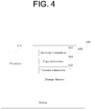
- FIG. 4 is an example block diagram of a computing device 400 including instructions for transferring an address range from a first node to a second node.
- the computing device 400 includes a processor 410 and a machine-readable storage medium 420.
- the machine-readable storage medium 420 further includes instructions 422, 424 and 426 for transferring an address range from a first node (not shown) to a second node (not shown).
- the computing device 400 may be, for example, a secure microprocessor, a notebook computer, a desktop computer, an all-in-one system, a server, a network device, a controller, a wireless device, or any other type of device capable of executing the instructions 422, 424 and 426.
- the computing device 400 may include or be connected to additional components such as memories, controllers, etc.
- the processor 410 may be, at least one central processing unit (CPU), at least one semiconductor-based microprocessor, at least one graphics processing unit (GPU), other hardware devices suitable for retrieval and execution of instructions stored in the machine-readable storage medium 420, or combinations thereof.
- the processor 410 may fetch, decode, and execute instructions 422, 424 and 426 to implement transferring the address range from the first node to a second node.
- the processor 410 may include at least one integrated circuit (IC), other control logic, other electronic circuits, or combinations thereof that include a number of electronic components for performing the functionality of instructions 422, 424 and 426.
- IC integrated circuit
- the machine-readable storage medium 420 may be any electronic, magnetic, optical, or other physical storage device that contains or stores executable instructions.
- the machine-readable storage medium 420 may be, for example, Random Access Memory (RAM), an Electrically Erasable Programmable Read-Only Memory (EEPROM), a storage drive, a Compact Disc Read Only Memory (CD-ROM), and the like.
- RAM Random Access Memory
- EEPROM Electrically Erasable Programmable Read-Only Memory
- CD-ROM Compact Disc Read Only Memory
- the machine-readable storage medium 420 can be non-transitory.
- machine-readable storage medium 420 may be encoded with a series of executable instructions for transferring the address range from the first node to a second node.
- the instructions 422, 424 and 426 when executed by a processor can cause the processor to perform processes, such as, the process of FIG. 4 .
- the generate instructions 422 may be executed by the processor 410 to generate, at the first node, a group address range mapped to a memory address range of a nonvolatile memory (NVM).
- the copy instructions 424 may be executed by the processor 410 to copy, at the first node, a first memory address of the memory address range to a volatile memory (not shown), in response to a write operation for the first memory address that is mapped to the group address range.
- the transfer instructions 426 may be executed by the processor 410 to transfer the group address range from the first node to the second node in response to a synchronization command including a synchronization address range.
- the group address range includes the copied address, where an address external to the synchronization address range and internal to the group address range is to be transferred before the synchronization address range.
- the copied address may be discarded by the first node if the second node does not acknowledge receipt of the group address range within a first threshold period.
- the copied address may be written to the NVM if the second node acknowledges receipt of the group address range with a second threshold period.
- the first node may send a marker to the second node only after the transfer of the group address range is complete.
- the second node may acknowledge the marker in order to acknowledge receipt of the group address range.
- the second node may discard the transferred group address range if the second node does not receive the marker within the second threshold period.
- FIG. 5 is an example flowchart of a method 500 for transferring an address range from a first node to a second node.
- execution of the method 500 is described below with reference to the first node 100, other suitable components for execution of the method 400 can be utilized, such as the first node 200 or 300. Additionally, the components for executing the method 500 may be spread among multiple devices (e.g., a processing device in communication with input and output devices). In certain scenarios, multiple devices acting in coordination can be considered a single device to perform the method 500.
- the method 500 may be implemented in the form of executable instructions stored on a machine-readable storage medium, such as storage medium 420, and/or in the form of electronic circuitry.
- the first node 100 receives a synchronization command including a synchronization address range. Then, at block 520, the first node 100 determines a group address range 114 including the synchronization address range.
- the group address range 114 may be mapped to a memory address range 142 of a NVM 140.
- a first memory address 144 of the memory address range 140 may be copied 132 to a VM 130 if the first memory address 144 is mapped to the group address range 114 and a write access is requested for the first memory address 144. The write access may then be granted to the copied address 132, instead of the first memory address 144.
- the first node 100 transfers the group address range 114 including the synchronization address range to a second node 150, with the synchronization address range to be transferred last.
- the method 500 flows form block 540 to block 550, where the first node 100 transmits a marker to the second node 150. Then, at block 570, the method 500 determines whether the second node 150 acknowledged the marker to the first node 100 within a first threshold period of time. If the marker is not acknowledged, the method 500 flows back to block 560, where the copied address 132 is discarded by the first node 100.
- the method 500 flows from block 570 to block 580, where the first node 100 writes the copied address 132 to the NVM 140.
- the second node 150 may acknowledge the marker after the second node 150 successfully stores an entirety of the transferred group address range 114.
- the second node 150 may discard the transferred group address range 114 if the second node 150 does not receive the marker within a second threshold period of time.
- embodiments may link memory COW operations with groups and/or sub-groups.
- This mechanism of synchronization may be used to implement atomicity within the process of committing multiple COW ranges to a master memory image, such as the NVM.
- a master memory image such as the NVM.
Landscapes
- Engineering & Computer Science (AREA)
- Theoretical Computer Science (AREA)
- General Engineering & Computer Science (AREA)
- Physics & Mathematics (AREA)
- General Physics & Mathematics (AREA)
- Databases & Information Systems (AREA)
- Quality & Reliability (AREA)
- Data Mining & Analysis (AREA)
- Computer Hardware Design (AREA)
- Computing Systems (AREA)
- Library & Information Science (AREA)
- Techniques For Improving Reliability Of Storages (AREA)
- Small-Scale Networks (AREA)
- Information Retrieval, Db Structures And Fs Structures Therefor (AREA)
- Hardware Redundancy (AREA)
Claims (13)
- Premier noeud (100, 200) comprenant :une mémoire volatile (130; 260) ;une table de groupe (110, 210) comprenant un groupe (112) comprenant une pluralité de plages d'adresses de groupe (114, 215, 217) qui sont mappées sur une plage d'adresses de mémoire (142) d'une mémoire non volatile (NVM) (140), chaque plage d'adresses de groupe de la pluralité de plages d'adresses de groupe comprenant une plage de copie sur écriture (COW) (116, 225, 227), avec une première adresse de mémoire (144) de la plage d'adresses de mémoire étant associée à des données à copier dans la mémoire volatile (130, 260) si la première adresse de mémoire est mappée sur la plage COW et qu'un accès en écriture est demandé pour la première adresse de mémoire, chaque plage d'adresses de groupe des plages d'adresses de groupe devant être associée avec l'un d'une pluralité d'indicateurs de disponibilité (219) ; etun contrôleur (120, 250) configuré pour mettre à jour les données copiées dans la mémoire volatile lors de la réception d'une demande d'écriture,dans lequel le contrôleur est en outre configuré pour transférer des données associées à des plages d'adresses de groupe du premier noeud à un second noeud (150, 290) selon un ordre déterminé par la table de groupe, en réponse à une commande de synchronisation, ladite commande de synchronisation comprenant une plage d'adresses de synchronisation, lesdites plages d'adresses de groupes étant déterminées pour être associées à ladite plage d'adresses de synchronisation en utilisant ladite table de groupe,
le contrôleur devant transmettre un marqueur après l'achèvement du transfert,
le contrôleur devant écrire les données copiées dans la mémoire NVM après la reconnaissance du marqueur par le second noeud,
et dans lequel :le contrôleur doit définir l'indicateur de disponibilité d'une plage d'adresses de groupe, si les données associées à la plage d'adresses de groupe doivent être transférées vers le second noeud,le contrôleur doit réinitialiser l'indicateur de disponibilité de toutes les plages d'adresses de groupe sauf la dernière après le transfert de leurs données vers le second noeud, et réinitialiser l'indicateur de disponibilité de l'adresse de groupe dont les données sont transférées en dernier après l'accusé de réception du marqueur par le second noeud et l'écriture des données copiées dans la NVM. - Premier noeud selon la revendication 1, comprenant en outre :un journal (230) pour enregistrer les plages d'adresses de groupe (215, 219) après le transfert des plages d'adresses de groupe au second noeud (290),le journal devant enregistrer le marqueur après le transfert du marqueur vers le second noeud.
- Premier noeud selon la revendication 2, dans lequel le contrôleur (250) doit arrêter et laisser le transfert inachevé si les données copiées sont perdues avant d'être transférées vers le second noeud (290), et
le second noeud doit ignorer la plage d'adresses de groupe transférée du premier noeud (200) si le second noeud ne reçoit pas le marqueur. - Premier noeud selon la revendication 3, dans lequel
le contrôleur (250) doit recevoir les données copiées (262) du second noeud (290), si le transfert est interrompu par une perte de puissance, le marqueur est enregistré dans le journal (230), la plage COW est enregistrée avant le marqueur dans le journal et les données copiées ne sont pas écrites dans la NVM (140). - Premier noeud selon la revendication 2, dans lequel
le contrôleur (250) doit effacer le journal (230) après la réinitialisation de l'indicateur de disponibilité (219) de la dernière plage d'adresses de groupe (215, 217), et
les données copiées (262) sont perdues si le premier noeud (200) perd de la puissance avant l'écriture des données copiées sur la NVM (140). - Premier noeud selon la revendication 1, dans lequel
le contrôleur (250) doit renvoyer le marqueur au second noeud (290) si le second noeud n'accuse pas réception du marqueur, et
le second noeud doit accuser réception du marqueur sur le premier noeud (200) après la réception du marqueur du premier noeud par le second noeud et le stockage de toutes les plages d'adresses de groupe transférées sur le second noeud dans une mémoire NVM accessible par le second noeud. - Premier noeud selon la revendication 3, dans lequel
le contrôleur doit envoyer la dernière plage d'adresses de groupe, si le premier noeud est réinitialisé et que seul l'indicateur de disponibilité de la dernière plage d'adresses de groupe reste défini après la réinitialisation du premier noeud, et
le second noeud doit renvoyer toutes les plages d'adresses de groupe transférées au premier noeud, si le second noeud reçoit la dernière plage d'adresses de groupe après la réception du marqueur. - Premier noeud selon la revendication 1, dans lequel
le premier noeud (200) doit ignorer les données copiées (262) si le marqueur n'est pas reconnu par le second noeud (290) après au moins l'un d'une première période seuil (270) et d'un premier nombre de seuils (280) de retransmissions du marqueur au second noeud, et
le second noeud doit ignorer la plage d'adresses de groupe transférée depuis le premier noeud, si le second noeud ne reçoit pas le marqueur après au moins l'un d'une seconde période seuil et d'un second nombre de retransmissions d'un accusé-réception de la plage d'adresses de groupe reçue en dernier par le second noeud. - Premier noeud selon la revendication 1, dans lequel
les données copiées (262) sont modifiées en réponse à un accès en écriture pour la première adresse de mémoire, et
le contrôleur (250) doit écrire les données copiées sur la première adresse de mémoire (14) de la NVM (140) après la reconnaissance du marqueur par le second noeud. - Procédé (500) comprenant :au niveau d'un premier noeud (100, 200), comprenant une table de groupe (110, 210), comprenant un groupe (112) associé à des plages d'adresses de groupe (114, 215, 217), chacune des plages d'adresses de groupe étant associées à un indicateur de disponibilité (219) d'une pluralité d'indicateurs de disponibilité (219), chacune desdites plages d'adresses de groupe devant être mappée sur une plage d'adresses de mémoire (142) d'une mémoire non volatile (NVM) (140), chaque plage d'adresses de groupe comprenant une plage de copie sur écriture (COW) (116, 225, 227), avec une première adresse de mémoire (144) de la plage d'adresses de mémoire étant associée à des données à copier dans une mémoire volatile (130, 260) si la première adresse de mémoire est mappée sur la plage d'adresses de groupe COW et qu'un accès en écriture est demandé pour la première adresse de mémoire, avec l'accès en écriture étant accordé aux données copiées (132, 162), et la mise à jour les données copiées dans la mémoire volatile lors de la réception d'une demande d'écriture, la réception (510) d'une commande de synchronisation comprenant une plage d'adresses de synchronisation ;la détermination (520), au niveau du premier noeud, des plages d'adresses de groupe correspondant à la plage d'adresses de synchronisation, en utilisant ladite table de groupe ;le transfert (530) des données associées à chacune des plages d'adresses de groupes déterminées du premier noeud à un second noeud (150, 290) selon un ordre déterminé par la table de groupes, les données incluant la plage d'adresses de synchronisation ;la transmission (550) d'un marqueur du premier noeud au second noeud après l'achèvement du transfert ; etl'écriture (580) des données copiées (232, 262) dans la mémoire NVM si le second noeud accuse réception du marqueur ;le fait d'ignorer (560) les données copiées si au moins l'un du transfert n'est pas terminé et du second noeud n'accuse pas réception du marqueur après une première période seuil,
le procédé comprenant en outre :la définition de l'indicateur de disponibilité d'une plage d'adresses de groupe, si les données associées à la plage d'adresses de groupe doivent être transférées vers le second noeud, etla réinitialisation de l'indicateur de disponibilité de toutes les plages d'adresses de groupe déterminées sauf la dernière après le transfert de leurs données respectives vers le second noeud, et la réinitialisation de l'indicateur de disponibilité de la plage d'adresses de groupe dont les données sont transférées en dernier après l'accusation de réception du marqueur par le second noeud et l'écriture des données copiées dans la NVM. - Procédé selon la revendication 10, dans lequel
le second noeud (290) reconnaît le marqueur après le stockage avec succès par le second noeud de la totalité des données transférées, et
le second noeud ignore les données transférées si le second noeud ne reçoit pas le marqueur dans une seconde période seuil. - Support de stockage lisible par ordinateur non transitoire (420) stockant des instructions qui, si elles sont exécutées par un processeur (400) d'un dispositif (410), amènent le processeur à exécuter les étapes du procédé selon la revendication 10.
- Support de stockage lisible par ordinateur non transitoire selon la revendication 12, dans lequel
le premier noeud (200) doit envoyer le marqueur au second noeud (290) uniquement après l'achèvement du transfert de la plage d'adresses de groupe (215, 217),
le second noeud doit reconnaître le marqueur pour accuser réception de la plage d'adresses de groupe, et
le second noeud doit ignorer la plage d'adresses de groupe transférée si le second noeud ne reçoit pas le marqueur dans la seconde période seuil.
Applications Claiming Priority (1)
| Application Number | Priority Date | Filing Date | Title |
|---|---|---|---|
| PCT/US2013/034382 WO2014158166A1 (fr) | 2013-03-28 | 2013-03-28 | Transfert de plage d'adresses d'un premier nœud à un deuxième nœud |
Publications (3)
| Publication Number | Publication Date |
|---|---|
| EP2979185A1 EP2979185A1 (fr) | 2016-02-03 |
| EP2979185A4 EP2979185A4 (fr) | 2016-10-19 |
| EP2979185B1 true EP2979185B1 (fr) | 2019-01-30 |
Family
ID=51624948
Family Applications (1)
| Application Number | Title | Priority Date | Filing Date |
|---|---|---|---|
| EP13879713.9A Active EP2979185B1 (fr) | 2013-03-28 | 2013-03-28 | Transfert de plage d'adresses d'un premier noeud à un deuxième noeud |
Country Status (5)
| Country | Link |
|---|---|
| US (1) | US9703701B2 (fr) |
| EP (1) | EP2979185B1 (fr) |
| CN (1) | CN104937565B (fr) |
| TW (1) | TW201502778A (fr) |
| WO (1) | WO2014158166A1 (fr) |
Families Citing this family (9)
| Publication number | Priority date | Publication date | Assignee | Title |
|---|---|---|---|---|
| US10019403B2 (en) * | 2015-11-04 | 2018-07-10 | International Business Machines Corporation | Mapping data locations using data transmissions |
| CN106919531B (zh) * | 2015-12-25 | 2020-02-21 | 华为技术有限公司 | 基于非易失性存储总线协议的交互方法及设备 |
| US10795782B2 (en) | 2018-04-02 | 2020-10-06 | Hewlett Packard Enterprise Development Lp | Data processing apparatuses and methods to support transferring control between a primary data processing system and a secondary data processing system in response to an event |
| TWI696951B (zh) * | 2018-08-31 | 2020-06-21 | 威剛科技股份有限公司 | 儲存裝置異常斷電的處理系統和方法 |
| US11544093B2 (en) * | 2019-09-27 | 2023-01-03 | Intel Corporation | Virtual machine replication and migration |
| US10990526B1 (en) | 2020-04-30 | 2021-04-27 | Micron Technology, Inc. | Handling asynchronous power loss in a memory sub-system that programs sequentially |
| CN112507032B (zh) * | 2020-12-22 | 2022-05-27 | 正链科技(深圳)有限公司 | 一种kademlia协议的k-桶构造改进方法 |
| US12314178B2 (en) * | 2020-12-26 | 2025-05-27 | Intel Corporation | Management of distributed shared memory |
| CN115589429B (zh) * | 2022-09-28 | 2025-06-27 | 苏州浪潮智能科技有限公司 | 一种非易失性存储器的设备连接方法、装置、设备及介质 |
Citations (1)
| Publication number | Priority date | Publication date | Assignee | Title |
|---|---|---|---|---|
| US20070022264A1 (en) * | 2005-07-14 | 2007-01-25 | Yottayotta, Inc. | Maintaining write order fidelity on a multi-writer system |
Family Cites Families (33)
| Publication number | Priority date | Publication date | Assignee | Title |
|---|---|---|---|---|
| US5963962A (en) | 1995-05-31 | 1999-10-05 | Network Appliance, Inc. | Write anywhere file-system layout |
| US6360231B1 (en) * | 1999-02-26 | 2002-03-19 | Hewlett-Packard Company | Transactional memory for distributed shared memory multi-processor computer systems |
| US6658540B1 (en) * | 2000-03-31 | 2003-12-02 | Hewlett-Packard Development Company, L.P. | Method for transaction command ordering in a remote data replication system |
| US6728736B2 (en) | 2001-03-14 | 2004-04-27 | Storage Technology Corporation | System and method for synchronizing a data copy using an accumulation remote copy trio |
| US6789156B1 (en) | 2001-05-22 | 2004-09-07 | Vmware, Inc. | Content-based, transparent sharing of memory units |
| US7133982B2 (en) | 2003-06-18 | 2006-11-07 | International Business Machines Corporation | Method, system, and article of manufacture for consistent copying of storage volumes |
| DE60322387D1 (de) | 2003-08-27 | 2008-09-04 | Advanced Risc Mach Ltd | Vorrichtung und Verfahren zur Verwaltung von Transaktionen zum Schreiben und Lesen auf EEPROM-Speicher oder Flash-Speicher |
| US7133986B2 (en) | 2003-09-29 | 2006-11-07 | International Business Machines Corporation | Method, system, and program for forming a consistency group |
| US7173863B2 (en) | 2004-03-08 | 2007-02-06 | Sandisk Corporation | Flash controller cache architecture |
| JP2005310008A (ja) | 2004-04-23 | 2005-11-04 | Fuji Xerox Co Ltd | 木構造データ同期装置および方法 |
| US7644239B2 (en) | 2004-05-03 | 2010-01-05 | Microsoft Corporation | Non-volatile memory cache performance improvement |
| US7975018B2 (en) * | 2004-07-07 | 2011-07-05 | Emc Corporation | Systems and methods for providing distributed cache coherence |
| US7818515B1 (en) | 2004-08-10 | 2010-10-19 | Symantec Operating Corporation | System and method for enforcing device grouping rules for storage virtualization |
| WO2006095335A2 (fr) | 2005-03-07 | 2006-09-14 | Noam Camiel | Systeme et procede pour systeme de fichiers a renforcement de politique dynamique pour un dispositif de stockage de donnees |
| US7464126B2 (en) | 2005-07-21 | 2008-12-09 | International Business Machines Corporation | Method for creating an application-consistent remote copy of data using remote mirroring |
| US9032164B2 (en) | 2006-02-17 | 2015-05-12 | Emulex Corporation | Apparatus for performing storage virtualization |
| US7640395B2 (en) | 2006-03-30 | 2009-12-29 | Intel Corporation | Maintaining write ordering in a system |
| US7788231B2 (en) | 2006-04-18 | 2010-08-31 | International Business Machines Corporation | Using a heartbeat signal to maintain data consistency for writes to source storage copied to target storage |
| US7647454B2 (en) * | 2006-06-12 | 2010-01-12 | Hewlett-Packard Development Company, L.P. | Transactional shared memory system and method of control |
| EP2211271A3 (fr) | 2006-07-31 | 2011-04-27 | Kabushiki Kaisha Toshiba | Memoire non volatile et sa méthode d'écriture et de lecture |
| US7975109B2 (en) | 2007-05-30 | 2011-07-05 | Schooner Information Technology, Inc. | System including a fine-grained memory and a less-fine-grained memory |
| US20090063807A1 (en) | 2007-08-29 | 2009-03-05 | International Business Machines Corporation | Data redistribution in shared nothing architecture |
| JP5101378B2 (ja) | 2008-04-16 | 2012-12-19 | ソニー株式会社 | リーダライタ、通信処理装置、通信処理方法、データ管理システム及び通信システム |
| US8099387B2 (en) | 2008-06-02 | 2012-01-17 | International Business Machines Corporation | Managing consistency groups using heterogeneous replication engines |
| JPWO2010001602A1 (ja) | 2008-07-01 | 2011-12-15 | パナソニック株式会社 | メモリコントローラ、不揮発性記憶装置、データ処理装置、不揮発性記憶装置システム及び方法 |
| JP5221332B2 (ja) | 2008-12-27 | 2013-06-26 | 株式会社東芝 | メモリシステム |
| US8762642B2 (en) | 2009-01-30 | 2014-06-24 | Twinstrata Inc | System and method for secure and reliable multi-cloud data replication |
| US8219776B2 (en) | 2009-09-23 | 2012-07-10 | Lsi Corporation | Logical-to-physical address translation for solid state disks |
| US8438332B2 (en) | 2009-06-22 | 2013-05-07 | International Business Machines Corporation | Apparatus and method to maintain write operation atomicity where a data transfer operation crosses a data storage medium track boundary |
| US9063886B2 (en) | 2009-09-18 | 2015-06-23 | Apple Inc. | Metadata redundancy schemes for non-volatile memories |
| US9053027B1 (en) * | 2011-12-21 | 2015-06-09 | Emc Corporation | Techniques for maintaining and restoring dirty caches across CPU resets |
| US9678863B2 (en) * | 2012-06-12 | 2017-06-13 | Sandisk Technologies, Llc | Hybrid checkpointed memory |
| US20140075086A1 (en) * | 2012-09-13 | 2014-03-13 | International Business Machines Corporation | Durable transactions with storage-class memory |
-
2013
- 2013-03-28 US US14/765,057 patent/US9703701B2/en active Active
- 2013-03-28 CN CN201380071543.6A patent/CN104937565B/zh active Active
- 2013-03-28 WO PCT/US2013/034382 patent/WO2014158166A1/fr not_active Ceased
- 2013-03-28 EP EP13879713.9A patent/EP2979185B1/fr active Active
-
2014
- 2014-03-27 TW TW103111472A patent/TW201502778A/zh unknown
Patent Citations (1)
| Publication number | Priority date | Publication date | Assignee | Title |
|---|---|---|---|---|
| US20070022264A1 (en) * | 2005-07-14 | 2007-01-25 | Yottayotta, Inc. | Maintaining write order fidelity on a multi-writer system |
Also Published As
| Publication number | Publication date |
|---|---|
| US20150370702A1 (en) | 2015-12-24 |
| EP2979185A1 (fr) | 2016-02-03 |
| CN104937565A (zh) | 2015-09-23 |
| CN104937565B (zh) | 2017-11-17 |
| EP2979185A4 (fr) | 2016-10-19 |
| US9703701B2 (en) | 2017-07-11 |
| WO2014158166A1 (fr) | 2014-10-02 |
| TW201502778A (zh) | 2015-01-16 |
Similar Documents
| Publication | Publication Date | Title |
|---|---|---|
| US9703701B2 (en) | Address range transfer from first node to second node | |
| US8407435B2 (en) | Efficiently creating a snapshot of a large consistency group using multiple commands including a snapshot preparation command | |
| US8341115B1 (en) | Dynamically switching between synchronous and asynchronous replication | |
| US9183103B2 (en) | Lightweight remote replication of a local write-back cache | |
| US10620842B1 (en) | Maintaining write consistency on distributed multiple page writes | |
| CN109582495B (zh) | 数据存储系统、存储阵列及非暂态机器可读介质 | |
| EP2979187B1 (fr) | Vidage de données d'une table de groupe | |
| US20180095914A1 (en) | Application direct access to sata drive | |
| US20170242822A1 (en) | Dram appliance for data persistence | |
| WO2015191048A1 (fr) | Réplication de données utilisant un accès direct à la mémoire à distance (rdma) | |
| KR20150129839A (ko) | 분산 데이터 시스템들을 위한 전 시스템에 미치는 체크포인트 회피 | |
| US20150261461A1 (en) | High performance persistent memory | |
| US20190141128A1 (en) | Scalable storage system | |
| US10210060B2 (en) | Online NVM format upgrade in a data storage system operating with active and standby memory controllers | |
| EP3679478A1 (fr) | Système de stockage évolutif | |
| CN114201109B (zh) | 计算系统、介质以及用于计算系统的方法 | |
| US20200250147A1 (en) | Managing replica unavailibility in a distributed file system | |
| JP2013250886A (ja) | 仮想マシンのメモリ複製装置及び方法及びプログラム |
Legal Events
| Date | Code | Title | Description |
|---|---|---|---|
| PUAI | Public reference made under article 153(3) epc to a published international application that has entered the european phase |
Free format text: ORIGINAL CODE: 0009012 |
|
| 17P | Request for examination filed |
Effective date: 20150728 |
|
| AK | Designated contracting states |
Kind code of ref document: A1 Designated state(s): AL AT BE BG CH CY CZ DE DK EE ES FI FR GB GR HR HU IE IS IT LI LT LU LV MC MK MT NL NO PL PT RO RS SE SI SK SM TR |
|
| AX | Request for extension of the european patent |
Extension state: BA ME |
|
| RAP1 | Party data changed (applicant data changed or rights of an application transferred) |
Owner name: HEWLETT PACKARD ENTERPRISE DEVELOPMENT L.P. |
|
| DAX | Request for extension of the european patent (deleted) | ||
| A4 | Supplementary search report drawn up and despatched |
Effective date: 20160921 |
|
| RIC1 | Information provided on ipc code assigned before grant |
Ipc: G06F 13/40 20060101ALI20160915BHEP Ipc: G06F 12/02 20060101AFI20160915BHEP Ipc: G06F 13/14 20060101ALI20160915BHEP Ipc: G11C 16/22 20060101ALI20160915BHEP Ipc: G06F 17/30 20060101ALI20160915BHEP Ipc: G11C 16/06 20060101ALI20160915BHEP Ipc: G06F 11/20 20060101ALI20160915BHEP Ipc: G06F 12/0804 20160101ALI20160915BHEP Ipc: G06F 11/14 20060101ALI20160915BHEP Ipc: G06F 12/0868 20160101ALI20160915BHEP Ipc: G06F 11/07 20060101ALI20160915BHEP |
|
| STAA | Information on the status of an ep patent application or granted ep patent |
Free format text: STATUS: EXAMINATION IS IN PROGRESS |
|
| 17Q | First examination report despatched |
Effective date: 20171211 |
|
| GRAP | Despatch of communication of intention to grant a patent |
Free format text: ORIGINAL CODE: EPIDOSNIGR1 |
|
| STAA | Information on the status of an ep patent application or granted ep patent |
Free format text: STATUS: GRANT OF PATENT IS INTENDED |
|
| INTG | Intention to grant announced |
Effective date: 20180301 |
|
| GRAJ | Information related to disapproval of communication of intention to grant by the applicant or resumption of examination proceedings by the epo deleted |
Free format text: ORIGINAL CODE: EPIDOSDIGR1 |
|
| STAA | Information on the status of an ep patent application or granted ep patent |
Free format text: STATUS: EXAMINATION IS IN PROGRESS |
|
| INTC | Intention to grant announced (deleted) | ||
| GRAP | Despatch of communication of intention to grant a patent |
Free format text: ORIGINAL CODE: EPIDOSNIGR1 |
|
| STAA | Information on the status of an ep patent application or granted ep patent |
Free format text: STATUS: GRANT OF PATENT IS INTENDED |
|
| INTG | Intention to grant announced |
Effective date: 20180813 |
|
| GRAS | Grant fee paid |
Free format text: ORIGINAL CODE: EPIDOSNIGR3 |
|
| GRAA | (expected) grant |
Free format text: ORIGINAL CODE: 0009210 |
|
| STAA | Information on the status of an ep patent application or granted ep patent |
Free format text: STATUS: THE PATENT HAS BEEN GRANTED |
|
| AK | Designated contracting states |
Kind code of ref document: B1 Designated state(s): AL AT BE BG CH CY CZ DE DK EE ES FI FR GB GR HR HU IE IS IT LI LT LU LV MC MK MT NL NO PL PT RO RS SE SI SK SM TR |
|
| REG | Reference to a national code |
Ref country code: GB Ref legal event code: FG4D |
|
| REG | Reference to a national code |
Ref country code: CH Ref legal event code: EP |
|
| RIC2 | Information provided on ipc code assigned after grant |
Ipc: G06F 11/07 20060101ALI20160915BHEP Ipc: G06F 17/30 20060101ALI20160915BHEP Ipc: G06F 11/14 20060101ALI20160915BHEP Ipc: G06F 12/02 20060101AFI20160915BHEP Ipc: G11C 16/22 20060101ALI20160915BHEP Ipc: G06F 12/0868 20160101ALI20160915BHEP Ipc: G06F 12/0804 20160101ALI20160915BHEP Ipc: G06F 13/14 20060101ALI20160915BHEP Ipc: G11C 16/06 20060101ALI20160915BHEP Ipc: G06F 11/20 20060101ALI20160915BHEP Ipc: G06F 13/40 20060101ALI20160915BHEP |
|
| REG | Reference to a national code |
Ref country code: AT Ref legal event code: REF Ref document number: 1093815 Country of ref document: AT Kind code of ref document: T Effective date: 20190215 |
|
| REG | Reference to a national code |
Ref country code: IE Ref legal event code: FG4D |
|
| REG | Reference to a national code |
Ref country code: DE Ref legal event code: R096 Ref document number: 602013050397 Country of ref document: DE |
|
| PGFP | Annual fee paid to national office [announced via postgrant information from national office to epo] |
Ref country code: FR Payment date: 20190219 Year of fee payment: 7 |
|
| REG | Reference to a national code |
Ref country code: LT Ref legal event code: MG4D |
|
| REG | Reference to a national code |
Ref country code: NL Ref legal event code: MP Effective date: 20190130 |
|
| PG25 | Lapsed in a contracting state [announced via postgrant information from national office to epo] |
Ref country code: PT Free format text: LAPSE BECAUSE OF FAILURE TO SUBMIT A TRANSLATION OF THE DESCRIPTION OR TO PAY THE FEE WITHIN THE PRESCRIBED TIME-LIMIT Effective date: 20190530 Ref country code: SE Free format text: LAPSE BECAUSE OF FAILURE TO SUBMIT A TRANSLATION OF THE DESCRIPTION OR TO PAY THE FEE WITHIN THE PRESCRIBED TIME-LIMIT Effective date: 20190130 Ref country code: FI Free format text: LAPSE BECAUSE OF FAILURE TO SUBMIT A TRANSLATION OF THE DESCRIPTION OR TO PAY THE FEE WITHIN THE PRESCRIBED TIME-LIMIT Effective date: 20190130 Ref country code: NO Free format text: LAPSE BECAUSE OF FAILURE TO SUBMIT A TRANSLATION OF THE DESCRIPTION OR TO PAY THE FEE WITHIN THE PRESCRIBED TIME-LIMIT Effective date: 20190430 Ref country code: NL Free format text: LAPSE BECAUSE OF FAILURE TO SUBMIT A TRANSLATION OF THE DESCRIPTION OR TO PAY THE FEE WITHIN THE PRESCRIBED TIME-LIMIT Effective date: 20190130 Ref country code: PL Free format text: LAPSE BECAUSE OF FAILURE TO SUBMIT A TRANSLATION OF THE DESCRIPTION OR TO PAY THE FEE WITHIN THE PRESCRIBED TIME-LIMIT Effective date: 20190130 Ref country code: LT Free format text: LAPSE BECAUSE OF FAILURE TO SUBMIT A TRANSLATION OF THE DESCRIPTION OR TO PAY THE FEE WITHIN THE PRESCRIBED TIME-LIMIT Effective date: 20190130 Ref country code: ES Free format text: LAPSE BECAUSE OF FAILURE TO SUBMIT A TRANSLATION OF THE DESCRIPTION OR TO PAY THE FEE WITHIN THE PRESCRIBED TIME-LIMIT Effective date: 20190130 |
|
| REG | Reference to a national code |
Ref country code: AT Ref legal event code: MK05 Ref document number: 1093815 Country of ref document: AT Kind code of ref document: T Effective date: 20190130 |
|
| PG25 | Lapsed in a contracting state [announced via postgrant information from national office to epo] |
Ref country code: IS Free format text: LAPSE BECAUSE OF FAILURE TO SUBMIT A TRANSLATION OF THE DESCRIPTION OR TO PAY THE FEE WITHIN THE PRESCRIBED TIME-LIMIT Effective date: 20190530 Ref country code: HR Free format text: LAPSE BECAUSE OF FAILURE TO SUBMIT A TRANSLATION OF THE DESCRIPTION OR TO PAY THE FEE WITHIN THE PRESCRIBED TIME-LIMIT Effective date: 20190130 Ref country code: GR Free format text: LAPSE BECAUSE OF FAILURE TO SUBMIT A TRANSLATION OF THE DESCRIPTION OR TO PAY THE FEE WITHIN THE PRESCRIBED TIME-LIMIT Effective date: 20190501 Ref country code: LV Free format text: LAPSE BECAUSE OF FAILURE TO SUBMIT A TRANSLATION OF THE DESCRIPTION OR TO PAY THE FEE WITHIN THE PRESCRIBED TIME-LIMIT Effective date: 20190130 Ref country code: RS Free format text: LAPSE BECAUSE OF FAILURE TO SUBMIT A TRANSLATION OF THE DESCRIPTION OR TO PAY THE FEE WITHIN THE PRESCRIBED TIME-LIMIT Effective date: 20190130 Ref country code: BG Free format text: LAPSE BECAUSE OF FAILURE TO SUBMIT A TRANSLATION OF THE DESCRIPTION OR TO PAY THE FEE WITHIN THE PRESCRIBED TIME-LIMIT Effective date: 20190430 |
|
| PG25 | Lapsed in a contracting state [announced via postgrant information from national office to epo] |
Ref country code: CZ Free format text: LAPSE BECAUSE OF FAILURE TO SUBMIT A TRANSLATION OF THE DESCRIPTION OR TO PAY THE FEE WITHIN THE PRESCRIBED TIME-LIMIT Effective date: 20190130 Ref country code: IT Free format text: LAPSE BECAUSE OF FAILURE TO SUBMIT A TRANSLATION OF THE DESCRIPTION OR TO PAY THE FEE WITHIN THE PRESCRIBED TIME-LIMIT Effective date: 20190130 Ref country code: RO Free format text: LAPSE BECAUSE OF FAILURE TO SUBMIT A TRANSLATION OF THE DESCRIPTION OR TO PAY THE FEE WITHIN THE PRESCRIBED TIME-LIMIT Effective date: 20190130 Ref country code: EE Free format text: LAPSE BECAUSE OF FAILURE TO SUBMIT A TRANSLATION OF THE DESCRIPTION OR TO PAY THE FEE WITHIN THE PRESCRIBED TIME-LIMIT Effective date: 20190130 Ref country code: DK Free format text: LAPSE BECAUSE OF FAILURE TO SUBMIT A TRANSLATION OF THE DESCRIPTION OR TO PAY THE FEE WITHIN THE PRESCRIBED TIME-LIMIT Effective date: 20190130 Ref country code: MC Free format text: LAPSE BECAUSE OF FAILURE TO SUBMIT A TRANSLATION OF THE DESCRIPTION OR TO PAY THE FEE WITHIN THE PRESCRIBED TIME-LIMIT Effective date: 20190130 Ref country code: AL Free format text: LAPSE BECAUSE OF FAILURE TO SUBMIT A TRANSLATION OF THE DESCRIPTION OR TO PAY THE FEE WITHIN THE PRESCRIBED TIME-LIMIT Effective date: 20190130 Ref country code: SK Free format text: LAPSE BECAUSE OF FAILURE TO SUBMIT A TRANSLATION OF THE DESCRIPTION OR TO PAY THE FEE WITHIN THE PRESCRIBED TIME-LIMIT Effective date: 20190130 |
|
| REG | Reference to a national code |
Ref country code: CH Ref legal event code: PL Ref country code: DE Ref legal event code: R097 Ref document number: 602013050397 Country of ref document: DE |
|
| PG25 | Lapsed in a contracting state [announced via postgrant information from national office to epo] |
Ref country code: LU Free format text: LAPSE BECAUSE OF NON-PAYMENT OF DUE FEES Effective date: 20190328 Ref country code: SM Free format text: LAPSE BECAUSE OF FAILURE TO SUBMIT A TRANSLATION OF THE DESCRIPTION OR TO PAY THE FEE WITHIN THE PRESCRIBED TIME-LIMIT Effective date: 20190130 |
|
| REG | Reference to a national code |
Ref country code: BE Ref legal event code: MM Effective date: 20190331 |
|
| PLBE | No opposition filed within time limit |
Free format text: ORIGINAL CODE: 0009261 |
|
| STAA | Information on the status of an ep patent application or granted ep patent |
Free format text: STATUS: NO OPPOSITION FILED WITHIN TIME LIMIT |
|
| PG25 | Lapsed in a contracting state [announced via postgrant information from national office to epo] |
Ref country code: AT Free format text: LAPSE BECAUSE OF FAILURE TO SUBMIT A TRANSLATION OF THE DESCRIPTION OR TO PAY THE FEE WITHIN THE PRESCRIBED TIME-LIMIT Effective date: 20190130 |
|
| 26N | No opposition filed |
Effective date: 20191031 |
|
| PG25 | Lapsed in a contracting state [announced via postgrant information from national office to epo] |
Ref country code: LI Free format text: LAPSE BECAUSE OF NON-PAYMENT OF DUE FEES Effective date: 20190331 Ref country code: CH Free format text: LAPSE BECAUSE OF NON-PAYMENT OF DUE FEES Effective date: 20190331 Ref country code: IE Free format text: LAPSE BECAUSE OF NON-PAYMENT OF DUE FEES Effective date: 20190328 |
|
| PG25 | Lapsed in a contracting state [announced via postgrant information from national office to epo] |
Ref country code: SI Free format text: LAPSE BECAUSE OF FAILURE TO SUBMIT A TRANSLATION OF THE DESCRIPTION OR TO PAY THE FEE WITHIN THE PRESCRIBED TIME-LIMIT Effective date: 20190130 Ref country code: BE Free format text: LAPSE BECAUSE OF NON-PAYMENT OF DUE FEES Effective date: 20190331 |
|
| PG25 | Lapsed in a contracting state [announced via postgrant information from national office to epo] |
Ref country code: TR Free format text: LAPSE BECAUSE OF FAILURE TO SUBMIT A TRANSLATION OF THE DESCRIPTION OR TO PAY THE FEE WITHIN THE PRESCRIBED TIME-LIMIT Effective date: 20190130 |
|
| PG25 | Lapsed in a contracting state [announced via postgrant information from national office to epo] |
Ref country code: MT Free format text: LAPSE BECAUSE OF NON-PAYMENT OF DUE FEES Effective date: 20190328 |
|
| PG25 | Lapsed in a contracting state [announced via postgrant information from national office to epo] |
Ref country code: FR Free format text: LAPSE BECAUSE OF NON-PAYMENT OF DUE FEES Effective date: 20200331 |
|
| PG25 | Lapsed in a contracting state [announced via postgrant information from national office to epo] |
Ref country code: CY Free format text: LAPSE BECAUSE OF FAILURE TO SUBMIT A TRANSLATION OF THE DESCRIPTION OR TO PAY THE FEE WITHIN THE PRESCRIBED TIME-LIMIT Effective date: 20190130 |
|
| PG25 | Lapsed in a contracting state [announced via postgrant information from national office to epo] |
Ref country code: HU Free format text: LAPSE BECAUSE OF FAILURE TO SUBMIT A TRANSLATION OF THE DESCRIPTION OR TO PAY THE FEE WITHIN THE PRESCRIBED TIME-LIMIT; INVALID AB INITIO Effective date: 20130328 |
|
| PG25 | Lapsed in a contracting state [announced via postgrant information from national office to epo] |
Ref country code: MK Free format text: LAPSE BECAUSE OF FAILURE TO SUBMIT A TRANSLATION OF THE DESCRIPTION OR TO PAY THE FEE WITHIN THE PRESCRIBED TIME-LIMIT Effective date: 20190130 |
|
| REG | Reference to a national code |
Ref country code: DE Ref legal event code: R081 Ref document number: 602013050397 Country of ref document: DE Owner name: HEWLETT PACKARD ENTERPRISE DEVELOPMENT LP, SPR, US Free format text: FORMER OWNER: HEWLETT PACKARD ENTERPRISE DEVELOPMENT LP, HOUSTON, TEX., US Ref country code: DE Ref legal event code: R082 Ref document number: 602013050397 Country of ref document: DE Representative=s name: MARKS & CLERK (LUXEMBOURG) LLP, LU |
|
| PGFP | Annual fee paid to national office [announced via postgrant information from national office to epo] |
Ref country code: GB Payment date: 20260326 Year of fee payment: 14 |
|
| PGFP | Annual fee paid to national office [announced via postgrant information from national office to epo] |
Ref country code: DE Payment date: 20260326 Year of fee payment: 14 |