EP2979529A1 - Machine agricole repliable - Google Patents
Machine agricole repliable Download PDFInfo
- Publication number
- EP2979529A1 EP2979529A1 EP15179387.4A EP15179387A EP2979529A1 EP 2979529 A1 EP2979529 A1 EP 2979529A1 EP 15179387 A EP15179387 A EP 15179387A EP 2979529 A1 EP2979529 A1 EP 2979529A1
- Authority
- EP
- European Patent Office
- Prior art keywords
- central frame
- bearing
- agricultural machine
- boom
- cantilever
- Prior art date
- Legal status (The legal status is an assumption and is not a legal conclusion. Google has not performed a legal analysis and makes no representation as to the accuracy of the status listed.)
- Granted
Links
Images



Classifications
-
- A—HUMAN NECESSITIES
- A01—AGRICULTURE; FORESTRY; ANIMAL HUSBANDRY; HUNTING; TRAPPING; FISHING
- A01B—SOIL WORKING IN AGRICULTURE OR FORESTRY; PARTS, DETAILS, OR ACCESSORIES OF AGRICULTURAL MACHINES OR IMPLEMENTS, IN GENERAL
- A01B73/00—Means or arrangements to facilitate transportation of agricultural machines or implements, e.g. folding frames to reduce overall width
- A01B73/02—Folding frames
- A01B73/06—Folding frames foldable about a vertical axis
- A01B73/065—Folding frames foldable about a vertical axis to a position essentially forward of the axis, in relation to the direction of travel
-
- A—HUMAN NECESSITIES
- A01—AGRICULTURE; FORESTRY; ANIMAL HUSBANDRY; HUNTING; TRAPPING; FISHING
- A01B—SOIL WORKING IN AGRICULTURE OR FORESTRY; PARTS, DETAILS, OR ACCESSORIES OF AGRICULTURAL MACHINES OR IMPLEMENTS, IN GENERAL
- A01B73/00—Means or arrangements to facilitate transportation of agricultural machines or implements, e.g. folding frames to reduce overall width
- A01B73/02—Folding frames
- A01B73/04—Folding frames foldable about a horizontal axis
- A01B73/048—Folding frames foldable about a horizontal axis the axis being oriented in transverse direction
-
- A—HUMAN NECESSITIES
- A01—AGRICULTURE; FORESTRY; ANIMAL HUSBANDRY; HUNTING; TRAPPING; FISHING
- A01D—HARVESTING; MOWING
- A01D84/00—Haymakers not provided for in a single one of groups A01D76/00 - A01D82/00
Definitions
- the invention relates to a collapsible agricultural machine according to the preamble of claim 1.
- a generic agricultural machine in the form of a band rake or merger is the DE 60 2004 009 338 T2 or the US 7,310,929 B2 refer to.
- an agricultural machine for processing grassland comprises a machine frame comprising a drawbar for connection to a tractor and a central frame supported by main wheels for the drawbar.
- the main wheels carry the central frame both in a transport and in a working position.
- at least one cantilever arm is connected to the central frame via a cantilever bearing, wherein the cantilever bearing defines a cantilever bearing axis.
- At least one working tool is arranged on the cantilever arm, wherein the working tool is rotatably mounted with the cantilever arm about the cantilever bearing axis. The floor adjustment via the boom in working position by pivoting about the boom bearing axis.
- the central frame is connected via a central frame bearing, which defines a central frame bearing axis, with the drawbar, whereby the central frame is rotatably arranged about the central frame bearing axis to the drawbar, the central frame in a first working position associated with a pivot position and a second assigned to a transport position Pivoting position can be brought, in particular in the respective position can be locked.
- the central frame bearing can be designed so that the central frame bearing axis is aligned parallel to the wheel axis of the main wheels.
- the main wheels are connected to the central frame in such a way that upon pivoting of the central frame, the main wheels follow the pivotal movement of the central frame, so that the main wheels are pivoted to the central frame about the central frame bearing axis.
- the central frame may preferably be formed in a U-shaped basic design.
- the wheels are preferably arranged on the floor facing the open end of the central frame.
- This arrangement ensures a particularly high clearance height for lying in the middle of the agricultural machine or stored crop, which accumulation can be avoided.
- the cantilever bearing axis is in particular orthogonal to the central frame bearing axis.
- the boom bearing is preferably arranged in the vertical direction between the wheel suspension and the central frame bearing. This allows the passage height in the area of the boom bearing to be as large as possible.
- the boom bearing can lie in the horizontal transverse direction between the drawbar and the main wheel. As a result, a maximum clearance height can be achieved with minimal transport width.
- the boom bearing extends over a majority of the extension of the central frame in the direction of travel.
- the cantilever bearing may comprise a plurality of pivot bearings.
- the boom bearing has an axial extent of 500 mm to 1000 mm.
- the axial extent of the cantilever bearing describes the extent to which transverse forces can be absorbed by the cantilever bearing.
- a cantilever bearing may include a plurality of pivot bearings disposed about the same cantilever bearing axis. The boom expansion then refers to the farthest spaced pivot bearings.
- the cantilever arm is designed such that it is guided around one side of the arranged on the central frame main wheel. As a result, a particularly low transport height can be achieved.
- the cantilever bearing may be designed such that it has a rod-shaped axle arranged on the central frame, which is enclosed by a tube arranged on the cantilever arm.
- the cantilever bearing is designed in the manner of a sliding bearing. It is also conceivable to integrate rolling bearings, which are arranged at a distance, in this arrangement.
- a cantilever wheel in particular fixed, can be arranged on the cantilever arm.
- This provides for improved ground contouring of the work tools disposed on the boom, with the weighting forces being able to be partially absorbed by the boom wheel.
- This eliminates the need for a boom relief structure. Even on follower wheels can be dispensed with by such an arrangement.
- the cantilever wheel may preferably be arranged on the end remote from the central frame of the cantilever arm. This represents a particularly simple and efficient way of fastening and still ensures ideal floor guidance.
- the cantilever may be offset from the main wheel in the direction of travel, that in the working position, the main wheel projects beyond the cantilever wheel counter to the direction of travel. In this way, the folding operation can be performed without prior adjustment of the cantilever wheel. As a result, the delivery wheels automatically have sufficient ground clearance in the transport position.
- the arrangement of the main wheels can be made so that an orthogonal to the wheel axis passing through the central frame pivot bearing axis, in working position against the direction of travel is inclined in particular at an angle of 30 ° to 60 ° relative to the drawbar. This can ensure that when pivoting the central frame by about 90 ° in the direction of travel an ideal ground clearance of the boom is achieved both in transport position and in working position. The main wheels are thus brought closer to the towing vehicle in transport position, which improves the directional stability in road traffic.
- the arrangement of the boom bearing axis in the vertical direction between the main wheel axle and the central frame bearing axis can lead to a collision of the working arms attached to the boom arms in the center of the agricultural machine in the case of a trough or tip.
- This collision position can be mitigated if the cantilever bearing is designed such that the cantilever bearing axis is inclined in working position relative to the flat bottom.
- two cantilever arms are arranged on both sides of the central frame, on which at least one working tool is located.
- the work implement may further comprise a crop picker having a shaft about which tine pulleys rotate with a tine flight circle for receiving crop.
- the shaft is supported by shaft bearings, wherein a horizontal shaft plane, in which the bearing centers of the shaft bearings lie on level ground, at the lowest point of the boom bearing has a distance to the boom bearing axis, which is more than one and a half times is as large as the distance of the boom bearing axis to the connecting line of the centers of the shaft bearings.
- the distance between the connecting line of the centers of the shaft bearings to the ground is in particular smaller than the distance to the boom bearing axis.
- a working tool via a four-bar linkage - a link assembly comprising a top link and a lower link, upper and lower links working tool side and jib side are rotatably mounted at a defined fixed distance from each other - be connected to the boom.
- the inclination of the working tool relative to the boom or relative to the drawbar is adjustable.
- the four-bar link forms a Momentanpol, resulting from the intersection of upper link and lower link, which is preferably behind the boom and below the ground level.
- a relative deflection of the working tool relative to the cantilever arm due to this arrangement leads to an angular change of the working tool, whereby an improved ground adjustment is ensured.
- the cantilever arm in particular in the transverse direction, can be designed to be telescopic. Due to the telescopic design of the boom, the working tool can be changed at a distance to the drawbar.
- the working tool is designed as a crop raker comprehensive a Erntegutaufsacrificing, the possibility of setting whether a swath should be stored laterally or centrally.
- the width of the swath can be regulated in central storage and adapted to the needs of subsequent harvesters, such as round baler, loader wagons and / or shredders.
- the working tool can also be designed as a mower.
- Fig. 1a shows an agricultural machine 10 with a drawbar 12 to which a central frame 14 supported by main wheels 22a, 22b is pivotally mounted about a central frame bearing 18.
- the central frame bearing 18 defines the axis of rotation ZA.
- On the central frame 14 are about boom bearings 20a, 20b cantilever arms 16a, 16b pivotally mounted on the central frame 14.
- the cantilever bearings 20a, 20b are configured to define a rotational axis AA1, AA2 about which the cantilever arms 16a, 16b pivot.
- the cantilever arms 16a, 16b are each supported by a cantilever wheel 24a, 24b. This provides for an ideal vertical ground adjustment of the cantilever arms 16a, 16b.
- a schematic working tool 26a, 26b is indicated which is respectively arranged on the cantilever arms 16a, 16b.
- the schematic representation is representative of working tools for grassland processing such as mower, belt swather or the like.
- Fig. 1a the wheel axle is arranged parallel to the central frame bearing axis, both axes are orthogonal to the drawbar 12. Due to the arrangement according to the invention, a fast and effective adaptation of the in Fig. 1a shown working position in a as in Fig. 1c shown transport position of the agricultural machine 10 done.
- Fig. 1b shows a transitional state of the folding operation.
- the central frame 14 is first pivoted about the central frame axis ZA. This has the consequence that during the pivoting movement by about 90 °, the working tools 26a, 26b are placed from the horizontal working position into a vertical position.
- the rotation about the central frame axis ZA is such that the boom support axes AA1, AA2 are approximately vertical.
- a central piston 14 to the drawbar 12 connecting hydraulic piston 28 is provided for pivoting the central frame 14 relative to the drawbar 12.
- a hydraulic piston 29a, 29b is arranged, which connects the extension arm 16a, 16b to the central frame 14.
- Fig. 1c can be seen, come in transport position, the boom wheels 24a, 24b transversely to the direction of lying.
- the cantilever bearing shafts AA1, AA2 are in transport position in vertical Direction between the main wheels 22a, 22b and the drawbar 12. This results in that a maximum passage width of the central frame 14 can be made possible, while still allowing a minimum transport width.
- the passage width of the central frame 14 is particularly important when working tools are designed in the form of rakes. As a result, a stowage of crop, especially in a center rake tray, can be avoided in this area.
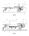
- the Fig. 2a to 2c show the in the Fig. 1a to 1c illustrated agricultural machine in a side view in the same positions.
- Fig. 2a shows, the wheel axle of the main wheels 22a, 22b opposite to the direction of travel to the central frame axis spaced.
- the distance is selected so that the connecting line of the wheel axle with the central frame bearing axis ZA encloses an angle ⁇ with the horizontal. This is preferably in a range of 30 ° to 60 °.
- Such an angle causes a shortening of the wheelbase (distance to the towing vehicle) from the working position to the transport position is made possible by a pivoting of the central frame 14 about the central frame bearing axis ZA by about 90 ° to 95 °.
- Fig. 2b is the transition position in which the work tools 26a, 26b are aligned in vertical position, as already in Fig. 1b described, shown.
- the connecting line of the main wheel axle RA and the central frame bearing axle ZA encloses an angle ⁇ with the horizontal. This is preferably also in a range of 30 ° to 60 °. About this angle, the transport height can be influenced. As compared with Fig. 2a to recognize, corresponds to the distance of the boom wheel 24a from the ground about the supernatant region of the main gear 22a against the direction of travel relative to the boom 24a.
- Fig. 2c finally shows the transport position after pivoting of the boom 16a, 16b about the boom axis AA1, AA2. It is especially good to see Fig. 2c the shortened wheelbase, so the distance between the tractor and the main gear 22a, 22b in the transport position relative to the working position.
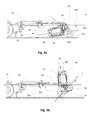
- the Fig. 3a to 3c show an agricultural machine as described above, in which case the working tool is designed as a pickup-Bandschwader 30 or Merger.
- the pickup belt swather 30 comprises a conveyor belt 34 and a Erntegutier choir 32 (pick-up), these functional units are supported by a U-profile frame 36, on which opposite the Erntegutaufsacrificing a rotor 38 is arranged for further promotion of the Erntegutaufexcellent 32 recorded crop ,
- the cantilever bearing axis AA1 extends in this case so that it has a distance from the shaft of Erntegutaufillons, which is smaller than 0.7 times the distance of the horizontal plane in which the centers of the shaft bearings are flat ground to the boom axis AA1 in the lowest point of the boom bearing 20a is. This ensures that upon pivoting of the pick-up-Bandschwaders 30 about the boom axis AA1 a collision of the unit shown with the adjacent (not shown) working units in the middle of the frame can be avoided.
- the orientation of the pick-up Bandschwaders 30 can be influenced in transport position.
- the setting can be selected so that a minimum transport width can be achieved.
- Fig. 3c finally shows the position of the harvester in transport position, with particularly good again the shortening of the wheelbase, the distance of the axis of the main gear 22a to the tractor relative to the working position can be seen.
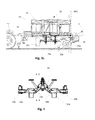
- Fig. 4 shows an agricultural machine according to the invention in rear view. It can be seen particularly well in this illustration that the central frame 14 is designed as a substantially U-shaped profile. At the lower end of the frame, the axes of the main wheels 22a, 22b are arranged. This ensures a particularly large clearance height.
- the cantilever bearings 20a, 20b are arranged between the main wheels 22a, 22b and the drawbar 12. This allows a maximum passage width at a given wheel spacing are made possible, with the wheelbase directed to transport conditions or traffic requirements. Further, the section line AA is shown, at which a band rake according to FIG. 3a is cut.
- Fig. 5 shows a sectional view of a band rake 30 according to the in Fig. 4 illustrated section line AA.
- the design of the central frame 14 can be seen, on which the boom axes AA1, AA2 are arranged inclined.
- the distance D1 from the horizontal wave plane in which the crop pickup shaft lies to the lowest point of the boom bearing axis AA1 in the boom bearing 20a, 20b is greater than the distance D2 of the boom bearing axis AA2 to the shaft axis of the crop pickup.
- D1 preferably corresponds to D1> 1.5 D2.
- the distance D2 from the shaft axis to the boom bearing axis AA1 is greater than the distance of the shaft axis to the ground.
- the belt scraper unit 30 is connected via a link assembly (four-bar linkage) comprising links 40, 42 to the boom arm 16a.
- a link assembly four-bar linkage
- links 40, 42 By means of the link arrangement, a vertical movement can be superimposed by an angular movement about the instantaneous pole M.
- the linkage arrangement is chosen so that the instantaneous pole lies in the working position on a level ground in the direction of travel behind the boom and below the ground level. This ensures a particularly good soil adaptation of Erntegutaufsacrificings in working position.
- Fig. 6 shows a machine according to the invention in the transport position, wherein it can be clearly seen that the belt scraper unit 30 does not exceed the maximum distance predetermined by the main wheels 22a, 22b.
- the belt scraper unit 30 does not exceed the maximum distance predetermined by the main wheels 22a, 22b.
Landscapes
- Life Sciences & Earth Sciences (AREA)
- Environmental Sciences (AREA)
- Engineering & Computer Science (AREA)
- Mechanical Engineering (AREA)
- Soil Sciences (AREA)
- Agricultural Machines (AREA)
Applications Claiming Priority (1)
| Application Number | Priority Date | Filing Date | Title |
|---|---|---|---|
| DE102014110919.8A DE102014110919A1 (de) | 2014-07-31 | 2014-07-31 | Zusammenklappbare landwirtschaftliche Maschine |
Publications (2)
| Publication Number | Publication Date |
|---|---|
| EP2979529A1 true EP2979529A1 (fr) | 2016-02-03 |
| EP2979529B1 EP2979529B1 (fr) | 2018-02-07 |
Family
ID=53773324
Family Applications (1)
| Application Number | Title | Priority Date | Filing Date |
|---|---|---|---|
| EP15179387.4A Active EP2979529B1 (fr) | 2014-07-31 | 2015-07-31 | Machine agricole repliable |
Country Status (2)
| Country | Link |
|---|---|
| EP (1) | EP2979529B1 (fr) |
| DE (1) | DE102014110919A1 (fr) |
Cited By (2)
| Publication number | Priority date | Publication date | Assignee | Title |
|---|---|---|---|---|
| EP3479669A1 (fr) * | 2017-11-03 | 2019-05-08 | Thomas Reiter | Machine agricole |
| US20240147907A1 (en) * | 2022-11-09 | 2024-05-09 | Maschinenfabrik Bernard Krone GmbH & Co. KG | Method for adjusting haymaking machine into transport position |
Families Citing this family (9)
| Publication number | Priority date | Publication date | Assignee | Title |
|---|---|---|---|---|
| DE102019118737A1 (de) | 2019-07-10 | 2021-01-14 | Claas Saulgau Gmbh | Erntevorrichtung |
| DE102019118738A1 (de) | 2019-07-10 | 2021-01-14 | Claas Saulgau Gmbh | Erntevorrichtung und Verfahren zum Überführen derselben zwischen einer Arbeitsstellung und einer Transportstellung |
| DE102019118739A1 (de) | 2019-07-10 | 2021-01-14 | Claas Saulgau Gmbh | Erntevorrichtung |
| DE102020106804A1 (de) | 2020-03-12 | 2021-09-16 | Claas Saulgau Gmbh | Erntevorrichtung |
| DE102020106803A1 (de) | 2020-03-12 | 2021-09-16 | Claas Saulgau Gmbh | Erntevorrichtung |
| DE102020113429A1 (de) | 2020-05-18 | 2021-11-18 | Claas Saulgau Gmbh | Merger-Steuergerät und Merger |
| DE102023114333A1 (de) * | 2023-05-31 | 2024-12-05 | Thomas Reiter | Landwirtschaftliche Maschine |
| DE102024126015A1 (de) * | 2024-09-10 | 2026-03-12 | Claas Saulgau Gmbh | Landwirtschaftliche Erntemaschine |
| DE102024126013A1 (de) | 2024-09-10 | 2026-03-12 | Claas Saulgau Gmbh | Landwirtschaftliche Erntemaschine und Verfahren zum Betreiben derselben |
Citations (6)
| Publication number | Priority date | Publication date | Assignee | Title |
|---|---|---|---|---|
| DE9311671U1 (de) * | 1993-08-05 | 1993-10-07 | H. Niemeyer Söhne GmbH & Co KG, 48477 Hörstel | Heuwerbungsmaschine |
| DE20004538U1 (de) * | 2000-03-10 | 2000-07-06 | Wilhelm Stoll Maschinenfabrik Gmbh, 38268 Lengede | Heuwerbungsmaschine |
| DE10351272A1 (de) * | 2003-10-31 | 2005-06-09 | Claas Saulgau Gmbh | Kreiselschwader |
| US7310929B2 (en) | 2003-03-31 | 2007-12-25 | Oxbo International Corporation | Windrow merging apparatus |
| DE602004009338T2 (de) | 2003-10-29 | 2008-07-17 | Kuhn S.A. | Landmaschine zum schwaden von auf dem boden liegenden produkten |
| US20140069670A1 (en) * | 2012-09-12 | 2014-03-13 | Pillar Lasers Inc. | Rear Folding Tool Bar Implement |
Family Cites Families (2)
| Publication number | Priority date | Publication date | Assignee | Title |
|---|---|---|---|---|
| NL1006945C2 (nl) * | 1997-09-04 | 1999-03-05 | Arend Mulder | Werktuigdrager. |
| DE202006003320U1 (de) * | 2006-03-02 | 2006-04-20 | Fella-Werke Gmbh & Co. Kg | Kreiselschwader |
-
2014
- 2014-07-31 DE DE102014110919.8A patent/DE102014110919A1/de not_active Withdrawn
-
2015
- 2015-07-31 EP EP15179387.4A patent/EP2979529B1/fr active Active
Patent Citations (6)
| Publication number | Priority date | Publication date | Assignee | Title |
|---|---|---|---|---|
| DE9311671U1 (de) * | 1993-08-05 | 1993-10-07 | H. Niemeyer Söhne GmbH & Co KG, 48477 Hörstel | Heuwerbungsmaschine |
| DE20004538U1 (de) * | 2000-03-10 | 2000-07-06 | Wilhelm Stoll Maschinenfabrik Gmbh, 38268 Lengede | Heuwerbungsmaschine |
| US7310929B2 (en) | 2003-03-31 | 2007-12-25 | Oxbo International Corporation | Windrow merging apparatus |
| DE602004009338T2 (de) | 2003-10-29 | 2008-07-17 | Kuhn S.A. | Landmaschine zum schwaden von auf dem boden liegenden produkten |
| DE10351272A1 (de) * | 2003-10-31 | 2005-06-09 | Claas Saulgau Gmbh | Kreiselschwader |
| US20140069670A1 (en) * | 2012-09-12 | 2014-03-13 | Pillar Lasers Inc. | Rear Folding Tool Bar Implement |
Cited By (3)
| Publication number | Priority date | Publication date | Assignee | Title |
|---|---|---|---|---|
| EP3479669A1 (fr) * | 2017-11-03 | 2019-05-08 | Thomas Reiter | Machine agricole |
| US20240147907A1 (en) * | 2022-11-09 | 2024-05-09 | Maschinenfabrik Bernard Krone GmbH & Co. KG | Method for adjusting haymaking machine into transport position |
| EP4367996A1 (fr) * | 2022-11-09 | 2024-05-15 | Maschinenfabrik Bernard Krone GmbH & Co. KG | Procédé de réglage d'une machine de fenaison dans une position de transport |
Also Published As
| Publication number | Publication date |
|---|---|
| DE102014110919A1 (de) | 2016-02-04 |
| EP2979529B1 (fr) | 2018-02-07 |
Similar Documents
| Publication | Publication Date | Title |
|---|---|---|
| EP2979529B1 (fr) | Machine agricole repliable | |
| EP2022316B1 (fr) | Machine de fenaison | |
| EP2529614B1 (fr) | Combinaison de mécanisme de tonte | |
| DE102009017400A1 (de) | Erntemaschine | |
| EP2113396B1 (fr) | Ensemble de roue d'appui pour un ramasseur doté d'un blocage automatique en position de transport | |
| EP1894462B1 (fr) | Convoyeur agricole | |
| DE69104147T2 (de) | Landwirtschaftliche Maschine, insbesondere Schwader für Pflanzengut, mit verstellbarer Arbeitsbreite. | |
| WO2023011683A1 (fr) | Tête de ramassage destinée à une récolteuse-hacheuse de préférence autotractée | |
| EP3556199B1 (fr) | Machine de fenaison agricole | |
| EP1894463B1 (fr) | Moissonneuse agricole dotée d'un dispositif de surcharge | |
| EP3311650B1 (fr) | Machine de fenaison pourvue d'un dispositif d'attelage modulaire | |
| EP3058804B1 (fr) | Faneuse | |
| EP4531538A1 (fr) | Accessoire de ramassage pour machine de récolte | |
| EP2526751B1 (fr) | Faucheuse | |
| DE7215088U (de) | Lagerung der ungelenkten nachlaufraeder von landwirtschaftlichen geraeten insbesondere von an das hubwerk einer zugmaschine anschliessbaren erntemaschinen | |
| DE102006030508B4 (de) | Anordnung zur pendelnden Aufhängung eines Erntevorsatzes an einer Erntemaschine | |
| DE102014208071B4 (de) | Zwischen einer Betriebs- und einer Transportstellung verstellbares landwirtschaftliches Arbeitsgerät | |
| EP3928605B1 (fr) | Appareil adaptable doté d'un dispositif de sécurité, machine agricole dotée de l'appareil adaptable et procédé de transfert de l'appareil adaptable d'un agencement de récolte à un agencement de transport routier | |
| EP3735818B1 (fr) | Engin agricole | |
| EP3616495A1 (fr) | Mécanisme de fixation pour un dispositif de broyage / de coupe pour matière végétale sur un véhicule, en particulier un tracteur ou analogue | |
| EP3732952B1 (fr) | Machine de fenaison | |
| EP2735220B1 (fr) | Tête de récolte mobile entre une position de fonctionnement et une position de transport | |
| EP4706358A1 (fr) | Moissonneuse agricole | |
| EP3087822B1 (fr) | Faneuse | |
| EP4710749A1 (fr) | Agencement d'entraînement pour entraîner une tête de récolte par une récolteuse-hacheuse |
Legal Events
| Date | Code | Title | Description |
|---|---|---|---|
| PUAI | Public reference made under article 153(3) epc to a published international application that has entered the european phase |
Free format text: ORIGINAL CODE: 0009012 |
|
| AK | Designated contracting states |
Kind code of ref document: A1 Designated state(s): AL AT BE BG CH CY CZ DE DK EE ES FI FR GB GR HR HU IE IS IT LI LT LU LV MC MK MT NL NO PL PT RO RS SE SI SK SM TR |
|
| AX | Request for extension of the european patent |
Extension state: BA ME |
|
| 17P | Request for examination filed |
Effective date: 20160803 |
|
| RBV | Designated contracting states (corrected) |
Designated state(s): AL AT BE BG CH CY CZ DE DK EE ES FI FR GB GR HR HU IE IS IT LI LT LU LV MC MK MT NL NO PL PT RO RS SE SI SK SM TR |
|
| GRAP | Despatch of communication of intention to grant a patent |
Free format text: ORIGINAL CODE: EPIDOSNIGR1 |
|
| STAA | Information on the status of an ep patent application or granted ep patent |
Free format text: STATUS: GRANT OF PATENT IS INTENDED |
|
| RIC1 | Information provided on ipc code assigned before grant |
Ipc: A01B 73/06 20060101ALI20170728BHEP Ipc: A01D 84/00 20060101ALI20170728BHEP Ipc: A01B 73/04 20060101AFI20170728BHEP |
|
| INTG | Intention to grant announced |
Effective date: 20170823 |
|
| GRAS | Grant fee paid |
Free format text: ORIGINAL CODE: EPIDOSNIGR3 |
|
| GRAA | (expected) grant |
Free format text: ORIGINAL CODE: 0009210 |
|
| STAA | Information on the status of an ep patent application or granted ep patent |
Free format text: STATUS: THE PATENT HAS BEEN GRANTED |
|
| AK | Designated contracting states |
Kind code of ref document: B1 Designated state(s): AL AT BE BG CH CY CZ DE DK EE ES FI FR GB GR HR HU IE IS IT LI LT LU LV MC MK MT NL NO PL PT RO RS SE SI SK SM TR |
|
| REG | Reference to a national code |
Ref country code: GB Ref legal event code: FG4D Free format text: NOT ENGLISH |
|
| REG | Reference to a national code |
Ref country code: AT Ref legal event code: REF Ref document number: 968421 Country of ref document: AT Kind code of ref document: T Effective date: 20180215 Ref country code: CH Ref legal event code: EP |
|
| REG | Reference to a national code |
Ref country code: IE Ref legal event code: FG4D Free format text: LANGUAGE OF EP DOCUMENT: GERMAN |
|
| REG | Reference to a national code |
Ref country code: DE Ref legal event code: R096 Ref document number: 502015003028 Country of ref document: DE |
|
| REG | Reference to a national code |
Ref country code: NL Ref legal event code: MP Effective date: 20180207 |
|
| REG | Reference to a national code |
Ref country code: FR Ref legal event code: PLFP Year of fee payment: 4 |
|
| PG25 | Lapsed in a contracting state [announced via postgrant information from national office to epo] |
Ref country code: ES Free format text: LAPSE BECAUSE OF FAILURE TO SUBMIT A TRANSLATION OF THE DESCRIPTION OR TO PAY THE FEE WITHIN THE PRESCRIBED TIME-LIMIT Effective date: 20180207 Ref country code: NL Free format text: LAPSE BECAUSE OF FAILURE TO SUBMIT A TRANSLATION OF THE DESCRIPTION OR TO PAY THE FEE WITHIN THE PRESCRIBED TIME-LIMIT Effective date: 20180207 Ref country code: LT Free format text: LAPSE BECAUSE OF FAILURE TO SUBMIT A TRANSLATION OF THE DESCRIPTION OR TO PAY THE FEE WITHIN THE PRESCRIBED TIME-LIMIT Effective date: 20180207 Ref country code: CY Free format text: LAPSE BECAUSE OF FAILURE TO SUBMIT A TRANSLATION OF THE DESCRIPTION OR TO PAY THE FEE WITHIN THE PRESCRIBED TIME-LIMIT Effective date: 20180207 Ref country code: NO Free format text: LAPSE BECAUSE OF FAILURE TO SUBMIT A TRANSLATION OF THE DESCRIPTION OR TO PAY THE FEE WITHIN THE PRESCRIBED TIME-LIMIT Effective date: 20180507 Ref country code: FI Free format text: LAPSE BECAUSE OF FAILURE TO SUBMIT A TRANSLATION OF THE DESCRIPTION OR TO PAY THE FEE WITHIN THE PRESCRIBED TIME-LIMIT Effective date: 20180207 Ref country code: HR Free format text: LAPSE BECAUSE OF FAILURE TO SUBMIT A TRANSLATION OF THE DESCRIPTION OR TO PAY THE FEE WITHIN THE PRESCRIBED TIME-LIMIT Effective date: 20180207 |
|
| PG25 | Lapsed in a contracting state [announced via postgrant information from national office to epo] |
Ref country code: GR Free format text: LAPSE BECAUSE OF FAILURE TO SUBMIT A TRANSLATION OF THE DESCRIPTION OR TO PAY THE FEE WITHIN THE PRESCRIBED TIME-LIMIT Effective date: 20180508 Ref country code: RS Free format text: LAPSE BECAUSE OF FAILURE TO SUBMIT A TRANSLATION OF THE DESCRIPTION OR TO PAY THE FEE WITHIN THE PRESCRIBED TIME-LIMIT Effective date: 20180207 Ref country code: BG Free format text: LAPSE BECAUSE OF FAILURE TO SUBMIT A TRANSLATION OF THE DESCRIPTION OR TO PAY THE FEE WITHIN THE PRESCRIBED TIME-LIMIT Effective date: 20180507 Ref country code: PL Free format text: LAPSE BECAUSE OF FAILURE TO SUBMIT A TRANSLATION OF THE DESCRIPTION OR TO PAY THE FEE WITHIN THE PRESCRIBED TIME-LIMIT Effective date: 20180207 Ref country code: LV Free format text: LAPSE BECAUSE OF FAILURE TO SUBMIT A TRANSLATION OF THE DESCRIPTION OR TO PAY THE FEE WITHIN THE PRESCRIBED TIME-LIMIT Effective date: 20180207 Ref country code: IS Free format text: LAPSE BECAUSE OF FAILURE TO SUBMIT A TRANSLATION OF THE DESCRIPTION OR TO PAY THE FEE WITHIN THE PRESCRIBED TIME-LIMIT Effective date: 20180607 Ref country code: SE Free format text: LAPSE BECAUSE OF FAILURE TO SUBMIT A TRANSLATION OF THE DESCRIPTION OR TO PAY THE FEE WITHIN THE PRESCRIBED TIME-LIMIT Effective date: 20180207 |
|
| PG25 | Lapsed in a contracting state [announced via postgrant information from national office to epo] |
Ref country code: MT Free format text: LAPSE BECAUSE OF FAILURE TO SUBMIT A TRANSLATION OF THE DESCRIPTION OR TO PAY THE FEE WITHIN THE PRESCRIBED TIME-LIMIT Effective date: 20180207 |
|
| PG25 | Lapsed in a contracting state [announced via postgrant information from national office to epo] |
Ref country code: IT Free format text: LAPSE BECAUSE OF FAILURE TO SUBMIT A TRANSLATION OF THE DESCRIPTION OR TO PAY THE FEE WITHIN THE PRESCRIBED TIME-LIMIT Effective date: 20180207 Ref country code: RO Free format text: LAPSE BECAUSE OF FAILURE TO SUBMIT A TRANSLATION OF THE DESCRIPTION OR TO PAY THE FEE WITHIN THE PRESCRIBED TIME-LIMIT Effective date: 20180207 Ref country code: AL Free format text: LAPSE BECAUSE OF FAILURE TO SUBMIT A TRANSLATION OF THE DESCRIPTION OR TO PAY THE FEE WITHIN THE PRESCRIBED TIME-LIMIT Effective date: 20180207 Ref country code: EE Free format text: LAPSE BECAUSE OF FAILURE TO SUBMIT A TRANSLATION OF THE DESCRIPTION OR TO PAY THE FEE WITHIN THE PRESCRIBED TIME-LIMIT Effective date: 20180207 |
|
| REG | Reference to a national code |
Ref country code: DE Ref legal event code: R097 Ref document number: 502015003028 Country of ref document: DE |
|
| PG25 | Lapsed in a contracting state [announced via postgrant information from national office to epo] |
Ref country code: DK Free format text: LAPSE BECAUSE OF FAILURE TO SUBMIT A TRANSLATION OF THE DESCRIPTION OR TO PAY THE FEE WITHIN THE PRESCRIBED TIME-LIMIT Effective date: 20180207 Ref country code: SM Free format text: LAPSE BECAUSE OF FAILURE TO SUBMIT A TRANSLATION OF THE DESCRIPTION OR TO PAY THE FEE WITHIN THE PRESCRIBED TIME-LIMIT Effective date: 20180207 Ref country code: CZ Free format text: LAPSE BECAUSE OF FAILURE TO SUBMIT A TRANSLATION OF THE DESCRIPTION OR TO PAY THE FEE WITHIN THE PRESCRIBED TIME-LIMIT Effective date: 20180207 Ref country code: SK Free format text: LAPSE BECAUSE OF FAILURE TO SUBMIT A TRANSLATION OF THE DESCRIPTION OR TO PAY THE FEE WITHIN THE PRESCRIBED TIME-LIMIT Effective date: 20180207 |
|
| PLBE | No opposition filed within time limit |
Free format text: ORIGINAL CODE: 0009261 |
|
| STAA | Information on the status of an ep patent application or granted ep patent |
Free format text: STATUS: NO OPPOSITION FILED WITHIN TIME LIMIT |
|
| 26N | No opposition filed |
Effective date: 20181108 |
|
| PG25 | Lapsed in a contracting state [announced via postgrant information from national office to epo] |
Ref country code: SI Free format text: LAPSE BECAUSE OF FAILURE TO SUBMIT A TRANSLATION OF THE DESCRIPTION OR TO PAY THE FEE WITHIN THE PRESCRIBED TIME-LIMIT Effective date: 20180207 |
|
| REG | Reference to a national code |
Ref country code: CH Ref legal event code: PL |
|
| PG25 | Lapsed in a contracting state [announced via postgrant information from national office to epo] |
Ref country code: LU Free format text: LAPSE BECAUSE OF NON-PAYMENT OF DUE FEES Effective date: 20180731 Ref country code: MC Free format text: LAPSE BECAUSE OF FAILURE TO SUBMIT A TRANSLATION OF THE DESCRIPTION OR TO PAY THE FEE WITHIN THE PRESCRIBED TIME-LIMIT Effective date: 20180207 |
|
| REG | Reference to a national code |
Ref country code: BE Ref legal event code: MM Effective date: 20180731 |
|
| PG25 | Lapsed in a contracting state [announced via postgrant information from national office to epo] |
Ref country code: LI Free format text: LAPSE BECAUSE OF NON-PAYMENT OF DUE FEES Effective date: 20180731 Ref country code: CH Free format text: LAPSE BECAUSE OF NON-PAYMENT OF DUE FEES Effective date: 20180731 |
|
| REG | Reference to a national code |
Ref country code: IE Ref legal event code: MM4A |
|
| PG25 | Lapsed in a contracting state [announced via postgrant information from national office to epo] |
Ref country code: BE Free format text: LAPSE BECAUSE OF NON-PAYMENT OF DUE FEES Effective date: 20180731 |
|
| PG25 | Lapsed in a contracting state [announced via postgrant information from national office to epo] |
Ref country code: IE Free format text: LAPSE BECAUSE OF NON-PAYMENT OF DUE FEES Effective date: 20180731 |
|
| PG25 | Lapsed in a contracting state [announced via postgrant information from national office to epo] |
Ref country code: TR Free format text: LAPSE BECAUSE OF FAILURE TO SUBMIT A TRANSLATION OF THE DESCRIPTION OR TO PAY THE FEE WITHIN THE PRESCRIBED TIME-LIMIT Effective date: 20180207 |
|
| PG25 | Lapsed in a contracting state [announced via postgrant information from national office to epo] |
Ref country code: PT Free format text: LAPSE BECAUSE OF FAILURE TO SUBMIT A TRANSLATION OF THE DESCRIPTION OR TO PAY THE FEE WITHIN THE PRESCRIBED TIME-LIMIT Effective date: 20180207 |
|
| PG25 | Lapsed in a contracting state [announced via postgrant information from national office to epo] |
Ref country code: HU Free format text: LAPSE BECAUSE OF FAILURE TO SUBMIT A TRANSLATION OF THE DESCRIPTION OR TO PAY THE FEE WITHIN THE PRESCRIBED TIME-LIMIT; INVALID AB INITIO Effective date: 20150731 Ref country code: MK Free format text: LAPSE BECAUSE OF NON-PAYMENT OF DUE FEES Effective date: 20180207 |
|
| PGFP | Annual fee paid to national office [announced via postgrant information from national office to epo] |
Ref country code: GB Payment date: 20200723 Year of fee payment: 6 |
|
| REG | Reference to a national code |
Ref country code: AT Ref legal event code: MM01 Ref document number: 968421 Country of ref document: AT Kind code of ref document: T Effective date: 20200731 |
|
| PG25 | Lapsed in a contracting state [announced via postgrant information from national office to epo] |
Ref country code: AT Free format text: LAPSE BECAUSE OF NON-PAYMENT OF DUE FEES Effective date: 20200731 |
|
| GBPC | Gb: european patent ceased through non-payment of renewal fee |
Effective date: 20210731 |
|
| PG25 | Lapsed in a contracting state [announced via postgrant information from national office to epo] |
Ref country code: GB Free format text: LAPSE BECAUSE OF NON-PAYMENT OF DUE FEES Effective date: 20210731 |
|
| PGFP | Annual fee paid to national office [announced via postgrant information from national office to epo] |
Ref country code: FR Payment date: 20220725 Year of fee payment: 8 |
|
| P01 | Opt-out of the competence of the unified patent court (upc) registered |
Effective date: 20230531 |
|
| PG25 | Lapsed in a contracting state [announced via postgrant information from national office to epo] |
Ref country code: FR Free format text: LAPSE BECAUSE OF NON-PAYMENT OF DUE FEES Effective date: 20230731 |
|
| PGFP | Annual fee paid to national office [announced via postgrant information from national office to epo] |
Ref country code: DE Payment date: 20250729 Year of fee payment: 11 |