EP2979535A2 - Dispositif de coupe pour moissonneuses agricoles - Google Patents
Dispositif de coupe pour moissonneuses agricoles Download PDFInfo
- Publication number
- EP2979535A2 EP2979535A2 EP15002059.2A EP15002059A EP2979535A2 EP 2979535 A2 EP2979535 A2 EP 2979535A2 EP 15002059 A EP15002059 A EP 15002059A EP 2979535 A2 EP2979535 A2 EP 2979535A2
- Authority
- EP
- European Patent Office
- Prior art keywords
- cutting
- cutting device
- blade
- agricultural
- switching
- Prior art date
- Legal status (The legal status is an assumption and is not a legal conclusion. Google has not performed a legal analysis and makes no representation as to the accuracy of the status listed.)
- Granted
Links
Images


Classifications
-
- A—HUMAN NECESSITIES
- A01—AGRICULTURE; FORESTRY; ANIMAL HUSBANDRY; HUNTING; TRAPPING; FISHING
- A01F—PROCESSING OF HARVESTED PRODUCE; HAY OR STRAW PRESSES; DEVICES FOR STORING AGRICULTURAL OR HORTICULTURAL PRODUCE
- A01F29/00—Cutting apparatus specially adapted for cutting hay, straw or the like
- A01F29/09—Details
- A01F29/095—Mounting or adjusting of knives
-
- A—HUMAN NECESSITIES
- A01—AGRICULTURE; FORESTRY; ANIMAL HUSBANDRY; HUNTING; TRAPPING; FISHING
- A01D—HARVESTING; MOWING
- A01D90/00—Vehicles for carrying harvested crops with means for selfloading or unloading
- A01D90/02—Loading means
- A01D90/04—Loading means with additional cutting means
-
- A—HUMAN NECESSITIES
- A01—AGRICULTURE; FORESTRY; ANIMAL HUSBANDRY; HUNTING; TRAPPING; FISHING
- A01F—PROCESSING OF HARVESTED PRODUCE; HAY OR STRAW PRESSES; DEVICES FOR STORING AGRICULTURAL OR HORTICULTURAL PRODUCE
- A01F15/00—Baling presses for straw, hay or the like
- A01F15/08—Details
- A01F15/10—Feeding devices for the crop material e.g. precompression devices
-
- A—HUMAN NECESSITIES
- A01—AGRICULTURE; FORESTRY; ANIMAL HUSBANDRY; HUNTING; TRAPPING; FISHING
- A01F—PROCESSING OF HARVESTED PRODUCE; HAY OR STRAW PRESSES; DEVICES FOR STORING AGRICULTURAL OR HORTICULTURAL PRODUCE
- A01F29/00—Cutting apparatus specially adapted for cutting hay, straw or the like
- A01F29/01—Cutting apparatus specially adapted for cutting hay, straw or the like specially adapted for being mounted on or drawn by a tractor, e.g. field choppers
Definitions
- the invention relates to a cutting device for agricultural harvesters such as forage wagons or balers for harvesting agricultural stalk or leaf material such as grass or hay.
- Such cutting devices are known in practice in various designs and essentially comprise a horizontal Axis driven by rotation and provided with conveyor tines conveying member which cooperates with projecting into a conveyor channel cutting blades to cut the recorded from a receiving device Halm- or sheet material and then supply it to a downstream cargo space.
- balers for the production of round or cuboid crop bales is for installation of such cutting devices only a limited installation space available.
- each knife is supported by a resilient blade lever in the cutting position and thus a rock or the like. Foreign body can dodge automatically.
- the knife levers are mounted approximately at the center of a fixed pin, wherein the knife-facing portion engages with a blade roller attached thereto in a recess on the back of the knife and the other Section is in engagement with cams of a blade lever downstream switching shaft.
- a cam is provided, wherein the cams are mounted so offset from one another on the circumference of the shift shaft that either all, a certain number or none of the blade lever with a cam for adjusting the cutting length of the cutter are engaged.
- This cutting device is particularly associated with the defect that for the actuation of the switching shaft and thus to adjust the cutting length such a large effort required that a direct manual rotation of the stem by an operator is hardly possible. Rather, this expensive transmission gear or the like. Drive means are required.
- a loader wagon in which the projecting into the conveying channel cutting blade via support claws, which are mounted on a switching shaft in individual rows in parallel alignment in different numbers, supported in the cutting position.
- Support edges on the back of the cutting blades are based on forming the formation of a sharp pressure angle on the support jaws of the shift shaft, so that when excessive load on one or more knives by rotation of the stem against the action of overload protection, the support claws from the effective range with the Move out support edges of the cutting blade and thus release a pivoting movement of the cutting blade from the cutting position in a non-cutting position.
- a shortcoming of this cutting device is that when a stone or the like. Foreign body on a cutting blade equal release of all switched cutting blade for a pivoting movement takes place from the cutting position. A protection of individual cutting blades against overload and damage is therefore not possible here.
- the object of the invention is therefore to provide an improved cutting device for agricultural harvesting machines of the aforementioned type, which ensures reliable protection of each individual cutting blade in a compact design, is simple and inexpensive to manufacture and in an adjustment of the cutting length of an operator As little effort as possible is feasible.
- the cutting device of the aforementioned type is characterized by the features stated in the characterizing part of claim 1. With regard to the further embodiment of the invention, reference is made to the other claims.
- a cutting device for agricultural harvesters such as Self loading wagons or balers a cutting device is created by the application of the features according to the invention, in which the operation is greatly facilitated in particular by the smooth, comfortable operation of the preselector for selecting the blade group, which is provided in an engaged and / or disengaged position.
- the cutting device according to the invention provides reliable protection of each individual cutting blade, with the necessary installation space is kept to a minimum and thus occur even in balers and balers in particular for the production of rectangular crop bales no impairment of ground clearance.
- the skillful structural design of the preselecting device of the cutting device according to the invention has managed to provide more than the previously known from the prior art a maximum of 4 switch positions.
- five or six switching positions of the preselector are easily possible.
- more knife groups can be formed in particular in a cutting unit with a high number of blades. Due to this greater possibility of variation when using only a subset of the cutting blade is given a much longer work to re-sharpening the knife.
- the design of the blade switching device with the connected elements for blade actuation and protection must be fundamentally reconsidered.
- the blade switching device is not linearly but pivotally about a pivot axis to perform the switching movement for adjusting the preselected knife in the engaged or disengaged position. Only in this way could a knife switching device be realized in the smallest space, which fulfills the required requirements and also fulfills further functions.
- the advantageous hydraulically driven pivoting movement of the switching device makes complex, wear-resistant shift linkage of known linear drives superfluous.
- the particularly advantageous kinematic design of the clamping unit in conjunction with the pivotable switching device allows all elements of the blade switching device or the clamping device are turned off in an operating position in which all cutting blades are in the inoperative position, have no contact with the preselector. In this operating position, the preselector is free of external influences and resistances by the blade switching device and is therefore very easy to adjust and thus very comfortable to operate for the operator.
- the preselection device is designed as a hexagonal shaft which extends over the entire width of the cutting device and provides cams. Depending on the position, the cams provide the stop for the clamping lever of a knife.
- the configuration of the cams and their rotated position relative to one another on the hexagonal shaft of the preselection device results in the various possible variations of the switchable blade groups. Particularly advantageous this version offers the possibility of a later change of the variations.
- pivotable switching device result from the fact that during pivoting of the switching device in the inoperative position by mechanical contact with the clamping levers, these and thus all other actuating and clamping means are forced out to the inoperative position.
- This advantageous additional function of the switching device increases the reliability especially against gravity or spring-guided versions. Since the area of the cutting device is heavily loaded by the deposition of dirt and crop residues, this often leads to disturbances in the above-mentioned embodiments.
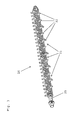
- baler 1 In the Fig. 1 illustrated and movable in the travel and working direction F over a field or meadow surface baler 1 is based on wheels 2, 3 from the ground down and is connected via a drawbar 4 with an agricultural traction and working machine, not shown, the drive of the PTO of the traction and working machine from via a propeller shaft 5 takes place.
- the baler 1 has a receiving device 6, can be canceled by the lying in swaths crops such as straw, hay or wilted green waste from the field or meadow area.
- the receiving device 6 is designed in the illustrated embodiment as a tine 7 equipped with receiving drum 8 known construction, which transverse screw conveyors 9, 10 are assigned to reduce the width of the recorded Erntegutschwades.
- a cutting device 11 which consists essentially of a conveyor and cutting rotor running conveyor 14 with engaging in a conveyor channel 12 feed tines 13, cutting blades 15 and between the cutting blades 15 mounted scrapers 16.
- the crop is promoted by the action of a designed as a computing conveyor conveyor 17 through a feed channel 18 and a Presskanaleinlassö réelle 19 from below into the press channel 20 by a reciprocating plunger 21 compresses the crop into solid cuboid Erntegutballen. Upon reaching a preselected length of Erntegutballen these are incorporated with binding material.
- Knoter learneden 22 with the respective associated binding needles 23 are present.
- the cutting device 11 according to the invention is used on a baler for the production of cuboid Erntegutballen. Equally, however, it is also conceivable to use the cutting device 11 according to the invention on a baling press for the production of round bales or on a self-loading wagon.
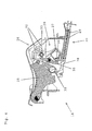
- Fig. 2 is a perspective, enlarged view of the cutting device 11 according to the invention is illustrated in more detail.
- the entire cutting device 11 according to the invention of the embodiment is advantageously constructed on a frame 24, which can be pulled laterally out of this in guided tours of the baler 1 for maintenance purposes.
- Two cutting blades 15, which are shown here for clarity once in the fully pivoted out operating position and once in an intermediate position.
- the other cutting blades 15 of this equipped with many knives cutting device 11 are in the pivoted out of operation.
- the approach of the hexagonal shaft 25 for the operating lever of the preselector 26 is also clearly visible as the Stellzylinder 27 of the blade switching device 28 and the coil springs 29 of the clamping units 30th
- Fig. 3 shows in detail the preselector 26, consisting of pushed onto a hexagonal shaft 25 switching discs 31, which correspond exactly in number and the distance of the cutting blades 15 and thus extend over the entire width of the cutting device 11.
- the switching discs have stop cams 32, which will be discussed later.
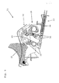
- Fig. 4 shows a side view of a sectional view of the cutting device 11 according to the invention.
- the knife switching device 28 is pivoted about its pivot axis 33 by retracting the adjusting cylinder 27 down, thereby simultaneously the pivot axis 34 of the clamping lever 35 so displaced that the upper free end of the clamping lever 35 outside the effective range (Perimeter diameter) of the stop cam 32 is located.
- the preselector 26 can be easily rotated in one direction, without the forces acting on it by the clamping lever 35, for example, have to be overcome by the coil springs 29 of the clamping units 30.
- the abutment edge 36 of the crossbar 37 of the blade switching device 28 runs against the clamping lever 35 in the region below the pivot axis 34 and thereby forcibly by the connection of the clamping lever 35 with the forks 38 of the clamping units 30, the pivoting back of the lever 39 and thus the descent of the cutting blade 15 in its inactive position.
- FIG. 5 represents an intermediate position during the switching operation of the blade switching device 28 from the inoperative position to the operating position of the cutting device 11.
- the knife switching device 28 is so far around the pivot axis 33rd pivoted counterclockwise, that the clamping lever 35, which is opposed by a stop cam 32 of a switching disc 31 by preselection, come to this plant.
- the pivot axis 34 of the clamping lever 35 also moves further and causes the clamping levers 35, which abut with its upper end to a stop cam 32, a shift of its lower end connected to a fork 38 of a clamping unit 30 end this clamping unit 30 is biased and its associated cutting blade 15 is switched active via the connected lever 39.
- the tensioning levers 35 to which no stop cam 32 is assigned to the preselection device, run out of space during this process underneath the preselection device 26 and thus do not cause pretensioning of a tensioning unit.
- Fig. 6 the end position of the switching operation for activating the preselected cutting blades 15 is shown.
- the selected cutting blades 15 are in the operating position and are held by spring pressure of the corresponding clamping unit 30 via the associated lever 39 there.
- Fig. 6 To recognize the actuating elements 35, 39 of the non-activated cutting blade 15 in its inoperative position. It can be seen advantageously on the cutting device 11 according to the invention that the non-activated clamping units 30 remain completely unloaded in the operating position of the cutting device 11. It also becomes clear how the pivotal movement of the knife switching device 28, which at the same time comprises several functions, has a particularly advantageous effect on the compact design of the cutting device according to the invention.
Landscapes
- Life Sciences & Earth Sciences (AREA)
- Environmental Sciences (AREA)
- Threshing Machine Elements (AREA)
- Harvester Elements (AREA)
- Outside Dividers And Delivering Mechanisms For Harvesters (AREA)
Priority Applications (1)
| Application Number | Priority Date | Filing Date | Title |
|---|---|---|---|
| PL15002059T PL2979535T3 (pl) | 2014-07-30 | 2015-07-09 | Urządzenie tnące do rolniczych maszyn żniwnych |
Applications Claiming Priority (1)
| Application Number | Priority Date | Filing Date | Title |
|---|---|---|---|
| DE202014006083.5U DE202014006083U1 (de) | 2014-07-30 | 2014-07-30 | Schneideinrichtung für landwirtschaftliche Erntemaschinen |
Publications (3)
| Publication Number | Publication Date |
|---|---|
| EP2979535A2 true EP2979535A2 (fr) | 2016-02-03 |
| EP2979535A3 EP2979535A3 (fr) | 2016-02-17 |
| EP2979535B1 EP2979535B1 (fr) | 2018-09-19 |
Family
ID=53719595
Family Applications (1)
| Application Number | Title | Priority Date | Filing Date |
|---|---|---|---|
| EP15002059.2A Active EP2979535B1 (fr) | 2014-07-30 | 2015-07-09 | Dispositif de coupe pour moissonneuses agricoles |
Country Status (5)
| Country | Link |
|---|---|
| US (1) | US9723793B2 (fr) |
| EP (1) | EP2979535B1 (fr) |
| CN (1) | CN105309107B (fr) |
| DE (1) | DE202014006083U1 (fr) |
| PL (1) | PL2979535T3 (fr) |
Cited By (2)
| Publication number | Priority date | Publication date | Assignee | Title |
|---|---|---|---|---|
| EP4282253A1 (fr) * | 2022-05-23 | 2023-11-29 | CNH Industrial Belgium N.V. | Dispositif de coupe de récolte |
| EP4670490A1 (fr) * | 2024-06-28 | 2025-12-31 | CNH Industrial Belgium N.V. | Dispositif de coupe de récolte |
Families Citing this family (18)
| Publication number | Priority date | Publication date | Assignee | Title |
|---|---|---|---|---|
| DE102016120528B4 (de) * | 2016-10-27 | 2019-02-07 | B. Strautmann & Söhne GmbH u. Co. KG | Schneidmesser-Überlastsicherung |
| US10010028B1 (en) * | 2017-07-06 | 2018-07-03 | Cnh Industrial America Llc | Chopper assembly for a harvester with an automatic blade reset mechanism |
| USD860260S1 (en) * | 2017-12-11 | 2019-09-17 | Doppstadt Familienholding Gmbh | Shredder |
| BE1026645B1 (nl) | 2018-09-25 | 2020-04-27 | Cnh Ind Belgium Nv | Gewassnijtoestel, landbouwmachine die zulk gewassnijtoestel bevat en werkwijze om gewas te snijden |
| BE1026646B1 (nl) * | 2018-09-25 | 2020-04-27 | Cnh Ind Belgium Nv | Gewassnijtoestel,landbouwmachine die zulk gewassnijtoestel bevat en werkwijze om het mes te verwijderen |
| DE102019005926A1 (de) | 2019-03-21 | 2020-09-24 | Maschinenfabrik Bernard Krone GmbH & Co. KG | Schneidvorrichtung |
| DE102019005937A1 (de) | 2019-03-21 | 2020-09-24 | Maschinenfabrik Bernard Krone GmbH & Co. KG | Schneidvorrichtung |
| USD918964S1 (en) * | 2019-06-24 | 2021-05-11 | Lig Gmbh | Shredder |
| US11632911B2 (en) * | 2020-02-14 | 2023-04-25 | Cnh Industrial America Llc | Agricultural baler with knife overload mitigating system |
| CN111543192A (zh) * | 2020-04-20 | 2020-08-18 | 鹤岗市田丰农机制造有限公司 | 一种粉碎机粉碎转子 |
| DE102020002580B4 (de) * | 2020-04-29 | 2024-01-25 | Maschinenfabrik Bernard Krone GmbH & Co. KG | Förder- und Sammelvorrichtung mit einer antreibbaren Förder- und Sammeleinheit und landwirtschaftliche Erntegutpresse mit der Förder- und Sammelvorrichtung |
| US11862922B2 (en) | 2020-12-21 | 2024-01-02 | Energetiq Technology, Inc. | Light emitting sealed body and light source device |
| US12414507B2 (en) * | 2021-11-24 | 2025-09-16 | Cnh Industrial America Llc | Knife insert and retract with independent knife protection of agricultural baler |
| US12336453B2 (en) * | 2021-12-29 | 2025-06-24 | Cnh Industrial America Llc | Knife insert and retract with independent knife protection of agricultural baler |
| CA3222908A1 (fr) * | 2022-12-14 | 2024-06-14 | Kuhn-Geldrop B.V. | Dispositif de coupe pour une moissonneuse agricole |
| GB2625328A (en) * | 2022-12-14 | 2024-06-19 | Kuhn Geldrop Bv | Cutter device for an agricultural harvester |
| CN116548187A (zh) * | 2023-06-09 | 2023-08-08 | 胡志诚 | 一种青贮饲料切刀 |
| DE102024106967A1 (de) * | 2024-03-12 | 2025-09-18 | Pöttinger Landtechnik Gmbh | Schneidwerk für eine Erntemaschine |
Citations (3)
| Publication number | Priority date | Publication date | Assignee | Title |
|---|---|---|---|---|
| DE3141414A1 (de) | 1981-10-19 | 1983-05-05 | Klöckner-Humboldt-Deutz AG Zweigniederlassung Fahr, 7702 Gottmadingen | Schneidwerk fuer selbstladeerntewagen |
| DE3213199C1 (de) | 1982-04-08 | 1985-01-31 | Maschinenfabriken Bernard Krone Gmbh, 4441 Spelle | Ladewagen |
| EP2653025A1 (fr) | 2012-04-18 | 2013-10-23 | Usines Claas France S.A.S | Dispositif de coupe pour récolte agricole |
Family Cites Families (18)
| Publication number | Priority date | Publication date | Assignee | Title |
|---|---|---|---|---|
| US2670775A (en) * | 1951-02-12 | 1954-03-02 | Elofson Harry | Stalk and straw disintegrating and scattering device |
| US3005637A (en) * | 1958-09-08 | 1961-10-24 | Polaris Inc | Straw cutters and spreaders |
| DE3474248D1 (en) * | 1984-07-19 | 1988-11-03 | Deere & Co | Chopper device, especially for harvesting machines |
| DE9305838U1 (de) * | 1993-04-20 | 1993-06-17 | Doppstadt, Werner, 5620 Velbert | Zerkleinerungsmaschine mit Nachzerkleinerung für Müll |
| US5368238A (en) * | 1993-10-25 | 1994-11-29 | Deweze Manufacturing, Inc. | Adjustable rotary drum bale cutter apparatus and method |
| US5542883A (en) * | 1995-06-02 | 1996-08-06 | Dutch Industries Ltd. | Straw spreading system |
| DE19640055A1 (de) * | 1996-09-30 | 1998-04-02 | Claas Ohg | Mähdrescher |
| DE19706429C1 (de) * | 1997-02-19 | 1998-04-16 | Fortschritt Erntemaschinen | Schneideinrichtung für landwirtschaftliche Erntemaschinen |
| DE19722793A1 (de) * | 1997-05-30 | 1998-12-03 | Claas Selbstfahr Erntemasch | Mähdrescher |
| DE19832463C2 (de) * | 1998-07-18 | 2002-07-04 | Krone Bernhard Gmbh Maschf | Schneideinrichtung für landwirtschaftliche Erntemaschinen |
| US6298646B1 (en) * | 2000-03-01 | 2001-10-09 | Hay & Forage Industries | Square baler with infeed cutter |
| EP1574124B1 (fr) * | 2004-03-12 | 2007-01-24 | Deere & Company | Appareil de traitement de récolte |
| US6912835B1 (en) * | 2004-06-25 | 2005-07-05 | Deere & Company | Knife selecting arrangement of crop cutting device for use with agricultural machines having a pick-up |
| DE102006036588A1 (de) * | 2006-08-04 | 2008-02-21 | Deere & Company, Moline | Förderkanalwand und landwirtschaftliche Erntemaschine |
| US8146231B2 (en) * | 2007-05-23 | 2012-04-03 | Cnh America Llc | Insertion tool for a rotary chopper element of an integral chopper assembly of a combine harvester |
| DE102008019086A1 (de) | 2008-04-15 | 2009-10-29 | Deere & Company, Moline | Schneidwerk für halmförmiges landwirtschaftliches Erntegut mit einem Mechanismus zur Auswahl der Schnittlänge |
| US7867072B2 (en) * | 2009-03-13 | 2011-01-11 | Cnh America Llc | Rotor tine and rotary element configuration for crop residue treatment systems |
| DE102012007895A1 (de) * | 2012-04-23 | 2013-10-24 | Usines Claas France S.A.S. | Verfahren zur Herstellung einer Schaltwelle |
-
2014
- 2014-07-30 DE DE202014006083.5U patent/DE202014006083U1/de not_active Expired - Lifetime
-
2015
- 2015-07-09 PL PL15002059T patent/PL2979535T3/pl unknown
- 2015-07-09 EP EP15002059.2A patent/EP2979535B1/fr active Active
- 2015-07-28 CN CN201510451408.5A patent/CN105309107B/zh active Active
- 2015-07-29 US US14/811,922 patent/US9723793B2/en active Active
Patent Citations (3)
| Publication number | Priority date | Publication date | Assignee | Title |
|---|---|---|---|---|
| DE3141414A1 (de) | 1981-10-19 | 1983-05-05 | Klöckner-Humboldt-Deutz AG Zweigniederlassung Fahr, 7702 Gottmadingen | Schneidwerk fuer selbstladeerntewagen |
| DE3213199C1 (de) | 1982-04-08 | 1985-01-31 | Maschinenfabriken Bernard Krone Gmbh, 4441 Spelle | Ladewagen |
| EP2653025A1 (fr) | 2012-04-18 | 2013-10-23 | Usines Claas France S.A.S | Dispositif de coupe pour récolte agricole |
Cited By (3)
| Publication number | Priority date | Publication date | Assignee | Title |
|---|---|---|---|---|
| EP4282253A1 (fr) * | 2022-05-23 | 2023-11-29 | CNH Industrial Belgium N.V. | Dispositif de coupe de récolte |
| WO2023227501A1 (fr) * | 2022-05-23 | 2023-11-30 | Cnh Industrial Belgium N.V. | Dispositif de moisson |
| EP4670490A1 (fr) * | 2024-06-28 | 2025-12-31 | CNH Industrial Belgium N.V. | Dispositif de coupe de récolte |
Also Published As
| Publication number | Publication date |
|---|---|
| DE202014006083U1 (de) | 2015-11-04 |
| CN105309107A (zh) | 2016-02-10 |
| US9723793B2 (en) | 2017-08-08 |
| EP2979535B1 (fr) | 2018-09-19 |
| EP2979535A3 (fr) | 2016-02-17 |
| CN105309107B (zh) | 2019-06-07 |
| PL2979535T3 (pl) | 2019-02-28 |
| US20160029567A1 (en) | 2016-02-04 |
Similar Documents
| Publication | Publication Date | Title |
|---|---|---|
| EP2979535B1 (fr) | Dispositif de coupe pour moissonneuses agricoles | |
| EP1121012B1 (fr) | Dispositif de coupe pour moissonneuse agricole | |
| EP2110014B1 (fr) | Dispositif de coupe pour récoltes agricoles en forme de tiges, doté d'un mécanisme destiné à la sélection de la longueur de coupe | |
| EP2653025B1 (fr) | Dispositif de coupe pour récolte agricole | |
| EP0077474B1 (fr) | Dispositif de coupe pour véhicule de récolte autochargeur | |
| DE102013007304B4 (de) | Schneidwerk für eine Erntemaschine | |
| EP2659761B1 (fr) | Moissonneuse dotée d'un dispositif de coupe | |
| DE102014102393A1 (de) | Schneidmesser-Überlastsicherung | |
| EP2742794B1 (fr) | Machine de récolte agricole et procédé de maintenance d'une telle machine de récolte | |
| EP2656725B1 (fr) | Procédé de fabrication d'un arbre de commande | |
| EP0499064B1 (fr) | Machine pour ramasser et presser des produits agricoles récoltés | |
| DE19717542C2 (de) | Schneidvorrichtung für landwirtschaftliche Erntemaschinen | |
| EP3092890B1 (fr) | Barre de coupe de moissonneuse | |
| DE19803835C2 (de) | Aufsammelkolbenpresse | |
| EP4417037B1 (fr) | Dispositif de coupe pour récolte agricole en forme de tige | |
| DE102004023747B4 (de) | Erntemaschine mit einer Aufnahmevorrichtung für landwirtschaftliches Erntegut | |
| EP3721696B1 (fr) | Machine de récolte dotée d'un dispositif de coupe | |
| DE102015008505B4 (de) | Schneidvorrichtung und Erntemaschine | |
| DE10128052A1 (de) | Halterungszusammenbau einer Gutbearbeitungs und/oder Födereinrichtung | |
| DE8130492U1 (de) | Schneidwerk für Selbstladeerntewagen | |
| DE102024103039A1 (de) | Maschine zum Mähen von stängelartigem Erntegut |
Legal Events
| Date | Code | Title | Description |
|---|---|---|---|
| PUAL | Search report despatched |
Free format text: ORIGINAL CODE: 0009013 |
|
| PUAI | Public reference made under article 153(3) epc to a published international application that has entered the european phase |
Free format text: ORIGINAL CODE: 0009012 |
|
| AK | Designated contracting states |
Kind code of ref document: A2 Designated state(s): AL AT BE BG CH CY CZ DE DK EE ES FI FR GB GR HR HU IE IS IT LI LT LU LV MC MK MT NL NO PL PT RO RS SE SI SK SM TR |
|
| AX | Request for extension of the european patent |
Extension state: BA ME |
|
| AK | Designated contracting states |
Kind code of ref document: A3 Designated state(s): AL AT BE BG CH CY CZ DE DK EE ES FI FR GB GR HR HU IE IS IT LI LT LU LV MC MK MT NL NO PL PT RO RS SE SI SK SM TR |
|
| AX | Request for extension of the european patent |
Extension state: BA ME |
|
| RIC1 | Information provided on ipc code assigned before grant |
Ipc: A01F 15/10 20060101ALI20160113BHEP Ipc: A01D 90/04 20060101AFI20160113BHEP |
|
| 17P | Request for examination filed |
Effective date: 20160728 |
|
| RBV | Designated contracting states (corrected) |
Designated state(s): AL AT BE BG CH CY CZ DE DK EE ES FI FR GB GR HR HU IE IS IT LI LT LU LV MC MK MT NL NO PL PT RO RS SE SI SK SM TR |
|
| GRAP | Despatch of communication of intention to grant a patent |
Free format text: ORIGINAL CODE: EPIDOSNIGR1 |
|
| STAA | Information on the status of an ep patent application or granted ep patent |
Free format text: STATUS: GRANT OF PATENT IS INTENDED |
|
| INTG | Intention to grant announced |
Effective date: 20180604 |
|
| GRAS | Grant fee paid |
Free format text: ORIGINAL CODE: EPIDOSNIGR3 |
|
| GRAA | (expected) grant |
Free format text: ORIGINAL CODE: 0009210 |
|
| STAA | Information on the status of an ep patent application or granted ep patent |
Free format text: STATUS: THE PATENT HAS BEEN GRANTED |
|
| AK | Designated contracting states |
Kind code of ref document: B1 Designated state(s): AL AT BE BG CH CY CZ DE DK EE ES FI FR GB GR HR HU IE IS IT LI LT LU LV MC MK MT NL NO PL PT RO RS SE SI SK SM TR |
|
| REG | Reference to a national code |
Ref country code: GB Ref legal event code: FG4D Free format text: NOT ENGLISH |
|
| REG | Reference to a national code |
Ref country code: CH Ref legal event code: EP |
|
| REG | Reference to a national code |
Ref country code: AT Ref legal event code: REF Ref document number: 1042185 Country of ref document: AT Kind code of ref document: T Effective date: 20181015 |
|
| REG | Reference to a national code |
Ref country code: IE Ref legal event code: FG4D Free format text: LANGUAGE OF EP DOCUMENT: GERMAN |
|
| REG | Reference to a national code |
Ref country code: DE Ref legal event code: R096 Ref document number: 502015005912 Country of ref document: DE |
|
| REG | Reference to a national code |
Ref country code: NL Ref legal event code: FP |
|
| PG25 | Lapsed in a contracting state [announced via postgrant information from national office to epo] |
Ref country code: LT Free format text: LAPSE BECAUSE OF FAILURE TO SUBMIT A TRANSLATION OF THE DESCRIPTION OR TO PAY THE FEE WITHIN THE PRESCRIBED TIME-LIMIT Effective date: 20180919 Ref country code: SE Free format text: LAPSE BECAUSE OF FAILURE TO SUBMIT A TRANSLATION OF THE DESCRIPTION OR TO PAY THE FEE WITHIN THE PRESCRIBED TIME-LIMIT Effective date: 20180919 Ref country code: BG Free format text: LAPSE BECAUSE OF FAILURE TO SUBMIT A TRANSLATION OF THE DESCRIPTION OR TO PAY THE FEE WITHIN THE PRESCRIBED TIME-LIMIT Effective date: 20181219 Ref country code: NO Free format text: LAPSE BECAUSE OF FAILURE TO SUBMIT A TRANSLATION OF THE DESCRIPTION OR TO PAY THE FEE WITHIN THE PRESCRIBED TIME-LIMIT Effective date: 20181219 Ref country code: RS Free format text: LAPSE BECAUSE OF FAILURE TO SUBMIT A TRANSLATION OF THE DESCRIPTION OR TO PAY THE FEE WITHIN THE PRESCRIBED TIME-LIMIT Effective date: 20180919 Ref country code: FI Free format text: LAPSE BECAUSE OF FAILURE TO SUBMIT A TRANSLATION OF THE DESCRIPTION OR TO PAY THE FEE WITHIN THE PRESCRIBED TIME-LIMIT Effective date: 20180919 Ref country code: GR Free format text: LAPSE BECAUSE OF FAILURE TO SUBMIT A TRANSLATION OF THE DESCRIPTION OR TO PAY THE FEE WITHIN THE PRESCRIBED TIME-LIMIT Effective date: 20181220 |
|
| REG | Reference to a national code |
Ref country code: LT Ref legal event code: MG4D |
|
| PG25 | Lapsed in a contracting state [announced via postgrant information from national office to epo] |
Ref country code: HR Free format text: LAPSE BECAUSE OF FAILURE TO SUBMIT A TRANSLATION OF THE DESCRIPTION OR TO PAY THE FEE WITHIN THE PRESCRIBED TIME-LIMIT Effective date: 20180919 Ref country code: LV Free format text: LAPSE BECAUSE OF FAILURE TO SUBMIT A TRANSLATION OF THE DESCRIPTION OR TO PAY THE FEE WITHIN THE PRESCRIBED TIME-LIMIT Effective date: 20180919 Ref country code: AL Free format text: LAPSE BECAUSE OF FAILURE TO SUBMIT A TRANSLATION OF THE DESCRIPTION OR TO PAY THE FEE WITHIN THE PRESCRIBED TIME-LIMIT Effective date: 20180919 |
|
| PG25 | Lapsed in a contracting state [announced via postgrant information from national office to epo] |
Ref country code: EE Free format text: LAPSE BECAUSE OF FAILURE TO SUBMIT A TRANSLATION OF THE DESCRIPTION OR TO PAY THE FEE WITHIN THE PRESCRIBED TIME-LIMIT Effective date: 20180919 Ref country code: IT Free format text: LAPSE BECAUSE OF FAILURE TO SUBMIT A TRANSLATION OF THE DESCRIPTION OR TO PAY THE FEE WITHIN THE PRESCRIBED TIME-LIMIT Effective date: 20180919 Ref country code: RO Free format text: LAPSE BECAUSE OF FAILURE TO SUBMIT A TRANSLATION OF THE DESCRIPTION OR TO PAY THE FEE WITHIN THE PRESCRIBED TIME-LIMIT Effective date: 20180919 Ref country code: CZ Free format text: LAPSE BECAUSE OF FAILURE TO SUBMIT A TRANSLATION OF THE DESCRIPTION OR TO PAY THE FEE WITHIN THE PRESCRIBED TIME-LIMIT Effective date: 20180919 Ref country code: IS Free format text: LAPSE BECAUSE OF FAILURE TO SUBMIT A TRANSLATION OF THE DESCRIPTION OR TO PAY THE FEE WITHIN THE PRESCRIBED TIME-LIMIT Effective date: 20190119 Ref country code: ES Free format text: LAPSE BECAUSE OF FAILURE TO SUBMIT A TRANSLATION OF THE DESCRIPTION OR TO PAY THE FEE WITHIN THE PRESCRIBED TIME-LIMIT Effective date: 20180919 |
|
| PG25 | Lapsed in a contracting state [announced via postgrant information from national office to epo] |
Ref country code: SK Free format text: LAPSE BECAUSE OF FAILURE TO SUBMIT A TRANSLATION OF THE DESCRIPTION OR TO PAY THE FEE WITHIN THE PRESCRIBED TIME-LIMIT Effective date: 20180919 Ref country code: PT Free format text: LAPSE BECAUSE OF FAILURE TO SUBMIT A TRANSLATION OF THE DESCRIPTION OR TO PAY THE FEE WITHIN THE PRESCRIBED TIME-LIMIT Effective date: 20190119 Ref country code: SM Free format text: LAPSE BECAUSE OF FAILURE TO SUBMIT A TRANSLATION OF THE DESCRIPTION OR TO PAY THE FEE WITHIN THE PRESCRIBED TIME-LIMIT Effective date: 20180919 |
|
| REG | Reference to a national code |
Ref country code: DE Ref legal event code: R097 Ref document number: 502015005912 Country of ref document: DE |
|
| PLBE | No opposition filed within time limit |
Free format text: ORIGINAL CODE: 0009261 |
|
| STAA | Information on the status of an ep patent application or granted ep patent |
Free format text: STATUS: NO OPPOSITION FILED WITHIN TIME LIMIT |
|
| PG25 | Lapsed in a contracting state [announced via postgrant information from national office to epo] |
Ref country code: DK Free format text: LAPSE BECAUSE OF FAILURE TO SUBMIT A TRANSLATION OF THE DESCRIPTION OR TO PAY THE FEE WITHIN THE PRESCRIBED TIME-LIMIT Effective date: 20180919 |
|
| 26N | No opposition filed |
Effective date: 20190620 |
|
| PG25 | Lapsed in a contracting state [announced via postgrant information from national office to epo] |
Ref country code: SI Free format text: LAPSE BECAUSE OF FAILURE TO SUBMIT A TRANSLATION OF THE DESCRIPTION OR TO PAY THE FEE WITHIN THE PRESCRIBED TIME-LIMIT Effective date: 20180919 |
|
| PG25 | Lapsed in a contracting state [announced via postgrant information from national office to epo] |
Ref country code: MC Free format text: LAPSE BECAUSE OF FAILURE TO SUBMIT A TRANSLATION OF THE DESCRIPTION OR TO PAY THE FEE WITHIN THE PRESCRIBED TIME-LIMIT Effective date: 20180919 |
|
| REG | Reference to a national code |
Ref country code: CH Ref legal event code: PL |
|
| GBPC | Gb: european patent ceased through non-payment of renewal fee |
Effective date: 20190709 |
|
| PG25 | Lapsed in a contracting state [announced via postgrant information from national office to epo] |
Ref country code: TR Free format text: LAPSE BECAUSE OF FAILURE TO SUBMIT A TRANSLATION OF THE DESCRIPTION OR TO PAY THE FEE WITHIN THE PRESCRIBED TIME-LIMIT Effective date: 20180919 |
|
| REG | Reference to a national code |
Ref country code: BE Ref legal event code: MM Effective date: 20190731 |
|
| PG25 | Lapsed in a contracting state [announced via postgrant information from national office to epo] |
Ref country code: GB Free format text: LAPSE BECAUSE OF NON-PAYMENT OF DUE FEES Effective date: 20190709 |
|
| PG25 | Lapsed in a contracting state [announced via postgrant information from national office to epo] |
Ref country code: LU Free format text: LAPSE BECAUSE OF NON-PAYMENT OF DUE FEES Effective date: 20190709 Ref country code: LI Free format text: LAPSE BECAUSE OF NON-PAYMENT OF DUE FEES Effective date: 20190731 Ref country code: CH Free format text: LAPSE BECAUSE OF NON-PAYMENT OF DUE FEES Effective date: 20190731 Ref country code: BE Free format text: LAPSE BECAUSE OF NON-PAYMENT OF DUE FEES Effective date: 20190731 |
|
| PG25 | Lapsed in a contracting state [announced via postgrant information from national office to epo] |
Ref country code: IE Free format text: LAPSE BECAUSE OF NON-PAYMENT OF DUE FEES Effective date: 20190709 |
|
| REG | Reference to a national code |
Ref country code: BE Ref legal event code: NE Effective date: 20210125 |
|
| PG25 | Lapsed in a contracting state [announced via postgrant information from national office to epo] |
Ref country code: CY Free format text: LAPSE BECAUSE OF FAILURE TO SUBMIT A TRANSLATION OF THE DESCRIPTION OR TO PAY THE FEE WITHIN THE PRESCRIBED TIME-LIMIT Effective date: 20180919 |
|
| PG25 | Lapsed in a contracting state [announced via postgrant information from national office to epo] |
Ref country code: HU Free format text: LAPSE BECAUSE OF FAILURE TO SUBMIT A TRANSLATION OF THE DESCRIPTION OR TO PAY THE FEE WITHIN THE PRESCRIBED TIME-LIMIT; INVALID AB INITIO Effective date: 20150709 Ref country code: MT Free format text: LAPSE BECAUSE OF FAILURE TO SUBMIT A TRANSLATION OF THE DESCRIPTION OR TO PAY THE FEE WITHIN THE PRESCRIBED TIME-LIMIT Effective date: 20180919 |
|
| REG | Reference to a national code |
Ref country code: DE Ref legal event code: R081 Ref document number: 502015005912 Country of ref document: DE Owner name: KRONE AGRICULTURE SE, DE Free format text: FORMER OWNER: MASCHINENFABRIK BERNARD KRONE GMBH, 48480 SPELLE, DE |
|
| REG | Reference to a national code |
Ref country code: AT Ref legal event code: MM01 Ref document number: 1042185 Country of ref document: AT Kind code of ref document: T Effective date: 20200709 |
|
| PG25 | Lapsed in a contracting state [announced via postgrant information from national office to epo] |
Ref country code: AT Free format text: LAPSE BECAUSE OF NON-PAYMENT OF DUE FEES Effective date: 20200709 |
|
| REG | Reference to a national code |
Ref country code: NL Ref legal event code: PD Owner name: KRONE AGRICULTURE SE; DE Free format text: DETAILS ASSIGNMENT: CHANGE OF OWNER(S), MERGE; FORMER OWNER NAME: MASCHINENFABRIK KRONE BETEILIGUNGS- GMBH Effective date: 20210909 Ref country code: NL Ref legal event code: HC Owner name: MASCHINENFABRIK KRONE BETEILIGUNGS- GMBH; DE Free format text: DETAILS ASSIGNMENT: CHANGE OF OWNER(S), CHANGE OF OWNER(S) NAME; FORMER OWNER NAME: MASCHINENFABRIK BERNARD KRONE GMBH Effective date: 20210909 |
|
| PG25 | Lapsed in a contracting state [announced via postgrant information from national office to epo] |
Ref country code: MK Free format text: LAPSE BECAUSE OF FAILURE TO SUBMIT A TRANSLATION OF THE DESCRIPTION OR TO PAY THE FEE WITHIN THE PRESCRIBED TIME-LIMIT Effective date: 20180919 |
|
| P01 | Opt-out of the competence of the unified patent court (upc) registered |
Effective date: 20230517 |
|
| PGFP | Annual fee paid to national office [announced via postgrant information from national office to epo] |
Ref country code: PL Payment date: 20250627 Year of fee payment: 11 |
|
| PGFP | Annual fee paid to national office [announced via postgrant information from national office to epo] |
Ref country code: NL Payment date: 20250723 Year of fee payment: 11 |
|
| PGFP | Annual fee paid to national office [announced via postgrant information from national office to epo] |
Ref country code: DE Payment date: 20250722 Year of fee payment: 11 |
|
| PGFP | Annual fee paid to national office [announced via postgrant information from national office to epo] |
Ref country code: FR Payment date: 20250723 Year of fee payment: 11 |