EP2979655A1 - Cathéter d'ablation à ballonnet et système de cathéter d'ablation à ballonnet - Google Patents
Cathéter d'ablation à ballonnet et système de cathéter d'ablation à ballonnet Download PDFInfo
- Publication number
- EP2979655A1 EP2979655A1 EP14775630.8A EP14775630A EP2979655A1 EP 2979655 A1 EP2979655 A1 EP 2979655A1 EP 14775630 A EP14775630 A EP 14775630A EP 2979655 A1 EP2979655 A1 EP 2979655A1
- Authority
- EP
- European Patent Office
- Prior art keywords
- balloon
- ablation catheter
- shaft
- balloon ablation
- catheter
- Prior art date
- Legal status (The legal status is an assumption and is not a legal conclusion. Google has not performed a legal analysis and makes no representation as to the accuracy of the status listed.)
- Granted
Links
Images
Classifications
-
- A—HUMAN NECESSITIES
- A61—MEDICAL OR VETERINARY SCIENCE; HYGIENE
- A61B—DIAGNOSIS; SURGERY; IDENTIFICATION
- A61B18/00—Surgical instruments, devices or methods for transferring non-mechanical forms of energy to or from the body
- A61B18/04—Surgical instruments, devices or methods for transferring non-mechanical forms of energy to or from the body by heating
- A61B18/12—Surgical instruments, devices or methods for transferring non-mechanical forms of energy to or from the body by heating by passing a current through the tissue to be heated, e.g. high-frequency current
- A61B18/14—Probes or electrodes therefor
- A61B18/1492—Probes or electrodes therefor having a flexible, catheter-like structure, e.g. for heart ablation
-
- A—HUMAN NECESSITIES
- A61—MEDICAL OR VETERINARY SCIENCE; HYGIENE
- A61B—DIAGNOSIS; SURGERY; IDENTIFICATION
- A61B18/00—Surgical instruments, devices or methods for transferring non-mechanical forms of energy to or from the body
- A61B2018/00053—Mechanical features of the instrument of device
- A61B2018/0016—Energy applicators arranged in a two- or three dimensional array
-
- A—HUMAN NECESSITIES
- A61—MEDICAL OR VETERINARY SCIENCE; HYGIENE
- A61B—DIAGNOSIS; SURGERY; IDENTIFICATION
- A61B18/00—Surgical instruments, devices or methods for transferring non-mechanical forms of energy to or from the body
- A61B2018/00053—Mechanical features of the instrument of device
- A61B2018/00214—Expandable means emitting energy, e.g. by elements carried thereon
- A61B2018/0022—Balloons
-
- A—HUMAN NECESSITIES
- A61—MEDICAL OR VETERINARY SCIENCE; HYGIENE
- A61B—DIAGNOSIS; SURGERY; IDENTIFICATION
- A61B18/00—Surgical instruments, devices or methods for transferring non-mechanical forms of energy to or from the body
- A61B2018/00053—Mechanical features of the instrument of device
- A61B2018/00273—Anchoring means for temporary attachment of a device to tissue
- A61B2018/00279—Anchoring means for temporary attachment of a device to tissue deployable
- A61B2018/00285—Balloons
-
- A—HUMAN NECESSITIES
- A61—MEDICAL OR VETERINARY SCIENCE; HYGIENE
- A61B—DIAGNOSIS; SURGERY; IDENTIFICATION
- A61B18/00—Surgical instruments, devices or methods for transferring non-mechanical forms of energy to or from the body
- A61B18/04—Surgical instruments, devices or methods for transferring non-mechanical forms of energy to or from the body by heating
- A61B2018/044—Surgical instruments, devices or methods for transferring non-mechanical forms of energy to or from the body by heating the surgical action being effected by a circulating hot fluid
- A61B2018/046—Surgical instruments, devices or methods for transferring non-mechanical forms of energy to or from the body by heating the surgical action being effected by a circulating hot fluid in liquid form
-
- A—HUMAN NECESSITIES
- A61—MEDICAL OR VETERINARY SCIENCE; HYGIENE
- A61B—DIAGNOSIS; SURGERY; IDENTIFICATION
- A61B18/00—Surgical instruments, devices or methods for transferring non-mechanical forms of energy to or from the body
- A61B18/04—Surgical instruments, devices or methods for transferring non-mechanical forms of energy to or from the body by heating
- A61B18/12—Surgical instruments, devices or methods for transferring non-mechanical forms of energy to or from the body by heating by passing a current through the tissue to be heated, e.g. high-frequency current
- A61B18/14—Probes or electrodes therefor
- A61B2018/1472—Probes or electrodes therefor for use with liquid electrolyte, e.g. virtual electrodes
-
- A—HUMAN NECESSITIES
- A61—MEDICAL OR VETERINARY SCIENCE; HYGIENE
- A61M—DEVICES FOR INTRODUCING MEDIA INTO, OR ONTO, THE BODY; DEVICES FOR TRANSDUCING BODY MEDIA OR FOR TAKING MEDIA FROM THE BODY; DEVICES FOR PRODUCING OR ENDING SLEEP OR STUPOR
- A61M25/00—Catheters; Hollow probes
- A61M25/0021—Catheters; Hollow probes characterised by the form of the tubing
- A61M25/0023—Catheters; Hollow probes characterised by the form of the tubing by the form of the lumen, e.g. cross-section, variable diameter
- A61M25/0026—Multi-lumen catheters with stationary elements
-
- A—HUMAN NECESSITIES
- A61—MEDICAL OR VETERINARY SCIENCE; HYGIENE
- A61M—DEVICES FOR INTRODUCING MEDIA INTO, OR ONTO, THE BODY; DEVICES FOR TRANSDUCING BODY MEDIA OR FOR TAKING MEDIA FROM THE BODY; DEVICES FOR PRODUCING OR ENDING SLEEP OR STUPOR
- A61M25/00—Catheters; Hollow probes
- A61M25/0043—Catheters; Hollow probes characterised by structural features
- A61M25/005—Catheters; Hollow probes characterised by structural features with embedded materials for reinforcement, e.g. wires, coils, braids
Definitions
- the present invention relates to a balloon ablation catheter and a balloon ablation catheter system.
- a balloon ablation catheter is a medical device for carrying out ablation by heating a balloon arranged at the catheter tip.
- Patent Document 1 describes a balloon ablation catheter for electric pulmonary vein isolation in treatment of heart arrhythmia.
- This balloon ablation catheter is equipped with means for heating the balloon by allowing high-frequency current to flow between a counter electrode plate attached to the body surface of the patient and an electrode in the balloon. The heated balloon is brought into contact with an affected tissue to carry out treatment of the affected area.
- Patent Document 2 describes a catheter shaft in which a metal wire is installed.
- This catheter shaft has a metal-wire-based reinforcement layer installed on a tube, and the layer improves insertability and torque transmission performance of the body of the tube.
- heating of the balloon ablation catheter causes softening of the catheter shaft affected by the heat, which leads to elongation of the catheter shaft in the longitudinal direction under tensile strength to an extent where the operation by the operator is adversely affected during use of the balloon ablation catheter, which is problematic.
- a possible idea for suppression of the elongation of the catheter shaft in the longitudinal direction due to heating may be installation of a metal wire such as the one descried in Patent Document 2 in the catheter shaft.
- a metal wire such as the one descried in Patent Document 2
- high-frequency current is applied under conditions where the metal wire is installed, high-frequency current is generated in the metal wire in the catheter shaft, and this causes abnormal heating of the metal wire itself, making the operator or tissues other than the affected area in the patient get burned, which is problematic.
- the present invention aims to provide a balloon ablation catheter wherein, even in cases where the catheter shaft is heated by high frequency, elongation of the catheter shaft can be suppressed to an extent where the elongation does not adversely affect use of the balloon ablation catheter, and the risk of a burn of the operator or the patient caused by heating of the reinforcement wire in the catheter shaft can be largely reduced.
- the catheter shaft is not elongated even under the influence of heat due to use of high frequency in combination, and flowing of high frequency through the reinforcement wire can be prevented.
- the balloon ablation catheter of the present invention for ablation of an affected tissue using high frequency is characterized in that it has a catheter shaft containing a reinforcement wire in a thick section, a balloon provided at an end of the catheter shaft, and a high-frequency electric current electrode arranged in the balloon, which balloon ablation catheter satisfies L>t, wherein L represents the shortest distance from the surface of the reinforcement wire to the surface of the catheter shaft, and t represents the wall thickness of the thinnest portion of the balloon.
- the "thick section” herein means the area surrounded by the outer surface of the catheter shaft excluding the area of the lumen portion, and corresponds to the thickness of the catheter shaft.
- the "reinforcement wire” means a wire installed in the catheter shaft for reinforcement of the rigidity of the catheter shaft.
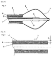
- Fig. 1 is a longitudinal cross-sectional view of the tip section of a balloon ablation catheter according to the first mode of the present invention.
- the balloon ablation catheter 1 has a double tube shaft 9 having an outer cylinder shaft 3 and an inner cylinder shaft 6; and a balloon 2.
- the balloon 2 has a spherical shape, and the outer cylinder shaft 6, which is a flexible tube, is connected to the balloon 2 such that the tip of the outer cylinder shaft 6 is connected to the opening in the base-end side of the balloon 2.
- the inner cylinder shaft 6, which is a flexible tube passes through the inside of the balloon 2, and is connected to the opening in the tip side of the balloon 2. By this, the balloon 2 is tightly sealed.
- An electrode 5 is placed on the inner cylinder shaft 6 in the balloon 2, and the electrode 5 is connected to a high-frequency power source not shown in the figure through an electric wire 7.
- an electric wire 8 for a temperature sensor is connected to the electrode 5, and the electrode 5 also plays a role as a temperature sensor.
- the electrode 5 is arranged near the longitudinal center of the balloon so that the temperature in the balloon 2 can be measured.
- Fig. 2 is a schematic diagram showing a longitudinal cross-sectional view of the outer cylinder shaft contained in the balloon ablation catheter according to the first mode of the present invention.
- the thick section of the outer cylinder shaft 3 in Fig. 1 is constituted by a portion having a thickness with a three-layer structure from the surface of the lumen of an inner layer tube 9 to the surface of the outer layer of an outer layer tube 10, wherein a reinforcement wire 4 is sandwiched therebetween.
- the distance L represents the distance from the outermost surface in the outer layer side of the reinforcement layer 4 to the surface of the outer layer tube 10.
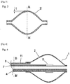
- Fig. 3 is a schematic diagram showing a longitudinal cross-sectional view of the balloon contained in the balloon ablation catheter according to the first mode of the present invention.
- the wall thickness of the thinnest portion in the balloon 2 is defined as the wall thickness t.
- the wall thickness on the A-A' plane, where the diameter of the balloon in the direction vertical to the longitudinal direction is largest, is the wall thickness t.
- the reinforcement wire 4 is arranged such that L is larger than the wall thickness t.
- the material of the balloon 2 may be any material as long as the material is one which is used for medical catheters. From the viewpoint of achievement of increased adhesion to the affected tissue, the material is preferably an elastic material such as a polyurethane or a rubber, for example, a synthetic rubber or a natural rubber.
- the wall thickness of the balloon 2 is preferably 20 to 150 ⁇ m, more preferably 20 to 100 ⁇ m, from the viewpoint of achievement of better adhesion to the affected tissue.
- the outer diameter of the balloon 2 varies depending on the affected area to which the operational technique is applied. For example, in cases of treatment of arrhythmia, the outer diameter is preferably 20 to 40 mm.
- the balloon 2 preferably has a spherical shape, but may also have a tapered conical shape. The shape of the balloon 2 is not limited to these.
- the material of the outer cylinder shaft 3 and the inner cylinder shaft 6 may be any material as long as the material is one which is used for medical catheters.
- the material include polymer materials having flexibility, such as polyamide resins and polyamide elastomers including nylon 11 and nylon 12; polyolefins including polypropylene/polyethylene; polyesters including polyethylene terephthalate; polyurethane; and vinyl chloride. One of these, or a combination of two or more of these may be used.
- an imaging substance such as barium sulfate or bismuth subcarbonate may be included in the material of the outer cylinder shaft 3 and the inner cylinder shaft 6.
- the catheter shaft has a double-tube structure composed of an outer cylinder shaft and an inner cylinder shaft.
- the catheter shaft may also be in a multi-lumen shape.
- Fig. 4 is a longitudinal cross-sectional view of a balloon ablation catheter according to the second mode of the present invention.
- a multi-lumen shaft 11 is used instead of the shaft having a double-tube structure.
- the reinforcement wire 4 is linearly installed along the longitudinal direction of the multi-lumen shaft 11 in the thick section of the multi-lumen shaft 12.
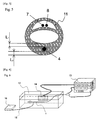
- Fig. 5 is a cross-sectional view of the multi-lumen shaft 12 shown in Fig. 4 taken on the B-B' plane, which is in the direction vertical to the longitudinal direction of the shaft.
- the thick section corresponds to the thickness from an inner cavity, lumen, to the surface of the outer layer of the shaft, wherein the reinforcement wire 4 is sandwiched therebetween.
- the distance L can be interpreted in two ways-that is, L 1 , the shortest distance from the surface of the reinforcement wire 4 to the surface of the lumen of the multi-lumen shaft 12, and L 2 , the shortest distance from the surface of the reinforcement wire 4 to the outer surface of the multi-lumen shaft 12. In cases where the shorter distance selected from L 1 and L 2 is longer than the wall thickness of the balloon 2, t, heating of the reinforcement wire 4 can be prevented.
- the material of the reinforcement wire 4 may be an aramid yarn or a nylon yarn, a carbon fiber, or a metal wire.
- a metal wire of SUS, NiTi alloy, or platinum is preferably used.
- the reinforcement wire is preferably arranged such that the reinforcement wire is not exposed from the distal end tip of the catheter shaft.
- the cross-sectional shape of the reinforcement wire 4 is not limited. In cases where the wire has a rectangular cross section, when the reinforcement wire 4 is installed to form a braid, the friction increases due to an increase in the contacting area among reinforcement wires 4, so that elongation of the catheter shaft can be better reduced.
- the material of the electrode 5 and the electric wire 7 may be any metal as long as the metal allows electric transmission.
- a highly conductive electric wire of copper, silver, gold, platinum, tungsten, an alloy, or the like is preferably used.
- the metal for the electric wire 8 for a temperature sensor needs to be different from that of the electric wire 7.
- the electric wire 7 is a copper wire
- the electric wire 8 for a temperature sensor is a constantan wire.
- the electric wires are not limited to these.
- the electric wire 7 plays roles both as an electric wire for transmitting high-frequency current and as an electric wire for formation of a thermocouple.
- the electric wire for transmitting high-frequency current and the electric wire for a thermocouple may be separately provided.
- a balloon 2 was provided as a spherical balloon wherein the wall thickness at the thinnest portion is 40 ⁇ m; the outer balloon diameter is 25 mm; the neck portion at the base-end section of the balloon has a longitudinal length of 10 mm, an outer diameter of 3.6 mm, and an inner diameter of 3.1 mm; and the neck portion at the tip section of the balloon has a longitudinal length of 10 mm, an outer diameter of 2 mm, and an inner diameter of 1.6 mm.
- the balloon 2 was prepared by blow molding using a urethane material.
- an SUS plate reinforcement wire 4 having a thickness of 60 ⁇ m and a width of 190 ⁇ m was arranged in a mesh-like shape along the longitudinal direction of the inner layer tube 9.
- the reinforcement wire was further covered with a polyurethane material such that the outer diameter was 3.1 mm to form an outer layer tube 10, thereby preparing an outer cylinder shaft 3 having a three-layer structure.
- the outer cylinder shaft 3 was provided as a single-lumen catheter shaft having an inner diameter of 2.5 mm, an outer diameter of 3.1 mm, a thickness of 300 ⁇ m, and a length of 900 mm, wherein the shortest distance from the surface of the reinforcement wire 4 to the surface of the outer cylinder shaft 3 is 130 ⁇ m.
- the inner cylinder shaft 6 was prepared using nylon as a material such that a single-lumen shaft having an inner diameter of 1.2 mm and an outer diameter of 1.6mm was provided.
- As the electrode 5 a copper wire subjected to silver plating having a wire diameter of 30 ⁇ m was used, and the wire was wound around the inner cylinder shaft 6 into a coil shape from the position 20 mm distant from the tip of the inner cylinder shaft 6 toward the base end in the longitudinal direction along a distance of 10 mm.
- a constantan electric wire 8 with a wire diameter of 25 ⁇ m for a temperature sensor was folded together to form a thermocouple.
- the coil end of the electrode 5 was linearly extended in the longitudinal direction toward the base end of the inner cylinder shaft 6 in order to use the copper wire also as the electric wire 7.
- the inner cylinder shaft assembly prepared as described above by combining the inner cylinder shaft 6 with the electrode 5, the electric wire 7, and the electric wire 8 for a temperature sensor was inserted into the outer cylinder shaft 3 such that the assembly protrudes 35 mm from the outer cylinder shaft 3 toward the tip side in the longitudinal direction.
- the neck portion in the base-end side in the longitudinal direction of the balloon 2 was adhered to the outer cylinder shaft 3 under heat, and the neck portion in the tip side in the longitudinal direction of the balloon 2 was adhered to the inner cylinder shaft 6 under heat, to prepare a balloon ablation catheter 1.
- an ablation catheter was prepared such that the catheter has the same constitution as that of Preparation Example 1 except that the reinforcement wire 4 was not installed in the outer cylinder shaft 3, and that a single-lumen catheter shaft was prepared using a polyurethane member tube having an inner diameter of 2.5 mm, an outer diameter of 3.1 mm, and a length of 900 mm.
- an outer cylinder shaft 3 was prepared as follows. Tubing was carried out with a polyurethane member such that the inner diameter was 2.5 mm and the thickness was 180 ⁇ m, and an SUS reinforcement wire 4 having a wire diameter of 40 ⁇ m was linearly arranged thereon along the longitudinal direction, followed by carrying out tubing thereon with the same polyurethane member such that the outer diameter was 3.0 mm, to prepare the outer cylinder shaft.
- the obtained outer cylinder shaft 3 had an inner diameter of 2.5 mm, an outer diameter of 3.0 mm, a thickness of 250 ⁇ m, and a length of 900 mm.
- Other constitutions were the same as those of Preparation Example 1.
- Example 1 The balloon ablation catheters prepared in Example 1 and Comparative Example 1 were immersed in warm water at 37°C for 2 hours. Subsequently, while the tip in the longitudinal direction of the outer cylinder shaft of each catheter was held with a hand, weight was applied by giving a 7-kg weight to the posterior end in the longitudinal direction of the outer cylinder shaft for a sufficient time. Thereafter, elongation of the outer cylinder shaft was compared.
- the outer cylinder shaft of the balloon ablation catheter of Preparation Example 1 elongated from 900 mm to 901 mm, and the outer cylinder shaft 3 did not cover the electrode 5.
- the outer cylinder shaft of the balloon ablation catheter of Comparative Example 1 elongated from 900 mm to 910 mm, and the outer cylinder shaft 3 covered most part of the electrode 5.
- use of the balloon ablation catheter became difficult in this case.
- Example 1 For comparison of the heat generating property between Example 1 and Comparative Example 2, high-frequency power was supplied to the balloon ablation catheters prepared in Example 1 and Comparative Example 2, and the surface temperature of the catheter shaft was compared between these.
- Fig. 6 shows a schematic view of a catheter shaft heat generation test system.
- thermocouple 15 On the surface of the outer cylinder shaft 3 in the vicinity of the balloon of the balloon ablation catheter 1, a thermocouple 15 was attached, and the temperature during application of high-frequency current was measured by a temperature measuring device 16.
- Example 1 and Comparative Example 2 were inflated to an outer diameter of 25 mm by injection of 50% dilution of a contrast medium (ioxaglate injection; trade name, Hexabrix 320) in physiological saline into the balloons 2.
- a contrast medium ioxaglate injection; trade name, Hexabrix 320
- thermocouple was placed at the position 15 mm distant from the tip of the outer cylinder shaft 3.
- the frequency of the high-frequency power source was set to 1.8 Mhz, and the temperature in the balloon 2 was set to 70°C.
- the measured surface temperature of the outer cylinder shaft 3 was 39°C in Example 1.
- the measured surface temperature of the outer cylinder shaft 3 was 51 °C.
- the balloon ablation catheter of the present invention prevents generation of heat from the outer cylinder shaft.
- the present invention can be used as a balloon ablation catheter and as a balloon ablation catheter system for ablation of an affected target area.
Landscapes
- Health & Medical Sciences (AREA)
- Life Sciences & Earth Sciences (AREA)
- Engineering & Computer Science (AREA)
- Surgery (AREA)
- Heart & Thoracic Surgery (AREA)
- Veterinary Medicine (AREA)
- Public Health (AREA)
- General Health & Medical Sciences (AREA)
- Animal Behavior & Ethology (AREA)
- Biomedical Technology (AREA)
- Molecular Biology (AREA)
- Otolaryngology (AREA)
- Nuclear Medicine, Radiotherapy & Molecular Imaging (AREA)
- Plasma & Fusion (AREA)
- Physics & Mathematics (AREA)
- Cardiology (AREA)
- Medical Informatics (AREA)
- Surgical Instruments (AREA)
- Media Introduction/Drainage Providing Device (AREA)
- Biophysics (AREA)
- Hematology (AREA)
- Anesthesiology (AREA)
- Pulmonology (AREA)
- Electrotherapy Devices (AREA)
Applications Claiming Priority (2)
| Application Number | Priority Date | Filing Date | Title |
|---|---|---|---|
| JP2013068479 | 2013-03-28 | ||
| PCT/JP2014/059181 WO2014157633A1 (fr) | 2013-03-28 | 2014-03-28 | Cathéter d'ablation à ballonnet et système de cathéter d'ablation à ballonnet |
Publications (3)
| Publication Number | Publication Date |
|---|---|
| EP2979655A1 true EP2979655A1 (fr) | 2016-02-03 |
| EP2979655A4 EP2979655A4 (fr) | 2016-11-09 |
| EP2979655B1 EP2979655B1 (fr) | 2018-11-07 |
Family
ID=51624589
Family Applications (1)
| Application Number | Title | Priority Date | Filing Date |
|---|---|---|---|
| EP14775630.8A Active EP2979655B1 (fr) | 2013-03-28 | 2014-03-28 | Cathéter d'ablation à ballonnet et système de cathéter d'ablation à ballonnet |
Country Status (10)
| Country | Link |
|---|---|
| US (1) | US11172983B2 (fr) |
| EP (1) | EP2979655B1 (fr) |
| JP (1) | JP6287833B2 (fr) |
| KR (1) | KR102178429B1 (fr) |
| CN (1) | CN105050520B (fr) |
| CA (1) | CA2901243C (fr) |
| DK (1) | DK2979655T3 (fr) |
| ES (1) | ES2698616T3 (fr) |
| TW (1) | TWI598071B (fr) |
| WO (1) | WO2014157633A1 (fr) |
Families Citing this family (10)
| Publication number | Priority date | Publication date | Assignee | Title |
|---|---|---|---|---|
| EP3397149A4 (fr) | 2015-12-30 | 2019-08-14 | Schuler Scientific Solutions, LLC | Cartographie et traitement de tissu |
| US12514632B2 (en) | 2015-12-30 | 2026-01-06 | Biozonal Id, Llc | Tissue mapping and treatment |
| WO2017146465A1 (fr) * | 2016-02-22 | 2017-08-31 | 재단법인 아산사회복지재단 | Procédé de fabrication d'extrémité avant de cathéter de cautérisation par placage électrolytique |
| CN116018101A (zh) * | 2020-08-31 | 2023-04-25 | 波士顿科学医学有限公司 | 可扩张电穿孔装置及其使用方法 |
| WO2022077313A1 (fr) * | 2020-10-15 | 2022-04-21 | 山前(珠海)医疗科技有限公司 | Cathéter à cryoballonnet doté d'une fonction de chauffage |
| US11484327B2 (en) * | 2021-02-26 | 2022-11-01 | Fastwave Medical Inc. | Intravascular lithotripsy |
| US11911056B2 (en) | 2021-02-26 | 2024-02-27 | Fastwave Medical Inc. | Intravascular lithotripsy |
| US11944331B2 (en) | 2021-02-26 | 2024-04-02 | Fastwave Medical Inc. | Intravascular lithotripsy |
| AU2023280407A1 (en) | 2022-06-01 | 2024-11-07 | Fastwave Medical Inc. | Intravascular lithotripsy |
| US12193738B2 (en) | 2022-06-01 | 2025-01-14 | Fastwave Medical Inc. | Intravascular lithotripsy |
Family Cites Families (15)
| Publication number | Priority date | Publication date | Assignee | Title |
|---|---|---|---|---|
| US5807395A (en) * | 1993-08-27 | 1998-09-15 | Medtronic, Inc. | Method and apparatus for RF ablation and hyperthermia |
| US6053913A (en) * | 1998-09-10 | 2000-04-25 | Tu; Lily Chen | Rapid exchange stented balloon catheter having ablation capabilities |
| JP2000225195A (ja) | 1999-02-05 | 2000-08-15 | Hitachi Cable Ltd | カテーテルチューブおよびその製造方法 |
| JP2002078809A (ja) | 2000-09-07 | 2002-03-19 | Shutaro Satake | 肺静脈電気的隔離用バルーンカテーテル |
| CN2462972Y (zh) * | 2001-02-16 | 2001-12-05 | 重庆医科大学 | 循环式水囊超声消融导管 |
| TWI235073B (en) * | 2002-08-20 | 2005-07-01 | Toray Industries | Catheter for treating cardiac arrhythmias |
| EP1585574A4 (fr) * | 2002-12-20 | 2006-04-26 | Cardiac Inv S Unltd Inc | Appareil et procede d'implantation d'electrodes de stimulation ventriculaire dans le sinus coronaire |
| JP4067976B2 (ja) * | 2003-01-24 | 2008-03-26 | 有限会社日本エレクテル | 高周波加温バルーンカテーテル |
| US8185194B2 (en) * | 2003-02-21 | 2012-05-22 | Dtherapeutics, Llc | Systems and methods for determining phasic cardiac cycle measurements |
| JP4140483B2 (ja) * | 2003-08-13 | 2008-08-27 | 東レ株式会社 | バルーン付きアブレーションカテーテル |
| DE202004021946U1 (de) * | 2003-09-12 | 2013-05-29 | Vessix Vascular, Inc. | Auswählbare exzentrische Remodellierung und/oder Ablation von atherosklerotischem Material |
| WO2007052341A1 (fr) * | 2005-11-01 | 2007-05-10 | Japan Electel Inc. | Systeme de catheter a ballonnet |
| US9717501B2 (en) * | 2007-11-21 | 2017-08-01 | St. Jude Medical, Atrial Fibrillation Division, Inc. | Methods and systems for occluding vessels during cardiac ablation including optional electroanatomical guidance |
| TWI517833B (zh) * | 2009-03-31 | 2016-01-21 | 東麗股份有限公司 | 附有氣球之電燒導管用軸及附有氣球之電燒導管系統 |
| US20120150107A1 (en) * | 2010-12-14 | 2012-06-14 | Boston Scientific Scimed, Inc. | Balloon catheter shafts and methods of manufacturing |
-
2014
- 2014-03-20 TW TW103110423A patent/TWI598071B/zh active
- 2014-03-28 JP JP2014514956A patent/JP6287833B2/ja active Active
- 2014-03-28 EP EP14775630.8A patent/EP2979655B1/fr active Active
- 2014-03-28 ES ES14775630T patent/ES2698616T3/es active Active
- 2014-03-28 US US14/777,634 patent/US11172983B2/en active Active
- 2014-03-28 WO PCT/JP2014/059181 patent/WO2014157633A1/fr not_active Ceased
- 2014-03-28 CA CA2901243A patent/CA2901243C/fr active Active
- 2014-03-28 KR KR1020157024967A patent/KR102178429B1/ko not_active Expired - Fee Related
- 2014-03-28 CN CN201480018200.8A patent/CN105050520B/zh active Active
- 2014-03-28 DK DK14775630.8T patent/DK2979655T3/en active
Also Published As
| Publication number | Publication date |
|---|---|
| JP6287833B2 (ja) | 2018-03-07 |
| US11172983B2 (en) | 2021-11-16 |
| US20160287323A1 (en) | 2016-10-06 |
| DK2979655T3 (en) | 2019-03-04 |
| KR20150135264A (ko) | 2015-12-02 |
| JPWO2014157633A1 (ja) | 2017-02-16 |
| CN105050520A (zh) | 2015-11-11 |
| CA2901243C (fr) | 2018-02-06 |
| ES2698616T3 (es) | 2019-02-05 |
| KR102178429B1 (ko) | 2020-11-13 |
| WO2014157633A1 (fr) | 2014-10-02 |
| CA2901243A1 (fr) | 2014-10-02 |
| CN105050520B (zh) | 2017-06-27 |
| TWI598071B (zh) | 2017-09-11 |
| EP2979655B1 (fr) | 2018-11-07 |
| TW201446213A (zh) | 2014-12-16 |
| EP2979655A4 (fr) | 2016-11-09 |
Similar Documents
| Publication | Publication Date | Title |
|---|---|---|
| EP2979655B1 (fr) | Cathéter d'ablation à ballonnet et système de cathéter d'ablation à ballonnet | |
| CN102917660B (zh) | 电位测定用导管 | |
| EP2073738B1 (fr) | Cathéter d'ablation à une ou plusieurs électrodes | |
| US8540662B2 (en) | Medical devices having an atraumatic distal tip segment | |
| JP2012254140A (ja) | バルーン付きアブレーションカテーテル | |
| JP2002360702A (ja) | カテーテルの製造方法およびそのカテーテル | |
| CN102008301B (zh) | 多腔电生理电极导管 | |
| US8082042B2 (en) | Electrode device for electrodiagnosis and/or electrotherapy | |
| JPWO2020188823A1 (ja) | カテーテル | |
| CN114025820B (zh) | 导管及其制造方法 | |
| JP7674700B2 (ja) | 体組織穿孔用デバイス | |
| US20220304748A1 (en) | Catheter device, catheter body, and catheter | |
| JP2025006086A (ja) | 電極カテーテル | |
| JP4140483B2 (ja) | バルーン付きアブレーションカテーテル | |
| US20230038069A1 (en) | Balloon-type electrode catheter | |
| JP7701213B2 (ja) | 電極カテーテル | |
| US20220304625A1 (en) | Catheter device and catheter |
Legal Events
| Date | Code | Title | Description |
|---|---|---|---|
| PUAI | Public reference made under article 153(3) epc to a published international application that has entered the european phase |
Free format text: ORIGINAL CODE: 0009012 |
|
| 17P | Request for examination filed |
Effective date: 20150813 |
|
| AK | Designated contracting states |
Kind code of ref document: A1 Designated state(s): AL AT BE BG CH CY CZ DE DK EE ES FI FR GB GR HR HU IE IS IT LI LT LU LV MC MK MT NL NO PL PT RO RS SE SI SK SM TR |
|
| AX | Request for extension of the european patent |
Extension state: BA ME |
|
| DAX | Request for extension of the european patent (deleted) | ||
| A4 | Supplementary search report drawn up and despatched |
Effective date: 20161010 |
|
| RIC1 | Information provided on ipc code assigned before grant |
Ipc: A61B 18/04 20060101AFI20160930BHEP Ipc: A61M 25/10 20060101ALI20160930BHEP Ipc: A61B 18/14 20060101ALI20160930BHEP |
|
| STAA | Information on the status of an ep patent application or granted ep patent |
Free format text: STATUS: EXAMINATION IS IN PROGRESS |
|
| 17Q | First examination report despatched |
Effective date: 20170424 |
|
| GRAP | Despatch of communication of intention to grant a patent |
Free format text: ORIGINAL CODE: EPIDOSNIGR1 |
|
| STAA | Information on the status of an ep patent application or granted ep patent |
Free format text: STATUS: GRANT OF PATENT IS INTENDED |
|
| INTG | Intention to grant announced |
Effective date: 20180606 |
|
| GRAS | Grant fee paid |
Free format text: ORIGINAL CODE: EPIDOSNIGR3 |
|
| GRAA | (expected) grant |
Free format text: ORIGINAL CODE: 0009210 |
|
| STAA | Information on the status of an ep patent application or granted ep patent |
Free format text: STATUS: THE PATENT HAS BEEN GRANTED |
|
| AK | Designated contracting states |
Kind code of ref document: B1 Designated state(s): AL AT BE BG CH CY CZ DE DK EE ES FI FR GB GR HR HU IE IS IT LI LT LU LV MC MK MT NL NO PL PT RO RS SE SI SK SM TR |
|
| REG | Reference to a national code |
Ref country code: GB Ref legal event code: FG4D |
|
| REG | Reference to a national code |
Ref country code: CH Ref legal event code: EP Ref country code: AT Ref legal event code: REF Ref document number: 1061165 Country of ref document: AT Kind code of ref document: T Effective date: 20181115 |
|
| REG | Reference to a national code |
Ref country code: NL Ref legal event code: FP |
|
| REG | Reference to a national code |
Ref country code: DE Ref legal event code: R096 Ref document number: 602014035621 Country of ref document: DE |
|
| REG | Reference to a national code |
Ref country code: IE Ref legal event code: FG4D |
|
| REG | Reference to a national code |
Ref country code: SE Ref legal event code: TRGR |
|
| REG | Reference to a national code |
Ref country code: ES Ref legal event code: FG2A Ref document number: 2698616 Country of ref document: ES Kind code of ref document: T3 Effective date: 20190205 |
|
| REG | Reference to a national code |
Ref country code: DK Ref legal event code: T3 Effective date: 20190225 |
|
| REG | Reference to a national code |
Ref country code: LT Ref legal event code: MG4D |
|
| REG | Reference to a national code |
Ref country code: AT Ref legal event code: MK05 Ref document number: 1061165 Country of ref document: AT Kind code of ref document: T Effective date: 20181107 |
|
| PG25 | Lapsed in a contracting state [announced via postgrant information from national office to epo] |
Ref country code: IS Free format text: LAPSE BECAUSE OF FAILURE TO SUBMIT A TRANSLATION OF THE DESCRIPTION OR TO PAY THE FEE WITHIN THE PRESCRIBED TIME-LIMIT Effective date: 20190307 Ref country code: BG Free format text: LAPSE BECAUSE OF FAILURE TO SUBMIT A TRANSLATION OF THE DESCRIPTION OR TO PAY THE FEE WITHIN THE PRESCRIBED TIME-LIMIT Effective date: 20190207 Ref country code: LT Free format text: LAPSE BECAUSE OF FAILURE TO SUBMIT A TRANSLATION OF THE DESCRIPTION OR TO PAY THE FEE WITHIN THE PRESCRIBED TIME-LIMIT Effective date: 20181107 Ref country code: HR Free format text: LAPSE BECAUSE OF FAILURE TO SUBMIT A TRANSLATION OF THE DESCRIPTION OR TO PAY THE FEE WITHIN THE PRESCRIBED TIME-LIMIT Effective date: 20181107 Ref country code: AT Free format text: LAPSE BECAUSE OF FAILURE TO SUBMIT A TRANSLATION OF THE DESCRIPTION OR TO PAY THE FEE WITHIN THE PRESCRIBED TIME-LIMIT Effective date: 20181107 Ref country code: LV Free format text: LAPSE BECAUSE OF FAILURE TO SUBMIT A TRANSLATION OF THE DESCRIPTION OR TO PAY THE FEE WITHIN THE PRESCRIBED TIME-LIMIT Effective date: 20181107 Ref country code: NO Free format text: LAPSE BECAUSE OF FAILURE TO SUBMIT A TRANSLATION OF THE DESCRIPTION OR TO PAY THE FEE WITHIN THE PRESCRIBED TIME-LIMIT Effective date: 20190207 Ref country code: FI Free format text: LAPSE BECAUSE OF FAILURE TO SUBMIT A TRANSLATION OF THE DESCRIPTION OR TO PAY THE FEE WITHIN THE PRESCRIBED TIME-LIMIT Effective date: 20181107 |
|
| PG25 | Lapsed in a contracting state [announced via postgrant information from national office to epo] |
Ref country code: AL Free format text: LAPSE BECAUSE OF FAILURE TO SUBMIT A TRANSLATION OF THE DESCRIPTION OR TO PAY THE FEE WITHIN THE PRESCRIBED TIME-LIMIT Effective date: 20181107 Ref country code: PT Free format text: LAPSE BECAUSE OF FAILURE TO SUBMIT A TRANSLATION OF THE DESCRIPTION OR TO PAY THE FEE WITHIN THE PRESCRIBED TIME-LIMIT Effective date: 20190307 Ref country code: RS Free format text: LAPSE BECAUSE OF FAILURE TO SUBMIT A TRANSLATION OF THE DESCRIPTION OR TO PAY THE FEE WITHIN THE PRESCRIBED TIME-LIMIT Effective date: 20181107 Ref country code: GR Free format text: LAPSE BECAUSE OF FAILURE TO SUBMIT A TRANSLATION OF THE DESCRIPTION OR TO PAY THE FEE WITHIN THE PRESCRIBED TIME-LIMIT Effective date: 20190208 |
|
| PG25 | Lapsed in a contracting state [announced via postgrant information from national office to epo] |
Ref country code: CZ Free format text: LAPSE BECAUSE OF FAILURE TO SUBMIT A TRANSLATION OF THE DESCRIPTION OR TO PAY THE FEE WITHIN THE PRESCRIBED TIME-LIMIT Effective date: 20181107 Ref country code: PL Free format text: LAPSE BECAUSE OF FAILURE TO SUBMIT A TRANSLATION OF THE DESCRIPTION OR TO PAY THE FEE WITHIN THE PRESCRIBED TIME-LIMIT Effective date: 20181107 |
|
| REG | Reference to a national code |
Ref country code: DE Ref legal event code: R097 Ref document number: 602014035621 Country of ref document: DE |
|
| PG25 | Lapsed in a contracting state [announced via postgrant information from national office to epo] |
Ref country code: SM Free format text: LAPSE BECAUSE OF FAILURE TO SUBMIT A TRANSLATION OF THE DESCRIPTION OR TO PAY THE FEE WITHIN THE PRESCRIBED TIME-LIMIT Effective date: 20181107 Ref country code: EE Free format text: LAPSE BECAUSE OF FAILURE TO SUBMIT A TRANSLATION OF THE DESCRIPTION OR TO PAY THE FEE WITHIN THE PRESCRIBED TIME-LIMIT Effective date: 20181107 Ref country code: SK Free format text: LAPSE BECAUSE OF FAILURE TO SUBMIT A TRANSLATION OF THE DESCRIPTION OR TO PAY THE FEE WITHIN THE PRESCRIBED TIME-LIMIT Effective date: 20181107 Ref country code: RO Free format text: LAPSE BECAUSE OF FAILURE TO SUBMIT A TRANSLATION OF THE DESCRIPTION OR TO PAY THE FEE WITHIN THE PRESCRIBED TIME-LIMIT Effective date: 20181107 |
|
| PLBE | No opposition filed within time limit |
Free format text: ORIGINAL CODE: 0009261 |
|
| STAA | Information on the status of an ep patent application or granted ep patent |
Free format text: STATUS: NO OPPOSITION FILED WITHIN TIME LIMIT |
|
| 26N | No opposition filed |
Effective date: 20190808 |
|
| PG25 | Lapsed in a contracting state [announced via postgrant information from national office to epo] |
Ref country code: SI Free format text: LAPSE BECAUSE OF FAILURE TO SUBMIT A TRANSLATION OF THE DESCRIPTION OR TO PAY THE FEE WITHIN THE PRESCRIBED TIME-LIMIT Effective date: 20181107 Ref country code: MC Free format text: LAPSE BECAUSE OF FAILURE TO SUBMIT A TRANSLATION OF THE DESCRIPTION OR TO PAY THE FEE WITHIN THE PRESCRIBED TIME-LIMIT Effective date: 20181107 |
|
| PG25 | Lapsed in a contracting state [announced via postgrant information from national office to epo] |
Ref country code: LU Free format text: LAPSE BECAUSE OF NON-PAYMENT OF DUE FEES Effective date: 20190328 |
|
| REG | Reference to a national code |
Ref country code: BE Ref legal event code: MM Effective date: 20190331 |
|
| PG25 | Lapsed in a contracting state [announced via postgrant information from national office to epo] |
Ref country code: BE Free format text: LAPSE BECAUSE OF NON-PAYMENT OF DUE FEES Effective date: 20190331 |
|
| PG25 | Lapsed in a contracting state [announced via postgrant information from national office to epo] |
Ref country code: TR Free format text: LAPSE BECAUSE OF FAILURE TO SUBMIT A TRANSLATION OF THE DESCRIPTION OR TO PAY THE FEE WITHIN THE PRESCRIBED TIME-LIMIT Effective date: 20181107 |
|
| PG25 | Lapsed in a contracting state [announced via postgrant information from national office to epo] |
Ref country code: MT Free format text: LAPSE BECAUSE OF NON-PAYMENT OF DUE FEES Effective date: 20190328 |
|
| PG25 | Lapsed in a contracting state [announced via postgrant information from national office to epo] |
Ref country code: CY Free format text: LAPSE BECAUSE OF FAILURE TO SUBMIT A TRANSLATION OF THE DESCRIPTION OR TO PAY THE FEE WITHIN THE PRESCRIBED TIME-LIMIT Effective date: 20181107 |
|
| PG25 | Lapsed in a contracting state [announced via postgrant information from national office to epo] |
Ref country code: HU Free format text: LAPSE BECAUSE OF FAILURE TO SUBMIT A TRANSLATION OF THE DESCRIPTION OR TO PAY THE FEE WITHIN THE PRESCRIBED TIME-LIMIT; INVALID AB INITIO Effective date: 20140328 |
|
| PG25 | Lapsed in a contracting state [announced via postgrant information from national office to epo] |
Ref country code: MK Free format text: LAPSE BECAUSE OF FAILURE TO SUBMIT A TRANSLATION OF THE DESCRIPTION OR TO PAY THE FEE WITHIN THE PRESCRIBED TIME-LIMIT Effective date: 20181107 |
|
| P01 | Opt-out of the competence of the unified patent court (upc) registered |
Effective date: 20230515 |
|
| PGFP | Annual fee paid to national office [announced via postgrant information from national office to epo] |
Ref country code: NL Payment date: 20240214 Year of fee payment: 11 Ref country code: IE Payment date: 20240209 Year of fee payment: 11 |
|
| PGFP | Annual fee paid to national office [announced via postgrant information from national office to epo] |
Ref country code: SE Payment date: 20240212 Year of fee payment: 11 Ref country code: DK Payment date: 20240314 Year of fee payment: 11 |
|
| PGFP | Annual fee paid to national office [announced via postgrant information from national office to epo] |
Ref country code: CH Payment date: 20240401 Year of fee payment: 11 |
|
| PGFP | Annual fee paid to national office [announced via postgrant information from national office to epo] |
Ref country code: DE Payment date: 20250128 Year of fee payment: 12 |
|
| PGFP | Annual fee paid to national office [announced via postgrant information from national office to epo] |
Ref country code: FR Payment date: 20250210 Year of fee payment: 12 |
|
| PGFP | Annual fee paid to national office [announced via postgrant information from national office to epo] |
Ref country code: IT Payment date: 20250211 Year of fee payment: 12 Ref country code: GB Payment date: 20250206 Year of fee payment: 12 |
|
| PGFP | Annual fee paid to national office [announced via postgrant information from national office to epo] |
Ref country code: ES Payment date: 20250403 Year of fee payment: 12 |
|
| REG | Reference to a national code |
Ref country code: CH Ref legal event code: H13 Free format text: ST27 STATUS EVENT CODE: U-0-0-H10-H13 (AS PROVIDED BY THE NATIONAL OFFICE) Effective date: 20251024 |
|
| REG | Reference to a national code |
Ref country code: DK Ref legal event code: EBP Effective date: 20250331 |
|
| REG | Reference to a national code |
Ref country code: SE Ref legal event code: EUG |
|
| REG | Reference to a national code |
Ref country code: NL Ref legal event code: MM Effective date: 20250401 |
|
| PG25 | Lapsed in a contracting state [announced via postgrant information from national office to epo] |
Ref country code: NL Free format text: LAPSE BECAUSE OF NON-PAYMENT OF DUE FEES Effective date: 20250401 |
|
| PG25 | Lapsed in a contracting state [announced via postgrant information from national office to epo] |
Ref country code: CH Free format text: LAPSE BECAUSE OF NON-PAYMENT OF DUE FEES Effective date: 20250331 |
|
| PG25 | Lapsed in a contracting state [announced via postgrant information from national office to epo] |
Ref country code: SE Free format text: LAPSE BECAUSE OF NON-PAYMENT OF DUE FEES Effective date: 20250329 Ref country code: IE Free format text: LAPSE BECAUSE OF NON-PAYMENT OF DUE FEES Effective date: 20250328 |