EP2979736A2 - Traitement d'images - Google Patents
Traitement d'images Download PDFInfo
- Publication number
- EP2979736A2 EP2979736A2 EP15175649.1A EP15175649A EP2979736A2 EP 2979736 A2 EP2979736 A2 EP 2979736A2 EP 15175649 A EP15175649 A EP 15175649A EP 2979736 A2 EP2979736 A2 EP 2979736A2
- Authority
- EP
- European Patent Office
- Prior art keywords
- image
- orientation
- hmd
- pixel
- head
- Prior art date
- Legal status (The legal status is an assumption and is not a legal conclusion. Google has not performed a legal analysis and makes no representation as to the accuracy of the status listed.)
- Ceased
Links
Images









Classifications
-
- G—PHYSICS
- G06—COMPUTING OR CALCULATING; COUNTING
- G06T—IMAGE DATA PROCESSING OR GENERATION, IN GENERAL
- G06T19/00—Manipulating three-dimensional [3D] models or images for computer graphics
- G06T19/006—Mixed reality
-
- H—ELECTRICITY
- H04—ELECTRIC COMMUNICATION TECHNIQUE
- H04N—PICTORIAL COMMUNICATION, e.g. TELEVISION
- H04N23/00—Cameras or camera modules comprising electronic image sensors; Control thereof
- H04N23/60—Control of cameras or camera modules
- H04N23/68—Control of cameras or camera modules for stable pick-up of the scene, e.g. compensating for camera body vibrations
- H04N23/681—Motion detection
- H04N23/6811—Motion detection based on the image signal
-
- A—HUMAN NECESSITIES
- A63—SPORTS; GAMES; AMUSEMENTS
- A63F—CARD, BOARD, OR ROULETTE GAMES; INDOOR GAMES USING SMALL MOVING PLAYING BODIES; VIDEO GAMES; GAMES NOT OTHERWISE PROVIDED FOR
- A63F13/00—Video games, i.e. games using an electronically generated display having two or more dimensions
- A63F13/20—Input arrangements for video game devices
- A63F13/21—Input arrangements for video game devices characterised by their sensors, purposes or types
- A63F13/211—Input arrangements for video game devices characterised by their sensors, purposes or types using inertial sensors, e.g. accelerometers or gyroscopes
-
- A—HUMAN NECESSITIES
- A63—SPORTS; GAMES; AMUSEMENTS
- A63F—CARD, BOARD, OR ROULETTE GAMES; INDOOR GAMES USING SMALL MOVING PLAYING BODIES; VIDEO GAMES; GAMES NOT OTHERWISE PROVIDED FOR
- A63F13/00—Video games, i.e. games using an electronically generated display having two or more dimensions
- A63F13/25—Output arrangements for video game devices
- A63F13/26—Output arrangements for video game devices having at least one additional display device, e.g. on the game controller or outside a game booth
-
- A—HUMAN NECESSITIES
- A63—SPORTS; GAMES; AMUSEMENTS
- A63F—CARD, BOARD, OR ROULETTE GAMES; INDOOR GAMES USING SMALL MOVING PLAYING BODIES; VIDEO GAMES; GAMES NOT OTHERWISE PROVIDED FOR
- A63F13/00—Video games, i.e. games using an electronically generated display having two or more dimensions
- A63F13/50—Controlling the output signals based on the game progress
- A63F13/52—Controlling the output signals based on the game progress involving aspects of the displayed game scene
- A63F13/525—Changing parameters of virtual cameras
-
- G—PHYSICS
- G02—OPTICS
- G02B—OPTICAL ELEMENTS, SYSTEMS OR APPARATUS
- G02B27/00—Optical systems or apparatus not provided for by any of the groups G02B1/00 - G02B26/00, G02B30/00
- G02B27/0093—Optical systems or apparatus not provided for by any of the groups G02B1/00 - G02B26/00, G02B30/00 with means for monitoring data relating to the user, e.g. head-tracking, eye-tracking
-
- G—PHYSICS
- G02—OPTICS
- G02B—OPTICAL ELEMENTS, SYSTEMS OR APPARATUS
- G02B27/00—Optical systems or apparatus not provided for by any of the groups G02B1/00 - G02B26/00, G02B30/00
- G02B27/01—Head-up displays
- G02B27/017—Head mounted
-
- G—PHYSICS
- G02—OPTICS
- G02B—OPTICAL ELEMENTS, SYSTEMS OR APPARATUS
- G02B27/00—Optical systems or apparatus not provided for by any of the groups G02B1/00 - G02B26/00, G02B30/00
- G02B27/01—Head-up displays
- G02B27/017—Head mounted
- G02B27/0172—Head mounted characterised by optical features
-
- G—PHYSICS
- G02—OPTICS
- G02B—OPTICAL ELEMENTS, SYSTEMS OR APPARATUS
- G02B27/00—Optical systems or apparatus not provided for by any of the groups G02B1/00 - G02B26/00, G02B30/00
- G02B27/01—Head-up displays
- G02B27/0179—Display position adjusting means not related to the information to be displayed
-
- G—PHYSICS
- G06—COMPUTING OR CALCULATING; COUNTING
- G06T—IMAGE DATA PROCESSING OR GENERATION, IN GENERAL
- G06T15/00—Three-dimensional [3D] image rendering
- G06T15/10—Geometric effects
- G06T15/20—Perspective computation
-
- G—PHYSICS
- G06—COMPUTING OR CALCULATING; COUNTING
- G06T—IMAGE DATA PROCESSING OR GENERATION, IN GENERAL
- G06T7/00—Image analysis
- G06T7/20—Analysis of motion
-
- H—ELECTRICITY
- H04—ELECTRIC COMMUNICATION TECHNIQUE
- H04N—PICTORIAL COMMUNICATION, e.g. TELEVISION
- H04N23/00—Cameras or camera modules comprising electronic image sensors; Control thereof
- H04N23/60—Control of cameras or camera modules
- H04N23/68—Control of cameras or camera modules for stable pick-up of the scene, e.g. compensating for camera body vibrations
- H04N23/681—Motion detection
- H04N23/6812—Motion detection based on additional sensors, e.g. acceleration sensors
-
- G—PHYSICS
- G02—OPTICS
- G02B—OPTICAL ELEMENTS, SYSTEMS OR APPARATUS
- G02B27/00—Optical systems or apparatus not provided for by any of the groups G02B1/00 - G02B26/00, G02B30/00
- G02B27/01—Head-up displays
- G02B27/0101—Head-up displays characterised by optical features
- G02B2027/0138—Head-up displays characterised by optical features comprising image capture systems, e.g. camera
-
- G—PHYSICS
- G02—OPTICS
- G02B—OPTICAL ELEMENTS, SYSTEMS OR APPARATUS
- G02B27/00—Optical systems or apparatus not provided for by any of the groups G02B1/00 - G02B26/00, G02B30/00
- G02B27/01—Head-up displays
- G02B27/0101—Head-up displays characterised by optical features
- G02B2027/014—Head-up displays characterised by optical features comprising information/image processing systems
-
- G—PHYSICS
- G02—OPTICS
- G02B—OPTICAL ELEMENTS, SYSTEMS OR APPARATUS
- G02B27/00—Optical systems or apparatus not provided for by any of the groups G02B1/00 - G02B26/00, G02B30/00
- G02B27/01—Head-up displays
- G02B27/0179—Display position adjusting means not related to the information to be displayed
- G02B2027/0187—Display position adjusting means not related to the information to be displayed slaved to motion of at least a part of the body of the user, e.g. head, eye
Definitions
- This disclosure relates to image processing, for example for image display.
- HMD head-mountable display
- An HMD is an image or video display device which may be worn on the head or as part of a helmet. Either one eye or both eyes are provided with small electronic display devices.
- Some HMDs allow a displayed image to be superimposed on a real-world view.
- This type of HMD can be referred to as an optical see-through HMD and generally requires the display devices to be positioned somewhere other than directly in front of the user's eyes. Some way of deflecting the displayed image so that the user may see it is then required. This might be through the use of a partially reflective mirror placed in front of the user's eyes so as to allow the user to see through the mirror but also to see a reflection of the output of the display devices.
- a waveguide arrangement employing total internal reflection is used to convey a displayed image from a display device disposed to the side of the user's head so that the user may see the displayed image but still see a view of the real world through the waveguide.
- a virtual image of the display is created (using known techniques) so that the user sees the virtual image at an appropriate size and distance to allow relaxed viewing.
- the virtual image may be arranged so as to be perceived by the user at a distance of (for example) 20 m from the user, having a perceived size of 5 m x 5m.
- HMDs allow the user only to see the displayed images, which is to say that they obscure the real world environment surrounding the user.
- This type of HMD can position the actual display devices in front of the user's eyes, in association with appropriate lenses which place a virtual displayed image at a suitable distance for the user to focus in a relaxed manner - for example, at a similar virtual distance and perceived size as the optical see-through HMD described above.
- This type of device might be used for viewing movies or similar recorded content, or for viewing so-called virtual reality content representing a virtual space surrounding the user. It is of course however possible to display a real-world view on this type of HMD, for example by using a forward-facing camera to generate images for display on the display devices.
- HMDs Although the original development of HMDs was perhaps driven by the military and professional applications of these devices, HMDs are becoming more popular for use by casual users in, for example, computer game or domestic computing applications.
- Embodiments of the present disclosure can provide a display method and apparatus using a display operable to display an image to a viewer.
- the display is a head-mountable display and the position and/or orientation of the viewer's head is detected by detecting a position and/or orientation of the head-mountable display.
- the head mountable display may have a frame to be mounted onto an viewer's head, the frame defining one or two eye display positions which, in use, are positioned in front of a respective eye of the viewer and a respective display element is mounted with respect to each of the eye display positions, the display element providing a virtual image of a video display of a video signal from a video signal source to that eye of the viewer.
- the display is not a head-mountable display.
- the display (whether head mountable or not) may be referred to as an immersive display, in that in normal use it fills at least a threshold angular range (for example, at least 40°) of the field of view of the user.
- a threshold angular range for example, at least 40°
- Examples include multiple projector displays, wrap-around (curved) displays and the like.
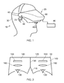
- the HMD comprises a frame 40, in this example formed of a rear strap and a top strap, and a display portion 50.
- the HMD of Figure 1 completely obscures the user's view of the surrounding environment. All that the user can see is the pair of images displayed within the HMD.
- the HMD has associated headphone earpieces 60 which fit into the user's left and right ears 70.
- the earpieces 60 replay an audio signal provided from an external source, which may be the same as the video signal source which provides the video signal for display to the user's eyes.
- a video signal is provided for display by the HMD.
- This could be provided by an external video signal source 80 such as a video games machine or data processing apparatus (such as a personal computer), in which case the signals could be transmitted to the HMD by a wired or a wireless connection.
- suitable wireless connections include Bluetooth (R) connections.
- Audio signals for the earpieces 60 can be carried by the same connection.
- any control signals passed from the HMD to the video (audio) signal source may be carried by the same connection.
- Figure 1 provides an example of a head-mountable display system comprising a frame to be mounted onto an observer's head, the frame defining one or two eye display positions which, in use, are positioned in front of a respective eye of the observer and a display element mounted with respect to each of the eye display positions, the display element providing a virtual image of a video display of a video signal from a video signal source to that eye of the observer.
- Figure 1 shows just one example of an HMD.
- an HMD could use a frame more similar to that associated with conventional eyeglasses, namely a substantially horizontal leg extending back from the display portion to the top rear of the user's ear, possibly curling down behind the ear.
- the user's view of the external environment may not in fact be entirely obscured; the displayed images could be arranged so as to be superposed (from the user's point of view) over the external environment. An example of such an arrangement will be described below with reference to Figure 4 .
- FIG. 1 A schematic plan view of how this is achieved is provided as Figure 2 , which illustrates the positions 100 of the user's eyes and the relative position 110 of the user's nose.
- the display portion 50 in schematic form, comprises an exterior shield 120 to mask ambient light from the user's eyes and an internal shield 130 which prevents one eye from seeing the display intended for the other eye.
- the combination of the user's face, the exterior shield 120 and the interior shield 130 form two compartments 140, one for each eye.
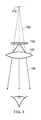
- a display element 150 and one or more optical elements 160 In each of the compartments there is provided a display element 150 and one or more optical elements 160. The way in which the display element and the optical element(s) cooperate to provide a display to the user will be described with reference to Figure 3 .
- the display element 150 generates a displayed image which is (in this example) refracted by the optical elements 160 (shown schematically as a convex lens but which could include compound lenses or other elements) so as to generate a virtual image 170 which appears to the user to be larger than and significantly further away than the real image generated by the display element 150.
- the virtual image may have an apparent image size (image diagonal) of more than 1 m and may be disposed at a distance of more than 1 m from the user's eye (or from the frame of the HMD). In general terms, depending on the purpose of the HMD, it is desirable to have the virtual image disposed a significant distance from the user.
- FIG. 4 An alternative arrangement is shown in Figure 4 .
- This arrangement may be used where it is desired that the user's view of the external environment is not entirely obscured. However, it is also applicable to HMDs in which the user's external view is wholly obscured.
- the display element 150 and optical elements 200 cooperate to provide an image which is projected onto a mirror 210, which deflects the image towards the user's eye position 220. The user perceives a virtual image to be located at a position 230 which is in front of the user and at a suitable distance from the user.
- the mirror 210 can be a substantially 100% reflective mirror.
- the arrangement of Figure 4 then has the advantage that the display element and optical elements can be located closer to the centre of gravity of the user's head and to the side of the user's eyes, which can produce a less bulky HMD for the user to wear.
- the mirror 210 can be made partially reflective so that the user sees the external environment, through the mirror 210, with the virtual image superposed over the real external environment.
- FIG. 5 An example of a pair of stereoscopic images for display to the left and right eyes is shown in Figure 5 .
- the images exhibit a lateral displacement relative to one another, with the displacement of image features depending upon the (real or simulated) lateral separation of the cameras by which the images were captured, the angular convergence of the cameras and the (real or simulated) distance of each image feature from the camera position.
- an HMD may be used simply to view movies and the like. In this case, there is no change required to the apparent viewpoint of the displayed images as the user turns the user's head, for example from side to side.
- the user's viewpoint need to track movements with respect to a real or virtual space in which the user is located.
- This tracking is carried out by detecting motion of the HMD and varying the apparent viewpoint of the displayed images so that the apparent viewpoint tracks the motion.
- Figure 6 schematically illustrates the effect of a user head movement in a VR or AR system.
- a virtual environment is represented by a (virtual) spherical shell 250 around a user. Because of the need to represent this arrangement on a two-dimensional paper drawing, the shell is represented by a part of a circle, at a distance from the user equivalent to the separation of the displayed virtual image from the user.
- a user is initially at a first position 260 and is directed towards a portion 270 of the virtual environment. It is this portion 270 which is represented in the images displayed on the display elements 150 of the user's HMD.
- the displayed portion of the virtual environment also moves so that, at the end of the movement, a new portion 290 is displayed by the HMD.
- the apparent viewpoint within the virtual environment moves with the head movement. If the head rotates to the right side, for example, as shown in Figure 6 , the apparent viewpoint also moves to the right from the user's point of view. If the situation is considered from the aspect of a displayed object, such as a displayed object 300, this will effectively move in the opposite direction to the head movement. So, if the head movement is to the right, the apparent viewpoint moves to the right but an object such as the displayed object 300 which is stationary in the virtual environment will move towards the left of the displayed image and eventually will disappear off the left-hand side of the displayed image, for the simple reason that the displayed portion of the virtual environment has moved to the right whereas the displayed object 300 has not moved in the virtual environment. Similar considerations apply to the up-down component of any motion.
- FIGS 7a and 7b schematically illustrated HMDs with motion sensing.
- the two drawings are in a similar format to that shown in Figure 2 . That is to say, the drawings are schematic plan views of an HMD, in which the display element 150 and optical elements 160 are represented by a simple box shape. Many features of Figure 2 are not shown, for clarity of the diagrams. Both drawings show examples of HMDs with a motion detector for detecting motion of the observer's head.
- a forward-facing camera 320 is provided on the front of the HMD. This does not necessarily provide images for display to the user (although it could do so in an augmented reality arrangement). Instead, its primary purpose in the present embodiments is to allow motion sensing. A technique for using images captured by the camera 320 for motion sensing will be described below in connection with Figure 8 .
- the motion detector comprises a camera mounted so as to move with the frame; and an image comparator operable to compare successive images captured by the camera so as to detect inter-image motion.
- Figure 7b makes use of a hardware motion detector 330.
- This can be mounted anywhere within or on the HMD.
- suitable hardware motion detectors are piezoelectric accelerometers or optical fibre gyroscopes. It will of course be appreciated that both hardware motion detection and camera-based motion detection can be used in the same device, in which case one sensing arrangement could be used as a backup when the other one is unavailable, or one sensing arrangement (such as the camera) could provide data for changing the apparent viewpoint of the displayed images, whereas the other (such as an accelerometer) could provide data for image stabilisation.
- Figure 8 schematically illustrates one example of motion detection using the camera 320 of Figure 7a .
- the camera 320 is a video camera, capturing images at an image capture rate of, for example, 25 images per second. As each image is captured, it is passed to an image store 400 for storage and is also compared, by an image comparator 410, with a preceding image retrieved from the image store. The comparison uses known block matching techniques (so-called "optical flow” detection) to establish whether substantially the whole image captured by the camera 320 has moved since the time at which the preceding image was captured.
- Localised motion might indicate moving objects within the field of view of the camera 320, but global motion of substantially the whole image would tend to indicate motion of the camera rather than of individual features in the captured scene, and in the present case because the camera is mounted on the HMD, motion of the camera corresponds to motion of the HMD and in turn to motion of the user's head.
- the displacement between one image and the next, as detected by the image comparator 410, is converted to a signal indicative of motion by a motion detector 420. If required, the motion signal is converted by to a position signal by an integrator 430.
- the HMD can detect head motion using a mechanical or solid state detector 330 such as an accelerometer.
- a mechanical or solid state detector 330 such as an accelerometer.
- the detector 330 can be better suited for use with higher frequency motion detection.
- a high image rate camera such as a 200 Hz capture rate camera
- a camera-based system may be more appropriate.
- the detector 330 could take the place of the camera 320, the image store 400 and the comparator 410, so as to provide an input directly to the motion detector 420. Or the detector 330 could take the place of the motion detector 420 as well, directly providing an output signal indicative of physical motion.
- position or motion detecting techniques are of course possible.
- a mechanical arrangement by which the HMD is linked by a moveable pantograph arm to a fixed point may be used, with position and orientation sensors detecting changes in the deflection of the pantograph arm.
- a system of one or more transmitters and receivers, mounted on the HMD and on a fixed point can be used to allow detection of the position and orientation of the HMD by triangulation techniques.
- the HMD could carry one or more directional transmitters, and an array of receivers associated with known or fixed points could detect the relative signals from the one or more transmitters.
- the transmitters could be fixed and the receivers could be on the HMD.
- transmitters and receivers examples include infra-red transducers, ultrasonic transducers and radio frequency transducers.
- the radio frequency transducers could have a dual purpose, in that they could also form part of a radio frequency data link to and/or from the HMD, such as a Bluetooth® link.
- Figure 9 schematically illustrates image processing carried out in response to a detected position or change in position of the HMD.
- the apparent viewpoint of the video being displayed to the user of the HMD is changed in response to a change in actual position or orientation of the user's head.
- a motion sensor 450 (such as the arrangement of Figure 8 and/or the motion detector 330 of Figure 7b ) supplying data indicative of motion and/or current position to a required image position detector 460, which translates the actual position of the HMD into data defining the required image for display.
- An image generator 480 accesses image data stored in an image store 470 if required, and generates the required images from the appropriate viewpoint for display by the HMD.
- the external video signal source can provide the functionality of the image generator 480 and act as a controller to compensate for the lower frequency component of motion of the observer's head by changing the viewpoint of the displayed image so as to move the displayed image in the opposite direction to that of the detected motion so as to change the apparent viewpoint of the observer in the direction of the detected motion.
- the image generator 480 may act on the basis of metadata such as so-called view matrix data, in a manner to be described below.
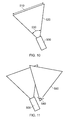
- Figure 10 schematically illustrates the capture of an image by a camera and Figure 11 schematically illustrates the reprojection of the captured image.
- a camera 500 captures an image of a portion 510 of a real-world scene.
- the field of view of the camera 500 is shown schematically as a generally triangular shape 520, such that the camera is at one apex of the generally triangular shape, the sides adjacent to the camera schematically indicate the left and right extremes of the field of view and the side opposite the camera schematically illustrates the portion of the scene which is captured.
- This schematic notation will be used in several of the following drawings.
- the view matrix may refer to the camera's position and/or orientation in space, either relative to a notional fixed point and orientation or expressed as changes with respect to the position and/or orientation applicable at a previous time (which may be the time associated with a preceding captured image, for example).
- the view matrix could be considered as the x, y and z spatial position of the camera along with its rotational orientation expressed as yaw, pitch and roll (general terms indicative of three orthogonal rotational degrees of freedom) and its viewing frustum (a general term indicative of the field of view of the camera, ranging between a wide-angle field of view and a narrow angle or telephoto field of view, and which may be expressed as an angular range corresponding to, for example, the angle 530 shown in Figure 10 ).
- the view matrix data need not comprise all of these data contributions. For example, in some arrangements, only a lateral rotational orientation (yaw) may be relevant.
- the choice of which data items to include within the view matrix data is therefore a matter for the system designer, taking into account the expected uses of the captured images and view matrix data.
- the view matrix data is stored in association with the captured image, for example as so-called metadata which is stored and/or transmitted as part of the overall image data package, for example by a camera apparatus such as that described below with reference to Figure 27 comprising an image capture device for capturing an image; a position and/or orientation detector for detecting the position and/or orientation of the camera apparatus at the time of capture of the image; and a metadata generator for associating metadata with the image, the metadata indicating the detected position and/or orientation of the camera apparatus at the time of capture of the image.
- a camera apparatus such as that described below with reference to Figure 27 comprising an image capture device for capturing an image; a position and/or orientation detector for detecting the position and/or orientation of the camera apparatus at the time of capture of the image; and a metadata generator for associating metadata with the image, the metadata indicating the detected position and/or orientation of the camera apparatus at the time of capture of the image.
- the camera 500 may be a stills camera or a video camera capturing a succession of images, separated by time intervals.
- Figure 11 schematically illustrates the reprojection of the image captured by the camera of Figure 10 according to a viewpoint of a viewer.
- the viewpoint 540 is schematically illustrated by an eye symbol and a generally triangular shape 550 which is similar to the triangular shape 520 discussed above.
- a process is carried out which relates the view matrix (as discussed above) of the viewpoint to the view matrix of the camera 500. Examples of such techniques will be described with reference to Figures 12 and 13 . Further examples are discussed in Seitz: "Image Based Transformation of Viewpoint and Scene Appearance", PhD Dissertation, Computer Sciences Department Technical Report 1354, University of Wisconsin - Madison, October 1997 , the content of which is incorporated herein by reference.
- Figure 12 schematically illustrates an image rotation from a first view matrix 560 to a second view matrix 570.
- Reprojection of this type involves simply rotating and scaling the image so as to correct for any differences in field of view and orientation between the view matrix of the camera and the view matrix of the user viewpoint. Examples of this type of reprojection will be discussed below with reference to Figures 16 and 17 .
- Figure 13 schematically illustrates an image rotation and translation from a first view matrix 580 to a second view matrix 590.
- the processing is slightly more involved, and may also use a depth map, indicating the image depth of different image features in the captured image, to allow the user viewpoint to be translated with respect to the viewpoint of the camera. Examples of the use of a depth map will be discussed below with reference to Figures 18-20 .
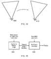
- Figure 14 schematically illustrates a latency issue with HMD image display.
- the position and/or orientation of an HMD can be used, for example as discussed with reference to Figure 9 , so that an image for display is rendered according to the detected position and/or orientation of the HMD.
- the arrangement discussed with reference to Figure 9 involves detecting the current position and/or orientation of the HMD and rendering an appropriate image for display.
- FIG 14 consider a situation in which the user's viewpoint is rotating (in a clockwise direction as illustrated schematically in Figure 14 ) from a first viewpoint 600 to a second viewpoint 610, over the course of a time interval of the order of an image repetition period of the image displays used in the HMD (for example, 1/25 second). Note that the two representations in Figure 14 are shown side-by-side, but this is for the purposes of the drawing rather than necessarily indicating a translation of the user viewpoint (although some translation could be involved between the two viewpoints).
- the position and/or orientation of the HMD is detected when the HMD is at the viewpoint 600.
- the next image for display is then rendered, but by the time that image is actually displayed, the viewpoint has rotated to the viewpoint 610.
- the result is that the image is displayed is incorrect for the user's viewpoint 610 at the time that image is displayed. This can provide a subjectively poorer experience for the user, and may possibly lead to disorientation or even nausea on the part of the user.
- Figure 15 is a schematic flow chart illustrating an image processing technique. The technique will first be discussed at a high level, and then more detail will be given below.
- the features of the technique shown in Figure 15 involve capturing or rendering an image (at a step of 620) according to the view matrix of the camera (in the case of a captured image) or the view matrix of the HMD (in the case of an image rendered by, for example, a computer game).
- the image would be rendered according to the view matrix corresponding to the viewpoint 600 in Figure 14 .
- the technique involves detecting an initial position and/or orientation of the viewer's head and generating an image for display according to the detected position and/or orientation.
- the image is then transmitted or passed to the HMD along with metadata defining that view matrix (that is to say, the view matrix according to which the image was captured or first rendered).
- the HMD view matrix is again detected (in other words, detecting a current position and/or orientation of the viewer's head at a time at which the image is to be displayed) and, at a step 630, the image is reprojected based on the metadata indicating the original view matrix and the view matrix detected from the HMD at the time of display (in the terminology of Figure 14 , this would be the view matrix corresponding to the viewpoint 610, so that the technique involves associating metadata with the generated image, the metadata indicating the initial position and/or orientation of the viewer's head). So, the technique involves reprojecting the generated image according to any differences between the initial position and/or orientation and the current position and/or orientation of the viewer's head and displaying the reprojected image using the display.
- the view matrix of the camera is generally not within the control of the display arrangements and so this technique provides a way of compensating for differences between the two view matrices.
- image rendering however, the issues are slightly different.
- a significant feature is that the time taken to process a reprojection operation can be much less than the time taken for a full rendering operation to generate an output image.
- the rendering operation takes place relative to a viewpoint (such as the viewpoint 600) which is correct at the time that the rendering operation is initiated, but the viewpoint is then adjusted (to the viewpoint 610, for example) at the time of display.
- a viewpoint such as the viewpoint 600
- the viewpoint is then adjusted (to the viewpoint 610, for example) at the time of display.
- the technique can involve receiving an image and associated metadata, detecting a current position and/or orientation of the viewer's head at a time at which the image is to be displayed, reprojecting the received image according to any differences between the position and/or orientation indicated by the metadata and the current position and/or orientation of the viewer's head, and displaying the reprojected image.
- timing of the process can proceed as follows:
- the image is then transferred to the HMD. This can take a period of zero or more seconds (the period would be zero if, for example, the image had been rendered at the HMD). But in general, a period T delivery is noted for the time taken to deliver the image to the HMD ready for display.
- the HMD view matrix data is again detected. This could correspond to the required display time, in which case (according to the derivation below) the image would be displayed late by an amount T reproj , or it could be carried out at a time equal to a display time T display - T reproj . In either case it is carried out at a time dependent upon a required display time.
- the image is then reprojected (at the step 630) to account for differences between the initial and the latest view matrices.
- the time period taken for the reprojection is T reproj , assumed here to be much less than (or at least less than) T render .
- the image is then displayed at a time: t 0 + T render + T delivery + T reproj .
- the detected initial position is detected at a latest time, allowing for the image generating latency and the image reprojection latency, to allow for the display of the reprojected image at the display time.
- Figure 16 schematically illustrates the rotation of an HMD viewpoint 650 in a clockwise direction.
- an image generated at the step 620 is represented by an image 660 in Figure 16
- an image generated at this step 630 is represented by an image 670 in Figure 16
- the two images may be represented side-by-side from the point of view of the user. (Note that in Figure 17 , a small vertical displacement is shown just to allow the different images to be distinguished from one another in the drawing).
- a "subtraction" operation is carried out, which is a schematic term to illustrate the operation of detecting the overlap between the required display position of the image 670 and the actual position of the image 660, so as to display within the image 670 the overlapping portion 680 (shaded in Figure 17 ) of the image 660.
- the reprojecting comprises detecting an overlapping portion between the generated image and the required reprojected image, and reproducing the overlapping portion as part of the reprojected image.
- the missing areas in the image 670 may be masked or filled in using image data from, for example, a panoramic image captured or prepared for this purpose and stored by the display arrangement. So, embodiments of the technique can therefore comprise filling portions of the reprojected image other than the overlapping portion with image material from a further image source.
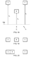
- Figure 18 schematically illustrates a depth map which may be derived, for example, from image data captured by a 3-D (binocular) camera or a so-called Z-camera, or which may be generated as part of the operation of a computer games machine's rendering engine.
- FIG. 18 In the schematic example of Figure 18 , three image objects labelled as objects A, B and C, are shown at respective image depths measured from an arbitrary depth position 700 of z A , z B and z C . Two potential viewpoints are shown, labelled as a viewpoint v 1 and a viewpoint v 2 respectively.
- Figures 19 and 20 schematically illustrate portions of images according to the viewpoint v 1 and the viewpoint v 2 respectively.
- the depth of each of the image objects is taken into account in generating the images.
- this technique can also be used at a reprojection stage such as that defined by the step 630 discussed above, so that image objects may be moved relative to one another in the reprojected image according to their respective image depths.
- the technique can involve providing depth data indicating the image depth of one or more image features, and the reprojecting can comprise repositioning one or more image features within the reprojected image according to the depth data.
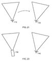
- Figure 21 schematically illustrates a technique for image rendering and reprojection to compensate for HMD motion.
- a user viewpoint moves or rotates from a viewpoint 710, detected as part of the step 620 of Figure 15 , to a viewpoint 720 detected as part of the step 630 of Figure 15 and according to which the image for display is reprojected. In this way, an image according to the correct viewpoint 720 is displayed to the user.
- Figure 22 is a schematic flowchart relating to the technique shown in Figure 21 .
- process steps 800, 810, 820, 830, 840 and 850 are shown.
- the steps 800, 810 and 820 correspond generally to the step 620 of Figure 15 .
- the remaining steps 830, 840 and 850 correspond generally to the step 630 of Figure 15 .
- each of the steps in Figure 22 could be carried out immediately (or substantially immediately) in response to completion of the preceding step.
- the current position of the HMD (corresponding to the position 710 of Figure 21 ) is detected and, at the step 810, is stored (for example in a temporary working memory forming part of the HMD or the computer games machine).
- an image for display is rendered according to the viewpoint 710.
- the HMD position is again detected at the step 830 which, in this example, will detect the position 720.
- the image for display is reprojected as discussed above at the step 840 and is displayed to the user at the step 850.
- the timing of the steps could be in accordance with the example timings discussed above.
- Figure 23 schematically illustrates a technique for image capturing and reprojection to compensate for different camera and HMD positions.
- a camera viewpoint 730 is different to an HMD viewpoint 740.
- Figure 24 is a schematic flowchart relating to the technique shown in Figure 23 .
- process steps 900, 910, 920, 930, 940 and 950 are shown. Of these, the steps 900 and 910 correspond generally to the step 620 of Figure 15 . The remaining steps 920, 930, 940 and 950 correspond generally to the step 630 of Figure 15 .
- the current position of the camera (corresponding to the position 730 of Figure 23 ) is detected and, at the step 910, is transmitted as metadata along with the captured image.
- the HMD position is detected at the step 920 which, in this example, will detect the position 740.
- the image for display is reprojected as discussed above at the step 930 and is rendered (at the step 940) for display to the user at the step 950.
- the data-processing operations described above may be carried out at the video signal source 80 (for example, a computer games machine) and/or the HMD (in terms of all of the steps of Figure 22 and the steps 920...950 of Figure 24 ).
- the division between processing at the HMD and processing at the source 80 is a matter for the system designer; it may be desirable to reduce the size, weight and power consumption of the HMD for user comfort, which would make it appropriate to move as much processing as possible to the source 80.
- some of the processing may take place entirely at the HMD. In either instance, the processing may be carried out by appropriate programmable hardware operating under software control, for example.
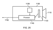
- FIG. 25 schematically illustrates a camera 1100 having this functionality.
- the camera 1100 comprises a lens arrangement 1110, and image sensor 1120 arranged to receive light through the lens arrangement 1110 and convert the light into an image signal, a position, orientation and/or motion detector 1130, which may be of the types discussed above in connection with detecting the HMD's position, orientation and/or motion, and a processor 1140 operable to carry out at least the steps 900, 910 using data from the detector 1130 and to output an image signal 1150 having associated viewpoint metadata as discussed above.
- the image data for this process may be simply derived from the sensor 1120, so avoiding the need for a separate detector 1130.
- an immersive video display such as a head-mounted display (HMD) is capable of reproducing images life-sized and in their correct orientation to the viewer.
- the image reprojection can be performed rapidly and at the latest time just before display. This can reduce unwanted image movement caused by rendering latency.
- this technique can stabilise camera motion reducing viewer sickness and maintains the real world orientation of objects, improving immersion and realism.
- a single HMD could be used to reproject both interactive content and broadcast TV signals using the same technology. Some frame borders may be seen if the viewer is looking in a different direction to the camera, though this could be mitigated using supplementary panoramic still images to fill the gaps.
- Embodiments of the disclosure can also address issues relating to video captured by a shaky camera, for example by a hand-held camera or a camera subject to outside influences on its motion, such as a camera mounted on a mechanical device or in the path of wind currents.
- a shaky camera for example by a hand-held camera or a camera subject to outside influences on its motion, such as a camera mounted on a mechanical device or in the path of wind currents.
- reprojection is performed at the time of display using the techniques described above. In this way, a central region of the image can be compensated for camera motion and appear steady to the viewer, though the outer border of the image may move around as a result of the compensation.
- the example image shown in Figure 26 is a lower-resolution background scene provided by an image signal displayed across the whole of the display screen, and a higher resolution insertion image provided by an image signal superimposed so as to replace a part of the lower resolution background scene.
- the example schematically illustrated in Figure 26 might form part of a video or a videogame relating to driving along a road surrounded by trees (shown very schematically in Figure 26 ).
- a background scene is generated and displayed at a lower resolution than an insertion image 1160 which is generated and displayed at a higher resolution.
- the insertion image 1160 relates to parts of the overall scene which the user will be concentrating on, namely (in this example) the road immediately ahead and any oncoming vehicles.
- the remaining background image (after insertion of the insertion image) relates to other parts of the overall scene which are less important to the user's attention.
- This disparity in image resolution is used is because of the high processing overhead in generating an overall scene covering the entire display at a high resolution. Instead, the background may be generated at a lower resolution (and may be arranged so as to change less frequently than the insertion image) so as to save on processing overhead.
- a further example relates to a video game, such that the overall background image could represent some or all of a virtual world.
- the scene relating to specific game action by a player is reprojected into the correct position within the virtual world as the insertion image.
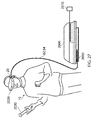
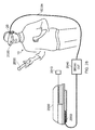
- FIG 27 schematically illustrates a user wearing an HMD connected to a Sony® PlayStation 3® games console 2000 as an example of a base device (corresponding to the external video source 80 of Figure 1 ), a further example of a base device is a PlayStation 4® games console.
- the games console 2000 is connected to a mains power supply 2010 and (optionally) to a main display screen (not shown).
- a single physical cable is provided which fulfils the functions of the cables 82, 84.
- a hand-held controller 2030 which may be, for example, a Sony® Move® controller which communicates wirelessly with the games console 2000 to control (or to contribute to the control of) game operations relating to a currently executed game program.
- the video displays in the HMD 20 are arranged to display images generated by the games console 2000, and the earpieces 60 in the HMD 20 are arranged to reproduce audio signals generated by the games console 2000. Note that if a USB type cable is used, these signals will be in digital form when they reach the HMD 20, such that the HMD 20 comprises a digital to analogue converter (DAC) to convert at least the audio signals back into an analogue form for reproduction.
- DAC digital to analogue converter
- Images from the camera 2050 mounted on the HMD 20 are passed back to the games console 2000 via the cable 82, 84.
- signals from those sensors may be at least partially processed at the HMD 20 and/or may be at least partially processed at the games console 2000. The use and processing of such signals will be described further below.
- the USB connection from the games console 2000 also provides power to the HMD 20, according to the USB standard.
- FIG 28 schematically illustrates a similar arrangement in which the games console is connected (by a wired or wireless link) to a so-called "break out box" acting as a base or intermediate device 2040, to which the HMD 20 is connected by a cabled link 82, 84.
- the breakout box has various functions in this regard.
- One function is to provide a location, near to the user, for some user controls relating to the operation of the HMD, such as (for example) one or more of a power control, a brightness control, an input source selector, a volume control and the like.
- Another function is to provide a local power supply for the HMD (if one is needed according to the embodiment being discussed).
- Another function is to provide a local cable anchoring point.
- the break-out box 2040 is fixed to the ground or to a piece of furniture, but rather than having a very long trailing cable from the games console 2000, the break-out box provides a locally weighted point so that the cable 82, 84 linking the HMD 20 to the break-out box will tend to move around the position of the break-out box. This can improve user safety and comfort by avoiding the use of very long trailing cables.
- an HMD may form part of a set or cohort of interconnected devices (that is to say, interconnected for the purposes of data or signal transfer, but not necessarily connected by a physical cable).
- processing which is described as taking place “at” one device, such as at the HMD could be devolved to another device such as the games console (base device) or the break-out box.
- Processing tasks can be shared amongst devices.
- Source signals, on which the processing is to take place, could be distributed to another device, or the processing results from the processing of those source signals could be sent to another device, as required. So any references to processing taking place at a particular device should be understood in this context.
- the user's viewpoint needs to track movements with respect to a real or virtual space in which the user is located.
- This tracking is carried out by detecting motion of the HMD and varying the apparent viewpoint of the displayed images so that the apparent viewpoint tracks the motion.
- Figure 29 depicts an image that is centred on a point 1000 at an infinite distance from a particular viewpoint.
- the centre of the image has been defined to be the infinitely distant point 1000 so that a gauge of the angle of rotation can be made (by the reader of this description) in comparison to Figure 30 .
- the image is generated for the position and/or orientation of a viewer's head at an initial time or for a predetermined viewpoint, and has been pre-distorted in such a way that when it is displayed to the user of the display device it will appear as a flat image that may occupy the user's entire field of view.
- the example image contains a lattice of reference lines 1004, 1006 that act as markers to help identify the motion of the generated image in response to a detected head motion of the user.
- the horizontal reference lines 1004 link pixels that would appear on the same line of the image if it were undistorted, which is to say that each such horizontal line links pixels of common vertical position within the undistorted image.
- vertical reference lines 1006 on the image each link pixels that would be in the same column of pixels in the undistorted image (i.e. equal horizontal position).
- the reference lines are therefore useful not only as a reference for inter-image motion, but also to demonstrate the distortion of the image that is applied to account for the optical properties of the HMD device.
- An inner circle 1010 and an outer circle 1020 are also present in the image, also to help distinguish (in the context of the present description) the motion between successive images.
- the image In order for the image to be displayed correctly to the viewer, it is manipulated to appear in the correct position with the correct orientation relative to that of the viewer's head. In order to simulate a motion that complements that of the viewer's head the image displayed is displaced in the opposite direction to that of the motion. Note that as discussed above, the movement is detected by a motion detecting unit on the HMD such as a camera or accelerometer.
- a motion detecting unit on the HMD such as a camera or accelerometer.
- providing a new image in response to a new head position and/or orientation can be achieved by several methods; a first example is that the video image source could generate a new image that appears to be at the new viewpoint of the HMD user's head as sampled at or before the time at which generation of the new image is initiated - but this may be ineffective in terms of the time delay that is introduced (T render + T delivery as discussed earlier) as the time taken for a new image to be generated may be long enough that the user's head has moved significantly further and thus the image as generated is not correct at the time of display.
- a second method that may be employed is reprojection, also as discussed in detail above.
- an already-generated image (which may have been generated according to the latest available head position and/or orientation data at the time that generation was initiated) is further manipulated in order to appear to be seen from the correct viewpoint according to position and/or orientation data acquired just as the reprojection process is started.
- This can reduce the temporal error (between the time at which the latest position and/or orientation data is acquired and the time at which the resulting image is displayed) to T reproj as discussed above, where T reproj is somewhat less than T render + T delivery .
- reprojection may be difficult to implement in some applications because of the extra processing that is required in generating a first image and then producing a reprojected image based on this.
- a third method (which is used in the presently described embodiment) is to use an approximation of the reprojection process.
- a pixel mapping technique is employed which allows an approximation of a reprojection of an image in response to a change in viewpoint to be made by shifting pixels about the display in response to the detected head motion.
- This method does not require the generation of a new second image or the full use of geometrical reprojection, and therefore reduces the processing power required to display an image at the correct position and/or orientation.
- the time T approximation taken to perform this process can be even lower than the time T reproj taken to perform reprojection, the amount of head movement which is likely to occur (and which needs to be compensated for by this process) can be lower than that applicable to reprojection.
- This in turn can assist with the use of an approximation process, as approximating small effects can be easier than approximating large effects, simply because any errors introduced by the approximation process are likely to be less noticeable.
- Figure 30 schematically shows the HMD user's view (or rather, what the HMD user's view should be) of the image of Figure 29 after the user's head has rotated laterally to the left.
- the vertical lines 1006 in the image may be offset by a uniform amount across the image in both the horizontal and vertical directions, in response to a detected head motion in the opposite direction.
- the pixels may also be offset such that each row of pixels is offset by different amounts left or right to that of other rows of pixels in the image. This is again in response to a detected motion of the head in the opposite direction, and the technique shall be discussed in more detail below.
- This process may also be carried out for the detected vertical head motion of the HMD user, but as the motion of the head in this plane is limited relative to that of yaw by physical considerations of neck motion (which is to say, the available range of side to side head rotation for the average person is greater than the available range of up /down motion), it is considered adequate to simply employ a vertical translation of the image rather than a full pixel mapping method. This reduces the amount of processing required, reducing the time delay between an image being generated and displayed. Further to this, a correction for the roll of the head (rotation of the head in the plane parallel to the displayed image) is considered unnecessary on this scale as it has little effect on the centre of the image (noting once again that only rotations taking place in the time period T approximation are relevant).
- the accuracy of the approximations may also be improved in that the reprojection approximation method is more readily applied to higher frame rate videos than that to which standard reprojection methods are suited, such as 120Hz displays.
- This increased frame display rate means there is a shorter time and therefore less movement between frames, further justifying the approximations that are made. For instance, in the reduced time between frames the possible vertical motion of the head is even smaller than in the originally considered processing time and therefore the approximation of this motion as a simple translation is more accurate due to the small angles involved.
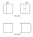
- Figures 31 a and b are schematic illustrations of possible manipulations to the generated image in order for it to carry out the approximation of reprojection.
- Figure 31a shows a horizontal translation of each of the pixels in a column 1050 of the generated image towards the right side of the image, in response to the detected head motion of the user to the left. The same translation is also applied to other columns of pixels in the rest of the image uniformly.
- Figure 31b is an illustration of offsetting pixels in conjunction with the translation of the image. This offset is undertaken such that all of the pixels that share a horizontal line on the image are shifted by the same amount. The lines closest to the top and bottom of the image have applied a smaller offset than those in the centre of the image in order to give the correct appearance as discussed above.
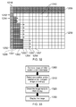
- Figure 32 is a diagram showing an example of a pixel by pixel displacement of an image in order to provide an approximation of the reprojection process which would be required to correct for the change of a viewer's head position and/or orientation.
- Each square 1240 in the Figure represents a pixel, with each different translation of the pixels being distinguished by shading as detailed below.
- the Figure depicts a portion of an image to be displayed, for example the top left corner in the case of the viewer moving their head slightly upwards and to the left, and the motion of the pixels themselves.
- the approximation of the compensation is provided by a pixels shift downwards by an amount dependent upon the magnitude of the vertical head rotation in the period T approximation .
- all of the pixels in the image are translated uniformly downwards to account for a user tilting their head upwards.
- the magnitude of the displacement in this example is two pixels, so that two rows of pixels (drawn as a shaded region 1200) are blank, and all other pixels in the image correspond to pixels which were two rows higher in the image before the present process was applied.
- Compensation of lateral (side to side) rotation during the time period T approximation can be compensated by a horizontal translation in which some or all of the pixels in the image are translated leftwards or rightwards.
- the horizontal shift which is drawn in this example towards the right (in response to a leftward head motion), may have a component common to all rows of pixels, and a component which varies between rows.
- the component common to all rows is a shift of one pixel to the right, so that a leftmost column 1210 of pixels is blank, and all other pixels in the image correspond to pixels which were at least one pixel position to the left in the original image (before the present process was applied).
- the common component could be zero.
- at least some pixels are further offset horizontally, which is to say that their offset is greater than or at least different to the component common to all rows of pixels. The magnitude of the offset varies with vertical row position.
- a top row 1212 of pixels does not undergo any translation beyond the common component discussed above.
- the next row below (a row 1214) is further translated rightwards by a small amount (one pixel in this example).
- the further displacement generally increases for rows closer towards the centre of the image, noting again that the portion represented by Figure 32 is indicative of an upper left corner region of a larger image.
- the rows of pixels at the bottom of Figure 32 are translated by the greatest amount (of those rows shown), representing a further displacement of three pixels.
- the result is a manipulated image that fills the area 1230 and is ready for display by the HMD.
- the lower portion of the image is not shown in Figure 32 , but the pixel displacements would generally tend to decrease towards the bottom of the image (for other than zero or near-zero changes in position and/or orientation). This provides an approximation of the reprojection process.
- the displacements may increase monotonically on moving from the top or bottom of the image towards the vertical centre. Multiple adjacent rows of pixels may have the same displacement.
- the horizontal translations are dependent upon the difference between the initial position and/or orientation of the HMD and the detected (later) position and/or orientation at the time at which the image is to be displayed. Applying the horizontal displacements involves applying a lateral displacement to at least a subset or rows of pixels, the lateral displacement depending upon the difference in position and/or orientation between an initial and a current (time of display, or time or initiation of the reprojection approximation) value.
- the lateral pixel displacement may also depend upon the pixel row.
- the step 1310 may also be applied.
- Another possibility is to introduce the so-called 'leaking' of pixel values. This is when pixel values from the end of one row of pixels (for example, the far right hand side of row 1212) are reproduced at the start of the next line (for example, the far left hand side of row 1214). This may be implemented in either direction, so for example the far right pixel of row 1214 may be reproduced in the first pixel of row 1212.
- the leaking may also occur from either side of the row (such as a left side to left side mapping) or from rows that are not adjacent to the row being rendered.
- a third possible method to populate unoccupied pixel positions is to create 'fake' data.
- a first option for this is to duplicate the first occupied pixel position into the positions before it, such that every pixel in a line is the same until after the first originally populated pixel position is reached.
- an example of this corresponds to the positions 1250-1253 all having the same value as the pixel 1254.
- Pixel values which, according to the translations under discussion, would be translated out of the active images area may simply be discarded.
- the approximation technique as discussed above may simply be used in place of the step 840 in Figure 22 or the step 930 in Figure 24 discussed above.
- a processing step comprises applying a lateral pixel displacement to at least a subset of rows of pixels, the lateral pixel displacement depending on a difference in lateral rotation between the initial orientation and the detected current orientation of the head mountable display device.
- the lateral displacement may be different for two or more subsets or groups of rows of pixels.
- the lateral displacement may be greater for a subset of pixel rows towards a vertical centre of the image than for another subset of pixel rows towards a top or bottom of the image.
- the processing step may comprise applying a vertical pixel displacement to the image in dependence upon a difference in vertical rotation between the initial orientation and the detected current orientation of the head mountable display device.
- the processing step may comprise generating the pixel displacements as a function of pixel position in the image and the difference between the initial orientation and the detected current orientation of the head mountable display device.
- Figure 33 is a flow chart that exemplifies parts of the method described earlier (with reference to Figures 22 and 24 ) by which the manipulation of a video image can be performed.
- an image is generated by a video image source (for example, the games console 300 of figure 27 or a camera such as the camera of Figure 25 ) with a viewpoint corresponding to an initial position and/or orientation.
- a video image source for example, the games console 300 of figure 27 or a camera such as the camera of Figure 25
- This position and/or orientation may be either predetermined by the application that is running on the console, or based upon the camera position, or based upon the detected position and/or orientation of the user of the connected HMD device, for example at the time that generation of the image is initiated.
- a new position of the user is detected (for example, just before the display time for that image) and the image to be displayed is reprojected (or a reprojection is approximated as discussed above) to correct for this change in position.
- the reprojected image or the image with an approximation of reprojection
- the distorted image is displayed at the HMD with the correct distortion and viewpoint.
- the step 1300 is similar to the steps 800-820 of Figure 22 or the step 900 of Figure 24 .
- the step 1310 is similar to the steps 830-840 of Figure 22 or the steps 920-930 of Figure 24 .
- the step 1320 does not have an equivalent in Figures 22 or 24 .
- the step 1330 is similar to the steps 850 ( Figure 22 ) or 950 ( Figure 24 ).
- Figure 33 therefore provides an example of an image processing method for a head mounted display device, operable in respect of an image generated for display by a head mountable display device according to an initial position and/or orientation of a viewpoint, the method comprising:
- the video image source generates a distorted image, for example in respect of a predetermined viewpoint, a current camera viewpoint or a detected position and/or orientation of the HMD device in a step 1400.
- the distortion of the image is such that it compensates for the optics of the HMD device as discussed above in order to produce an image that may be displayed correctly.
- the step 1400 encompasses either generating the image in a distorted form, or generating it as a conventional image and then applying a distortion.
- a step 1410 the current position and/or orientation of the user of the HMD is detected and the distorted image is manipulated, according to a pixel mapping process approximating a reprojection process, as detailed earlier in the present text, with translations of the pixels in the horizontal and/or vertical directions to simulate a rotation of the viewpoint.
- the image is displayed to the user of the HMD at a step 1420.
- the yaw information can be based upon position and/or orientation data supplied by any of the head position and/or orientation detection arrangements described earlier, from which is subtracted the position and/or orientation at which the image was captured or generated, so as to provide a yaw amount for which correction is required at the step 1410.
- Figure 35 illustrates a possible method for implementing the image manipulation as described above.
- a buffer 1700 stores a generated image (in this example, a distorted image to compensate for the HMD optics), or a part of the generated image, that is to be displayed at the HMD.
- An example pixel 1710 is shown.
- the yaw data 1730 as detected by the HMD (not shown) is input into an address mapping unit 1720 to implement the pixel mapping technique to account for the motion of the HMD.
- the address mapping information is then used to read pixels from pixel positions in the buffer 1700 and write those pixels to a second buffer 1740, so that pixels of image stored in the buffer 1700 are translated to new locations as determined by a pixel mapping provided by the address mapping unit 1720.
- a pixel 1750 which corresponds to the pre-mapping pixel 1710 form the buffer 1700, but now at a different image position according to the mapping imposed by the address mapping unit 1720.
- the contents of the buffer 1740 may then be read out for the image to be displayed to the user.
- FIG. 36 An alternative to this arrangement is schematically illustrated in Figure 36 , which uses only a single buffer 1800 rather than the two buffers of Figure 35 .
- the buffer 1800 may contain the whole of the generated image, or only a few rows 1860 of pixels; for example, a few most recent rows at any time.
- the number of rows stored could be linked to the expected or allowable maximum pitch change of the HMD in the processing time T approximation of the image. For example, if a maximum change in pitch was determined to correspond to a maximum 10 row displacement of the pixels in either direction, then it is possible that only 21 lines are stored in the buffer as it would then be possible to map between all of the possible variations in vertical displacement with this amount of buffered data.
- the amount of data to buffer is kept as low as possible, while still allowing the required pitch corrections to be applied, in order to maintain a low latency (and so a low value of T approximation ).
- An address mapping unit 1840 of Figure 36 may be configured to provide the address mapping information 1850 to control either the writing of image data 1810 into the buffer 1800 or reading of image data from the buffer, so as to provide a corrected image 1890.
- the address mapping information 1850 is used upon writing image data into the buffer 1800 .
- row number data 1830 of the pixels that are being considered are input to the address mapping unit along with the detected yaw data 1820 (that is to say, the difference between the position and/or orientation relating to the generation or capture of the image and the current position and/or orientation of the HMD).
- the address mapping unit generates address mapping information 1850 so as to cause the image data 1810 to be stored in the buffer 1800 with the pixels already displaced according to the head motion, for example a pixel relating to a pixel position 1870 of the originally generated image may be stored at a pixel position 1880 instead.
- the HMD display (not shown) is then able to read the image data from the buffer and display it without further mapping as the correct image 1890 for the detected change in position and/or orientation of the HMD.
- a second implementation of the arrangement of Figure 36 is one in which the address mapping information 1850 is used upon reading of the image data 1810 from the buffer 1800. Similar to the first implementation, the row number information 1830 is provided along with the yaw data 1820 to the address mapping unit 1840 in order to produce address mapping information 1850 that describes the translation of the pixels in the image to account for the detected motion of the HMD. The address mapping information 1850 is then used upon the reading of the image from the buffer 1800, such that the pixel to be displayed at position 1880 is instead read from the position 1870 in the buffer 1800. This results in a corrected image 1890 being displayed to the viewer in response to their position and/or orientation.
- the address mapping function applies a lateral and, if pitch is also taken into account, vertical pixel shift to pixel positions depending on the difference in head position and/or orientation between the image generation and the image display times.
- the horizontal and vertical components of the shift may be derived separately as follows.
- the horizontal component of the shift varies not only according to the yaw value, but also from row to row.
- the pixel shift for each row can be found by the address mapping unit using a look-up table.
- a single look-up table just giving a base shift value as a function of row number (or ranges of row numbers) could be used, with the result being scaled by the address mapping unit according to a value (yaw variation * constant), or a two-dimensional look-up table could be used giving pixel shift as a function of both yaw amount and row number (or ranges of row numbers).
- Figure 37 is a schematic flowchart relating to the operation of the apparatus shown in Figure 35 or Figure 36 .
- data about the detected head motion (in this case, yaw) is supplied to the address mapping unit 1720 at a step 1500, and is used to relate the magnitude and direction of an angular head motion to a magnitude and direction of pixel displacement.
- the address mapping unit processes the input yaw data in a step 1510 in order to output a set of pixel shift data that produces the appropriate mapping to correspond to the detected motion of the users head.
- a step 1520 the mapping data is used as discussed above - for example to read out the pixels of the generated distorted image from a different location to that at which they were stored, or to write pixels into a different location in a buffer, or to transfer pixels from one buffer to another but with a location translation. This results in an image in which the pixels have been shifted from their original positions as originally generated. The shift that is applied is such that the yaw of the user's head will be accounted for.
- Figure 38 is an example of an image buffer 1900 usable as the buffer memories 1700, 1740 or 1800 in respect of a system in which there is no manipulation of the generated image in response to a detected change in pitch.
- the means that the image buffer 1900 may take the form of a one line pixel buffer, as extra lines are not required to enable pixel mapping between them.
- the buffer may be arranged to store a number of pixels that equates to a predetermined amount of yaw (for example, large enough that sufficient pixels are able to be buffered to deal with approximately 5° of yaw, which is considered the upper limit for human head motion for lateral rotations in an image period). Storing this many pixels in the buffer therefore allows for a sufficient degree of pixel mapping to accommodate the predetermined limits on head motion.
- the algorithm can be executed using a row (scanline)-based 2D display controller or a shader.
- the first sampler input is the distorted 1080p image as coming from the games machine.
- the second sampler input is a 1D lookup texture described below.
- the float4 constant contains the image (x,y) shift in pixels and the yaw delta (difference between initial and current positions/orientations), foe example expressed in degrees.
- the 1 D lookup texture is used for per-scanline shifting of the image to achieve the following: (a) It contains an x pixel shift value for each scanline; and (b) The shift is in number of pixels shifted per 1 degree yaw, divided by the screen width in pixels.
- Example C++ code to set up the shader constant (shaderConst) is shown below:
- Example shader code to run the algorithm is as follows:
- the algorithm can be performed at scan-out in the following way: (a) Pre-calculate display fetch positions for each scan line; and (b) Handle display fetch per scan line using the pre-calculated data.
- the pre-calculated data for each scan line may contains a fetch address (where to start reading the source image) and a delay time before fetching (how long we wait before we start fetching).
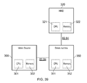
- FIG 39 schematically illustrates example hardware which may be used to implement the current techniques, and relates to apparatus features shown schematically in Figures 27 and 28 .
- the HMD device 320 is connected to the break out box 350 by the cable(s) 82, 84, with each of the HMD and break out box containing a processing unit (321,351 respectively) and a memory unit (322, 352 respectively).
- the break out box is then further connected to a video source 350, for example a games console, via further cable(s) 82, 84.
- the video source also has its own processor 301 and memory unit 302.
- the processing of the image as described above may be carried out by any of the three processors (301,321, 351) in conjunction with their respective memory unit, or may be distributed amongst them.
- the present process lends itself to being carried out by the processor 321, that is to say the process is carried out at the HMD 320.
- the hardware may be arranged without the break out box 350, such that the HMD 320 may be directly connected to the video source 300.
- Figure 39 therefore provides an example of an image processing apparatus operable to process an image generated for display by a head mountable display device according to an initial position and/or orientation of a viewpoint, the apparatus comprising:
- the present disclosure provides a convenient technique for manipulates the standard distorted games machine output, being easy to implement on low cost, simple hardware, which in turn lends itself to being implemented at the HMD.
Landscapes
- Engineering & Computer Science (AREA)
- Multimedia (AREA)
- Physics & Mathematics (AREA)
- General Physics & Mathematics (AREA)
- Optics & Photonics (AREA)
- Theoretical Computer Science (AREA)
- Human Computer Interaction (AREA)
- Computer Graphics (AREA)
- Signal Processing (AREA)
- Computer Hardware Design (AREA)
- General Engineering & Computer Science (AREA)
- Software Systems (AREA)
- Computing Systems (AREA)
- Geometry (AREA)
- Computer Vision & Pattern Recognition (AREA)
- Controls And Circuits For Display Device (AREA)
- Processing Or Creating Images (AREA)
Applications Claiming Priority (1)
| Application Number | Priority Date | Filing Date | Title |
|---|---|---|---|
| GB1413400.1A GB2528699B (en) | 2014-07-29 | 2014-07-29 | Image processing |
Publications (2)
| Publication Number | Publication Date |
|---|---|
| EP2979736A2 true EP2979736A2 (fr) | 2016-02-03 |
| EP2979736A3 EP2979736A3 (fr) | 2016-07-13 |
Family
ID=51587389
Family Applications (1)
| Application Number | Title | Priority Date | Filing Date |
|---|---|---|---|
| EP15175649.1A Ceased EP2979736A3 (fr) | 2014-07-29 | 2015-07-07 | Traitement d'images |
Country Status (3)
| Country | Link |
|---|---|
| US (1) | US9881421B2 (fr) |
| EP (1) | EP2979736A3 (fr) |
| GB (1) | GB2528699B (fr) |
Cited By (3)
| Publication number | Priority date | Publication date | Assignee | Title |
|---|---|---|---|---|
| WO2017190463A1 (fr) * | 2015-12-09 | 2017-11-09 | 谢启博 | Dispositif de capture d'image chirurgicale et procédé de capture d'image associé |
| CN110554502A (zh) * | 2018-05-30 | 2019-12-10 | 乐金显示有限公司 | 显示面板、显示装置和虚拟现实/增强现实装置 |
| EP3712856A1 (fr) * | 2019-03-19 | 2020-09-23 | Sony Interactive Entertainment Inc. | Procédé et système pour générer une image |
Families Citing this family (55)
| Publication number | Priority date | Publication date | Assignee | Title |
|---|---|---|---|---|
| US11137601B2 (en) * | 2014-03-26 | 2021-10-05 | Mark D. Wieczorek | System and method for distanced interactive experiences |
| US10725298B2 (en) | 2014-03-26 | 2020-07-28 | Mark D. Wieczorek, P.C. | Virtual reality devices and accessories |
| US12189123B2 (en) | 2014-03-26 | 2025-01-07 | Mark D. Wieczorek | System and method for haptic interactive experiences |
| US9332285B1 (en) | 2014-05-28 | 2016-05-03 | Lucasfilm Entertainment Company Ltd. | Switching modes of a media content item |
| JP6637650B2 (ja) * | 2014-10-31 | 2020-01-29 | ティフォン インコーポレーテッドTyffon Inc. | ゲームプログラム、コンピュータの制御方法、情報処理装置、画像出力装置、画像出力方法および画像出力プログラム |
| US10078917B1 (en) * | 2015-06-26 | 2018-09-18 | Lucasfilm Entertainment Company Ltd. | Augmented reality simulation |
| US10484824B1 (en) | 2015-06-26 | 2019-11-19 | Lucasfilm Entertainment Company Ltd. | Content presentation and layering across multiple devices |
| US10948302B2 (en) * | 2015-08-03 | 2021-03-16 | Tomtom Global Content B.V. | Methods and systems for generating and using localization reference data |
| KR102689919B1 (ko) | 2015-08-18 | 2024-07-30 | 매직 립, 인코포레이티드 | 가상 및 증강 현실 시스템들 및 방법들 |
| JP7061567B2 (ja) * | 2015-09-15 | 2022-04-28 | インターデジタル マディソン パテント ホールディングス, エスアーエス | 節電メディア・コンテンツを提供する方法および装置 |
| KR102351060B1 (ko) | 2015-09-16 | 2022-01-12 | 매직 립, 인코포레이티드 | 오디오 파일들의 헤드 포즈 혼합 |
| JP6556015B2 (ja) * | 2015-10-09 | 2019-08-07 | ソニー株式会社 | 情報処理装置、位置および/または姿勢の推定方法、およびコンピュータプログラム |
| US10976808B2 (en) * | 2015-11-17 | 2021-04-13 | Samsung Electronics Co., Ltd. | Body position sensitive virtual reality |
| KR102524641B1 (ko) * | 2016-01-22 | 2023-04-21 | 삼성전자주식회사 | Hmd 디바이스 및 그 제어 방법 |
| JP6710089B2 (ja) * | 2016-04-04 | 2020-06-17 | 東京エレクトロン株式会社 | タングステン膜の成膜方法 |
| CN106094200B (zh) * | 2016-08-24 | 2018-09-14 | 宁波视睿迪光电有限公司 | 一种像素结构、显示面板及显示装置 |
| KR102424864B1 (ko) * | 2016-08-26 | 2022-07-22 | 매직 립, 인코포레이티드 | 가상 및 증강 현실 디스플레이 시스템들 및 방법들을 위한 연속 시간 와핑 및 양안 시간 와핑 |
| CN107995477A (zh) * | 2016-10-26 | 2018-05-04 | 中联盛世文化(北京)有限公司 | 图像展示方法、客户端及系统、图像发送方法及服务器 |
| US10347034B2 (en) * | 2016-11-11 | 2019-07-09 | Autodesk, Inc. | Out-of-core point rendering with dynamic shapes |
| US11249304B2 (en) * | 2016-12-02 | 2022-02-15 | Disney Enterprises, Inc. | Augmented reality camera frustum |
| KR102716952B1 (ko) * | 2017-03-28 | 2024-10-14 | 매직 립, 인코포레이티드 | 공간화된 오디오가 사용자 조작 가상 객체들에 결속된 증강 현실 시스템 |
| US20180286707A1 (en) * | 2017-03-30 | 2018-10-04 | Lam Research Corporation | Gas additives for sidewall passivation during high aspect ratio cryogenic etch |
| US11882267B2 (en) * | 2017-04-11 | 2024-01-23 | Dolby Laboratories Licensing Corporation | Adapting video images for wearable devices |
| AU2018257776A1 (en) * | 2017-04-24 | 2019-10-31 | Magic Leap, Inc. | Tracking optical flow of backscattered laser speckle patterns |
| US10445922B2 (en) | 2017-08-31 | 2019-10-15 | Intel Corporation | Last-level projection method and apparatus for virtual and augmented reality |
| KR101947372B1 (ko) * | 2017-09-04 | 2019-05-08 | 주식회사 그루크리에이티브랩 | Hmd에 위치 보정 영상을 제공하는 방법 및 hmd에 위치 보정 영상을 표시하는 방법, 그리고 이를 이용한 위치 보정 영상을 표시하는 hmd |
| CN111512272B (zh) * | 2017-12-20 | 2024-09-20 | 索尼公司 | 信息处理设备、信息处理方法和程序 |
| WO2019163031A1 (fr) * | 2018-02-21 | 2019-08-29 | 株式会社ソニー・インタラクティブエンタテインメント | Dispositif et procédé de traitement d'image |
| US10735649B2 (en) * | 2018-02-22 | 2020-08-04 | Magic Leap, Inc. | Virtual and augmented reality systems and methods using display system control information embedded in image data |
| JP6785385B2 (ja) | 2018-03-07 | 2020-11-18 | マジック リープ, インコーポレイテッドMagic Leap,Inc. | 周辺デバイスの視覚的追跡 |
| JP6890306B2 (ja) * | 2018-03-20 | 2021-06-18 | パナソニックIpマネジメント株式会社 | 画像形成システム、画像補正システム、画像表示システム、移動体、画像形成方法、及びプログラム |
| DE102019107145B4 (de) | 2018-03-20 | 2023-03-16 | Logitech Europe S.A. | Verfahren, vorrichtung und nichtflüchtiges computerlesbares medium zur mixed-reality-interaktion mit einem peripheriegerät |
| US10943402B2 (en) * | 2018-03-20 | 2021-03-09 | Logitech Europe S.A. | Method and system for mixed reality interaction with peripheral device |
| US10520739B1 (en) * | 2018-07-11 | 2019-12-31 | Valve Corporation | Dynamic panel masking |
| US11269402B1 (en) * | 2018-08-03 | 2022-03-08 | Snap Inc. | User interface interaction paradigms for eyewear device with limited field of view |
| US11024099B1 (en) * | 2018-10-17 | 2021-06-01 | State Farm Mutual Automobile Insurance Company | Method and system for curating a virtual model for feature identification |
| US11556995B1 (en) | 2018-10-17 | 2023-01-17 | State Farm Mutual Automobile Insurance Company | Predictive analytics for assessing property using external data |
| US11810202B1 (en) | 2018-10-17 | 2023-11-07 | State Farm Mutual Automobile Insurance Company | Method and system for identifying conditions of features represented in a virtual model |
| US10873724B1 (en) | 2019-01-08 | 2020-12-22 | State Farm Mutual Automobile Insurance Company | Virtual environment generation for collaborative building assessment |
| EP3926618B1 (fr) * | 2019-02-15 | 2024-10-30 | JVCKENWOOD Corporation | Système de réglage d'image, dispositif de réglage d'image et procédé de réglage d'image |
| US11315328B2 (en) * | 2019-03-18 | 2022-04-26 | Facebook Technologies, Llc | Systems and methods of rendering real world objects using depth information |
| US11126001B2 (en) * | 2019-03-29 | 2021-09-21 | Sony Interactive Entertainment Inc. | Image generating apparatus, head-mounted display, content processing system and image displaying method |
| US11049072B1 (en) | 2019-04-26 | 2021-06-29 | State Farm Mutual Automobile Insurance Company | Asynchronous virtual collaboration environments |
| US11032328B1 (en) | 2019-04-29 | 2021-06-08 | State Farm Mutual Automobile Insurance Company | Asymmetric collaborative virtual environments |
| US20220319105A1 (en) * | 2019-07-10 | 2022-10-06 | Sony Interactive Entertainment Inc. | Image display apparatus, image display system, and image display method |
| US11336887B2 (en) * | 2019-09-03 | 2022-05-17 | Facebook Technologies, Llc | Adaptive shading and reprojection |
| WO2021106502A1 (fr) * | 2019-11-29 | 2021-06-03 | ソニーグループ株式会社 | Dispositif d'affichage de type monté sur tête, système d'affichage d'image et procédé d'affichage d'image |
| US11816757B1 (en) * | 2019-12-11 | 2023-11-14 | Meta Platforms Technologies, Llc | Device-side capture of data representative of an artificial reality environment |
| US11474358B2 (en) * | 2020-03-20 | 2022-10-18 | Magic Leap, Inc. | Systems and methods for retinal imaging and tracking |
| US12332437B2 (en) | 2020-04-07 | 2025-06-17 | Samsung Electronics Co., Ltd. | System and method for reducing image data throughput to head mounted display |
| US11454816B1 (en) * | 2020-12-07 | 2022-09-27 | Snap Inc. | Segmented illumination display |
| US11622100B2 (en) * | 2021-02-17 | 2023-04-04 | flexxCOACH VR | 360-degree virtual-reality system for dynamic events |
| US20230237730A1 (en) * | 2022-01-21 | 2023-07-27 | Meta Platforms Technologies, Llc | Memory structures to support changing view direction |
| CN115988193B (zh) * | 2022-12-09 | 2024-02-09 | 广纳四维(广东)光电科技有限公司 | 一种基于单镜头的双目合像方法、光学模组及头显设备 |
| US12361661B1 (en) | 2022-12-21 | 2025-07-15 | Meta Platforms Technologies, Llc | Artificial reality (XR) location-based displays and interactions |
Family Cites Families (4)
| Publication number | Priority date | Publication date | Assignee | Title |
|---|---|---|---|---|
| US6771423B2 (en) * | 2001-05-07 | 2004-08-03 | Richard Geist | Head-mounted virtual display apparatus with a near-eye light deflecting element in the peripheral field of view |
| US20050156817A1 (en) * | 2002-08-30 | 2005-07-21 | Olympus Corporation | Head-mounted display system and method for processing images |
| JP4857196B2 (ja) * | 2007-05-31 | 2012-01-18 | キヤノン株式会社 | 頭部装着型表示装置、及びその制御方法 |
| GB201305402D0 (en) * | 2013-03-25 | 2013-05-08 | Sony Comp Entertainment Europe | Head mountable display |
-
2014
- 2014-07-29 GB GB1413400.1A patent/GB2528699B/en active Active
-
2015
- 2015-07-07 EP EP15175649.1A patent/EP2979736A3/fr not_active Ceased
- 2015-07-28 US US14/810,736 patent/US9881421B2/en active Active
Non-Patent Citations (1)
| Title |
|---|
| DANIEL POHL ET AL: "Improved pre-warping for wide angle, head mounted displays", THE 19TH ACM SYMPOSIUM ON VIRTUAL REALITY SOFTWARE AND TECHNOLOGY, VRST'13; SINGAPORE; OCTOBER 6-9, 2013, 1 January 2013 (2013-01-01), New York, NY, USA, pages 259, XP055237173, ISBN: 978-1-4503-2379-6, DOI: 10.1145/2503713.2503752 * |
Cited By (9)
| Publication number | Priority date | Publication date | Assignee | Title |
|---|---|---|---|---|
| WO2017190463A1 (fr) * | 2015-12-09 | 2017-11-09 | 谢启博 | Dispositif de capture d'image chirurgicale et procédé de capture d'image associé |
| CN110554502A (zh) * | 2018-05-30 | 2019-12-10 | 乐金显示有限公司 | 显示面板、显示装置和虚拟现实/增强现实装置 |
| US11069140B2 (en) | 2018-05-30 | 2021-07-20 | Lg Display Co., Ltd | Display panel, display device, and virtual reality/augmented reality device |
| CN110554502B (zh) * | 2018-05-30 | 2022-04-08 | 乐金显示有限公司 | 显示面板、显示装置和虚拟现实/增强现实装置 |
| EP3712856A1 (fr) * | 2019-03-19 | 2020-09-23 | Sony Interactive Entertainment Inc. | Procédé et système pour générer une image |
| EP3712840A1 (fr) * | 2019-03-19 | 2020-09-23 | Sony Interactive Entertainment Inc. | Procédé et système pour générer une image d'un sujet dans une scène |
| GB2582393A (en) * | 2019-03-19 | 2020-09-23 | Sony Interactive Entertainment Inc | Method and system for generating an image of a subject in a scene |
| US11010958B2 (en) | 2019-03-19 | 2021-05-18 | Sony Interactive Entertainment Inc. | Method and system for generating an image of a subject in a scene |
| US11663778B2 (en) | 2019-03-19 | 2023-05-30 | Sony Interactive Entertainment Inc. | Method and system for generating an image of a subject from a viewpoint of a virtual camera for a head-mountable display |
Also Published As
| Publication number | Publication date |
|---|---|
| US9881421B2 (en) | 2018-01-30 |
| EP2979736A3 (fr) | 2016-07-13 |
| GB2528699A (en) | 2016-02-03 |
| GB2528699B (en) | 2017-05-03 |
| US20160035140A1 (en) | 2016-02-04 |
| GB201413400D0 (en) | 2014-09-10 |
Similar Documents
| Publication | Publication Date | Title |
|---|---|---|
| US9881421B2 (en) | Image processing | |
| EP3051525B1 (fr) | Écran | |
| EP3110518B1 (fr) | Codage d'image et affichage | |
| US10257492B2 (en) | Image encoding and display | |
| US10054796B2 (en) | Display | |
| US11277603B2 (en) | Head-mountable display system | |
| EP3287837B1 (fr) | Visiocasque | |
| EP3035681B1 (fr) | Procédé et appareil de traitement d'image | |
| WO2019086893A1 (fr) | Appareil et procédé de production de contenu |
Legal Events
| Date | Code | Title | Description |
|---|---|---|---|
| PUAI | Public reference made under article 153(3) epc to a published international application that has entered the european phase |
Free format text: ORIGINAL CODE: 0009012 |
|
| 17P | Request for examination filed |
Effective date: 20150806 |
|
| AK | Designated contracting states |
Kind code of ref document: A2 Designated state(s): AL AT BE BG CH CY CZ DE DK EE ES FI FR GB GR HR HU IE IS IT LI LT LU LV MC MK MT NL NO PL PT RO RS SE SI SK SM TR |
|
| AX | Request for extension of the european patent |
Extension state: BA ME |
|
| PUAL | Search report despatched |
Free format text: ORIGINAL CODE: 0009013 |
|
| AK | Designated contracting states |
Kind code of ref document: A3 Designated state(s): AL AT BE BG CH CY CZ DE DK EE ES FI FR GB GR HR HU IE IS IT LI LT LU LV MC MK MT NL NO PL PT RO RS SE SI SK SM TR |
|
| AX | Request for extension of the european patent |
Extension state: BA ME |
|
| RIC1 | Information provided on ipc code assigned before grant |
Ipc: A63F 13/211 20140101ALI20160607BHEP Ipc: A63F 13/26 20140101AFI20160607BHEP Ipc: A63F 13/525 20140101ALI20160607BHEP |
|
| RAP1 | Party data changed (applicant data changed or rights of an application transferred) |
Owner name: SONY INTERACTIVE ENTERTAINMENT EUROPE LIMITED |
|
| STAA | Information on the status of an ep patent application or granted ep patent |
Free format text: STATUS: EXAMINATION IS IN PROGRESS |
|
| 17Q | First examination report despatched |
Effective date: 20171106 |
|
| RAP1 | Party data changed (applicant data changed or rights of an application transferred) |
Owner name: SONY INTERACTIVE ENTERTAINMENT INC. |
|
| STAA | Information on the status of an ep patent application or granted ep patent |
Free format text: STATUS: THE APPLICATION HAS BEEN REFUSED |
|
| 18R | Application refused |
Effective date: 20191101 |