EP2979866B1 - Procédé de réalisation de plaque, dispositif de réalisation de plaque, et dispositif d'impression - Google Patents
Procédé de réalisation de plaque, dispositif de réalisation de plaque, et dispositif d'impression Download PDFInfo
- Publication number
- EP2979866B1 EP2979866B1 EP14775356.0A EP14775356A EP2979866B1 EP 2979866 B1 EP2979866 B1 EP 2979866B1 EP 14775356 A EP14775356 A EP 14775356A EP 2979866 B1 EP2979866 B1 EP 2979866B1
- Authority
- EP
- European Patent Office
- Prior art keywords
- printing
- data
- relief
- correction
- tip
- Prior art date
- Legal status (The legal status is an assumption and is not a legal conclusion. Google has not performed a legal analysis and makes no representation as to the accuracy of the status listed.)
- Not-in-force
Links
Images


Classifications
-
- B—PERFORMING OPERATIONS; TRANSPORTING
- B41—PRINTING; LINING MACHINES; TYPEWRITERS; STAMPS
- B41N—PRINTING PLATES OR FOILS; MATERIALS FOR SURFACES USED IN PRINTING MACHINES FOR PRINTING, INKING, DAMPING, OR THE LIKE; PREPARING SUCH SURFACES FOR USE AND CONSERVING THEM
- B41N1/00—Printing plates or foils; Materials therefor
- B41N1/16—Curved printing plates, especially cylinders
-
- B—PERFORMING OPERATIONS; TRANSPORTING
- B41—PRINTING; LINING MACHINES; TYPEWRITERS; STAMPS
- B41C—PROCESSES FOR THE MANUFACTURE OR REPRODUCTION OF PRINTING SURFACES
- B41C1/00—Forme preparation
- B41C1/02—Engraving; Heads therefor
- B41C1/04—Engraving; Heads therefor using heads controlled by an electric information signal
- B41C1/05—Heat-generating engraving heads, e.g. laser beam, electron beam
-
- B—PERFORMING OPERATIONS; TRANSPORTING
- B41—PRINTING; LINING MACHINES; TYPEWRITERS; STAMPS
- B41F—PRINTING MACHINES OR PRESSES
- B41F33/00—Indicating, counting, warning, control or safety devices
-
- G—PHYSICS
- G05—CONTROLLING; REGULATING
- G05B—CONTROL OR REGULATING SYSTEMS IN GENERAL; FUNCTIONAL ELEMENTS OF SUCH SYSTEMS; MONITORING OR TESTING ARRANGEMENTS FOR SUCH SYSTEMS OR ELEMENTS
- G05B19/00—Program-control systems
- G05B19/02—Program-control systems electric
- G05B19/18—Numerical control [NC], i.e. automatically operating machines, in particular machine tools, e.g. in a manufacturing environment, so as to execute positioning, movement or co-ordinated operations by means of program data in numerical form
- G05B19/182—Numerical control [NC], i.e. automatically operating machines, in particular machine tools, e.g. in a manufacturing environment, so as to execute positioning, movement or co-ordinated operations by means of program data in numerical form characterised by the machine tool function, e.g. thread cutting, cam making, tool direction control
-
- B—PERFORMING OPERATIONS; TRANSPORTING
- B41—PRINTING; LINING MACHINES; TYPEWRITERS; STAMPS
- B41N—PRINTING PLATES OR FOILS; MATERIALS FOR SURFACES USED IN PRINTING MACHINES FOR PRINTING, INKING, DAMPING, OR THE LIKE; PREPARING SUCH SURFACES FOR USE AND CONSERVING THEM
- B41N1/00—Printing plates or foils; Materials therefor
- B41N1/12—Printing plates or foils; Materials therefor non-metallic other than stone, e.g. printing plates or foils comprising inorganic materials in an organic matrix
-
- G—PHYSICS
- G05—CONTROLLING; REGULATING
- G05B—CONTROL OR REGULATING SYSTEMS IN GENERAL; FUNCTIONAL ELEMENTS OF SUCH SYSTEMS; MONITORING OR TESTING ARRANGEMENTS FOR SUCH SYSTEMS OR ELEMENTS
- G05B2219/00—Program-control systems
- G05B2219/30—Nc systems
- G05B2219/45—Nc applications
- G05B2219/45152—Forming workpiece by pressing tool against metal on model
Definitions
- the present invention relates to a platemaking method, a platemaking device, a printing press, and a printing plate, and more particularly to a printing plate that is made by applying laser engraving to a flexographic plate, for example.
- Printing letterpress is widely adopted in the field of printing, such as flexographic printing, and particularly in recent years, the flexographic printing has received widespread attention as an eco-friendly printing method.
- a flexographic printing plate In the flexographic printing, printing is performed by using a soft and flexible plate and ink (such as water-based ink, and UV ink).
- the plate used in the flexographic printing is deformed in accordance with printing pressure (pressed amount) due to its flexibility. Accordingly, a flexographic printing plate enables favorable transfer printing to be applied also to a printing medium, such as corrugated cardboard whose surface has asperities, by properly following the surface to be brought into close contact with the surface.
- EP2572883 discloses a method of manufacturing a relief printing plate, the method comprising:
- This kind of deformation of a printing plate varies in accordance with the amplitude of printing pressure occurring between a printing medium and the printing plate.
- the printing pressure between the printing plate and the printing medium varies depending on a relief shape of the printing plate, and is affected by a size of contact area between them. That is, in the printing plate, there is a tendency to allow printing pressure to increase more in an area (such as a dot (isolated point) forming area) having a relatively small contact area due to concentration of pressure than in an area (such as a solid fill area) having a relatively large contact area. Accordingly, there is a tendency to allow deformation of a plate to increase more in an area having a relatively small contact area than in an area having a relatively large contact area to cause a printed image on a printing medium to expand.
- deviation in printing pressure is affected by not only a size (relief shape) of contact area of an area of interest but also a summation (relief shape) of contact area in a peripheral area including the area of interest, so that the printing pressure (a pressed amount of a printing plate) in the area of interest varies depending on a kind of peripheral image (such as a solid region, a dot percent, and a white patch).
- image density reproduced on a printing medium may vary depending on a kind of relief of a peripheral area even in a dot formation area with the same contact area ratio to cause various kinds of degradation in image quality, such as that an isolated point or a thin line expands, to occur in a different region in the image.
- a conventional flexographic printing technique it is difficult to ensure uniform printing reproducibility in an image because a dot and a thin line become thick or thin more than expected.
- the present invention is made in light of the above-mentioned circumstances, and it is an object of the present invention to provide a technique capable of reproducing a favorable image on a printing medium by determining relief (engraving shape) of a printing plate in consideration of deformation of the printing plate in accordance with distribution of printing pressure.
- One aspect of the present invention relates to a platemaking method of forming relief based on relief pattern data in a printing plate to be pressed on a printing medium, and the platemaking method includes the steps of: calculating relief pattern data on the basis of image data; estimating distribution of printing pressure of a printing plate pressed on a printing medium on the basis of the image data; calculating an amount of correction of the relief pattern data on the basis of the distribution of printing pressure; and correcting the relief pattern data on the basis of the amount of correction.
- the amount of correction of relief pattern data is calculated on the basis of the distribution of printing pressure so that relief pattern data is corrected on the basis of the amount of correction calculated.
- the relief pattern data may include arbitrary relief pattern data, and, for example, may appropriately include a dot printing relief, a printing of a protruded thin line relief, a solid fill printing relief, and a printing relief of other shapes.
- the distribution of printing pressure is estimated on the basis of an area ratio of a portion with which the printing medium is to be brought into contact within a predetermined range of the printing plate.
- the printing pressure varies in accordance with a ratio of a contact area (ground area) between the printing plate and the printing medium.
- the relief includes a plurality of protrusions
- the relief pattern data includes height data of the plurality of protrusions and shape data of the plurality of protrusions, and also the amount of correction of the relief pattern data relates to at least any one of the height data and the shape data of the plurality of protrusions.
- each of the plurality of protrusions includes a base and a tip provided on the base, on which a printing matter is pressed, and that the shape data of the plurality of protrusions includes at least shape data of the tip.
- the tip of the protrusion means an edge including a portion (face) that is to be pressed on the printing medium during printing.
- the shape data of the tip of each of the plurality of protrusions includes data on a portion of the tip that is to be brought into contact with the printing medium during printing.
- the present aspect it is possible to correct the relief formed on the printing plate on the basis of the data on a portion (face) of the tip of the protrusion that is to be brought into contact with the printing medium during printing.
- the plurality of protrusions includes a base and a tip provided on the base, on which a printing matter is pressed, and that the height data of the plurality of protrusions relates to any one of tip height, base height, and entire height of the tip and the base.
- the present aspect it is possible to correct the relief formed on the printing plate on the basis of at least any one of the tip height, the base height, and the entire height of the tip and the base of the protrusions.
- the relief includes a plurality of protrusions
- the relief pattern data includes volume data of the plurality of protrusions
- the amount of correction of the relief pattern data relates to the volume data of the plurality of the protrusions.
- the relief pattern data and the amount of correction of the relief pattern data may directly use the volume data of the protrusions, or may use "an element (such as cross section size, cross-sectional area, and height) that defines the volume of the protrusions", which can indirectly express the volume data of the protrusions.
- the platemaking method described above further includes the step of forming the relief on the printing plate on the basis of the relief pattern data corrected.
- the present aspect it is possible to print and reproduce a favorable image on the printing medium with the printing plate for which correction of the relief pattern data and determination of the relief are performed in consideration of deformation of the printing plate in accordance with distribution of printing pressure.
- Another aspect of the present invention relates to a platemaking device that forms relief based on relief pattern data in a printing plate to be pressed on a printing medium
- the platemaking device includes: a relief calculation unit that calculates relief pattern data on the basis of image data; a printing pressure distribution estimation unit that estimates distribution of printing pressure of the printing plate pressed on the printing medium on the basis of the image data; a correction amount calculation unit that calculates an amount of correction of the relief pattern data on the basis of the distribution of printing pressure; and a data correction unit that corrects the relief pattern data on the basis of the amount of correction.
- Yet another aspect of the present invention relates to a printing press that includes the platemaking device described above, and a printing unit that presses the printing plate in which relief is formed by the platemaking device on the printing medium.
- image contents are analyzed to estimate distribution of printing pressure so that data correction is performed so as to correct deformation of a printing plate estimated from the distribution of printing pressure, whereby relief can be formed in consideration of the distribution of printing pressure. Accordingly, it is possible to obtain a stably favorable image printed matter as targeted regardless of image contents.
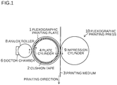
- Figure 1 shows an example of a configuration of a main section of a flexographic printing press 10.
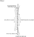
- Figure 2 is an enlarged view of a contact portion between a flexographic printing plate 1 and a printing medium 3 during printing.
- the flexographic printing press (printing unit) 10 includes the flexographic printing plate 1, a plate cylinder 4 to which the flexographic printing plate 1 is attached through a cushion tape 2 such as a double-sided tape, an anilox roller 8 to which ink is supplied by a doctor chamber 6, and an impression cylinder 9 that is provided so as to face the plate cylinder 4.
- Ink is transferred from the anilox roller 8 to an apex (printing face) of a relief 50 of the flexographic printing plate 1. Then, while the printing medium 3 passes through a nip between the plate cylinder 4 to which the flexographic printing plate 1 is attached and the impression cylinder 9, the flexographic printing plate 1 (the apex of the relief 50) is pressed on the printing medium 3 to allow ink attached to the apex of the relief of the flexographic printing plate 1 to be transferred to the printing medium 3, so that a desired image is printed and formed on the printing medium 3.
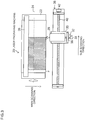
- Figure 3 is a plan view showing an example of a laser engraving machine 20 that forms the relief 50 on the flexographic printing plate 1.
- the laser engraving machine 20 includes a drum 22, and an exposure head 28 for applying exposure engraving to a flexographic plate (printing plate) F held on the drum 22.
- the exposure head 28 is mounted on a stage 30 to be movable by a focus position change mechanism 32 and an intermittent feed mechanism 38.
- the focus position change mechanism 32 includes a motor 34 and a ball screw 36 for allowing the exposure head 28 to move back and forth with respect to the drum 22 to which the flexographic plate F is attached.
- the motor 34 and the ball screw 36 control movement of the exposure head 28 in a main scanning direction to adjust a focus position in exposure engraving processing.
- the intermittent feed mechanism 38 includes a ball screw 40, and a sub-scanning motor 42 that rotates the ball screw 40.
- the ball screw 40 and the sub-scanning motor 42 control movement of the exposure head 28 (stage 30) in a sub-scanning direction, so that the exposure head 28 is intermittently fed in a direction of an axis 24 of the drum 22 (the sub-scanning direction).
- the flexographic plate F attached on the drum 22 is held by a chuck member 26 to fix a holding position of the flexographic plate F on the drum 22.
- the position at which the flexographic plate F is held by the chuck member 26 is within an area where the exposure head 28 does not perform exposure.
- the flexographic plate F is irradiated with a laser beam from the exposure head 28 while the drum 22 is rotated, so that the relief 50 desired is formed on a surface of the flexographic plate F.
- the exposure head 28 stage 30 is intermittently fed in the sub-scanning direction, and then laser engraving is applied to a subsequent line.
- Such “feeding of the flexographic plate F in the main scanning direction with rotation of the drum 22" and “intermittent feeding of the exposure head 28 in the sub-scanning direction” are combined with each other to control an exposure scan position.
- intensity of a laser beam based on exposure data (depth data) for each exposure scan position and ON/OFF of the laser beam are controlled so that the relief 50 in a desired shape is formed on the flexographic plate F by the laser engraving.
- the flexographic printing plate 1 to be used in flexographic printing (refer to Figures 1 and 2 ) is formed.
- the flexographic printing plate 1 (particularly the relief 50) is formed of a soft member rich in elasticity to be deformed in accordance with printing pressure.
- an amount of deformation of the relief 50 varies depending on the amplitude of printing pressure applied, so that a printed image formed on the printing medium 3 also varies.
- the printing pressure applied to the flexographic printing plate 1 varies with not only a kind of the relief 50 (such as a white space, a dot, a protruded thin line, a solid fill) at a position of interest, but also by a kind of the relief 50 in the periphery of the position of interest.
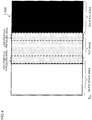
- Figure 4 is a plan view showing an example of a relief formed in a part of the flexographic printing plate 1.
- the relief 50 of the flexographic printing plate 1 shown in Figure 4 is based on 1-bit image data.
- a "white space area” for printing a white space (a left side of Figure 4 ) and a "solid fill area” for printing a solid fill (a right side of Figure 4 ), across a "dot area” where the relief 50 for printing dots with uniform dot density (area ratio) is formed.
- the flexographic printing plate 1 includes such plurality of kinds of area (relief 50), printing pressure applied to each of the areas during printing varies depending on a kind of adjacent area.
- relatively high printing pressure is to be received on a side adjacent to the white space area (refer to a "high printing pressure area” of Figure 4 ), in the dot area
- relatively low printing pressure is received on a side adjacent to the solid fill area (refer to a "low printing pressure area” of Figure 4 ), in the dot area.
- Figure 5 shows an example of a relationship between areas (positions in the direction of an arrow A of Figure 4 ) of the flexographic printing plate 1 shown in Figure 4 and an amount of depression during printing.
- Figure 6 shows an example of a relationship between the areas (positions in the direction of an arrow A of Figure 4 ) of the flexographic printing plate I shown in Figure 4 and printing pressure during printing.
- Figures 5 and 6 show the relationship in a case where the same load is uniformly applied to each of the "white space area", the "dot area”, and the "solid fill area” of the flexographic printing plate 1 shown in Figure 4 .
- the "solid fill area" in the flexographic printing plate 1 is generally brought into contact with the printing medium, so that depression movement of the plate is obstructed during printing.
- the amount of depression itself during printing decreases as compared with the "white space area” and the "dot area” (refer to Figure 5 ).
- pressure per unit area decreases.
- the "dot area" in the flexographic printing plate 1 is partially brought into contact with the printing medium, so that the depression movement of the plate is obstructed during printing.
- the amount of depression during printing decreases as compared with the "white space area”, but increases as compared with the "solid fill area” (refer to Figure 5 ).
- the printing pressure in the "dot area” of the flexographic printing plate 1 during printing is more than that in the "white space area” that is not brought into contact with the printing medium, as well as is more than that in the "solid fill area” with a high contact area ratio with the printing medium.
- the amount of depression and the printing pressure of the flexographic printing plate 1 during printing are affected by characteristics of each of the areas themselves (the relief 50 and contact area), and are further affected by kinds and characteristics of adjacent area.
- Figure 7 is a plan view of the printing medium 3 showing an ideal printed image targeted when ideal printing is performed with the flexographic printing plate 1 shown in Figure 4 .
- Figure 8 is a plan view of the printing medium 3 showing an actual printed image when normal printing is performed with the flexographic printing plate 1 shown in Figure 4 .
- the flexographic printing plate 1 of Figure 8 to be used in printing has uniform plate thickness throughout it, and a printing result on the printing medium 3 of Figure 8 is acquired by assuming that there is no deviation in plate thickness of the flexographic printing plate 1.
- the inventor of the present invention has focused attention on this kind of relationship among distribution of printing pressure, and a printing condition, and has newly found out a technique capable of favorably reproducing an image on a printing medium (printing matter) by determining a relief (engraving shape) of a printing plate in consideration of deformation of a printing plate in accordance with distribution of printing pressure. That is, image data to be printed is analyzed so that distribution of printing pressure to be applied to the flexographic printing plate 1 is estimated, and then an engraving shape is determined (corrected) in consideration of deformation of the flexographic printing plate 1 based on the estimated distribution of printing pressure. As a result, it is possible to accurately print and reproduce a desired image on a printing medium.
- Figure 9 is a block diagram showing a configuration of a flexographic printing system (printing letterpress creation system) 60 in accordance with one embodiment of the present invention.
- the flexographic printing system 60 includes a raster image processor (RIP) device 61 and the printing plate manufacturing apparatus 62, and the RIP device 61 and the printing plate manufacturing apparatus 62 constitute a platemaking device (platemaking method) that forms a relief 50 (relief pattern) based on image data (relief pattern data) on the flexographic plate F (flexographic printing plate 1).
- RIP raster image processor
- the RIP device 61 includes an RIP processing unit 66, a screening processing unit (binary image data creation unit) 68, and an exposure amount data creation unit 70.
- the RIP processing unit 66 expands page description language data, such as portable document format (PDF) data and PostScript (PS; a registered trademark) data, expressing a vector image of a camera-ready copy edited by using a computer or the like, into raster image data.
- PDF portable document format
- PS PostScript
- Each pixel data constituting the raster image data can have 8-bit for each channel in four channels of CMYK, or 256 (0 to 255) gradations, as a gradation value.
- This kind of gradation can be converted into a corresponding dot area ratio (dot density).
- dot density dot density
- the exposure amount data creation unit 70 converts the binary image data into exposure amount data that can be expressed by 16-bit (65536 gradations) or the like. Details of the exposure amount data creation unit 70 will be described later (refer to Figure 10 ).
- the printing plate manufacturing apparatus 62 includes a computer-to-plate (CTP) drawing machine 72 of an engraving type, and the CTP drawing machine 72 includes the laser engraving machine 20 (refer to Figure 3 ).
- CTP drawing machine 72 laser engraving processing by the CTP drawing machine 72 is applied to a flexographic plate (elastic material such as synthetic resin, and rubber) on the basis of exposure amount data supplied from the RIP device 61 (exposure amount data creation unit 70), so that the flexographic printing plate 1 on which the relief 50 reflecting an image to be printed is formed is engraved and manufactured.
- a flexographic plate elastic material such as synthetic resin, and rubber
- the flexographic printing plate 1 manufactured as above is used in the flexographic printing press 10 (refer to Figures 1 and 2 ) provided in a subsequent stage to be used for printing a desired image on the printing medium 3 by transfer printing.
- Figure 10 is a functional block diagram showing an example of a configuration of the exposure amount data creation unit 70 of Figure 9 .
- the exposure amount data creation unit 70 includes a protrusion height data conversion unit 74, an engraving shape data conversion unit 76, an engraving shape data correction unit 78, and an exposure amount data converter 80.
- the protrusion height data conversion unit 74 converts binary image data from the screening processing unit 68 into protrusion height data indicating two-dimensional distribution of height of the relief 50 (height of a protrusion).
- the engraving shape data conversion unit 76 converts the protrusion height data supplied from the protrusion height data conversion unit 74 into engraving shape data (relief pattern data) with higher resolution.
- the engraving shape data is acquired by applying two-dimensional interpolation to the protrusion height data to reproduce a three-dimensional shape of a protrusion, and may be set as depth data indicating a distance in a depth direction of the flexographic plate F.
- the protrusion height data conversion unit 74 and the engraving shape data conversion unit 76 constitute "a relief calculation unit that calculates relief pattern data on the basis of image data".
- the engraving shape data correction unit 78 corrects the engraving shape data (relief pattern data) on the basis of distribution of printing pressure of the flexographic printing plate 1. Details of the engraving shape data correction unit 78 will be described later (refer to Figure 11 ).
- the exposure amount data converter 80 converts the engraving shape data (relief pattern data) corrected by the engraving shape data correction unit 78 into exposure amount data corresponding to an amount of exposure with respect to the flexographic plate F.
- the exposure amount data converter 80 (exposure amount data creation unit 70) is provided as a part of the RIP device 61 (refer to Figure 9 ), but may be provided on a printing plate manufacturing apparatus 62 side.
- the exposure amount data is calculated from correction engraving shape data (relief pattern data), and the printing plate manufacturing apparatus 62 (refer to Figure 9 ) forms the relief 50 on the flexographic plate F (flexographic printing plate 1) on the basis of the exposure amount data calculated.
- Data correction based on distribution of printing pressure of the flexographic printing plate 1 may be performed by a variety of methods, and an amount of data correction calculated on the basis of the distribution of printing pressure may be reflected in the engraving shape data or the exposure amount data. If the amount of data correction is reflected in the engraving shape data, the engraving shape data including the amount of correction is converted into the exposure amount data, whereby exposure processing is performed by using the exposure amount data converted. On the other hand, if the amount of data correction is reflected in the exposure amount data, "the exposure amount data based on the engraving shape data (the amount of data correction is not reflected)" and “the exposure amount data based on the amount of data correction itself' are calculated, whereby “the exposure amount data reflecting the amount of data correction” is calculated from both data pieces. In an example shown in Figure 11 below, a case where the amount of data correction is reflected in the engraving shape data will be described.
- Figure 11 is a functional block diagram showing an example of a configuration of the engraving shape data correction unit 78 of Figure 10 .
- the engraving shape data correction unit 78 includes a printing pressure distribution estimation unit 82, a correction amount calculation unit 84, and a data correction unit 86.
- the printing pressure distribution estimation unit 82 estimates distribution of printing pressure of the flexographic printing plate 1 pressed on the printing medium 3 during printing, on the basis of the engraving shape data (image data).
- the printing pressure distribution estimation unit 82 may estimate the distribution of printing pressure on the basis of not only image data before being converted into the engraving shape data, but also the engraving shape data. In a case where the distribution of printing pressure is calculated more accurately or a relief shape cannot be formed by engraving as shown by a 1-bit image due to characteristics of an engraving device (printing plate manufacturing apparatus 62), it is preferable that the distribution of printing pressure is estimated on the basis of engraving shape data showing a shape to be actually engraved.
- the correction amount calculation unit 84 calculates the amount of correction of the engraving shape data (relief pattern data) on the basis of the distribution of printing pressure estimated by the printing pressure distribution estimation unit 82. A specific example of the calculation of the amount of correction will be described later (refer to Figure 14 ).
- the data correction unit 86 corrects the engraving shape data (relief pattern data) acquired by the engraving shape data conversion unit 76, on the basis of the amount of correction calculated by the correction amount calculation unit 84.
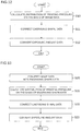
- Figure 12 is a flow chart that shows an outline of a flow of processing in the engraving shape data correction unit 78 and the exposure amount data converter 80, and that shows an example of estimating distribution of printing pressure on the basis of image data before being converted into engraving shape data.
- the printing pressure distribution estimation unit 82 calculates distribution of printing pressure of the flexographic printing plate 1 (S10 of Figure 12 ) on the basis of image data before being converted into engraving shape data (refer to an example of 1-bit image data shown in Figure 18 described later).
- the correction amount calculation unit 84 calculates an amount of correction of the engraving shape data from a calculation result of the distribution of printing pressure, and then the data correction unit 86 corrects the engraving shape data on the basis of the amount of correction calculated (S11).
- the exposure amount data converter 80 converts the engraving shape data corrected in consideration of the distribution of printing pressure into exposure amount data (S12), and then the exposure amount data is transmitted to the printing plate manufacturing apparatus 62(refer to Figure 9 ).
- Figure 13 is a flow chart that shows an outline of a flow of processing in the engraving shape data conversion unit 76, the engraving shape data correction unit 78, and the exposure amount data converter 80, and that shows an example of estimating distribution of printing pressure on the basis of engraving shape data.
- the engraving shape data conversion unit 76 calculates engraving shape data by converting the protrusion height data (image data) (S20 of Figure 13 ).
- the printing pressure distribution estimation unit 82 calculates distribution of printing pressure of the flexographic printing plate 1 on the basis of the engraving shape data acquired (S21). Subsequently, the correction amount calculation unit 84 and the data correction unit 86 calculate the amount of correction of the engraving shape data and correct the engraving shape data on the basis of the distribution of printing pressure (S22), and then the exposure amount data converter 80 (refer to Figure 10 ) converts the engraving shape data corrected into exposure amount data (S23).
- Figure 14 is a flow chart that describes an example of a process of calculating distribution of printing pressure on the basis of image data (engraving shape data) to calculate an amount of correction based on the distribution of printing pressure.
- each processing in the flow of Figure 14 is mainly performed by the correction amount calculation unit 84 of the engraving shape data correction unit 78 (refer to Figure 11 ), another unit may perform a part of the processing if necessary.
- Range affected by distribution of printing pressure of the flexographic printing plate 1 varies with "plate hardness (Shore A) of the flexographic printing plate 1" and "viscoelasticity of the flexographic printing plate 1".
- a size of a region of interest (ROI) that is a "range of distribution of printing pressure (predetermined range) serving as a basis of calculation of the amount of correction of engraving shape data” is determined on the basis of the palate hardness and the viscoelasticity of the flexographic printing plate 1. Accordingly, first, the ROI (range of distribution of printing pressure) is determined on the basis of the plate hardness and the viscoelasticity of the flexographic printing plate 1 that are previously acquired and stored in a memory and the like (S30 of Figure 14 ).
- FIG. 15 shows an example of an image to describe the ROI.
- the ROI is composed of an area of the predetermined range by centering a position of interest (a pixel of interest) in an image, and an amount of correction of relief engraving (engraving shape data) at the position of interest is calculated on the basis of distribution of printing pressure in the ROI.
- the ROI is set for each position in the image, and while the position of interest is sequentially changed in the image, "calculation of the amount of correction of relief engraving at the position of interest based on distribution of printing pressure in the ROI" describe later is performed.
- a size (diameter) of the ROI may be set at a range of from 500 ⁇ m to 3000 ⁇ m.
- a circular ROI by centering a position of interest is set in the example shown in Figure 15
- a size and a shape of the ROI is not particularly limited.
- a ground area ratio (contact area ratio) of the flexographic printing plate 1 with respect to the printing medium 3 in a range of the ROI is calculated (S31 of Figure 14 ).
- a ratio (ground area ratio in vicinity of a pixel of interest) S2 of "area of a relief portion that is brought into contact with the printing medium 3 in a range of the vicinity (hereinafter referred to as also a "vicinity range") during printing” with respect to "area (vicinity area) of the whole of a vicinity range of a pixel of interest (corresponding to a pitch between lines)" is calculated.
- the vicinity range is set so as to be smaller than the range of the ROI.
- the "ground area ratio S1 in an ROI” becomes close to 1 (S1 ⁇ 1)
- a kind of relief at a position of interest (a pixel of interest) is determined, and first, it is determined whether or not the position of interest is an area corresponding to dots (S32 of Figure 14 ). The determination is performed for each of positions of interest (pixels of interest) on the basis of image data (engraving shape data).
- the ratio S above is an index showing a difference in the "ground area ratio S2 of vicinity of a position of interest” with respect to the "ground area ratio S1 in an ROI ".
- the ratio S shows extent of difference in a "ground area ratio of a position of interest” as compared with the "ground area ratio of a reference dot” (or a ground area ratio of a periphery of a position of interest).
- Figure 16 shows an example of a relationship between the ratio S of the "ground area ratio S1 in an ROI” and the “ground area ratio S2 in vicinity of a pixel of interest", and "the amount of correction of engraving shape data for dots".
- a horizontal axis shows the "ratio S” (a ground area ratio of a vicinity range / an ROI) described above
- a vertical axis shows "the amount of correction of engraving shape data”.
- the ratio S of the "ground area ratio S1 in an ROI "and the "ground area ratio S2 in vicinity of a pixel of interest” is 1 if the ground area ratio in an ROI is uniform (refer to the "reference value” in Figure 16 ). Meanwhile, as the "ground area ratio S2 in vicinity of a pixel of interest" becomes more than the "ground area ratio S1 in an ROI", a value of the ratio S becomes more than 1, and as the "ground area ratio S2 in vicinity of a pixel of interest" becomes less than the "ground area ratio S1 in an ROI", the value of the ratio S becomes less than 1.
- the ratio S becomes less than the reference value, and as the ratio S becomes less than the reference value, "the amount of correction of engraving shape data" in consideration of "application of printing pressure less than a reference value" increases, whereby ground area and relief height increase, for example.
- Data showing "the amount of correction of engraving shape data” such as shown in Figure 16 is determined according to a system (the flexographic printing system 60) to be used.
- a system the flexographic printing system 60
- data on “the amount of correction of engraving shape data” with respect to the ratio S of the "ground area ratio S1 in an ROI” and the “ground area ratio S2 in vicinity of a pixel of interest" the data being acquired for each of kinds of relief in advance according to a use system, is stored in a predetermined memory (not shown) or the like to be appropriately read out and used when "the amount of correction of engraving shape data" is calculated.
- a position of interest is a dot
- characteristics of "a relative ratio of a ground area ratio against the amount of correction of engraving shape data" such as shown in Figure 16 , are changed and determined in accordance with a dot area ratio (dot density : dot percent). It is because that if a dot has a high dot percent (particularly, a dot with a dot area ratio of 50 percent or more), deformation of the relief 50 of the flexographic printing plate 1 during printing is relatively small, and if a dot has a low dot percent, the deformation of the relief 50 of the flexographic printing plate 1 during printing is relatively large.
- characteristics of "a relative ratio of a ground area ratio against the amount of correction of engraving shape data" to be a basis of calculation of the amount of correction of engraving shape data in this case characteristics in a case where a position of interest is a protruded thin line are used, and are different from characteristics in a case where a position of interest is a dot (refer to Figure 16 ).
- Characteristics of "a relative ratio of a ground area ratio against the amount of correction of engraving shape data" to be a basis of calculation of the amount of correction of engraving shape data in this case are different from characteristics in a case where a position of interest is a dot (refer to Figure 16 ) and characteristics in a case where a position of interest is a protruded thin line.
- characteristics of "a relative ratio of a ground area ratio against the amount of correction of engraving shape data" to be used at the time of calculation of the amount of correction of engraving shape data described above are determined in accordance with plate hardness and viscoelasticity of the flexographic printing plate 1 (flexographic plate F) to be used, in any of cases where a position of interest is a dot, a protruded thin line, and other than those.
- the data correction unit 86 of the engraving shape data correction unit 78 (refer to Figure 11 ) corrects the engraving shape data on the basis of the amount of correction determined.
- the data correction unit 86 may be provided integrally with the exposure amount data converter 80, "the amount of data correction" acquired on the basis of distribution of printing pressure may not be directly reflected in engraving shape data, but indirectly reflected in exposure amount data.
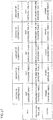
- Figure 17 is a table (conversion table) showing an example of an exposure table to achieve shape correction, in which the "exposure table (an “exposure table 1" to an “exposure table 5" in a “dot", a “protruded thin line", and “other than those")" is associated with “the amount of correction of engraving shape data ("the amount of correction 1" to "the amount of correction 5")" and "a kind of relief of a position of interest (a pixel of interest)".
- exposure amount data corresponding to each "the amount of correction of engraving shape data" determined may be predetermined for each of cases of a “dot", a “protruded thin line", and “other than those” (the "exposure table 1" to the "exposure table 5").
- the exposure amount data converter 80 is able to calculate exposure amount data reflecting the amount of correction for each of cases where a position of interest is a dot, a protruded thin line, a solid fill, and other than those, on the basis of a conversion table such as shown in Figure 17 . Then, the printing plate manufacturing apparatus 62 is able to form an appropriate relief of the flexographic printing plate 1 by engraving on the basis of "the exposure amount data reflecting the amount of correction" calculated in this way.
- the "exposure amount data reflecting the amount of correction” may be calculated by multiplying exposure amount data before correction (exposure amount data derived from engraving shape data before correction) by a numeric value stored in a conversion table such as shown in Figure 17 (a correction reflecting value in an exposure table).
- the engraving shape data and the exposure amount data are corrected as described above to enable relief correction in consideration of distribution of printing pressure.
- Figure 18 shows an example of image data (1-bit image data) before being converted into engraving shape data
- Figure 19 shows an example of engraving shape data that can be acquired from the image data of Figure 18
- Each of Figures 18 and 19 shows a printed image 90 reproduced on the printing medium 3 from image data and engraving shape data.
- distribution of printing pressure of the flexographic printing plate 1 is estimated on the basis of an area ratio of a portion within a predetermined range of the flexographic printing plate 1, the portion being brought into contact with the printing medium 3, the distribution may be estimated on the basis of "image data before being converted into engraving shape data", such as shown in Figure 18 , or on the basis of "engraving shape data", such as shown in Figure 19 .
- Each of Figures 20 and 21 shows an example of "engraving shape data after correction” that can be acquired by correcting the engraving shape data shown in Figure 19 on the basis of distribution of printing pressure.
- each of Figures 20 and 21 shows the printed image 90 reproduced on the printing medium 3 by normal flexographic printing (transfer printing) on the basis of "engraving shape data after correction” by neglecting influence of distribution of printing pressure in the periphery of a position of interest.
- engraving shape data is corrected so that the printed image 90 is expanded as a whole
- the "engraving shape data” is corrected so that the printed image 90 is reduced in size as a whole.
- engraving shape data is corrected to "engraving shape data that allows the printed image 90 to be expanded", such as shown in Figure 20 , to enable the printed image 90 same as that in a case where normal printing pressure is applied to be reproduced on the printing medium 3 as a result, even if applied printing pressure is smaller than normal.
- the engraving shape data is corrected to "engraving shape data that allows the printed image 90 to be reduced in size", such as shown in Figure 21 , to enable the printed image 90 same as that in a case where normal printing pressure is applied to be reproduced on the printing medium 3 as a result, even if applied printing pressure is larger than normal.
- Figure 22 is a perspective view that shows an appearance of an example of the relief 50 formed in a part of the flexographic printing plate 1, and that shows an example of the relief 50 (protrusions 51) created on the flexographic printing plate 1 by engraving on the basis of engraving shape data to which correction in consideration of distribution of printing pressure is not applied.
- Figure 23 is a perspective view that shows an appearance of an example of the relief 50 formed in a part of the flexographic printing plate 1, and that shows an example of the relief 50 (protrusions 51) created on the flexographic printing plate 1 by engraving on the basis of engraving shape data to which correction in consideration of distribution of printing pressure is applied.
- a relief pattern formed on the flexographic printing plate 1 includes the plurality of protrusions 51, each of which has a base, and a tip that is provided on the base to be pressed on the printing medium 3.
- height there are listed height (refer to "T A " of Figure 22 ) of each of the protrusions 51, and a shape of the tip of each of the protrusions 51, to be brought into contact with the printing medium 3 (refer to a diameter "D A " of Figure 22 ), as an element that significantly affects quality of the printed image 90 reproduced on the printing medium 3.
- the engraving shape data includes height data and shape data on the plurality of protrusions 51 included in the relief pattern, and that the amount of correction of engraving shape data based on distribution of printing pressure relates to at least any one of the height data and shape data on the protrusions 51.
- the shape data on the protrusions 51 includes at least shape data on the tip, and that the shape data on the tip includes data on a portion (face) of the tip that is brought into contact with a printing medium during printing.
- the height data on the plurality of protrusions relates to at least any one of tip height, base height, entire height of the tip and base, and particularly to the entire height and the tip height.
- Figure 24 is an external view of the protrusions 51 to describe an example of correcting an engraving shape (tip shape) of a small dot in dots in accordance with distribution of printing pressure, and includes: a portion (a) that shows the protrusion 51 in a case where printing pressure more than normal is applied; a portion (b) that shows the protrusion 51 in a case where normal printing pressure is applied; and a portion (c) that shows the protrusion 51 in a case where printing pressure less than normal is applied.
- Each of the protrusions 51 includes a base 52 in a truncated conical shape, and a tip 53 in a cylindrical shape provided on the base 52, the tip 53 having a cross-sectional diameter that is the same as that of a top end of the base 52.
- the "shape data on the plurality of protrusions 51 in the engraving shape data includes at least the shape data on the tip 53, and the "shape data on the tip 53" includes data on a portion of the tip 53 that is brought into contact with the printing medium 3 during printing, and then the shape (diameter) of the tip 53 of the protrusion 51 is corrected and adjusted in accordance with distribution of printing pressure.
- a diameter of the "portion (ground portion) that is brought into contact with the printing medium 3" of the tip 53 of the protrusion 51 is also set at a normal size (refer to "D2" in the portion (b) of Figure 24 ).
- the diameter of the tip 53 of the protrusion 51 is reduced as compared with that at the time of normal printing pressure (the portion (b) of Figure 24 ) to reduce cross-sectional area of the tip (refer to "D1" in the portion (a) of Figure 24 ). Accordingly, it is possible to perform prediction correction for reducing "expansion of the ground portion and the printed image 90" that is may be caused by deformation of the protrusion 51 (tip 53).
- the diameter of the tip 53 of the protrusion 51 is increased as compared with that at the time of normal printing pressure (the portion (b) of Figure 24 ) to increase the cross-sectional area of the tip (refer to "D3" in the portion (c) of Figure 24 ). Accordingly, it is possible to perform prediction correction for reducing influence of "reduction of the ground portion and the printed image 90 in size" that may be caused by lack of deformation of the protrusion 51 (tip 53) due to small amplitude of printing pressure.
- Figure 25 is an external view of the protrusions 51 (relief 50) to describe an example of correcting an engraving shape (protrusion height) of a small dot in dots in accordance with distribution of printing pressure, and includes: a portion (a) that shows the protrusion 51 in a case where printing pressure more than normal is applied; a portion (b) that shows the protrusion 51 in a case where normal printing pressure is applied; and a portion (c) that shows the protrusion 51 in a case where printing pressure less than normal is applied.
- the "diameter of the tip 53 of the protrusion 51 (relief 50)" is adjusted to perform correction of engraving shape data based on distribution of printing pressure
- "height of the protrusion 51” may be adjusted (to be low layer thickness or high layer thickness) to perform such the correction. That is, it is possible to prevent unintended deformation of the protrusion 51 during printing by adjusting height of a ground portion of the tip 53 of the protrusion 51 to adjust the amplitude of printing pressure applied at a position of interest.
- the adjustment of the "height of protrusion 51" described here means that relative relief height in a relief forming area of the flexographic printing plate 1 is adjusted, and serves as adjustment of a relative position (relative height) with respect to a position of the apex of relief (height) in an area (refer to the "solid fill area” of Figure 4 ) for printing a solid fill portion, for example.
- a ground face (minimum ground face) of the relief 50 (protrusions 51) to be used in printing of a dot with a minimum diameter may be limited. Even in such a case, it is possible to reduce a small dot diameter of printing by adjusting the "height of the protrusion 51" to control a relative distance with respect to the printing medium 3.
- the "height of the protrusion 51" in the tip 53 of the protrusion 51 is also set at a normal height (refer to "T2" in the portion (b) of Figure 25 ).
- the "height of the protrusions 51 is reduced (refer to "T1" in the portion (a) of Figure 25 ) as compared with that at the time of normal printing pressure (the portion (b) of Figure 25 ). Accordingly, it is possible to perform prediction correction for reducing "expansion of the ground portion and the printed image 90" that may be caused by deformation of the protrusion 51 (tip 53).
- the "height of the protrusions 51" is increased (refer to "T3" in the portion (c) of Figure 25 ) as compared with that at the time of normal printing pressure (the portion (b) of Figure 25 ). Accordingly, it is possible to perform prediction correction for reducing influence of "reduction of the ground portion and the printed image 90 in size" that may be caused by lack of deformation of the protrusion 51 (tip 53) due to small amplitude of printing pressure.
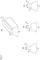
- Figure 26 is an external view of the protrusions 51 (relief 50) to describe an example of correcting an engraving shape (protrusion tip volume) of a small dot in dots in accordance with distribution of printing pressure, and includes: a portion (a) that shows the protrusion 51 in a case where printing pressure more than normal is applied; a portion (b) that shows the protrusion 51 in a case where normal printing pressure is applied; and a portion (c) that shows the protrusion 51 in a case where printing pressure less than normal is applied.
- the engraving shape data may be corrected on the basis of the distribution of printing pressure from a three-dimensional viewpoint. That is, it is preferable that the engraving shape data directly or indirectly includes volume data on the plurality of protrusions 51 included in a relief pattern, and that the amount of correction of engraving shape data based on distribution of printing pressure relates to the volume data.
- volume data on the protrusions 51 may be indirect “volume data” shown by data on a cross-sectional shape (such as a cross-sectional diameter) of each of the protrusions 51 (base 52 and tip 53) and height data on each of the protrusions 51.
- each of the protrusions 51 includes the base 52 in a truncated conical shape that is provided integrally with the tip 53 in a truncated conical shape so that a bottom of the tip 53 is positioned at an apex of the base 52, and a cross-sectional diameter of the apex of the base 52 does not coincide with a cross-sectional diameter of the bottom of the tip 53. Then, there is a relationship as follows: "cross-sectional diameter of the apex of the base 52" > “cross-sectional diameter of the bottom of the tip 53". In this kind of structure, it is possible to control a small dot diameter of printing by adjusting the "volume of the tip 53 of the protrusion 51 ".
- a diameter and height of the tip 53 is determined so that the volume of the tip 53 of the protrusion 51 also becomes a normal size (refer to "D2" and "TH2" in the portion (b) of Figure 26 ).
- the diameter and height of the tip 53 is determined so that the volume of the tip 53 of the protrusion 51 is reduced (refer to "D1" and "TH1" in the portion (a) of Figure 26 ) as compared with that at the time of normal printing pressure (the portion (b) of Figure 26 ). Accordingly, it is possible to perform prediction correction for reducing "expansion of the ground portion and the printed image 90" that may be caused by deformation of the protrusion 51 (tip 53).
- the diameter and height of the tip 53 is determined so that the volume of the tip 53 of the protrusion 51 is increased (refer to "D3" and "TH3" in the portion (c) of Figure 26 ) as compared with that at the time of normal printing pressure (the portion (b) of Figure 26 ). Accordingly, it is possible to perform prediction correction for reducing influence of "reduction of the ground portion and the printed image 90 in size" that may be caused by lack of deformation of the protrusion 51 (tip 53) due to small amplitude of printing pressure.
- Volume of the base 52 may be adjusted in addition to the tip 53 of the protrusion 51 (or instead of the tip 53 of the protrusion 51). That is, in order to reduce the influence from the periphery on printing pressure, a diameter and height of the base 52 may be determined so that the volume of the base 52 decreases if printing pressure more than normal is applied, and so that the volume of the base 52 increases if the printing pressure less than normal is applied (refer to "DB1" to "DB3", and "TH1" to “TH3", in portions (a) to (c) of Figure 26 ). However, since the volume of the tip 53 usually exerts more influence on printing pressure than does the volume of the base 52, it is better to control the volume (a diameter and height) of the tip 53 on a priority basis in many cases.
- an engraving shape (engraving shape data) of the relief 50 (protrusions 51) for dots of the flexographic printing plate 1 may be adjusted by a technique other than the above, and in combination with the techniques shown in Figures 24 to 26 described above, a diameter and height of the tip 53 of the protrusion 51, a diameter and height of the base 52, a size ratio (volume ratio) between the tip 53 and the base 52, and the like, may be appropriately adjusted.
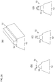
- Figure 27 is an external view of the protrusions 51 to describe an example of correcting a relief engraving shape (tip shape) for printing of a protruded thin line in accordance with distribution of printing pressure, and includes: a portion (a) that is a perspective view of the protrusion 51 for printing of a protruded thin line; a portion (b) that is a cross-sectional view of the protrusion 51 in a case where printing pressure more than normal is applied; a portion (c) that is a cross-sectional view of the protrusion 51 in a case where normal printing pressure is applied; and a portion (d) that is a cross-sectional view of the protrusion 51 in a case where printing pressure less than normal is applied.
- the protrusion 51 for printing of a protruded thin line of the present example includes the base 52 and the tip 53 provided on a top face of the base 52.
- the base 52 has a quadrangular prism shape with a side face in a trapezoidal shape
- the tip 53 has a quadrangular prism shape with a side face in a rectangular shape.
- a size (width) of an "apex (ground portion) that is brought into contact with the printing medium 3" of the tip 53 of the protrusion 51 is also set at a normal size (refer to "D2" in the portion (c) of Figure 27 ).
- the size (width) of the tip 53 of the protrusion 51 is reduced as compared with that at the time of normal printing pressure (the portion (c) of Figure 27 ) to reduce cross-sectional area of the tip (refer to "D1" in the portion (b) of Figure 27 ). Accordingly, it is possible to perform prediction correction for reducing "expansion of the ground portion and the printed image 90" that may be caused by deformation of the protrusion 51 (tip 53).
- the size (width) of the tip 53 of the protrusion 51 is increased as compared with that at the time of normal printing pressure (the portion (c) of Figure 27 ) to increase the cross-sectional area of the tip (refer to "D3" in the portion (d) of Figure 27 ). Accordingly, it is possible to perform prediction correction for reducing influence of "reduction of the ground portion and the printed image 90 in size" that may be caused by lack of deformation of the protrusion 51 (tip 53) due to small amplitude of printing pressure.
- engraving shape data may be corrected from a three-dimensional viewpoint, so that it is possible to prevent unintended deformation of the protrusion 51 during printing by controlling volume of the protrusion 51 (particularly, volume of the tip 53) to adjust the amplitude of printing pressure applied at a position of interest.
- Figure 28 is an external view of the protrusions 51 (relief 50) to describe an example of correcting a relief engraving shape (tip volume) for printing of a protruded thin line in accordance with distribution of printing pressure, and includes: a portion (a) that is a perspective view that shows an appearance of the protrusion 51 for printing of a protruded thin line; a portion (b) that is a cross-sectional view of the protrusion 51 in a case where printing pressure more than normal is applied; a portion (c) that is a cross-sectional view of the protrusion 51 in a case where normal printing pressure is applied; and a portion (d) that is a cross-sectional view of the protrusion 51 in a case where printing pressure less than normal is applied.
- the base 52 of the protrusion 51 for printing of a protruded thin line of the present example has a quadrangular prism shape with a side face in a trapezoidal shape as with the protrusions 51 of Figure 27 , and the tip 53 also has a quadrangular prism shape with a side face in a trapezoidal shape.
- a size (width) of an "apex (ground portion) that is brought into contact with the printing medium 3" of the tip 53 of the protrusion 51 is also set at a normal size (refer to "D2" in the portion (c) of Figure 28 ) so that volume of the tip 53 of the protrusion 51 also becomes normal.
- a size (width) of a ground portion that is brought into contact with the printing medium 3, of the tip 53 is determined so that the volume of the tip 53 of the protrusion 51 is reduced (refer to "D1" in the portion (b) of Figure 28 ) as compared with that at the time of normal printing pressure (the portion (c) of Figure 27 ). Accordingly, it is possible to perform prediction correction for reducing "expansion of the ground portion and the printed image 90" that may be caused by deformation of the protrusion 51 (tip 53).
- a size (width) of the ground portion that is brought into contact with the printing medium 3, of the tip 53 is determined so that the volume of the tip 53 of the protrusion 51 is increased (refer to "D3" in the portion (d) of Figure 27 ) as compared with that at the time of normal printing pressure (the portion (c) of Figure 27 ). Accordingly, it is possible to perform prediction correction for reducing influence of "reduction of the ground portion and the printed image 90 in size" that may be caused by lack of deformation of the protrusion 51 (tip 53) due to small amplitude of printing pressure.
- an engraving shape (engraving shape data) of the relief 50 (protrusions 51) for a protruded thin line of the flexographic printing plate 1 may be adjusted by a technique other than the above, and in combination with the techniques shown in Figures 27 to 28 described above, a width and height of the tip 53 of the protrusion 51, a width and height of the base 52, a size ratio (volume ratio) between the tip 53 and the base 52, and the like, may be appropriately adjusted.
- flexographic printing plate 1 ... flexographic printing plate, 2 ... cushion tape, 3 ... printing medium, 4 ... plate cylinder, 6 ... doctor chamber, 8 ... anilox roller, 9 ... impression cylinder, 10 ... flexographic printing press, 20 ... laser engraving machine, 22 ... drum, 24 ... axis, 26 ... chuck member, 28 ... exposure head, 30 ... stage, 32 ... focus position change mechanism, 34... motor, 36 ... ball screw, 38 ... intermittent feed mechanism, 40 ... ball screw, 42 ... sub-scanning motor, 50 ... relief, 51 ... protrusion, 52 ... base, 53 ... tip, 60 ... flexographic printing system, 61 ... RIP device, 62 ... printing plate manufacturing apparatus, 66 ...
- RIP processing unit 68 ... screening processing unit, 70 ... exposure amount data creation unit, 72 ... CTP drawing machine, 74 ... protrusion height data conversion unit, 76 ... engraving shape data conversion unit, 78 ... engraving shape data correction unit, 80 ... exposure amount data converter, 82 ... printing pressure distribution estimation unit, 84 ... correction amount calculation unit, 86 ... data correction unit, 90 ... printed image.
Landscapes
- Engineering & Computer Science (AREA)
- Physics & Mathematics (AREA)
- Manufacturing & Machinery (AREA)
- Optics & Photonics (AREA)
- Plasma & Fusion (AREA)
- Human Computer Interaction (AREA)
- General Physics & Mathematics (AREA)
- Automation & Control Theory (AREA)
- Manufacture Or Reproduction Of Printing Formes (AREA)
- Printing Plates And Materials Therefor (AREA)
Claims (10)
- Procédé de réalisation de plaque destiné à former un relief sur la base de données de motif de relief dans une plaque d'impression à presser sur un support d'impression, le procédé de réalisation de plaque comprenant les étapes consistant à :calculer des données de motif de relief sur la base de données d'image ;estimer la distribution de pression d'impression sur une plaque d'impression pressée sur un support d'impression sur la base des données d'image ;calculer une quantité de correction de données de motif de relief sur la base de la distribution de pression d'impression, etcorriger les données de motif de relief sur la base de la quantité de correction.
- Procédé de réalisation de plaque selon la revendication 1, dans lequel la distribution de la pression d'impression est estimée sur la base d'un rapport d'aire d'une portion avec laquelle le support d'impression doit être amené en contact dans les limites d'une portée prescrite de la plaque d'impression.
- Procédé de réalisation de plaque selon la revendication 1 ou 2, dans lequel le relief inclut une pluralité de saillies, et les données de motif de relief incluent des données de hauteur et des données de forme de la pluralité de saillies, et dans lequel la quantité de correction des données de motif de relief concerne au moins un type quelconque de données parmi les données de hauteur et les données de forme de la pluralité de saillies.
- Procédé de réalisation de plaque selon la revendication 3, dans lequel chacune de la pluralité de saillies inclut une base et une pointe prévue sur la base, sur laquelle un support d'impression est pressé, et dans lequel les données de forme de la pluralité de saillies concernent au moins des données de forme de la pointe.
- Procédé de réalisation de plaque selon la revendication 4, dans lequel les données de forme de la pointe de chacune de la pluralité de saillie incluent des données sur une portion de la pointe qui doit être amenée en contact avec le support d'impression lors de l'impression.
- Procédé de réalisation de plaque selon l'une quelconque des revendications 3 à 5, dans lequel la pluralité de saillies incluent une base et une pointe prévue sur la base, sur laquelle un support d'impression est pressé, et dans lequel les données de hauteur de la pluralité de saillies concernent au moins un élément quelconque parmi la hauteur de pointe, la hauteur de base, et la hauteur totale de la pointe et de la base.
- Procédé de réalisation de plaque selon la revendication 1 ou 2, dans lequel le relief inclut une pluralité de saillies, et les données de motif de relief incluent des données de volume de la pluralité de saillies, et dans lequel la quantité de correction des données de motif de relief concerne les données de volume de la pluralité des saillies.
- Procédé de réalisation de plaque selon l'une quelconque des revendications 1 à 7, comprenant en outre l'étape de formation du relief sur la plaque d'impression sur la base des données de motif de relief corrigées.
- Dispositif de réalisation de plaque qui forme un relief sur la base de données de motif de relief dans une plaque d'impression à presser sur un support d'impression, le dispositif de réalisation de plaque comprenant :une unité de calcul de relief qui calcule des données de motif de relief sur la base de données d'image ;une unité d'estimation de distribution de pression d'impression qui estime la distribution de la pression d'impression de la plaque d'impression pressée sur le support d'impression sur la base des données d'image ;une unité de calcul de quantité de correction qui calcule une quantité de correction de données de motif de relief sur la base de la distribution de pression d'impression, etune unité de correction de données qui corrige les données de motif de relief sur la base de la quantité de correction.
- Machine à imprimer, comprenant :le dispositif de réalisation de plaque selon la revendication 9, etune unité d'impression qui presse la plaque d'impression dans laquelle un relief est formé par le dispositif de réalisation de plaque sur le support d'impression.
Applications Claiming Priority (2)
| Application Number | Priority Date | Filing Date | Title |
|---|---|---|---|
| JP2013074302A JP5908427B2 (ja) | 2013-03-29 | 2013-03-29 | 製版方法、製版装置及び印刷装置 |
| PCT/JP2014/058438 WO2014157291A1 (fr) | 2013-03-29 | 2014-03-26 | Procédé de réalisation de plaque, dispositif de réalisation de plaque, procédé d'impression et plaque d'impression |
Publications (3)
| Publication Number | Publication Date |
|---|---|
| EP2979866A1 EP2979866A1 (fr) | 2016-02-03 |
| EP2979866A4 EP2979866A4 (fr) | 2016-02-03 |
| EP2979866B1 true EP2979866B1 (fr) | 2017-08-23 |
Family
ID=51624256
Family Applications (1)
| Application Number | Title | Priority Date | Filing Date |
|---|---|---|---|
| EP14775356.0A Not-in-force EP2979866B1 (fr) | 2013-03-29 | 2014-03-26 | Procédé de réalisation de plaque, dispositif de réalisation de plaque, et dispositif d'impression |
Country Status (4)
| Country | Link |
|---|---|
| US (1) | US9487043B2 (fr) |
| EP (1) | EP2979866B1 (fr) |
| JP (1) | JP5908427B2 (fr) |
| WO (1) | WO2014157291A1 (fr) |
Families Citing this family (3)
| Publication number | Priority date | Publication date | Assignee | Title |
|---|---|---|---|---|
| JP6051137B2 (ja) * | 2013-09-30 | 2016-12-27 | 富士フイルム株式会社 | 製版方法、製版装置、印刷装置及び印刷版 |
| CN113500849B (zh) * | 2021-06-16 | 2023-01-17 | 广州爱科琪盛塑料有限公司 | 一种树脂版印刷应用工艺 |
| US11717728B1 (en) * | 2022-02-28 | 2023-08-08 | Acushnet Company | Golf ball having markings spaced from a centerline plane |
Family Cites Families (13)
| Publication number | Priority date | Publication date | Assignee | Title |
|---|---|---|---|---|
| JP2003072292A (ja) | 2001-09-04 | 2003-03-12 | Printing Bureau Ministry Of Finance | 印刷用版面の彫刻方法及び該彫刻方法で彫刻した印刷版 |
| DE60239551D1 (de) | 2002-12-11 | 2011-05-05 | Agfa Graphics Nv | Verfahren zur Erzeugung von 3D-Ausdrucken |
| US7589868B2 (en) | 2002-12-11 | 2009-09-15 | Agfa Graphics Nv | Method and apparatus for creating 3D-prints and a 3-D printing system |
| JP2008230195A (ja) * | 2007-03-23 | 2008-10-02 | Universal Seikan Kk | 凸版、凸版の製造方法及び缶の印刷装置 |
| JP5463649B2 (ja) * | 2008-10-27 | 2014-04-09 | 独立行政法人 国立印刷局 | グラデーション樹脂版面及びグラデーション樹脂版面を用いた印刷物 |
| JP5119191B2 (ja) * | 2009-03-31 | 2013-01-16 | 富士フイルム株式会社 | 印刷版取り付け装置及び印刷版取り付け方法 |
| JP5547543B2 (ja) | 2010-04-20 | 2014-07-16 | 富士フイルム株式会社 | 印刷用凸版 |
| JP5497525B2 (ja) * | 2010-04-20 | 2014-05-21 | 富士フイルム株式会社 | 印刷用凸版作成装置、システム、方法及びプログラム |
| JP5457955B2 (ja) * | 2010-06-28 | 2014-04-02 | 富士フイルム株式会社 | レーザー彫刻用樹脂組成物、レーザー彫刻用レリーフ印刷版原版、レーザー彫刻用レリーフ印刷版原版の製造方法、及び、レリーフ印刷版の製版方法 |
| JP2012074281A (ja) | 2010-09-29 | 2012-04-12 | Dainippon Screen Mfg Co Ltd | 印刷版、印刷装置、及びソフトウェアプログラム |
| JP5496162B2 (ja) * | 2011-09-26 | 2014-05-21 | 富士フイルム株式会社 | 凸版印刷版の製造方法、凸版印刷版作成装置、並びにプログラム |
| JP5908429B2 (ja) | 2013-03-29 | 2016-04-26 | 富士フイルム株式会社 | 製版方法、製版装置及び印刷装置 |
| JP6051137B2 (ja) * | 2013-09-30 | 2016-12-27 | 富士フイルム株式会社 | 製版方法、製版装置、印刷装置及び印刷版 |
-
2013
- 2013-03-29 JP JP2013074302A patent/JP5908427B2/ja not_active Expired - Fee Related
-
2014
- 2014-03-26 EP EP14775356.0A patent/EP2979866B1/fr not_active Not-in-force
- 2014-03-26 WO PCT/JP2014/058438 patent/WO2014157291A1/fr not_active Ceased
-
2015
- 2015-09-22 US US14/861,808 patent/US9487043B2/en not_active Expired - Fee Related
Also Published As
| Publication number | Publication date |
|---|---|
| US9487043B2 (en) | 2016-11-08 |
| JP2014198388A (ja) | 2014-10-23 |
| JP5908427B2 (ja) | 2016-04-26 |
| US20160009115A1 (en) | 2016-01-14 |
| WO2014157291A1 (fr) | 2014-10-02 |
| EP2979866A1 (fr) | 2016-02-03 |
| EP2979866A4 (fr) | 2016-02-03 |
Similar Documents
| Publication | Publication Date | Title |
|---|---|---|
| JP5497525B2 (ja) | 印刷用凸版作成装置、システム、方法及びプログラム | |
| US9415578B2 (en) | Platemaking method, platemaking device, printing press, and printing plate | |
| JP5500853B2 (ja) | 凸版印刷版並びに凸版印刷版の製版方法及び装置 | |
| EP1557279B1 (fr) | Plaques en relief, formes initiales de ces plaques et procédés de fabrication de ces plaques et de ces formes initiales | |
| US20110252990A1 (en) | Printing relief plate | |
| US9487043B2 (en) | Platemaking method, platemaking device, printing press, and printing plate | |
| US9421750B2 (en) | Platemaking method, platemaking device, and printing press | |
| EP2414175B1 (fr) | Plaque d'impression en relief, procédé et appareil de fabrication de plaque d'impression | |
| JP6051137B2 (ja) | 製版方法、製版装置、印刷装置及び印刷版 | |
| US7224490B2 (en) | Method of producing a printing plate on a cylindrical printing-plate carrier in a rotary printing press | |
| EP1367812B1 (fr) | Procédé et dispositif permettant l'élimination des raccords dans des données d'images tramées pour l'impression en continue | |
| US7394570B2 (en) | Method and apparatus for eliminating seams in screened image data for repetitive printing | |
| JP5865812B2 (ja) | 印刷用凸版、印刷用凸版作成装置、印刷用凸版作成方法、印刷装置、印刷方法、印圧判定装置、及び、印圧判定方法 | |
| JP2010017953A (ja) | 印刷物作成方法、印刷物作成システムおよび印刷物 |
Legal Events
| Date | Code | Title | Description |
|---|---|---|---|
| PUAI | Public reference made under article 153(3) epc to a published international application that has entered the european phase |
Free format text: ORIGINAL CODE: 0009012 |
|
| 17P | Request for examination filed |
Effective date: 20150922 |
|
| A4 | Supplementary search report drawn up and despatched |
Effective date: 20160107 |
|
| AK | Designated contracting states |
Kind code of ref document: A1 Designated state(s): AL AT BE BG CH CY CZ DE DK EE ES FI FR GB GR HR HU IE IS IT LI LT LU LV MC MK MT NL NO PL PT RO RS SE SI SK SM TR |
|
| AX | Request for extension of the european patent |
Extension state: BA ME |
|
| DAX | Request for extension of the european patent (deleted) | ||
| GRAP | Despatch of communication of intention to grant a patent |
Free format text: ORIGINAL CODE: EPIDOSNIGR1 |
|
| STAA | Information on the status of an ep patent application or granted ep patent |
Free format text: STATUS: GRANT OF PATENT IS INTENDED |
|
| INTG | Intention to grant announced |
Effective date: 20170309 |
|
| GRAS | Grant fee paid |
Free format text: ORIGINAL CODE: EPIDOSNIGR3 |
|
| GRAA | (expected) grant |
Free format text: ORIGINAL CODE: 0009210 |
|
| STAA | Information on the status of an ep patent application or granted ep patent |
Free format text: STATUS: THE PATENT HAS BEEN GRANTED |
|
| AK | Designated contracting states |
Kind code of ref document: B1 Designated state(s): AL AT BE BG CH CY CZ DE DK EE ES FI FR GB GR HR HU IE IS IT LI LT LU LV MC MK MT NL NO PL PT RO RS SE SI SK SM TR |
|
| REG | Reference to a national code |
Ref country code: GB Ref legal event code: FG4D |
|
| REG | Reference to a national code |
Ref country code: CH Ref legal event code: EP |
|
| REG | Reference to a national code |
Ref country code: AT Ref legal event code: REF Ref document number: 920892 Country of ref document: AT Kind code of ref document: T Effective date: 20170915 |
|
| REG | Reference to a national code |
Ref country code: IE Ref legal event code: FG4D |
|
| REG | Reference to a national code |
Ref country code: DE Ref legal event code: R096 Ref document number: 602014013586 Country of ref document: DE |
|
| REG | Reference to a national code |
Ref country code: NL Ref legal event code: MP Effective date: 20170823 |
|
| REG | Reference to a national code |
Ref country code: LT Ref legal event code: MG4D |
|
| REG | Reference to a national code |
Ref country code: AT Ref legal event code: MK05 Ref document number: 920892 Country of ref document: AT Kind code of ref document: T Effective date: 20170823 |
|
| PG25 | Lapsed in a contracting state [announced via postgrant information from national office to epo] |
Ref country code: HR Free format text: LAPSE BECAUSE OF FAILURE TO SUBMIT A TRANSLATION OF THE DESCRIPTION OR TO PAY THE FEE WITHIN THE PRESCRIBED TIME-LIMIT Effective date: 20170823 Ref country code: SE Free format text: LAPSE BECAUSE OF FAILURE TO SUBMIT A TRANSLATION OF THE DESCRIPTION OR TO PAY THE FEE WITHIN THE PRESCRIBED TIME-LIMIT Effective date: 20170823 Ref country code: AT Free format text: LAPSE BECAUSE OF FAILURE TO SUBMIT A TRANSLATION OF THE DESCRIPTION OR TO PAY THE FEE WITHIN THE PRESCRIBED TIME-LIMIT Effective date: 20170823 Ref country code: LT Free format text: LAPSE BECAUSE OF FAILURE TO SUBMIT A TRANSLATION OF THE DESCRIPTION OR TO PAY THE FEE WITHIN THE PRESCRIBED TIME-LIMIT Effective date: 20170823 Ref country code: FI Free format text: LAPSE BECAUSE OF FAILURE TO SUBMIT A TRANSLATION OF THE DESCRIPTION OR TO PAY THE FEE WITHIN THE PRESCRIBED TIME-LIMIT Effective date: 20170823 Ref country code: NL Free format text: LAPSE BECAUSE OF FAILURE TO SUBMIT A TRANSLATION OF THE DESCRIPTION OR TO PAY THE FEE WITHIN THE PRESCRIBED TIME-LIMIT Effective date: 20170823 Ref country code: NO Free format text: LAPSE BECAUSE OF FAILURE TO SUBMIT A TRANSLATION OF THE DESCRIPTION OR TO PAY THE FEE WITHIN THE PRESCRIBED TIME-LIMIT Effective date: 20171123 |
|
| REG | Reference to a national code |
Ref country code: FR Ref legal event code: PLFP Year of fee payment: 5 |
|
| PG25 | Lapsed in a contracting state [announced via postgrant information from national office to epo] |
Ref country code: RS Free format text: LAPSE BECAUSE OF FAILURE TO SUBMIT A TRANSLATION OF THE DESCRIPTION OR TO PAY THE FEE WITHIN THE PRESCRIBED TIME-LIMIT Effective date: 20170823 Ref country code: IS Free format text: LAPSE BECAUSE OF FAILURE TO SUBMIT A TRANSLATION OF THE DESCRIPTION OR TO PAY THE FEE WITHIN THE PRESCRIBED TIME-LIMIT Effective date: 20171223 Ref country code: ES Free format text: LAPSE BECAUSE OF FAILURE TO SUBMIT A TRANSLATION OF THE DESCRIPTION OR TO PAY THE FEE WITHIN THE PRESCRIBED TIME-LIMIT Effective date: 20170823 Ref country code: LV Free format text: LAPSE BECAUSE OF FAILURE TO SUBMIT A TRANSLATION OF THE DESCRIPTION OR TO PAY THE FEE WITHIN THE PRESCRIBED TIME-LIMIT Effective date: 20170823 Ref country code: GR Free format text: LAPSE BECAUSE OF FAILURE TO SUBMIT A TRANSLATION OF THE DESCRIPTION OR TO PAY THE FEE WITHIN THE PRESCRIBED TIME-LIMIT Effective date: 20171124 Ref country code: PL Free format text: LAPSE BECAUSE OF FAILURE TO SUBMIT A TRANSLATION OF THE DESCRIPTION OR TO PAY THE FEE WITHIN THE PRESCRIBED TIME-LIMIT Effective date: 20170823 Ref country code: BG Free format text: LAPSE BECAUSE OF FAILURE TO SUBMIT A TRANSLATION OF THE DESCRIPTION OR TO PAY THE FEE WITHIN THE PRESCRIBED TIME-LIMIT Effective date: 20171123 |
|
| PG25 | Lapsed in a contracting state [announced via postgrant information from national office to epo] |
Ref country code: RO Free format text: LAPSE BECAUSE OF FAILURE TO SUBMIT A TRANSLATION OF THE DESCRIPTION OR TO PAY THE FEE WITHIN THE PRESCRIBED TIME-LIMIT Effective date: 20170823 Ref country code: CZ Free format text: LAPSE BECAUSE OF FAILURE TO SUBMIT A TRANSLATION OF THE DESCRIPTION OR TO PAY THE FEE WITHIN THE PRESCRIBED TIME-LIMIT Effective date: 20170823 Ref country code: DK Free format text: LAPSE BECAUSE OF FAILURE TO SUBMIT A TRANSLATION OF THE DESCRIPTION OR TO PAY THE FEE WITHIN THE PRESCRIBED TIME-LIMIT Effective date: 20170823 |
|
| REG | Reference to a national code |
Ref country code: DE Ref legal event code: R097 Ref document number: 602014013586 Country of ref document: DE |
|
| PG25 | Lapsed in a contracting state [announced via postgrant information from national office to epo] |
Ref country code: SM Free format text: LAPSE BECAUSE OF FAILURE TO SUBMIT A TRANSLATION OF THE DESCRIPTION OR TO PAY THE FEE WITHIN THE PRESCRIBED TIME-LIMIT Effective date: 20170823 Ref country code: EE Free format text: LAPSE BECAUSE OF FAILURE TO SUBMIT A TRANSLATION OF THE DESCRIPTION OR TO PAY THE FEE WITHIN THE PRESCRIBED TIME-LIMIT Effective date: 20170823 Ref country code: IT Free format text: LAPSE BECAUSE OF FAILURE TO SUBMIT A TRANSLATION OF THE DESCRIPTION OR TO PAY THE FEE WITHIN THE PRESCRIBED TIME-LIMIT Effective date: 20170823 Ref country code: SK Free format text: LAPSE BECAUSE OF FAILURE TO SUBMIT A TRANSLATION OF THE DESCRIPTION OR TO PAY THE FEE WITHIN THE PRESCRIBED TIME-LIMIT Effective date: 20170823 |
|
| PLBE | No opposition filed within time limit |
Free format text: ORIGINAL CODE: 0009261 |
|
| STAA | Information on the status of an ep patent application or granted ep patent |
Free format text: STATUS: NO OPPOSITION FILED WITHIN TIME LIMIT |
|
| 26N | No opposition filed |
Effective date: 20180524 |
|
| PG25 | Lapsed in a contracting state [announced via postgrant information from national office to epo] |
Ref country code: SI Free format text: LAPSE BECAUSE OF FAILURE TO SUBMIT A TRANSLATION OF THE DESCRIPTION OR TO PAY THE FEE WITHIN THE PRESCRIBED TIME-LIMIT Effective date: 20170823 |
|
| REG | Reference to a national code |
Ref country code: CH Ref legal event code: PL |
|
| PG25 | Lapsed in a contracting state [announced via postgrant information from national office to epo] |
Ref country code: MC Free format text: LAPSE BECAUSE OF FAILURE TO SUBMIT A TRANSLATION OF THE DESCRIPTION OR TO PAY THE FEE WITHIN THE PRESCRIBED TIME-LIMIT Effective date: 20170823 |
|
| REG | Reference to a national code |
Ref country code: BE Ref legal event code: MM Effective date: 20180331 |
|
| REG | Reference to a national code |
Ref country code: IE Ref legal event code: MM4A |
|
| PG25 | Lapsed in a contracting state [announced via postgrant information from national office to epo] |
Ref country code: LU Free format text: LAPSE BECAUSE OF NON-PAYMENT OF DUE FEES Effective date: 20180326 |
|
| PG25 | Lapsed in a contracting state [announced via postgrant information from national office to epo] |
Ref country code: IE Free format text: LAPSE BECAUSE OF NON-PAYMENT OF DUE FEES Effective date: 20180326 |
|
| PG25 | Lapsed in a contracting state [announced via postgrant information from national office to epo] |
Ref country code: LI Free format text: LAPSE BECAUSE OF NON-PAYMENT OF DUE FEES Effective date: 20180331 Ref country code: BE Free format text: LAPSE BECAUSE OF NON-PAYMENT OF DUE FEES Effective date: 20180331 Ref country code: CH Free format text: LAPSE BECAUSE OF NON-PAYMENT OF DUE FEES Effective date: 20180331 |
|
| PG25 | Lapsed in a contracting state [announced via postgrant information from national office to epo] |
Ref country code: MT Free format text: LAPSE BECAUSE OF NON-PAYMENT OF DUE FEES Effective date: 20180326 |
|
| PG25 | Lapsed in a contracting state [announced via postgrant information from national office to epo] |
Ref country code: TR Free format text: LAPSE BECAUSE OF FAILURE TO SUBMIT A TRANSLATION OF THE DESCRIPTION OR TO PAY THE FEE WITHIN THE PRESCRIBED TIME-LIMIT Effective date: 20170823 |
|
| PG25 | Lapsed in a contracting state [announced via postgrant information from national office to epo] |
Ref country code: PT Free format text: LAPSE BECAUSE OF FAILURE TO SUBMIT A TRANSLATION OF THE DESCRIPTION OR TO PAY THE FEE WITHIN THE PRESCRIBED TIME-LIMIT Effective date: 20170823 |
|
| PG25 | Lapsed in a contracting state [announced via postgrant information from national office to epo] |
Ref country code: CY Free format text: LAPSE BECAUSE OF FAILURE TO SUBMIT A TRANSLATION OF THE DESCRIPTION OR TO PAY THE FEE WITHIN THE PRESCRIBED TIME-LIMIT Effective date: 20170823 Ref country code: HU Free format text: LAPSE BECAUSE OF FAILURE TO SUBMIT A TRANSLATION OF THE DESCRIPTION OR TO PAY THE FEE WITHIN THE PRESCRIBED TIME-LIMIT; INVALID AB INITIO Effective date: 20140326 Ref country code: MK Free format text: LAPSE BECAUSE OF NON-PAYMENT OF DUE FEES Effective date: 20170823 |
|
| PG25 | Lapsed in a contracting state [announced via postgrant information from national office to epo] |
Ref country code: AL Free format text: LAPSE BECAUSE OF FAILURE TO SUBMIT A TRANSLATION OF THE DESCRIPTION OR TO PAY THE FEE WITHIN THE PRESCRIBED TIME-LIMIT Effective date: 20170823 |
|
| PGFP | Annual fee paid to national office [announced via postgrant information from national office to epo] |
Ref country code: FR Payment date: 20230208 Year of fee payment: 10 |
|
| PGFP | Annual fee paid to national office [announced via postgrant information from national office to epo] |
Ref country code: GB Payment date: 20230202 Year of fee payment: 10 Ref country code: DE Payment date: 20230131 Year of fee payment: 10 |
|
| P01 | Opt-out of the competence of the unified patent court (upc) registered |
Effective date: 20230515 |
|
| REG | Reference to a national code |
Ref country code: DE Ref legal event code: R119 Ref document number: 602014013586 Country of ref document: DE |
|
| GBPC | Gb: european patent ceased through non-payment of renewal fee |
Effective date: 20240326 |
|
| PG25 | Lapsed in a contracting state [announced via postgrant information from national office to epo] |
Ref country code: DE Free format text: LAPSE BECAUSE OF NON-PAYMENT OF DUE FEES Effective date: 20241001 |
|
| PG25 | Lapsed in a contracting state [announced via postgrant information from national office to epo] |
Ref country code: GB Free format text: LAPSE BECAUSE OF NON-PAYMENT OF DUE FEES Effective date: 20240326 |
|
| PG25 | Lapsed in a contracting state [announced via postgrant information from national office to epo] |
Ref country code: FR Free format text: LAPSE BECAUSE OF NON-PAYMENT OF DUE FEES Effective date: 20240331 |
|
| PG25 | Lapsed in a contracting state [announced via postgrant information from national office to epo] |
Ref country code: GB Free format text: LAPSE BECAUSE OF NON-PAYMENT OF DUE FEES Effective date: 20240326 Ref country code: FR Free format text: LAPSE BECAUSE OF NON-PAYMENT OF DUE FEES Effective date: 20240331 Ref country code: DE Free format text: LAPSE BECAUSE OF NON-PAYMENT OF DUE FEES Effective date: 20241001 |