EP2979936A1 - Bürstenloser wischermotor - Google Patents
Bürstenloser wischermotor Download PDFInfo
- Publication number
- EP2979936A1 EP2979936A1 EP14774359.5A EP14774359A EP2979936A1 EP 2979936 A1 EP2979936 A1 EP 2979936A1 EP 14774359 A EP14774359 A EP 14774359A EP 2979936 A1 EP2979936 A1 EP 2979936A1
- Authority
- EP
- European Patent Office
- Prior art keywords
- motor
- case
- motor case
- gear
- wiper
- Prior art date
- Legal status (The legal status is an assumption and is not a legal conclusion. Google has not performed a legal analysis and makes no representation as to the accuracy of the status listed.)
- Withdrawn
Links
- 239000004411 aluminium Substances 0.000 claims abstract description 21
- 229910052782 aluminium Inorganic materials 0.000 claims abstract description 21
- XAGFODPZIPBFFR-UHFFFAOYSA-N aluminium Chemical compound [Al] XAGFODPZIPBFFR-UHFFFAOYSA-N 0.000 claims abstract description 21
- 230000007246 mechanism Effects 0.000 claims abstract description 17
- 230000009467 reduction Effects 0.000 abstract description 8
- 230000001629 suppression Effects 0.000 abstract description 4
- 238000007796 conventional method Methods 0.000 abstract description 3
- 238000004519 manufacturing process Methods 0.000 abstract description 3
- 238000000034 method Methods 0.000 description 11
- XEEYBQQBJWHFJM-UHFFFAOYSA-N Iron Chemical compound [Fe] XEEYBQQBJWHFJM-UHFFFAOYSA-N 0.000 description 8
- 239000011521 glass Substances 0.000 description 8
- 239000000463 material Substances 0.000 description 8
- 230000008569 process Effects 0.000 description 7
- 238000012545 processing Methods 0.000 description 5
- 230000005540 biological transmission Effects 0.000 description 4
- 238000001816 cooling Methods 0.000 description 4
- 229910052742 iron Inorganic materials 0.000 description 4
- 230000033001 locomotion Effects 0.000 description 4
- 229910052751 metal Inorganic materials 0.000 description 4
- 239000002184 metal Substances 0.000 description 4
- 229910000831 Steel Inorganic materials 0.000 description 3
- 230000008859 change Effects 0.000 description 3
- 230000000694 effects Effects 0.000 description 3
- 230000006872 improvement Effects 0.000 description 3
- 239000004065 semiconductor Substances 0.000 description 3
- 239000010959 steel Substances 0.000 description 3
- 230000003247 decreasing effect Effects 0.000 description 2
- 238000013461 design Methods 0.000 description 2
- 239000000428 dust Substances 0.000 description 2
- 238000005516 engineering process Methods 0.000 description 2
- 230000017525 heat dissipation Effects 0.000 description 2
- 238000010030 laminating Methods 0.000 description 2
- 229920006324 polyoxymethylene Polymers 0.000 description 2
- 239000011347 resin Substances 0.000 description 2
- 229920005989 resin Polymers 0.000 description 2
- 238000007789 sealing Methods 0.000 description 2
- 238000004804 winding Methods 0.000 description 2
- 229930182556 Polyacetal Natural products 0.000 description 1
- 239000007767 bonding agent Substances 0.000 description 1
- 238000005266 casting Methods 0.000 description 1
- 230000000052 comparative effect Effects 0.000 description 1
- 238000010276 construction Methods 0.000 description 1
- 238000005520 cutting process Methods 0.000 description 1
- 238000004512 die casting Methods 0.000 description 1
- 238000010438 heat treatment Methods 0.000 description 1
- 239000012212 insulator Substances 0.000 description 1
- 239000000696 magnetic material Substances 0.000 description 1
- 238000012544 monitoring process Methods 0.000 description 1
- 238000000465 moulding Methods 0.000 description 1
- 230000000149 penetrating effect Effects 0.000 description 1
- 230000004044 response Effects 0.000 description 1
Images



Classifications
-
- H—ELECTRICITY
- H02—GENERATION; CONVERSION OR DISTRIBUTION OF ELECTRIC POWER
- H02K—DYNAMO-ELECTRIC MACHINES
- H02K7/00—Arrangements for handling mechanical energy structurally associated with dynamo-electric machines, e.g. structural association with mechanical driving motors or auxiliary dynamo-electric machines
- H02K7/10—Structural association with clutches, brakes, gears, pulleys or mechanical starters
- H02K7/116—Structural association with clutches, brakes, gears, pulleys or mechanical starters with gears
-
- B—PERFORMING OPERATIONS; TRANSPORTING
- B60—VEHICLES IN GENERAL
- B60S—SERVICING, CLEANING, REPAIRING, SUPPORTING, LIFTING, OR MANOEUVRING OF VEHICLES, NOT OTHERWISE PROVIDED FOR
- B60S1/00—Cleaning of vehicles
- B60S1/02—Cleaning windscreens, windows or optical devices
- B60S1/04—Wipers or the like, e.g. scrapers
- B60S1/06—Wipers or the like, e.g. scrapers characterised by the drive
- B60S1/16—Means for transmitting drive
- B60S1/166—Means for transmitting drive characterised by the combination of a motor-reduction unit and a mechanism for converting rotary into oscillatory movement
-
- H—ELECTRICITY
- H02—GENERATION; CONVERSION OR DISTRIBUTION OF ELECTRIC POWER
- H02K—DYNAMO-ELECTRIC MACHINES
- H02K11/00—Structural association of dynamo-electric machines with electric components or with devices for shielding, monitoring or protection
- H02K11/30—Structural association with control circuits or drive circuits
- H02K11/33—Drive circuits, e.g. power electronics
-
- H—ELECTRICITY
- H02—GENERATION; CONVERSION OR DISTRIBUTION OF ELECTRIC POWER
- H02K—DYNAMO-ELECTRIC MACHINES
- H02K5/00—Casings; Enclosures; Supports
- H02K5/02—Casings or enclosures characterised by the material thereof
-
- H—ELECTRICITY
- H02—GENERATION; CONVERSION OR DISTRIBUTION OF ELECTRIC POWER
- H02K—DYNAMO-ELECTRIC MACHINES
- H02K5/00—Casings; Enclosures; Supports
- H02K5/04—Casings or enclosures characterised by the shape, form or construction thereof
- H02K5/16—Means for supporting bearings, e.g. insulating supports or means for fitting bearings in the bearing-shields
-
- H—ELECTRICITY
- H02—GENERATION; CONVERSION OR DISTRIBUTION OF ELECTRIC POWER
- H02K—DYNAMO-ELECTRIC MACHINES
- H02K5/00—Casings; Enclosures; Supports
- H02K5/04—Casings or enclosures characterised by the shape, form or construction thereof
- H02K5/18—Casings or enclosures characterised by the shape, form or construction thereof with ribs or fins for improving heat transfer
-
- H—ELECTRICITY
- H02—GENERATION; CONVERSION OR DISTRIBUTION OF ELECTRIC POWER
- H02K—DYNAMO-ELECTRIC MACHINES
- H02K5/00—Casings; Enclosures; Supports
- H02K5/04—Casings or enclosures characterised by the shape, form or construction thereof
- H02K5/22—Auxiliary parts of casings not covered by groups H02K5/06-H02K5/20, e.g. shaped to form connection boxes or terminal boxes
-
- H—ELECTRICITY
- H02—GENERATION; CONVERSION OR DISTRIBUTION OF ELECTRIC POWER
- H02K—DYNAMO-ELECTRIC MACHINES
- H02K7/00—Arrangements for handling mechanical energy structurally associated with dynamo-electric machines, e.g. structural association with mechanical driving motors or auxiliary dynamo-electric machines
- H02K7/10—Structural association with clutches, brakes, gears, pulleys or mechanical starters
- H02K7/116—Structural association with clutches, brakes, gears, pulleys or mechanical starters with gears
- H02K7/1163—Structural association with clutches, brakes, gears, pulleys or mechanical starters with gears where at least two gears have non-parallel axes without having orbital motion
- H02K7/1166—Structural association with clutches, brakes, gears, pulleys or mechanical starters with gears where at least two gears have non-parallel axes without having orbital motion comprising worm and worm-wheel
-
- H—ELECTRICITY
- H02—GENERATION; CONVERSION OR DISTRIBUTION OF ELECTRIC POWER
- H02K—DYNAMO-ELECTRIC MACHINES
- H02K9/00—Arrangements for cooling or ventilating
- H02K9/22—Arrangements for cooling or ventilating by solid heat conducting material embedded in, or arranged in contact with, the stator or rotor, e.g. heat bridges
- H02K9/227—Heat sinks
-
- H—ELECTRICITY
- H02—GENERATION; CONVERSION OR DISTRIBUTION OF ELECTRIC POWER
- H02K—DYNAMO-ELECTRIC MACHINES
- H02K2213/00—Specific aspects, not otherwise provided for and not covered by codes H02K2201/00 - H02K2211/00
- H02K2213/03—Machines characterised by numerical values, ranges, mathematical expressions or similar information
Definitions
- the present invention relates to a brushless wiper motor which drives a wiper member provided on a windshield for swinging.
- a wiper apparatus is mounted on a vehicle such as automotive vehicle to wipe out rainwater, dust, and the like on a windshield.
- the wiper apparatus includes a wiper member provided on the windshield and a wiper motor for driving the wiper member for rotation.
- the wiper motor is driven for rotation with an ON operation of a wiper switch provided in the interior of the vehicle by an operator. Therefore, the wiper member is configured to make a swinging motion on the windshield to wipe out extraneous material.
- a wiper motor (decelerating-mechanism-equipped wiper motor) described in Patent document 1 includes a motor part and a decelerating part.
- the motor part includes a yoke housing made of metal, and a stator having a winding is fixed inside the yoke housing. Furthermore, a rotor is rotatably disposed inside the stator. That is, the motor part of the wiper motor described in Patent document 1 serves as a brushless motor.
- the decelerating part includes a gear housing made of aluminium, a worm portion provided on a rotating shaft of the rotor, and a worm wheel engaged with the worm portion are accommodated in the gear housing.
- the worm portion and the worm wheel collectively form a decelerating mechanism, the decelerating mechanism is configured to decelerate the rotation of the rotating shaft to increase torque, and the torque-increased rotation is outputted from an output shaft fixed to the worm wheel to the outside.
- Patent document 1 Japanese Patent Application Laid-Open Publication No. 2010-093977 ( FIG. 3 )
- the wiper motor is mounted on vehicles of various sizes from light vehicles to large vehicles, small size and light weight are desired to improve its versatility. Also, since various electronic devices are mounted on a vehicle or the like, it is desired to suppress electromagnetic noise to be generated at the time of actuation of the wiper motor as much as possible. Thus, as the wiper motor described in Patent document 1 described above, a brushless motor has been adopted as a motor part.
- An object of the present invention is to provide a brushless wiper motor which can be improved in size and weight, suppressed in electromagnetic noise, and enhanced in heat-resistance strength.
- a brushless wiper motor which drives a wiper member for swinging, comprising: a motor case in which a stationary portion is fixed; a rotary portion rotatably provided in the stationary portion; a gear mechanism which transmits rotation of the rotary portion to the wiper member; and a gear case in which the gear mechanism is accommodated, wherein the motor case and the gear case are made of aluminium.
- the motor case is provided with a shaft-bearing mounting portion on which a shaft-bearing member is mounted, the shaft-bearing member rotatably supports one side of a rotating shaft in an axial direction, the rotating shaft being provided to a shaft center of the rotary portion.
- the gear case is closed with a cover member made of aluminium, wherein a control board for controlling the rotation of the rotary portion is mounted on the gear cover.
- an concave- convex portion which increases a surface area of the motor case is formed on at least one of an inner circumferential surface and an outer circumferential surface of the motor case.
- the motor case in which the stationary portion is fixed, and the gear case in which the gear mechanism is accommodated are made of aluminium, most heat generated from the stationary portion at the time of actuation of the brushless wiper motor can be directly dissipated outside from the motor case. That is, compared with conventional technique, heat transmitted to the motor case can be efficiently dissipated outside, and the motor case does not reach high temperature. Therefore, as a matter of course, reduction in size and weight can be achieved, suppression of electromagnetic noise can be achieved, and heat-resistance strength can be enhanced. Expensive components capable of resisting high temperatures are not required, and reduction in manufacturing cost can be achieved.
- FIG. 1 is a views showing a vehicle-mounted wiper apparatus including a brushless wiper motor according to the present invention
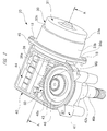
- FIG. 2 is a perspective view showing an outer appearance of the brushless wiper motor (without a gear cover) of FIG. 1
- FIG. 3 is a sectional view (with the gear cover) taken along an A-A line of FIG. 2
- FIG. 4 is a sectional view taken along a B-B line of FIG. 3
- FIGS. 5(a) and 5(b) are graphs respectively showing temperature of coil and temperature of case on the basis of a difference in material (iron/aluminium) of a motor case.
- a vehicle 10 such as automotive vehicle is provided with a front glass (windshield) 11, a wiper apparatus 12 is mounted on a front end portion of the front glass 11 in the vehicle 10, and the wiper apparatus 12 is driven in response to an ON operation on a wiper switch (not depicted) provided in the interior of the vehicle. Therefore, rainwater, dust, and other extraneous material on the front glass 11 are wiped out.
- a wiper switch not depicted
- the wiper apparatus 12 includes a brushless wiper motor 20, a power transmission mechanism 14 for transmitting a swinging motion of the brushless wiper motor 20 to each of pivot shafts 13a and 13b, and a pair of wiper members 15a and 15b whose base ends are respectively fixed to the pivot shafts 13a and 13b, and whose tip ends perform a reciprocating wiping-out operation on the front glass 11 by swinging motions of the pivot shafts 13a and 13b.
- the wiper members 15a and 15b are respectively provided so as to correspond to a driving seat side and a passenger seat side, and the wiper members 15a and 15b are respectively composed of wiper arms 16a and 16b, and wiper blades 17a and 17b attached to the wiper arms 16a and 16b.
- the brushless wiper motor 20 When the brushless wiper motor 20 is driven for rotation, the swinging motion of the brushless wiper motor 20 is transmitted to each of the pivot shafts 13a and 13b via the power transmission mechanism 14, thereby driving each of the pivot shafts 13a and 13b for swinging. In this manner, the driving force of the brushless wiper motor 20 is transmitted to each of the wiper members 15a and 15b, and extraneous materials attached within the wiping ranges 11a and 11b of the front glass 11 are wiped out by the wiper blades 17a and 17b.
- the brushless wiper motor 20 includes a motor part 30 and a gear unit 40, and the motor part 30 and the gear unit 40 are coupled to each other without a gap with a pair of fastening screws 18.
- the motor part 30 includes a motor case 31 made of aluminium.
- the motor case 31 is formed into a bottomed cylindrical shape by deep-drawing process on an aluminium-made plate member, and has a bottom portion 32, a side wall portion 33, and an opening 34.
- a bearing mounting portion (shaft-bearing mounting portion) 32a on which a first bearing (shaft-bearing member) B1 for rotatably supporting one side of a rotating shaft 38 in an axial direction is mounted is formed at a shaft center of the bottom portion 32.
- the bearing mounting portion 32a is formed into a bottomed cylindrical shape.
- the side wall portion 33 includes a small diameter portion 33a and a large diameter portion 33b.
- the small diameter portion 33a is disposed on the same side of the motor case 31 as a bottom portion 32 along an axial direction
- the large diameter portion 33b is disposed on the same side of the motor case 31 as an opening 34 along the axial direction.
- a step portion 33c is formed between the small diameter portion 33a and the large diameter portion 33b, and a flange portion 34a is formed on the same side of the large diameter portion 33b as an opening 34.
- stator 35 in an axial direction abuts on the step portion 33c, and the step portion 33c positions the stator 35 with respect to the axial direction of the motor case 31. Furthermore, the flange portion 34a abuts on a butt flange 45 of a gear case 41 to cause each of the fastening screws 18 to extend so as to penetrate them.
- the stator 35 as a stationary portion is fixed in the motor case 31.
- the stator 35 is formed into a substantially cylindrical shape by laminating steel plates (not shown) which are a plurality of magnetic bodies, and the stator 35 has an outer circumferential portion in contact with the motor case 31 without a gap. Therefore, heat accumulated in the stator 35 can be efficiently transmitted to the motor case 31.
- a resin-made coil bobbin 35a is an insulator, and disposed around the periphery of the stator 35.
- coils 35b (not shown in detail) in "U-phase”, “V-phase”, and “W-phase” (three phases) are wound around the coil bobbin 35a.
- a bus bar unit 36 made of resin is disposed on the other side of the stator 35 in an axial direction.
- the bus bar unit 36 is formed into an annular shape, and a plurality of conductive plates "P" (not shown in detail) formed into a substantially arc shape by press processing on a steel plate are buried in the bus bar unit 36 by insert molding.
- an end of each coil 35b is electrically connected to one end of each conductive plate "P" so as to form a winding of a star connection (Y-connection).
- a method of connecting each coil 35b is not restricted to the star connection as described above, and may be another connecting method such as delta connection (triangular connection).
- three switching elements SW (corresponding to the U-phase, the V-phase, and the W-phase) mounted on a control board 60 housed in the gear cover 50 are electrically connected to the other end of each conductive plate "P". That is, the bus bar unit 36 collects ends of the coils 35b, have a function as a current collector, and configured to electrically connect each coil 35b to the control board 60.
- a rotor 37 as a rotary portion is rotatably provided via a predetermined gap (air gap).
- the rotor 37 is formed into a substantially columnar shape by laminating a plurality of steel plates (not shown) which are magnetic material.
- a plurality of permanent magnets 37a (six poles in this embodiment) each having a substantially arc shape in cross section are attached to a front surface of the rotor 37.
- the permanent magnets 37a are disposed equidistantly (spaced at 60 degrees) so that the poles are alternately arranged along a circumferential direction of the rotor 37.
- a brushless motor having an SPM (Surface Permanent Magnet) structure having the plurality of permanent magnets 37a attached to the front surface of the rotor 37 is adopted in the brushless wiper motor 20.
- the present invention motor is not limited to the brushless motor having the SPM structure, and may be applied to a brushless motor having an IPM (Interior Permanent Magnet) structure with a plurality of permanent magnets buried in the rotor 37.
- the shaft center of the rotor 37 has the rotating shaft 38 penetrating and fixed thereto.
- One side (right side in FIG. 3 ) of the rotating shaft 38 in an axial direction is rotatably supported by the first bearing B1 mounted on the bearing mounting portion 32a of the motor case 32.
- the first bearing B1 is formed of for example a sintered metal subjected to oil bearing process, and brought into contact with both the rotating shaft 38 and the motor case 31. Therefore, heat accumulated in the rotating shaft 38 is efficiently transmitted to the motor case 31 via the first bearing B1.
- the other side (left side in FIG. 3 ) of the rotating shaft 38 extends to the inside of the gear case 41 forming part of the gear portion 40.
- An extended portion of the rotating shaft 38 to the inside of the gear case 41 that is, a portion of the rotating shaft 38 on the other side in the axial direction positioned in the gear case 41, and a substantially center portion thereof are rotatably supported by paired second and third bearings B2 and B3 provided to the gear case 41.
- the second bearing B2 forms part of the gear case 41, that is, the other side of the rotating shaft 38 in the axial direction is rotatably supported directly by the gear case 41. Therefore, heat accumulated in the rotating shaft 38 is efficiently transmitted to the motor case 31.
- a worm 38a forming part of a decelerating mechanism (gear mechanism) SD is integrally provided on the other side of the rotating shaft 38 in the axial direction, and between the bearings B2 and B3.
- a substantially center portion of the worm 38a along an axial direction is smaller in diameter than both end portions of the worm 38a in the axial direction (constricted shape), thereby achieving reduction in diameter of the worm wheel 46, that is, reduction in size and weight of the brushless wiper motor 20, while ensuring engaging strength with a worm wheel 46 (refer to FIG. 2 ).
- the gear portion 40 includes the gear case 41 made of aluminium.
- the gear case 41 is formed into a substantially bath-tub bottomed shape by pouring a molten aluminium material into a mold, and has a bottom portion 42, a side wall portion 43, and an opening 44.
- the butt flange 45 is provided on the same side of the gear case 41 as a motor part 30, faces the flange portion 34a of the motor case 31, and abuts on the flange portion 34a.
- the flange portion 34a and the butt flange 45 are coupled to each other without a gap via the fastening screws 18, and heat accumulated in the stator 35 and others can easily come and go between them. That is, heat inside the brushless wiper motor 20 can be easily dissipated outside.
- the motor case 31 and the gear case 41 are made of aluminium, their linear expansion coefficients are the same as each other. Therefore, even if temperature of use environment is changed, or heat is generated by the brushless wiper motor 20 due to long period of operation, a gap is not formed between the motor case 31 and the gear case 41. That is, sealing performance between them is not decreased due to temperature change.
- the worm wheel 46 is rotatably accommodated in the gear case 41.
- the worm wheel 46 is formed into a substantially disk shape made of resin material such as for example POM (polyacetal) plastic, and gear teeth 46a (not shown in detail) are formed on its outer circumferential portion.
- the worm 38a is engaged with the gear teeth 46a of the worm wheel 46, and the worm wheel 46 and the worm 38a collectively constitute the decelerating mechanism SD accommodated in the gear case 41.
- a base end of an output shaft 46b is fixed to a shaft center of the worm wheel 46, and the output shaft 46b is rotatably supported via a shaft bearing (not shown), to a boss portion 42a integrally provided to the bottom portion 42 of the gear case 41.
- a tip end side of the output shaft 46b extends outside the gear case 41, and the power transmission mechanism 14 (refer to FIG. 1 ) is fixed to a tip end portion of the output shaft 46b.
- the rotation number of the rotating shaft 38 is decelerated by the worm 38a and the worm wheel 46 (decelerating mechanism SD), and the output decelerated so as to have a high torque is transmitted to the power transmission mechanism 14 via the output shaft 46b, thereby driving each of the wiper members 15a and 15b for swinging.
- a sensor magnet MG formed into a substantially disk shape is mounted on the shaft center of the worm wheel 46, and on the opposite side from the output shaft 46b.
- the sensor magnet MG is magnetized in two poles along its circumferential direction. That is, one 180-degree range of the sensor magnet MG is magnetized in the S-pole, and the other 180-degree range is magnetized in the N-pole.
- the sensor magnet MG is used to detect a rotation position of the output shaft 46b with respect to the gear case 41.
- the opening 44 of the gear case 41 is closed with a gear cover (cover member) 50 made of aluminium.
- the gear cover 50 includes a bottom portion 51 and a side wall portion 52, and the bottom portion 51 is provided with a plurality of cooling fins 51a for improving cooling efficiency by widening the surface area of the bottom portion 51.
- the gear case 41 and the gear cover 50 are coupled to each other without a gap via a plurality of fastening screws (not shown), and heat accumulated in the control board 60 and others can easily come and go between them. That is, heat inside the brushless wiper motor 20 can be easily dissipated outside.
- the gear cover 50 and the gear case 41 are made of aluminium, they are the same as each other in linear expansion coefficient. Therefore, even if the temperature of the use environment is changed, or heat are generated in the brushless wiper motor 20 due to long period of operation, a gap is not formed between the gear cover 50 and the gear case 41. That is, sealing performance between them is not decreased with temperature change.
- the control board 60 for controlling the rotation of the rotor 37 is housed in the gear cover 50.
- a vehicle-mounted battery (not shown) and the wiper switch are electrically connected to the control board 60 via an external connector (not shown) on a vehicle 10 which is connected to a connector connecting portion (not shown) provided to the gear cover 50.
- the control board 60 is provided in the gear case 41 and the gear cover 50, and three switching elements SW and another electronic components EP are mounted on the control board 60.
- switching elements SW each of which is a heating element is brought into contact with the inside of the gear cover 50 without a gap. In this manner, heat of each switching element SW can be efficiently dissipated outside.
- each switching element SW is formed with a semiconductor element such as a FET, and more specifically formed with: a positive-side semiconductor element (not shown) that is connected to the positive pole of the vehicle battery, and a negative-side semiconductor element (not shown) that is connected to the negative pole of the vehicle battery.
- a sensor element facing the sensor magnet MG mounted on the shaft center of the worm wheel 46 and a CPU (both not shown) are further mounted on the control board 60.
- a Hall sensor Hall IC which detects a magnetic field
- the sensor element is configured to generate a pulse signal (electrical signal) with a predetermined phase difference in accordance with the rotation of the sensor magnet MG.
- the CPU detects the position of each of the wiper blades 17a and 17b (refer to FIG. 1 ) with respect to the front glass 11, and also controls ON/OFF of each switching element SW to drive the brushless wiper motor 20. In this manner, each of the wiper blades 17a and 17b can be stopped at a predetermined position on the front glass 11, or caused to perform a reverse operation.
- the temperature of the coils is approximately 139 degrees Celsius. This means that, since the motor case 31 is the same in material as the gear case 41, heat dissipation of the brushless wiper motor 20 is markedly improved with the motor case 31 made of aluminium.
- both the motor case 31 in which the stator 35 is fixed, and the gear case 41 in which the decelerating mechanism SD is accommodated are made of aluminium, most heat generated by the stator 35 at the time of actuation of the brushless wiper motor 20 can be directly dissipated outside from the motor case 31. That is, compared with conventional technique, heat transmitted to the motor case 31 can be efficiently dissipated outside, and the motor case 31 does not reach a high temperature. Therefore, as a matter of course, size and weight can be reduced, suppression of electromagnetic noise can be achieved, and heat-resistance strength can be enhanced. Expensive components capable of resisting high temperatures are not required, and reduction in manufacturing cost can be achieved.
- FIGS. 6 (a) -6 (b) are views showing a general outline of a motor case of the second embodiment
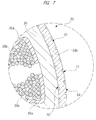
- FIG. 7 is a partially-enlarged sectional view showing details of concave-convex portions of the motor case of FIGS. 6(a)-6(b) .
- the second embodiment is different from the first embodiment in that in order to increase the surface area of the motor case 31, concave-convex portions 70 and 71 are provided to both an inner circumferential surface and an outer circumferential surface of the motor case 31.
- the concave-convex portions 70 and 71 are formed by performing "graining process" on each of the inner circumferential surface and the outer circumferential surface of the large diameter portion 33b in the motor case 31.
- graining process is a processing technology of transferring fine asperities provided on the front surface of a mold (press mold) onto the inner circumferential surface and the outer circumferential surface of the large diameter portion 33b when deep drawing process (press processing) is performed on the motor case 31.
- this processing technique is not restricted to "graining process”, and another processing technique may be adopted as long as the technology can form a concave-convex portion on the front surface of the large diameter portion 33b.
- a plurality of cooling fins as a concave-convex portion may be provided to the outer circumferential surface of the large diameter portion 33b.
- the concave-convex portion 70 formed on the inner circumferential surface of the large diameter portion 33b, the concave-convex portion 70 achieves an "anchor effect" when the stator 35 and the large diameter portion 33b are bonded to each other with a bonding agent (not shown). Therefore, bonding strength between the stator 35 and the large diameter portion 33b can be improved.
- the motor case 31 can be improved in stiffness. Therefore, the motor case 31 can be reduced in weight by making the plate thickness of the motor case 31 thinner.
- the concave-convex portions 70 and 71 are respectively provided to the inner circumferential surface and the outer circumferential surface of the large diameter portion 33b as described above, but they are not restricted to this example. Only the concave-convex portion 71 may be provided to the outer circumferential surface of the large diameter portion 33b. In this case, improvement in heat dissipation capability of the motor case 31 is prioritized in design phase. On the other hand, conversely to this, only the concave-convex portion 70 may be provided to the inner circumferential surface of the large diameter portion 33b. In this case, improvement in bonding strength between the stator 35 and the large diameter portion 33b is prioritized in design phase.
- concave-convex portions 70 and 71 are provided only to the large diameter 33b as described above, but they are not restricted to this example. They may be formed on the small diameter portion 33a, or formed on the bottom portion 32.
- the motor case 31 made of aluminium is formed into a bottomed cylindrical shape by deep drawing process as described above, not restricted to this example.
- the motor case 31 may be formed into a bottomed cylindrical shape by die casting (metal mold casting), or may be formed into a bottomed cylindrical shape by shaving (cutting).
- the brushless wiper motor 20 is applied to a driving source of the wiper apparatus 12 for wiping the front glass 11 of the vehicle 10.
- the present invention is not restricted to this, and can be applied also to a driving source of a rear wiper apparatus of a vehicle or a driving source of a wiper apparatus of a railway vehicle, ship, construction equipment, or the like.
- the brushless wiper motor is used to swing a wiper member forming part of a wiper apparatus to swing so as to wipe a windshield.
Landscapes
- Engineering & Computer Science (AREA)
- Power Engineering (AREA)
- Mechanical Engineering (AREA)
- Microelectronics & Electronic Packaging (AREA)
- Physics & Mathematics (AREA)
- Thermal Sciences (AREA)
- Motor Or Generator Frames (AREA)
- Connection Of Motors, Electrical Generators, Mechanical Devices, And The Like (AREA)
- Permanent Magnet Type Synchronous Machine (AREA)
- Power Steering Mechanism (AREA)
- Brushless Motors (AREA)
Applications Claiming Priority (2)
| Application Number | Priority Date | Filing Date | Title |
|---|---|---|---|
| JP2013072537 | 2013-03-29 | ||
| PCT/JP2014/058655 WO2014157399A1 (ja) | 2013-03-29 | 2014-03-26 | ブラシレスワイパモータ |
Publications (2)
| Publication Number | Publication Date |
|---|---|
| EP2979936A1 true EP2979936A1 (de) | 2016-02-03 |
| EP2979936A4 EP2979936A4 (de) | 2017-01-11 |
Family
ID=51624362
Family Applications (1)
| Application Number | Title | Priority Date | Filing Date |
|---|---|---|---|
| EP14774359.5A Withdrawn EP2979936A4 (de) | 2013-03-29 | 2014-03-26 | Bürstenloser wischermotor |
Country Status (8)
| Country | Link |
|---|---|
| US (1) | US10116186B2 (de) |
| EP (1) | EP2979936A4 (de) |
| JP (1) | JP6324946B2 (de) |
| CN (1) | CN105102280B (de) |
| BR (1) | BR112015024847B1 (de) |
| MX (1) | MX371427B (de) |
| RU (1) | RU2640377C2 (de) |
| WO (1) | WO2014157399A1 (de) |
Cited By (1)
| Publication number | Priority date | Publication date | Assignee | Title |
|---|---|---|---|---|
| EP3628550A1 (de) * | 2018-09-28 | 2020-04-01 | Valeo Autosystemy SP. Z.O.O. | Buerstenloser wischermotor |
Families Citing this family (12)
| Publication number | Priority date | Publication date | Assignee | Title |
|---|---|---|---|---|
| CN105490452B (zh) * | 2014-09-19 | 2020-01-17 | 德昌电机(深圳)有限公司 | 驱动装置 |
| US10533653B2 (en) | 2014-11-10 | 2020-01-14 | Mitsuba Corporation | Motor with speed reduction mechanism |
| JP6495080B2 (ja) * | 2015-04-16 | 2019-04-03 | 株式会社ミツバ | ブラシレスワイパモータ |
| JP6552422B2 (ja) * | 2016-01-19 | 2019-07-31 | 株式会社ミツバ | ブラシレスモータ |
| DE102016212862A1 (de) * | 2016-07-14 | 2018-01-18 | Robert Bosch Gmbh | Leistungseinheit für ein elektrisches Lenksystem |
| JP2018074893A (ja) * | 2016-11-02 | 2018-05-10 | 日本電産株式会社 | ロータ組立体 |
| DE102017121217A1 (de) * | 2017-09-13 | 2019-03-14 | Valeo Systèmes d'Essuyage | Bürstenloser Elektromotor und Verfahren zu dessen Montage |
| JP6681490B2 (ja) * | 2019-03-06 | 2020-04-15 | 株式会社ミツバ | ブラシレスワイパモータおよびワイパ装置 |
| DE202019105035U1 (de) * | 2019-09-12 | 2019-10-11 | Ebm-Papst St. Georgen Gmbh & Co. Kg | Außenläuferrotorvorrichtung mit integrierter Sensorik sowie Verwendung |
| CN114301195B (zh) * | 2021-12-30 | 2024-09-13 | 贵阳万江航空机电有限公司 | 一种无刷电机定子、无刷电机定子的固定方法及无刷电机 |
| JP2024172577A (ja) * | 2023-05-31 | 2024-12-12 | 株式会社ミツバ | モータ装置 |
| CN117411241B (zh) * | 2023-12-13 | 2024-02-13 | 广东敏卓机电股份有限公司 | 一种小型电机 |
Family Cites Families (19)
| Publication number | Priority date | Publication date | Assignee | Title |
|---|---|---|---|---|
| GB280635A (en) * | 1926-08-17 | 1927-11-17 | Henry Chitty | Improvements in or relating to the ventilation and cooling of dynamos, electric motors and similar machines |
| GB344451A (en) * | 1929-12-06 | 1931-03-06 | Lucas Ltd Joseph | Improvements relating to electrically operated wind screen wipers for motor vehicles |
| JPS5852858Y2 (ja) * | 1975-06-11 | 1983-12-01 | 株式会社安川電機 | ガイセンガタデンドウキノレイキヤクソウチ |
| DD142775A1 (de) * | 1979-04-03 | 1980-07-09 | Tischer Hans Juergen | Staenderpaketumkleidung fuer gehaeuselose rotierende elektrische maschine |
| JPH06253496A (ja) * | 1993-02-26 | 1994-09-09 | Showa Alum Corp | モータハウジング |
| JP3685915B2 (ja) * | 1997-11-18 | 2005-08-24 | アスモ株式会社 | モータ装置 |
| FR2789529B1 (fr) * | 1999-02-05 | 2001-06-08 | Valeo Systemes Dessuyage | Perfectionnements aux moteurs electriques a courant continu, notamment pour actionneur de vehicule automobile |
| DE19963158A1 (de) | 1999-12-24 | 2001-06-28 | Valeo Auto Electric Gmbh | Getriebemotor, insbesondere Wischergetriebemotor für ein Fahrzeug |
| CN2522303Y (zh) * | 2001-12-30 | 2002-11-27 | 李源锵 | 雨刷保护器 |
| JP4265902B2 (ja) * | 2002-11-05 | 2009-05-20 | 株式会社ミツバ | モータユニット |
| JP2004320879A (ja) * | 2003-04-15 | 2004-11-11 | Mitsuba Corp | 減速機構付きモータ |
| WO2007055296A1 (ja) * | 2005-11-10 | 2007-05-18 | Nsk Ltd. | 電動式パワーステアリング装置 |
| JP2007181383A (ja) * | 2005-12-28 | 2007-07-12 | Asmo Co Ltd | モータ装置及びワイパ装置 |
| JP2008092642A (ja) * | 2006-09-29 | 2008-04-17 | Mitsuba Corp | モータ装置 |
| JP4843542B2 (ja) * | 2007-03-27 | 2011-12-21 | 株式会社ミツバ | ワイパモータ |
| JP2008252974A (ja) * | 2007-03-29 | 2008-10-16 | Mitsuba Corp | 減速機構付モータ |
| JP5064263B2 (ja) * | 2008-02-27 | 2012-10-31 | 株式会社ミツバ | 減速機構付モータ |
| JP2010093977A (ja) * | 2008-10-09 | 2010-04-22 | Asmo Co Ltd | 減速機構付きモータ |
| EP2736152B1 (de) * | 2011-07-21 | 2020-10-14 | Daikin Industries, Ltd. | Elektromotor und turboverdichter |
-
2014
- 2014-03-26 CN CN201480019095.XA patent/CN105102280B/zh not_active Expired - Fee Related
- 2014-03-26 US US14/780,184 patent/US10116186B2/en active Active
- 2014-03-26 EP EP14774359.5A patent/EP2979936A4/de not_active Withdrawn
- 2014-03-26 JP JP2015508618A patent/JP6324946B2/ja active Active
- 2014-03-26 WO PCT/JP2014/058655 patent/WO2014157399A1/ja not_active Ceased
- 2014-03-26 BR BR112015024847-0A patent/BR112015024847B1/pt not_active IP Right Cessation
- 2014-03-26 MX MX2015013732A patent/MX371427B/es active IP Right Grant
- 2014-03-26 RU RU2015146556A patent/RU2640377C2/ru active
Cited By (1)
| Publication number | Priority date | Publication date | Assignee | Title |
|---|---|---|---|---|
| EP3628550A1 (de) * | 2018-09-28 | 2020-04-01 | Valeo Autosystemy SP. Z.O.O. | Buerstenloser wischermotor |
Also Published As
| Publication number | Publication date |
|---|---|
| CN105102280B (zh) | 2018-01-02 |
| CN105102280A (zh) | 2015-11-25 |
| RU2015146556A (ru) | 2017-05-03 |
| BR112015024847B1 (pt) | 2022-02-08 |
| JPWO2014157399A1 (ja) | 2017-02-16 |
| WO2014157399A1 (ja) | 2014-10-02 |
| MX371427B (es) | 2020-01-24 |
| JP6324946B2 (ja) | 2018-05-16 |
| US20160056686A1 (en) | 2016-02-25 |
| BR112015024847A2 (pt) | 2017-07-18 |
| MX2015013732A (es) | 2016-02-29 |
| RU2640377C2 (ru) | 2017-12-28 |
| US10116186B2 (en) | 2018-10-30 |
| EP2979936A4 (de) | 2017-01-11 |
Similar Documents
| Publication | Publication Date | Title |
|---|---|---|
| US10116186B2 (en) | Brushless wiper motor | |
| JP6793793B2 (ja) | 減速機構付き制御モータ | |
| US9735717B1 (en) | Brushless motor and wiper apparatus | |
| CN106663991B (zh) | 无刷雨刮电机 | |
| JP6634372B2 (ja) | ブラシレスワイパモータ | |
| EP3480925B1 (de) | Scheibenwischermotor | |
| EP3171489B1 (de) | Bürstenloser wischermotor und verfahren zur montage davon | |
| US20160241108A1 (en) | Brushless wiper motor | |
| US10442401B2 (en) | Brushless wiper motor | |
| JP5979924B2 (ja) | ワイパ装置 | |
| EP3431351A1 (de) | Motorsteuerungsvorrichtung und motoreinheit | |
| JP6302638B2 (ja) | ワイパ装置 | |
| JP5350031B2 (ja) | ワイパモータ | |
| JP6640586B2 (ja) | ブラシレスモータ | |
| EP3628550A1 (de) | Buerstenloser wischermotor | |
| JP2017131014A (ja) | ブラシレスモータ | |
| JP2008211921A (ja) | モータ |
Legal Events
| Date | Code | Title | Description |
|---|---|---|---|
| PUAI | Public reference made under article 153(3) epc to a published international application that has entered the european phase |
Free format text: ORIGINAL CODE: 0009012 |
|
| 17P | Request for examination filed |
Effective date: 20150922 |
|
| AK | Designated contracting states |
Kind code of ref document: A1 Designated state(s): AL AT BE BG CH CY CZ DE DK EE ES FI FR GB GR HR HU IE IS IT LI LT LU LV MC MK MT NL NO PL PT RO RS SE SI SK SM TR |
|
| AX | Request for extension of the european patent |
Extension state: BA ME |
|
| DAX | Request for extension of the european patent (deleted) | ||
| A4 | Supplementary search report drawn up and despatched |
Effective date: 20161209 |
|
| RIC1 | Information provided on ipc code assigned before grant |
Ipc: H02K 5/18 20060101ALN20161202BHEP Ipc: H02K 29/08 20060101ALN20161202BHEP Ipc: H02K 5/02 20060101ALI20161202BHEP Ipc: H02K 7/116 20060101AFI20161202BHEP Ipc: B60S 1/16 20060101ALI20161202BHEP Ipc: H02K 9/22 20060101ALI20161202BHEP Ipc: H02K 5/16 20060101ALN20161202BHEP |
|
| 17Q | First examination report despatched |
Effective date: 20170901 |
|
| STAA | Information on the status of an ep patent application or granted ep patent |
Free format text: STATUS: THE APPLICATION IS DEEMED TO BE WITHDRAWN |
|
| 18D | Application deemed to be withdrawn |
Effective date: 20180112 |