EP2980344A1 - Obere radvorrichtung mit prellschutz und doppelrohriger dämpfung - Google Patents
Obere radvorrichtung mit prellschutz und doppelrohriger dämpfung Download PDFInfo
- Publication number
- EP2980344A1 EP2980344A1 EP14785306.3A EP14785306A EP2980344A1 EP 2980344 A1 EP2980344 A1 EP 2980344A1 EP 14785306 A EP14785306 A EP 14785306A EP 2980344 A1 EP2980344 A1 EP 2980344A1
- Authority
- EP
- European Patent Office
- Prior art keywords
- baseplate
- unit
- upper wheel
- pulling
- dampers
- Prior art date
- Legal status (The legal status is an assumption and is not a legal conclusion. Google has not performed a legal analysis and makes no representation as to the accuracy of the status listed.)
- Granted
Links
Images






Classifications
-
- E—FIXED CONSTRUCTIONS
- E05—LOCKS; KEYS; WINDOW OR DOOR FITTINGS; SAFES
- E05F—DEVICES FOR MOVING WINGS INTO OPEN OR CLOSED POSITION; CHECKS FOR WINGS; WING FITTINGS NOT OTHERWISE PROVIDED FOR, CONCERNED WITH THE FUNCTIONING OF THE WING
- E05F1/00—Closers or openers for wings, not otherwise provided for in this subclass
- E05F1/08—Closers or openers for wings, not otherwise provided for in this subclass spring-actuated, e.g. for horizontally sliding wings
- E05F1/16—Closers or openers for wings, not otherwise provided for in this subclass spring-actuated, e.g. for horizontally sliding wings for sliding wings
-
- E—FIXED CONSTRUCTIONS
- E05—LOCKS; KEYS; WINDOW OR DOOR FITTINGS; SAFES
- E05D—HINGES OR SUSPENSION DEVICES FOR DOORS, WINDOWS OR WINGS
- E05D13/00—Accessories for sliding or lifting wings, e.g. pulleys, safety catches
-
- E—FIXED CONSTRUCTIONS
- E05—LOCKS; KEYS; WINDOW OR DOOR FITTINGS; SAFES
- E05D—HINGES OR SUSPENSION DEVICES FOR DOORS, WINDOWS OR WINGS
- E05D15/00—Suspension arrangements for wings
- E05D15/06—Suspension arrangements for wings for wings sliding horizontally more or less in their own plane
- E05D15/0621—Details, e.g. suspension or supporting guides
- E05D15/066—Details, e.g. suspension or supporting guides for wings supported at the bottom
- E05D15/0691—Top guides
-
- E—FIXED CONSTRUCTIONS
- E05—LOCKS; KEYS; WINDOW OR DOOR FITTINGS; SAFES
- E05F—DEVICES FOR MOVING WINGS INTO OPEN OR CLOSED POSITION; CHECKS FOR WINGS; WING FITTINGS NOT OTHERWISE PROVIDED FOR, CONCERNED WITH THE FUNCTIONING OF THE WING
- E05F5/00—Braking devices, e.g. checks; Stops; Buffers
- E05F5/003—Braking devices, e.g. checks; Stops; Buffers for sliding wings
-
- E—FIXED CONSTRUCTIONS
- E05—LOCKS; KEYS; WINDOW OR DOOR FITTINGS; SAFES
- E05F—DEVICES FOR MOVING WINGS INTO OPEN OR CLOSED POSITION; CHECKS FOR WINGS; WING FITTINGS NOT OTHERWISE PROVIDED FOR, CONCERNED WITH THE FUNCTIONING OF THE WING
- E05F5/00—Braking devices, e.g. checks; Stops; Buffers
- E05F5/02—Braking devices, e.g. checks; Stops; Buffers specially for preventing the slamming of swinging wings during final closing movement, e.g. jamb stops
- E05F5/027—Braking devices, e.g. checks; Stops; Buffers specially for preventing the slamming of swinging wings during final closing movement, e.g. jamb stops with closing action
-
- E—FIXED CONSTRUCTIONS
- E05—LOCKS; KEYS; WINDOW OR DOOR FITTINGS; SAFES
- E05Y—INDEXING SCHEME ASSOCIATED WITH SUBCLASSES E05D AND E05F, RELATING TO CONSTRUCTION ELEMENTS, ELECTRIC CONTROL, POWER SUPPLY, POWER SIGNAL OR TRANSMISSION, USER INTERFACES, MOUNTING OR COUPLING, DETAILS, ACCESSORIES, AUXILIARY OPERATIONS NOT OTHERWISE PROVIDED FOR, APPLICATION THEREOF
- E05Y2201/00—Constructional elements; Accessories therefor
- E05Y2201/60—Suspension or transmission members; Accessories therefor
- E05Y2201/622—Suspension or transmission members elements
- E05Y2201/688—Rollers
- E05Y2201/692—Rollers having vertical axes
-
- E—FIXED CONSTRUCTIONS
- E05—LOCKS; KEYS; WINDOW OR DOOR FITTINGS; SAFES
- E05Y—INDEXING SCHEME ASSOCIATED WITH SUBCLASSES E05D AND E05F, RELATING TO CONSTRUCTION ELEMENTS, ELECTRIC CONTROL, POWER SUPPLY, POWER SIGNAL OR TRANSMISSION, USER INTERFACES, MOUNTING OR COUPLING, DETAILS, ACCESSORIES, AUXILIARY OPERATIONS NOT OTHERWISE PROVIDED FOR, APPLICATION THEREOF
- E05Y2600/00—Mounting or coupling arrangements for elements provided for in this subclass
- E05Y2600/10—Adjustable
-
- E—FIXED CONSTRUCTIONS
- E05—LOCKS; KEYS; WINDOW OR DOOR FITTINGS; SAFES
- E05Y—INDEXING SCHEME ASSOCIATED WITH SUBCLASSES E05D AND E05F, RELATING TO CONSTRUCTION ELEMENTS, ELECTRIC CONTROL, POWER SUPPLY, POWER SIGNAL OR TRANSMISSION, USER INTERFACES, MOUNTING OR COUPLING, DETAILS, ACCESSORIES, AUXILIARY OPERATIONS NOT OTHERWISE PROVIDED FOR, APPLICATION THEREOF
- E05Y2600/00—Mounting or coupling arrangements for elements provided for in this subclass
- E05Y2600/10—Adjustable
- E05Y2600/12—Adjustable by manual operation
-
- E—FIXED CONSTRUCTIONS
- E05—LOCKS; KEYS; WINDOW OR DOOR FITTINGS; SAFES
- E05Y—INDEXING SCHEME ASSOCIATED WITH SUBCLASSES E05D AND E05F, RELATING TO CONSTRUCTION ELEMENTS, ELECTRIC CONTROL, POWER SUPPLY, POWER SIGNAL OR TRANSMISSION, USER INTERFACES, MOUNTING OR COUPLING, DETAILS, ACCESSORIES, AUXILIARY OPERATIONS NOT OTHERWISE PROVIDED FOR, APPLICATION THEREOF
- E05Y2600/00—Mounting or coupling arrangements for elements provided for in this subclass
- E05Y2600/40—Mounting location; Visibility of the elements
- E05Y2600/456—Mounting location; Visibility of the elements in or on a suspension member
-
- E—FIXED CONSTRUCTIONS
- E05—LOCKS; KEYS; WINDOW OR DOOR FITTINGS; SAFES
- E05Y—INDEXING SCHEME ASSOCIATED WITH SUBCLASSES E05D AND E05F, RELATING TO CONSTRUCTION ELEMENTS, ELECTRIC CONTROL, POWER SUPPLY, POWER SIGNAL OR TRANSMISSION, USER INTERFACES, MOUNTING OR COUPLING, DETAILS, ACCESSORIES, AUXILIARY OPERATIONS NOT OTHERWISE PROVIDED FOR, APPLICATION THEREOF
- E05Y2600/00—Mounting or coupling arrangements for elements provided for in this subclass
- E05Y2600/60—Mounting or coupling members; Accessories therefor
- E05Y2600/626—Plates or brackets
-
- E—FIXED CONSTRUCTIONS
- E05—LOCKS; KEYS; WINDOW OR DOOR FITTINGS; SAFES
- E05Y—INDEXING SCHEME ASSOCIATED WITH SUBCLASSES E05D AND E05F, RELATING TO CONSTRUCTION ELEMENTS, ELECTRIC CONTROL, POWER SUPPLY, POWER SIGNAL OR TRANSMISSION, USER INTERFACES, MOUNTING OR COUPLING, DETAILS, ACCESSORIES, AUXILIARY OPERATIONS NOT OTHERWISE PROVIDED FOR, APPLICATION THEREOF
- E05Y2800/00—Details, accessories and auxiliary operations not otherwise provided for
- E05Y2800/20—Combinations of elements
- E05Y2800/21—Combinations of elements of identical elements, e.g. of identical compression springs
-
- E—FIXED CONSTRUCTIONS
- E05—LOCKS; KEYS; WINDOW OR DOOR FITTINGS; SAFES
- E05Y—INDEXING SCHEME ASSOCIATED WITH SUBCLASSES E05D AND E05F, RELATING TO CONSTRUCTION ELEMENTS, ELECTRIC CONTROL, POWER SUPPLY, POWER SIGNAL OR TRANSMISSION, USER INTERFACES, MOUNTING OR COUPLING, DETAILS, ACCESSORIES, AUXILIARY OPERATIONS NOT OTHERWISE PROVIDED FOR, APPLICATION THEREOF
- E05Y2800/00—Details, accessories and auxiliary operations not otherwise provided for
- E05Y2800/20—Combinations of elements
- E05Y2800/23—Combinations of elements of elements of different categories
- E05Y2800/24—Combinations of elements of elements of different categories of springs and brakes
-
- E—FIXED CONSTRUCTIONS
- E05—LOCKS; KEYS; WINDOW OR DOOR FITTINGS; SAFES
- E05Y—INDEXING SCHEME ASSOCIATED WITH SUBCLASSES E05D AND E05F, RELATING TO CONSTRUCTION ELEMENTS, ELECTRIC CONTROL, POWER SUPPLY, POWER SIGNAL OR TRANSMISSION, USER INTERFACES, MOUNTING OR COUPLING, DETAILS, ACCESSORIES, AUXILIARY OPERATIONS NOT OTHERWISE PROVIDED FOR, APPLICATION THEREOF
- E05Y2800/00—Details, accessories and auxiliary operations not otherwise provided for
- E05Y2800/40—Physical or chemical protection
- E05Y2800/422—Physical or chemical protection against vibration or noise
-
- E—FIXED CONSTRUCTIONS
- E05—LOCKS; KEYS; WINDOW OR DOOR FITTINGS; SAFES
- E05Y—INDEXING SCHEME ASSOCIATED WITH SUBCLASSES E05D AND E05F, RELATING TO CONSTRUCTION ELEMENTS, ELECTRIC CONTROL, POWER SUPPLY, POWER SIGNAL OR TRANSMISSION, USER INTERFACES, MOUNTING OR COUPLING, DETAILS, ACCESSORIES, AUXILIARY OPERATIONS NOT OTHERWISE PROVIDED FOR, APPLICATION THEREOF
- E05Y2900/00—Application of doors, windows, wings or fittings thereof
- E05Y2900/10—Application of doors, windows, wings or fittings thereof for buildings or parts thereof
- E05Y2900/13—Type of wing
- E05Y2900/132—Doors
-
- F—MECHANICAL ENGINEERING; LIGHTING; HEATING; WEAPONS; BLASTING
- F16—ENGINEERING ELEMENTS AND UNITS; GENERAL MEASURES FOR PRODUCING AND MAINTAINING EFFECTIVE FUNCTIONING OF MACHINES OR INSTALLATIONS; THERMAL INSULATION IN GENERAL
- F16C—SHAFTS; FLEXIBLE SHAFTS; ELEMENTS OR CRANKSHAFT MECHANISMS; ROTARY BODIES OTHER THAN GEARING ELEMENTS; BEARINGS
- F16C29/00—Bearings for parts moving only linearly
- F16C29/04—Ball or roller bearings
Definitions
- the present invention relates to the field of manufacture of hardware accessory for architectural decoration, especially relates to an upper wheel for a sliding door, and more especially relates to an anti-jumping upper wheel device with double dampers.
- damper assemblies used in cupboard doors (sliding doors), dampers in a general damper assembly for a sliding door are used in relative left and right sides and thus rigid assembly requirements is needed; and while usually the damper assembly has only one damper and thus has limited damping force.
- damper assembly has only one damper and thus has limited damping force.
- you want to enhance damping force you need to mount two dampers for a damper assembly in both left and right sides, correspondingly you thus need to mound a pulling sheet respectively for each damper in the track, and therefore a very complicated structure and more rigid assembly requirements are needed.
- the present invention aims to provide an anti-jumping upper wheel assembly with double dampers, which can anti jumping of the door leaf, and whose upper widget is easy to be assembled and is firm, and whose upper widget cooperates well with the damper sliding unit.
- the present invention provides the following technical solution:
- each of both ends on longitudinal direction of said baseplate of pulling unit is cut into three longitudinal branch plates in parallel, and said baseplate of elastic unit of said connecting elastic unit is comprised of three sub-plates which are a left baseplate fixed to said left erect plate, a right baseplate fixed to said right erect plate and a middle baseplate fixed between said left baseplate and said right baseplate.
- said left baseplate is in the same plane with said right baseplate
- said middle baseplate is raised with respect to said left baseplate and said right baseplate in order that said branch plate in the middle can fit to bottom of said middle baseplate and said branch plate at both sides can respectively fit to top of said left baseplate and said right baseplate.
- two raised heads are respectively mounted on said left baseplate and said right baseplate, said raised heads respectively fit to and connect to said connecting holes in two of said three longitudinal perpendicular branch plates at sides, an assembly hole is mounted to said middle baseplate to fit to said connecting hole in one of said three longitudinal perpendicular branch plates in the middle, and a screw goes through said assembly hole and said connecting hole to assemble.
- a vertically upright guiding unit and an internal six angle stud in parallel therewith are fixed on said baseplate of pulling unit, a guiding hole fitting to said guiding unit and a screw hole fitting to said internal six angle stud are correspondingly mounted to said pillar plate of pulling unit, said guiding unit and said internal six angle stud go through said guiding hole and said screw hole respectively, and distance between said pillar plate of pulling unit and said baseplate of pulling unit can be adjusted by rotating said internal six angle stud.
- said lug boss is in cuboid.
- a "+"symbol-shaped groove hole is mounted to said upper wheel cover at the end to which a groove for sliding is mounted, and said anti-jumping roller is assembled in said "+"symbol shaped groove hole.
- damper sliding unit has a plugging hole fitting to said pulling unit, a groove for sliding corresponding to said damper sliding unit is mounted to said upper wheel cover, said plugging hole is positioned in said groove for sliding, and said pulling unit can go through said groove for sliding and plug into said plugging hole.
- an extension spring is mounted in parallel with and between said two dampers, a connecting unit is connected to said damper sliding unit, and said heads of drawbars of said dampers and the corresponding head of said extension spring are connected to said connecting unit.
- said damper sliding unit has a fitting pillar, a guiding groove used for guiding said fitting pillar is mounted to inner surface of said upper wheel cover, said guiding groove has a bent portion at an end, and said bent portion and said damper sliding unit are proper structured in order that said fitting pillar can fit to said bent portion as sliding into said bent portion and can get out as sliding to opposite direction.
- the present invention has the following advantages: special structured pulling unit with double plates is easy to be assembled in the upper track and very firm, in order that the pulling unit can function well and pull the damper sliding unit to move, and wherein the anti-jumping roller can prevent the door leaf from jumping at the time of being open and closed, to ensure the door leaf move smoothly, and the anti-jumping upper wheel device with double dampers is simple and compact in structure and is with low cost.
- special structured pulling unit with double plates is easy to be assembled in the upper track and very firm, in order that the pulling unit can function well and pull the damper sliding unit to move, and wherein the anti-jumping roller can prevent the door leaf from jumping at the time of being open and closed, to ensure the door leaf move smoothly
- the anti-jumping upper wheel device with double dampers is simple and compact in structure and is with low cost.
- Figure 20 and figure 21 show whole views of the anti-jumping upper wheel device with double dampers of an embodiment of the present invention, which is comprised of two parts: an anti-jumping upper wheel assembly with double dampers 10 assembled at top end of the door leaf of a sliding door in use, and a pulling unit 20 assembled in the upper track in use.
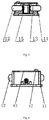
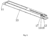
- Figures 1 to 7 show the ant-jump upper wheel assembly with double dampers 10 and its components
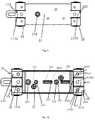
- figures 8 to 13 show the pulling unit
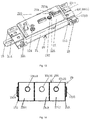
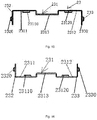
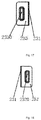
- figures 14 to 19 show the connecting elastic unit 23 of the pulling unit 20.
- Figure 22 shows a diagrammatic view of the anti-jumping upper wheel device with double dampers being assembled to the door leaf A and the upper track B.
- the anti-jumping upper wheel assembly with double dampers 10 is comprised of an upper wheel plate 11, an upper wheel 12 and an upper wheel cover 13 mounted on the upper wheel plate 11, and a damper 14 an end of which is connected to a damper sliding unit 15 is mounted on longitudinal direction in the upper wheel cover 13 on the upper wheel plate 11.
- the upper wheel 12 can fit to and slide along the upper track in which a door leaf is assembled.
- two dampers 14 are mounted on longitudinal direction in parallel in the upper wheel cover 13 on the upper wheel plate 11, the damper sliding unit 15 is connected to ends of drawbars of the two dampers, and damping effect is enhanced because of these two dampers.
- an extension spring 16 which can also be pulled and pushed by the damper sliding unit 15 is mounted in parallel with and between two dampers 14. Damper assembling grooves 133, 134 for two dampers 14 and an extension spring assembling groove 135 for the extension spring 16 are mounted in the upper wheel cover 13.
- the damper sliding unit 15 is connected with a connecting unit 151 which has connecting holes for dampers' drawbars 1510,1511 and a connecting hole for extension spring 1512, ends of the drawbars of two dampers 14 and the corresponding end of the extension spring 16 are respectively connected to the connecting holes for dampers' drawbars 1510,1511 and the connecting hole for extension spring 1512, in order that the dampers 14 and the extension spring 16 can be pulled and pushed by the damper sliding unit 15.
- a groove for sliding 131 is mounted in the upper cover 13 at the position corresponding to the damper sliding unit 15, the groove for sliding 131 is mounted at longitudinal middle position of the upper wheel cover 13 i.e. middle position between two dampers 14, and aligns with position of the extension spring 16.
- damper sliding unit 15 has a plugging hole 150 and a fitting pillar.
- the plugging hole 150 is positioned in the groove for sliding 131, so that the pulling pillar (will be described in the following) of the pulling unit 20 can go through the groove for sliding 131 and plug into the plugging hole 150 to pull the damper sliding unit 15.
- a guiding groove 132 for guiding the fitting pillar is mounted to inner surface of the upper wheel cover 13, the guiding groove 132 has a bent portion 1320 at the last end which fits to the above-mentioned fitting pillar of the damper sliding unit 15, and the bent portion 1320 and the damper sliding unit 15 are proper structured in order that the fitting pillar can be fitted and locked in the bent portion 1320 when it slides into the bent portion 1320 and at which moment the extension spring 16 reaches to its maximum and the damper 14 is "strung", and the fitting pillar can get out of the bent portion 1320 when it is being pushed on reverse direction and at this moment the damper is "unhooked” and acts damping effect.
- the damper sliding unit should have proper structure to satisfy the above mentioned requirements of function and assembly, Chinese patent No.zI201320065103.7 provides a preferred example of the damper sliding unit whose technical solution can be cited in the present invention and will not be described in detail, and the present invention of course can use other equivalent structures.
- An anti-jumping roller 17 is mounted in the upper wheel cover 13, a fixed axle of which is vertical with direction that the door leaf moves (longitudinal direction of the anti-jumping upper wheel assembly with double dampers 10), and the anti-jumping roller rotates around the fixed axle; moreover, an upper part of the anti-jumping roller 17 protrudes out of top face of the upper wheel cover.
- the anti-jumping roller 17 is a general rotatable wheel, and preferably a plastic wheel, the height thereof protruding out of the top face of the upper wheel cover 13 is equal to distance between the top face of upper wheel cover 13 and surface of a pillar plate of pulling unit of the pulling unit 20 which will be described in the following, the anti-jumping roller 17 rotates on the pillar plate of pulling unit along the direction that the door leaf moves and accordingly the door leaf has no space to jump , therefore the door leaf jumping at the time of being opened and closed is avoid, and a very great effect is obtained with applying.
- a "+"symbol shaped groove hole 1310 is mounted to the upper wheel cover in the end to which the groove for sliding 131 is mounted, and the anti-jumping roller 17 is assembled in the "+"symbol shaped groove hole 1310.
- the pulling unit 20 is a pulling unit with double plates, which is comprised of a baseplate of pulling unit 21 and a pillar plate of pulling unit 22 assembled below the baseplate of pulling unit 21; a pulling pillar 221 fitting to the plugging hole 150 of the damper sliding unit 15 is fixed vertically on the face of pillar plate of pulling unit 22.
- the pulling pillar 221 is a very important functional part, and it can be inserted into the plugging hole 150 to pull the damper sliding unit 15 and make the damper 14 "strung", can get out of the plugging hole 150 when moving on after the damper is "strung", and can force the damper sliding unit on reverse direction of sliding to make the damper act damping function.
- Actual length of the pulling pillar 221 is usually not the effective length plugged into the plugging hole 150 because of limit by assemble, but the structure of double plates can make the pillar plate of pulling unit 22 be closer to the top of the door leaf in order to increase the effective length of the pulling pillar while the baseplate of pulling unit 21 is assembled to the top surface of the upper track.
- the pillar plate of pulling unit 22 is comprised of a plastic board and a metal baseplate overlapped both of which are fixed together by a screw marked by 224 in figures from bottom to top and a screw marked by 225 from top to bottom.
- the pillar plate of pulling unit 22 thus moves upward or downward with relative to the baseplate of pulling unit 21, and the effective length of the pulling pillar 221 fixed on the pillar plate of pulling unit 22 will be elongated or shorten in order that it can fit to the damper sliding unit 15 and plug into the plugging hole 150 and therefore can pull the damper sliding unit 15 effectively to work; and whole height of the pulling unit 20 can also be adjusted to fit different assembly width.
- the end 213 on longitudinal direction of the baseplate of pulling unit 21 is cut into three longitudinal branch plates in parallel 2131, 2132, 2133, the end 214 on longitudinal direction of the baseplate of pulling unit 21 is cut into three longitudinal branch plates in parallel 2141, 2142, 2143, and a connecting hole is mounted to each branch plate of each end on longitudinal direction; a connecting elastic unit 23 and a connecting elastic unit 24 are respectively connected to the three longitudinal branch plates in parallel of both ends of the baseplate of pulling unit 21. Since structure of the end 213 on longitudinal direction and the connecting elastic unit thereon are mainly identical with that of the end 214 on longitudinal direction and the connecting elastic unit thereon, thus only take the end 213 on longitudinal direction for example to illustrate the structures next.
- three longitudinal branch plates in parallel 2131, 2132, 2133 of the end 213 on longitudinal direction of the baseplate of pulling unit 21 respectively has a connecting hole a, b, c
- the connecting elastic unit 23 is connected to the three longitudinal branch plates in parallel
- the connecting elastic unit 23 is made of elastic material which is good for assembly in the upper track steadily.
- the connecting elastic unit 23 is comprised of a baseplate of elastic unit 231, and a left erect plate 232 and a right erect plate 233 which are respectively fixed on both ends of the baseplate of elastic unit 231,
- the baseplate of elastic unit 231 has a left baseplate 2311 fixed with the left erect plate232, a right baseplate 2312 fixed with the right erect plate 233, and a middle baseplate 2313 mounted between the left baseplate 2311 and the right baseplate 2312.
- the connecting elastic unit 23 is made in a whole.
- each of the left baseplate 2311, the middle baseplate 2313 and the right baseplate 2312 respectively fit to the branch plates 2131, 2132, 2133 in parallel on longitudinal direction, in order that the connecting elastic unit 23 can be overlapped and connected to the baseplate of pulling unit 21; each of the left baseplate 2311, the middle baseplate 2313 and the right baseplate 2312 has an assembly hole or a raised head fitting to the connecting holes a, b, c of the corresponding branch plate.
- the left baseplate 2311 and the right baseplate 2312 are in the same plane, the middle baseplate 2313 raises from the left baseplate 2311 and the right baseplate 2312, so that the middle branch plate 2132 can fit to bottom of the middle baseplate 2313 and the branch plates 2131, 2133 in both sides can fit to top of the left baseplate 2311 and the right baseplate 2312 as connecting in parallel.
- the left baseplate 2311 and the right baseplate 2312 respectively have raised heads 23110, 23120 which respectively fit to and connect to the connecting holes a, c of two branch plates 2131, 2133 in both sides of the three longitudinal branch plates in parallel;
- the middle baseplate 2313 has an assembly hole 23130 fitting to the connecting hole b of the branch plate 2132 in the middle of the three longitudinal branch plates in parallel, and a screw passes through the assembly hole 23130 and the connecting hole b to assemble.
- the middle baseplate can dent with relative to the left and the right baseplates, so that the branch plate in the middle can fit to top of the middle baseplate and the branch plates in two sides can respectively fit to bottom of the left and the right baseplate when connecting in parallel.
- one of the left, the middle and the right baseplates has an assembly hole to connect with corresponding branch plate by screw and the other two of them has raised heads to connect in the connecting hole of corresponding branch plates; and the like.
- both ends on longitudinal direction of the baseplate of pulling unit can be cut into more than three longitudinal branch plates in parallel in some situations, each of which has a connecting hole; and a connecting elastic unit is overlapped and connected in parallel to the more than three longitudinal branch plates in parallel of each end on longitudinal direction of the baseplate of pulling unit.
- elastic baseplate of the connecting elastic unit has more than three corresponding sub-plates which is same in quantity with the branch plates of corresponding end of the baseplate of pulling unit, and therein at least one sub-plate is raised or dent with relative to other sub-plates so that all the sub-plates are not in the same plane in order to achieve overlapping connection by some sub-plates fitting in top face of corresponding branch plate and other sub-plates fitting in bottom face of corresponding branch plate. Then the raised head as in the above mentioned example wedges in the connecting hole of the branch plate or the screw passes through corresponding connecting hole and assembly hole to assemble.
- a lug boss 2320 and a lug boss 2330 are respectively mounted on outer surfaces of the left erect plate 232 and the right erect plate 233, vertical distance between the outer surface of the lug boss 2320 of the left erect plate and the outer surface of the lug boss 2330 of the right erect plate are identical with vertical width of the upper track.
- both lug bosses are cuboid.
- the pulling unit with double plates 20 are assembled upside down in the upper track with the baseplate of elastic unit 231 pressing against bottom of the upper track, and the lug bosses 2320, 2330 mentioned above respectively press against left and right sides of the upper track so that the pulling unit can be moved easily because of the structure of lug boss in need of adjusting position of the pulling unit 20 in the upper track.
- the pulling pillar 221 of the pulling unit with double plates 20 does not contact the damper sliding unit 15 of the anti-jumping upper wheel assembly with double dampers 10 when the door leaf A is being pulled from side to middle of the door frame, and then when the door leaf A is moved on from middle to the other side of the door frame the damper sliding unit 15 of the upper wheel assembly with double dampers 10 will contact the pulling pillar 221 and pull the pulling unit with double plates 20 toward the side of the door frame until reach it, and the pulling unit with double plates 20 is located voluntarily at this position. Then we can screw the internal six angle stud 212 by six angle screwdriver to press the internal six angle stud 212 against top of the upper track and thus fix the pulling unit with double plates 20.
- the pulling pillar 221 collides with the damper sliding unit 15 and makes the damper sliding unit 15 "unhooked" when the upper wheel assembly with double dampers 10 slides to below of the pulling unit with double plates 20, and at this time the dampers of the upper wheel assembly with double dampers 10 functions to force the door leaf on reverse direction, the door leaf A will thus move smoothly without jumping and collision to reach edge of the door frame safely.
- the anti-jumping upper wheel device with double dampers of the present example are as follows: (i) it is novel in design and is proper structured; (ii) height of the pulling pillar can be adjusted; (iii) it can be assembled easily: because the connecting elastic unit is mounted at both sides of the baseplate of pulling unit of the pulling unit with double plates, which is made of material with high elasticity and which has cuboid lug bosses on the left and the right erect plates, the pulling unit with double plates thus can be assembled in the upper track with the connecting elastic unit pressing against both inner surface of the upper track steadily without falling off, and can also be pulled and pushed to move in the upper track; (iv) position of the pulling unit with double plates can be located voluntarily without manual work because of the improved structure of the baseplate of pulling unit; and (v) the anti-jumping upper wheel with double dampers has function of damping and anti-jumpinging .
Landscapes
- Support Devices For Sliding Doors (AREA)
- Engineering & Computer Science (AREA)
- Vibration Dampers (AREA)
- Mechanical Engineering (AREA)
- General Engineering & Computer Science (AREA)
- Handcart (AREA)
- Braking Arrangements (AREA)
Priority Applications (1)
| Application Number | Priority Date | Filing Date | Title |
|---|---|---|---|
| PL14785306T PL2980344T3 (pl) | 2013-04-15 | 2014-04-08 | Amortyzujące, zapobiegające podskakiwaniu urządzenie górnego koła z podwójną rurą |
Applications Claiming Priority (3)
| Application Number | Priority Date | Filing Date | Title |
|---|---|---|---|
| CN2013201885164U CN203285216U (zh) | 2013-04-15 | 2013-04-15 | 双管阻尼防跳壁柜上轮 |
| CN201320403640.8U CN203531589U (zh) | 2013-07-08 | 2013-07-08 | 改进型双管阻尼防跳壁柜上轮 |
| PCT/CN2014/074903 WO2014169771A1 (zh) | 2013-04-15 | 2014-04-08 | 双管阻尼防跳上轮装置 |
Publications (3)
| Publication Number | Publication Date |
|---|---|
| EP2980344A1 true EP2980344A1 (de) | 2016-02-03 |
| EP2980344A4 EP2980344A4 (de) | 2016-03-23 |
| EP2980344B1 EP2980344B1 (de) | 2017-05-10 |
Family
ID=51730797
Family Applications (1)
| Application Number | Title | Priority Date | Filing Date |
|---|---|---|---|
| EP14785306.3A Active EP2980344B1 (de) | 2013-04-15 | 2014-04-08 | Obere radvorrichtung mit prellschutz und doppelrohriger dämpfung |
Country Status (11)
| Country | Link |
|---|---|
| US (1) | US9834972B2 (de) |
| EP (1) | EP2980344B1 (de) |
| KR (1) | KR101755144B1 (de) |
| BR (1) | BR112015026198B1 (de) |
| CY (1) | CY1119564T1 (de) |
| DK (1) | DK2980344T3 (de) |
| ES (1) | ES2637206T3 (de) |
| IL (1) | IL242010B (de) |
| PL (1) | PL2980344T3 (de) |
| RU (1) | RU2620753C2 (de) |
| WO (1) | WO2014169771A1 (de) |
Cited By (3)
| Publication number | Priority date | Publication date | Assignee | Title |
|---|---|---|---|---|
| EP3070249A1 (de) * | 2015-03-17 | 2016-09-21 | Günther Zimmer | Aktivator einer kombinierten beschleunigungs- und verzögerungsvorrichtung |
| CN106121422A (zh) * | 2016-08-15 | 2016-11-16 | 株洲合力电磁技术有限公司 | 一种防护双扇门 |
| EP3170956A1 (de) * | 2015-11-19 | 2017-05-24 | Adinor, S.L. | Dämpfungssystem für schränke mit schiebetüren |
Families Citing this family (9)
| Publication number | Priority date | Publication date | Assignee | Title |
|---|---|---|---|---|
| ES2542052B2 (es) * | 2015-02-16 | 2016-01-28 | Syskor Sistemas De Perfiles, S.L. | Dispositivo de rueda superior con retenedor auto-cierre |
| DE102015003423B4 (de) * | 2015-03-17 | 2017-04-13 | Günther Zimmer | Türbeschlag zur oberen Führung von Schiebetüren |
| CN104806101B (zh) * | 2015-04-30 | 2016-08-31 | 伍志勇 | 家具滑动门的防跳稳定调节结构 |
| CN107289000B (zh) * | 2017-07-01 | 2023-06-16 | 北方联创通信有限公司 | 角度滑轨连杆装置 |
| CN108874032B (zh) * | 2018-05-31 | 2021-03-23 | 广西科技大学鹿山学院 | 一种壁挂式计算机 |
| KR102082806B1 (ko) * | 2019-04-01 | 2020-02-28 | 진성호 | 미닫이 도어용 댐퍼 |
| CN110439411A (zh) * | 2019-09-09 | 2019-11-12 | 苏州升德精密电气有限公司 | 一种防跳移门阻尼器 |
| SE544135C2 (en) * | 2020-05-04 | 2022-01-11 | Ikea Supply Ag | Sliding closet door assembly, bypass door assembly, and method for connecting a sliding door |
| KR20240114884A (ko) | 2023-01-18 | 2024-07-25 | 주식회사 케이티 | 라이다용 일체형 광학 모듈 장치 |
Family Cites Families (37)
| Publication number | Priority date | Publication date | Assignee | Title |
|---|---|---|---|---|
| US5207781A (en) * | 1989-04-03 | 1993-05-04 | Julius Blum Gesellschaft M.B.H. | Closing device for moving a drawer to a fully inserted position within a furniture body |
| AT410504B (de) * | 2000-01-14 | 2003-05-26 | Blum Gmbh Julius | Schliess- und/oder einzugsvorrichtung für bewegbare möbelteile |
| US6848759B2 (en) * | 2002-04-03 | 2005-02-01 | Illinois Tool Works Inc. | Self-closing slide mechanism with damping |
| US7028370B2 (en) * | 2003-03-31 | 2006-04-18 | Thk Co., Ltd. | Retracting apparatus, drawer apparatus and sliding door apparatus |
| WO2005068760A1 (ja) * | 2004-01-13 | 2005-07-28 | K.K. Murakoshi Seikoh | 緩衝装置 |
| GB2412405B (en) * | 2004-03-24 | 2006-11-01 | Arvinmeritor Light Vehicle Sys | Latch |
| JP4446823B2 (ja) * | 2004-07-21 | 2010-04-07 | 株式会社ニフコ | 摺動補助装置 |
| CN101305150B (zh) * | 2005-11-08 | 2012-02-29 | 株式会社利富高 | 引入机构 |
| KR101495926B1 (ko) * | 2006-12-08 | 2015-02-25 | 가부시키가이샤 니프코 | 인입기구 및 장착구조 |
| DE102006058639B4 (de) * | 2006-12-11 | 2008-08-14 | Zimmer, Günther | Kombinierte Verzögerungs- und Beschleunigungsvorrichtung |
| DE202007014567U1 (de) * | 2007-10-16 | 2007-12-13 | Häfele GmbH & Co. KG | Dämpfungs- und Einziehvorrichtung |
| US7980640B2 (en) * | 2007-11-08 | 2011-07-19 | Jun-Long Yang | Auto-return drawer rail |
| CN101538978B (zh) * | 2009-04-15 | 2012-01-11 | 常熟中信建材有限公司 | 移门构造 |
| TWM366110U (en) * | 2009-06-09 | 2009-10-01 | Quanta Comp Inc | Electronic device |
| US8307497B2 (en) * | 2010-01-14 | 2012-11-13 | Door & Window Hardware Co. | Soft-closing device for a sliding door |
| US8459758B2 (en) * | 2010-01-21 | 2013-06-11 | Actron Manufacturing, Inc. | Drawer slide auto-close dampening system with reset feature |
| DE102010007128B4 (de) * | 2010-02-05 | 2013-09-19 | Woelm Gmbh | Dämpfungseinrichtung für schienengeführte Türelemente sowie Verwendung einer derartigen Dämpfungseinrichtung |
| JP4895317B2 (ja) * | 2010-02-24 | 2012-03-14 | 株式会社中尾製作所 | 引込装置 |
| KR100981759B1 (ko) | 2010-02-25 | 2010-09-13 | 신정철 | 가구용 슬라이딩 도어의 댐퍼 고정장치 |
| KR101055107B1 (ko) | 2010-03-10 | 2011-08-08 | 신정철 | 포켓 도어 |
| JP5433466B2 (ja) * | 2010-03-17 | 2014-03-05 | 株式会社ニフコ | 摺動補助装置 |
| JP5632645B2 (ja) * | 2010-05-07 | 2014-11-26 | 株式会社ニフコ | 引込装置及びそれに用いられる引込本体 |
| JP2011247053A (ja) * | 2010-05-31 | 2011-12-08 | Nifco Inc | 移動補助装置 |
| CN201738717U (zh) * | 2010-07-09 | 2011-02-09 | 许姜德 | 一种带阻尼器的推拉门防跳结构 |
| DE102011010778B4 (de) * | 2011-02-09 | 2017-03-23 | Günther Zimmer | Beschleunigungs- und Verzögerungsvorrichtung mit Mitnahmeelement-Schwenkgelenk sowie ein System mit zwei ein Zug- und Abbremsvorrichtungspaar bildende Beschleunigungs- und Verzögerungsvorrichtungen |
| JP5746885B2 (ja) * | 2011-03-14 | 2015-07-08 | 株式会社ニフコ | 可動体のアシスト装置及びハウジング |
| JP5907693B2 (ja) * | 2011-03-14 | 2016-04-26 | 株式会社ニフコ | 可動体のアシスト装置 |
| ITTV20110070A1 (it) * | 2011-05-23 | 2012-11-24 | Bortoluzzi Lab S R L | Dispositivo per ante scorrevoli a chiusura complanare, particolarmente per mobili e simili |
| TWM440036U (en) * | 2012-01-12 | 2012-11-01 | Nan Juen Int Co Ltd | Improved automatic homing rail buffer structure |
| CN202467441U (zh) * | 2012-02-20 | 2012-10-03 | 陈志忠 | 一种推拉门的防跳装置 |
| US8745821B2 (en) * | 2012-10-24 | 2014-06-10 | Door & Window Hardware Co. | Auto-closing device for a sliding door |
| ES2474290B1 (es) * | 2013-01-08 | 2015-01-02 | Industrias Auxiliares, S.A. (Indaux) | Dispositivo de autocierre para partes móviles correderas |
| CN203145671U (zh) | 2013-02-04 | 2013-08-21 | 许姜德 | 双管阻尼壁柜上轮 |
| ES2627883T3 (es) * | 2013-07-26 | 2017-07-31 | Hawa Sliding Solutions Ag | Mecanismo de rodadura ajustable y dispositivo deslizante |
| KR101452688B1 (ko) | 2014-07-30 | 2014-10-22 | 신정철 | 가구용 아웃도어 댐퍼 |
| DE102015003429B3 (de) * | 2015-03-17 | 2016-07-07 | Günther Zimmer | Montagehilfsvorrichtung zum Einstellen einer Selbsteinzugsvorrichtung |
| DE102015003414B3 (de) * | 2015-03-17 | 2016-06-16 | Günther Zimmer | Kombinierte Beschleunigungs- und Verzögerungsvorrichtung mit Überlastschutz |
-
2014
- 2014-04-08 WO PCT/CN2014/074903 patent/WO2014169771A1/zh not_active Ceased
- 2014-04-08 US US14/784,287 patent/US9834972B2/en active Active
- 2014-04-08 EP EP14785306.3A patent/EP2980344B1/de active Active
- 2014-04-08 KR KR1020157029498A patent/KR101755144B1/ko active Active
- 2014-04-08 ES ES14785306.3T patent/ES2637206T3/es active Active
- 2014-04-08 DK DK14785306.3T patent/DK2980344T3/en active
- 2014-04-08 PL PL14785306T patent/PL2980344T3/pl unknown
- 2014-04-08 BR BR112015026198-1A patent/BR112015026198B1/pt active IP Right Grant
- 2014-04-08 RU RU2015148789A patent/RU2620753C2/ru active
-
2015
- 2015-10-11 IL IL242010A patent/IL242010B/en active IP Right Grant
-
2017
- 2017-08-10 CY CY20171100863T patent/CY1119564T1/el unknown
Cited By (4)
| Publication number | Priority date | Publication date | Assignee | Title |
|---|---|---|---|---|
| EP3070249A1 (de) * | 2015-03-17 | 2016-09-21 | Günther Zimmer | Aktivator einer kombinierten beschleunigungs- und verzögerungsvorrichtung |
| EP3170956A1 (de) * | 2015-11-19 | 2017-05-24 | Adinor, S.L. | Dämpfungssystem für schränke mit schiebetüren |
| US10030428B2 (en) | 2015-11-19 | 2018-07-24 | Adinor S.L. | Damping system for closets with sliding doors |
| CN106121422A (zh) * | 2016-08-15 | 2016-11-16 | 株洲合力电磁技术有限公司 | 一种防护双扇门 |
Also Published As
| Publication number | Publication date |
|---|---|
| US20160032967A1 (en) | 2016-02-04 |
| KR101755144B1 (ko) | 2017-07-06 |
| US9834972B2 (en) | 2017-12-05 |
| KR20160002772A (ko) | 2016-01-08 |
| EP2980344B1 (de) | 2017-05-10 |
| WO2014169771A1 (zh) | 2014-10-23 |
| DK2980344T3 (en) | 2017-09-11 |
| BR112015026198A2 (pt) | 2018-07-24 |
| CY1119564T1 (el) | 2018-03-07 |
| IL242010B (en) | 2019-05-30 |
| BR112015026198B1 (pt) | 2021-09-28 |
| RU2015148789A (ru) | 2017-05-22 |
| RU2620753C2 (ru) | 2017-05-29 |
| PL2980344T3 (pl) | 2017-10-31 |
| ES2637206T3 (es) | 2017-10-11 |
| EP2980344A4 (de) | 2016-03-23 |
Similar Documents
| Publication | Publication Date | Title |
|---|---|---|
| EP2980344B1 (de) | Obere radvorrichtung mit prellschutz und doppelrohriger dämpfung | |
| US9863178B2 (en) | Two-way soft closing device for a sliding door and soft closing activation trigger assembly thereof | |
| CN202970311U (zh) | 一种双门联动淋浴推拉门 | |
| CN103987907B (zh) | 一种带阻尼器的滑动轮组合件 | |
| CN106175197B (zh) | 一种抽屉尾部调节装置 | |
| CN208316163U (zh) | 双层组合箱式变电站 | |
| US3516473A (en) | Interlocking cap for foldable door | |
| CN201605932U (zh) | 移门滑轮装置 | |
| CN204212581U (zh) | 一种多门双向复位缓冲器 | |
| CN203515111U (zh) | 淋浴房移门及其导向固定装置 | |
| CN202850709U (zh) | 门窗地轨滑轮架 | |
| KR101945954B1 (ko) | 조립 및 분해가 용이한 수평 개별 멀티 롤러형 슬라이드 개폐부 및 이를 이용한 슬라이드 도어용 연동장치 | |
| CN206409118U (zh) | 能滑移至任意门位置的滑移门结构 | |
| CN204311925U (zh) | 推拉门扇和推拉门 | |
| CN110313735B (zh) | 一种用于家具的按压反弹开闭优化结构 | |
| CN203195388U (zh) | 电机与轨道的连接结构 | |
| CN201440770U (zh) | 滑盖装置及设有该滑盖装置的电子装置 | |
| JP4162257B2 (ja) | 網戸装置 | |
| KR20180002951U (ko) | 연동 도어 장치 | |
| JPH10205211A (ja) | 折り畳み扉装置 | |
| CN202552961U (zh) | 一种滑轨的自动复位装置 | |
| JP2009019466A (ja) | フラット引戸装置 | |
| CN202899959U (zh) | 导轨弧形自动门系统 | |
| CN104013222A (zh) | 一种快速拆装的滑轨同步装置 | |
| CN205221509U (zh) | 用于包装玩具枪支的盒体 |
Legal Events
| Date | Code | Title | Description |
|---|---|---|---|
| PUAI | Public reference made under article 153(3) epc to a published international application that has entered the european phase |
Free format text: ORIGINAL CODE: 0009012 |
|
| 17P | Request for examination filed |
Effective date: 20151029 |
|
| AK | Designated contracting states |
Kind code of ref document: A1 Designated state(s): AL AT BE BG CH CY CZ DE DK EE ES FI FR GB GR HR HU IE IS IT LI LT LU LV MC MK MT NL NO PL PT RO RS SE SI SK SM TR |
|
| AX | Request for extension of the european patent |
Extension state: BA ME |
|
| A4 | Supplementary search report drawn up and despatched |
Effective date: 20160218 |
|
| RIC1 | Information provided on ipc code assigned before grant |
Ipc: E05D 15/06 20060101ALN20160212BHEP Ipc: E05F 1/16 20060101ALN20160212BHEP Ipc: E05D 13/00 20060101AFI20160212BHEP Ipc: E05F 5/00 20060101ALI20160212BHEP |
|
| DAX | Request for extension of the european patent (deleted) | ||
| GRAP | Despatch of communication of intention to grant a patent |
Free format text: ORIGINAL CODE: EPIDOSNIGR1 |
|
| RIC1 | Information provided on ipc code assigned before grant |
Ipc: E05F 1/16 20060101ALN20161103BHEP Ipc: E05D 13/00 20060101AFI20161103BHEP Ipc: E05F 5/00 20060101ALI20161103BHEP Ipc: E05D 15/06 20060101ALN20161103BHEP |
|
| RIC1 | Information provided on ipc code assigned before grant |
Ipc: E05D 13/00 20060101AFI20161111BHEP Ipc: E05F 5/00 20060101ALI20161111BHEP Ipc: E05F 1/16 20060101ALN20161111BHEP Ipc: E05D 15/06 20060101ALN20161111BHEP |
|
| INTG | Intention to grant announced |
Effective date: 20161129 |
|
| GRAS | Grant fee paid |
Free format text: ORIGINAL CODE: EPIDOSNIGR3 |
|
| GRAA | (expected) grant |
Free format text: ORIGINAL CODE: 0009210 |
|
| AK | Designated contracting states |
Kind code of ref document: B1 Designated state(s): AL AT BE BG CH CY CZ DE DK EE ES FI FR GB GR HR HU IE IS IT LI LT LU LV MC MK MT NL NO PL PT RO RS SE SI SK SM TR |
|
| REG | Reference to a national code |
Ref country code: GB Ref legal event code: FG4D |
|
| REG | Reference to a national code |
Ref country code: AT Ref legal event code: REF Ref document number: 892508 Country of ref document: AT Kind code of ref document: T Effective date: 20170515 Ref country code: CH Ref legal event code: EP |
|
| REG | Reference to a national code |
Ref country code: IE Ref legal event code: FG4D |
|
| REG | Reference to a national code |
Ref country code: DE Ref legal event code: R096 Ref document number: 602014009789 Country of ref document: DE |
|
| REG | Reference to a national code |
Ref country code: RO Ref legal event code: EPE |
|
| REG | Reference to a national code |
Ref country code: NL Ref legal event code: FP |
|
| REG | Reference to a national code |
Ref country code: SE Ref legal event code: TRGR |
|
| REG | Reference to a national code |
Ref country code: DK Ref legal event code: T3 Effective date: 20170904 |
|
| REG | Reference to a national code |
Ref country code: LT Ref legal event code: MG4D |
|
| REG | Reference to a national code |
Ref country code: ES Ref legal event code: FG2A Ref document number: 2637206 Country of ref document: ES Kind code of ref document: T3 Effective date: 20171011 |
|
| REG | Reference to a national code |
Ref country code: AT Ref legal event code: MK05 Ref document number: 892508 Country of ref document: AT Kind code of ref document: T Effective date: 20170510 |
|
| REG | Reference to a national code |
Ref country code: NO Ref legal event code: T2 Effective date: 20170510 |
|
| PG25 | Lapsed in a contracting state [announced via postgrant information from national office to epo] |
Ref country code: HR Free format text: LAPSE BECAUSE OF FAILURE TO SUBMIT A TRANSLATION OF THE DESCRIPTION OR TO PAY THE FEE WITHIN THE PRESCRIBED TIME-LIMIT Effective date: 20170510 Ref country code: AT Free format text: LAPSE BECAUSE OF FAILURE TO SUBMIT A TRANSLATION OF THE DESCRIPTION OR TO PAY THE FEE WITHIN THE PRESCRIBED TIME-LIMIT Effective date: 20170510 Ref country code: LT Free format text: LAPSE BECAUSE OF FAILURE TO SUBMIT A TRANSLATION OF THE DESCRIPTION OR TO PAY THE FEE WITHIN THE PRESCRIBED TIME-LIMIT Effective date: 20170510 Ref country code: FI Free format text: LAPSE BECAUSE OF FAILURE TO SUBMIT A TRANSLATION OF THE DESCRIPTION OR TO PAY THE FEE WITHIN THE PRESCRIBED TIME-LIMIT Effective date: 20170510 |
|
| REG | Reference to a national code |
Ref country code: EE Ref legal event code: FG4A Ref document number: E014332 Country of ref document: EE Effective date: 20170810 |
|
| PG25 | Lapsed in a contracting state [announced via postgrant information from national office to epo] |
Ref country code: IS Free format text: LAPSE BECAUSE OF FAILURE TO SUBMIT A TRANSLATION OF THE DESCRIPTION OR TO PAY THE FEE WITHIN THE PRESCRIBED TIME-LIMIT Effective date: 20170910 Ref country code: BG Free format text: LAPSE BECAUSE OF FAILURE TO SUBMIT A TRANSLATION OF THE DESCRIPTION OR TO PAY THE FEE WITHIN THE PRESCRIBED TIME-LIMIT Effective date: 20170810 Ref country code: RS Free format text: LAPSE BECAUSE OF FAILURE TO SUBMIT A TRANSLATION OF THE DESCRIPTION OR TO PAY THE FEE WITHIN THE PRESCRIBED TIME-LIMIT Effective date: 20170510 |
|
| PG25 | Lapsed in a contracting state [announced via postgrant information from national office to epo] |
Ref country code: SK Free format text: LAPSE BECAUSE OF FAILURE TO SUBMIT A TRANSLATION OF THE DESCRIPTION OR TO PAY THE FEE WITHIN THE PRESCRIBED TIME-LIMIT Effective date: 20170510 |
|
| REG | Reference to a national code |
Ref country code: GR Ref legal event code: EP Ref document number: 20170402249 Country of ref document: GR Effective date: 20180119 |
|
| REG | Reference to a national code |
Ref country code: DE Ref legal event code: R097 Ref document number: 602014009789 Country of ref document: DE |
|
| PG25 | Lapsed in a contracting state [announced via postgrant information from national office to epo] |
Ref country code: SM Free format text: LAPSE BECAUSE OF FAILURE TO SUBMIT A TRANSLATION OF THE DESCRIPTION OR TO PAY THE FEE WITHIN THE PRESCRIBED TIME-LIMIT Effective date: 20170510 |
|
| PLBE | No opposition filed within time limit |
Free format text: ORIGINAL CODE: 0009261 |
|
| STAA | Information on the status of an ep patent application or granted ep patent |
Free format text: STATUS: NO OPPOSITION FILED WITHIN TIME LIMIT |
|
| 26N | No opposition filed |
Effective date: 20180213 |
|
| REG | Reference to a national code |
Ref country code: FR Ref legal event code: PLFP Year of fee payment: 5 |
|
| PG25 | Lapsed in a contracting state [announced via postgrant information from national office to epo] |
Ref country code: SI Free format text: LAPSE BECAUSE OF FAILURE TO SUBMIT A TRANSLATION OF THE DESCRIPTION OR TO PAY THE FEE WITHIN THE PRESCRIBED TIME-LIMIT Effective date: 20170510 |
|
| PG25 | Lapsed in a contracting state [announced via postgrant information from national office to epo] |
Ref country code: MC Free format text: LAPSE BECAUSE OF FAILURE TO SUBMIT A TRANSLATION OF THE DESCRIPTION OR TO PAY THE FEE WITHIN THE PRESCRIBED TIME-LIMIT Effective date: 20170510 |
|
| PG25 | Lapsed in a contracting state [announced via postgrant information from national office to epo] |
Ref country code: LU Free format text: LAPSE BECAUSE OF NON-PAYMENT OF DUE FEES Effective date: 20180408 |
|
| PG25 | Lapsed in a contracting state [announced via postgrant information from national office to epo] |
Ref country code: MT Free format text: LAPSE BECAUSE OF NON-PAYMENT OF DUE FEES Effective date: 20180408 |
|
| PG25 | Lapsed in a contracting state [announced via postgrant information from national office to epo] |
Ref country code: PT Free format text: LAPSE BECAUSE OF FAILURE TO SUBMIT A TRANSLATION OF THE DESCRIPTION OR TO PAY THE FEE WITHIN THE PRESCRIBED TIME-LIMIT Effective date: 20170510 |
|
| PG25 | Lapsed in a contracting state [announced via postgrant information from national office to epo] |
Ref country code: MK Free format text: LAPSE BECAUSE OF NON-PAYMENT OF DUE FEES Effective date: 20170510 Ref country code: HU Free format text: LAPSE BECAUSE OF FAILURE TO SUBMIT A TRANSLATION OF THE DESCRIPTION OR TO PAY THE FEE WITHIN THE PRESCRIBED TIME-LIMIT; INVALID AB INITIO Effective date: 20140408 |
|
| PG25 | Lapsed in a contracting state [announced via postgrant information from national office to epo] |
Ref country code: AL Free format text: LAPSE BECAUSE OF FAILURE TO SUBMIT A TRANSLATION OF THE DESCRIPTION OR TO PAY THE FEE WITHIN THE PRESCRIBED TIME-LIMIT Effective date: 20170510 |
|
| REG | Reference to a national code |
Ref country code: DE Ref legal event code: R082 Ref document number: 602014009789 Country of ref document: DE Representative=s name: SUN, YIMING, M.SC. DIPL. SC. POL. UNIV., DE |
|
| PGFP | Annual fee paid to national office [announced via postgrant information from national office to epo] |
Ref country code: DE Payment date: 20250411 Year of fee payment: 12 |
|
| PGFP | Annual fee paid to national office [announced via postgrant information from national office to epo] |
Ref country code: GB Payment date: 20250417 Year of fee payment: 12 Ref country code: ES Payment date: 20250512 Year of fee payment: 12 |
|
| PGFP | Annual fee paid to national office [announced via postgrant information from national office to epo] |
Ref country code: BE Payment date: 20250423 Year of fee payment: 12 Ref country code: IT Payment date: 20250409 Year of fee payment: 12 |
|
| PGFP | Annual fee paid to national office [announced via postgrant information from national office to epo] |
Ref country code: FR Payment date: 20250429 Year of fee payment: 12 |
|
| PGFP | Annual fee paid to national office [announced via postgrant information from national office to epo] |
Ref country code: CH Payment date: 20250501 Year of fee payment: 12 |
|
| PGFP | Annual fee paid to national office [announced via postgrant information from national office to epo] |
Ref country code: RO Payment date: 20250331 Year of fee payment: 12 |
|
| PGFP | Annual fee paid to national office [announced via postgrant information from national office to epo] |
Ref country code: SE Payment date: 20250422 Year of fee payment: 12 |
|
| PGFP | Annual fee paid to national office [announced via postgrant information from national office to epo] |
Ref country code: CY Payment date: 20250326 Year of fee payment: 12 |
|
| PGFP | Annual fee paid to national office [announced via postgrant information from national office to epo] |
Ref country code: NO Payment date: 20260330 Year of fee payment: 13 Ref country code: DK Payment date: 20260325 Year of fee payment: 13 Ref country code: IE Payment date: 20260323 Year of fee payment: 13 |
|
| PGFP | Annual fee paid to national office [announced via postgrant information from national office to epo] |
Ref country code: NL Payment date: 20260326 Year of fee payment: 13 |
|
| PGFP | Annual fee paid to national office [announced via postgrant information from national office to epo] |
Ref country code: TR Payment date: 20260327 Year of fee payment: 13 |
|
| PGFP | Annual fee paid to national office [announced via postgrant information from national office to epo] |
Ref country code: CZ Payment date: 20260327 Year of fee payment: 13 |
|
| PGFP | Annual fee paid to national office [announced via postgrant information from national office to epo] |
Ref country code: GR Payment date: 20260320 Year of fee payment: 13 Ref country code: PL Payment date: 20260323 Year of fee payment: 13 |
|
| PGFP | Annual fee paid to national office [announced via postgrant information from national office to epo] |
Ref country code: EE Payment date: 20260320 Year of fee payment: 13 Ref country code: LV Payment date: 20260324 Year of fee payment: 13 |