EP2980350A2 - Système et procédé pour fournir un relevé de puits continu - Google Patents
Système et procédé pour fournir un relevé de puits continu Download PDFInfo
- Publication number
- EP2980350A2 EP2980350A2 EP15178946.8A EP15178946A EP2980350A2 EP 2980350 A2 EP2980350 A2 EP 2980350A2 EP 15178946 A EP15178946 A EP 15178946A EP 2980350 A2 EP2980350 A2 EP 2980350A2
- Authority
- EP
- European Patent Office
- Prior art keywords
- survey
- measurements
- continuous
- stationary
- survey measurements
- Prior art date
- Legal status (The legal status is an assumption and is not a legal conclusion. Google has not performed a legal analysis and makes no representation as to the accuracy of the status listed.)
- Ceased
Links
Images





Classifications
-
- E—FIXED CONSTRUCTIONS
- E21—EARTH OR ROCK DRILLING; MINING
- E21B—EARTH OR ROCK DRILLING; OBTAINING OIL, GAS, WATER, SOLUBLE OR MELTABLE MATERIALS OR A SLURRY OF MINERALS FROM WELLS
- E21B47/00—Survey of boreholes or wells
- E21B47/02—Determining slope or direction
- E21B47/022—Determining slope or direction of the borehole, e.g. using geomagnetism
-
- E—FIXED CONSTRUCTIONS
- E21—EARTH OR ROCK DRILLING; MINING
- E21B—EARTH OR ROCK DRILLING; OBTAINING OIL, GAS, WATER, SOLUBLE OR MELTABLE MATERIALS OR A SLURRY OF MINERALS FROM WELLS
- E21B7/00—Special methods or apparatus for drilling
- E21B7/04—Directional drilling
-
- E—FIXED CONSTRUCTIONS
- E21—EARTH OR ROCK DRILLING; MINING
- E21B—EARTH OR ROCK DRILLING; OBTAINING OIL, GAS, WATER, SOLUBLE OR MELTABLE MATERIALS OR A SLURRY OF MINERALS FROM WELLS
- E21B7/00—Special methods or apparatus for drilling
- E21B7/04—Directional drilling
- E21B7/10—Correction of deflected boreholes
-
- G—PHYSICS
- G01—MEASURING; TESTING
- G01C—MEASURING DISTANCES, LEVELS OR BEARINGS; SURVEYING; NAVIGATION; GYROSCOPIC INSTRUMENTS; PHOTOGRAMMETRY OR VIDEOGRAMMETRY
- G01C19/00—Gyroscopes; Turn-sensitive devices using vibrating masses; Turn-sensitive devices without moving masses; Measuring angular rate using gyroscopic effects
- G01C19/02—Rotary gyroscopes
Definitions
- the present application relates generally to surveys of wellbores, and more particularly, to systems and methods for using continuous survey measurements between stationary gyrocompassing survey measurements to produce a continuous wellbore survey for wellbores for oil field and gas field exploration and development.
- a survey tool configured to be used in a wellbore can comprise at least one gyroscopic sensor configured to provide at least one data signal indicative of the orientation of the survey tool relative to the rotation axis of the Earth.
- the at least one gyroscopic sensor can comprise a rate gyroscope (e.g., a spinning gyroscope, typically with the spin axis substantially parallel to the wellbore).
- the rate gyroscope undergoes precession as a consequence of the Earth's rotation.
- the rate gyroscope is configured to detect the components of this precession and to generate at least one corresponding data signal indicative of the orientation of the rate gyroscope's spin axis relative to the Earth's axis of rotation.
- the rate gyroscope can determine the orientation of the survey tool relative to true north.
- Such rate gyroscopes can be used in a gyrocompassing mode while the survey tool is relatively stationary.
- the survey tool e.g., a measurement-while-drilling or MWD survey tool
- the survey tool can be part of a steerable drilling tool, and can be used in a gyrosteering mode while drilling is progressing.
- a method for producing a continuous survey of a previously drilled portion of a wellbore.
- the method comprises receiving a plurality of stationary survey measurements taken at a corresponding plurality of locations along the portion of the wellbore.
- the method further comprises receiving at least one continuous survey comprising a plurality of continuous survey measurements taken between a pair of stationary survey measurements of the plurality of stationary survey measurements.
- the method further comprises combining the plurality of stationary survey measurements and the plurality of continuous survey measurements to produce the continuous survey of the portion of the wellbore.
- a method for generating data for a continuous survey of a previously drilled portion of a wellbore.
- the method comprises taking a plurality of stationary survey measurements at a corresponding plurality of locations along the portion of the wellbore.
- the method further comprises taking at least one continuous survey comprising a plurality of continuous survey measurements between a pair of stationary survey measurements of the plurality of stationary survey measurements.
- a wellbore survey system comprising at least one first survey tool configured to perform stationary survey measurements at a first level of performance.
- the system further comprises at least one second survey tool configured to perform continuous survey measurements at a second level of performance lower than the first level of performance.
- gyrocompassing survey measurements e.g., gyroscopic measurements taken while the survey tool is substantially stationary to measure rotations due to the Earth's rotation.
- the systems and methods described herein may be used in conjunction with survey tools for taking certain types of static/gyrocompassing wellbore surveys, including, but not limited to, wireline survey tools, slick line survey tools (e.g., tools for surveys run on a wireline without communication to the surface), and drop survey tools.
- the surveys of the previously drilled portion of the wellbore can be taken by a survey tool either as the survey tool is inserted into (e.g., an inrun survey) or extracted from (e.g., an outrun survey) the portion of the wellbore after the portion of the wellbore has been drilled.
- a survey tool either as the survey tool is inserted into (e.g., an inrun survey) or extracted from (e.g., an outrun survey) the portion of the wellbore after the portion of the wellbore has been drilled.
- the surveys of the previously drilled portion of the wellbore can be taken during an outrun survey, for example, using sensors that are part of a gyro-while-drilling (GWD) drill string or a measurement-while-drilling (MWD) drill string that is used to drill the wellbore, and the sensors of the GWD or MWD drill string are used to take measurements while the drill string is extracted from the wellbore (as opposed to being used while the drill string is drilling the wellbore and being extended downward along the wellbore) after the portion of the wellbore has been drilled.
- the sensors used to take the plurality of continuous survey measurements are located in a portion of the drill string that rotates as drilling is performed.
- the situation downhole is not known precisely, and failure of the survey tool to become totally static when measurement data are collected may degrade the accuracy of the survey.
- the results of the analysis described herein are not available while the portion of the wellbore is being drilled. Instead, the results of the analysis described herein are available after the portion of the wellbore has been drilled but before further activity involving the portion of the wellbore.
- Different drilling methods may result in more deviations than others (e.g., paths that have more tortuous trajectories than others), and detailed data regarding the wellbore path or trajectory which takes account of short-term perturbations in the wellbore path can be desirable for a number of reasons, including, but not limited to the identification of low-tortuosity sections for permanent installation of completion or production equipment, and the identification of high-tortuosity sections in which rod guide wear sleeve equipment is to be placed to increase rod and casing life and to reduce workover frequency.
- the systems and methods described herein advantageously provide a very precise and detailed continuous survey of a previously drilled portion of a wellbore, taking account of "micro-tortuosity" of the wellbore trajectory.
- Current gyroscopic survey techniques include stationary and continuous techniques. When taking a gyrocompassing survey measurement within a wellbore, it is desirable that the survey tool remains perfectly stationary with respect to the Earth while the data is collected. Being stationary ensures that the at least one gyroscopic sensor module of the survey tool is subject only to the rotational motion of the Earth while the measurements are being made. Stationary gyroscopic surveys typically have sequential gyrocompassing measurements taken at positions within the wellbore that are spaced from one another by pipe or stand length intervals (e.g., 30 - 90 feet), with these measurements being used to determine wellbore inclination and azimuth.
- pipe or stand length intervals e.g. 30 - 90 feet
- Positional data can be derived by combining the angular information from the gyrocompassing measurements with measurements of the depth of the survey tool along the wellbore using a curve-fitting process to establish the trajectory of the wellbore.
- Continuous gyroscopic surveys are typically implemented by measuring the changes in inclination and azimuth at more frequent intervals along the wellbore (e.g., one foot), and the absolute inclination and azimuth values can be derived by summing the incremental changes from a known initial orientation.
- the initial orientation can be established at a reference down-hole position using at least one gyrocompassing survey, or at a reference surface position using fore sighting methods or other sources of attitude data that can be made available above-ground, including, but not limited to, satellite navigation data.
- Continuous gyroscopic surveys in which individual survey stations are taken at frequent intervals (e.g., successive positions spaced from one another by distances along the wellbore in a range between one foot and five feet), are subject to measurement drifts which can propagate and increase in size over long wellbore sections, giving rise to significant azimuth and positional inaccuracies.
- One existing method of offsetting the effects of such survey measurement drift is to perform drift corrections based on the comparison of inrun survey measurements (e.g., survey measurements taken while the survey tool is moved downward along the wellbore) and outrun survey measurements (e.g., survey measurements taken while the survey tool is moved upward along the wellbore) taken at common positions in the wellbore.
- An alternative technique is to conduct gyrocompassing surveys at intervals along the wellbore path and to use the resulting information to initialize successive continuous survey sections over shorter depth intervals.
- the length intervals between these successive continuous survey sections are in a range from 500 to 600 meters, corresponding to approximately 20 minutes duration for typical wireline run operations.
- a method which combines frequent static survey measurements (e.g., at intervals of 90 feet) with continuous survey measurements taken between the successive static survey measurements.
- static survey measurements e.g., at intervals of 90 feet
- continuous survey measurements taken between the successive static survey measurements.
- certain embodiments described herein can be used for battery run operations, in which the survey tool traverses the wellbore on a slick line.
- certain embodiments described herein are applicable for any other wireline survey technique as well.
- FIG. 1A schematically illustrates an example system 100 in accordance with certain embodiments described herein.
- the system 100 comprises a tool string 110 configured to be within a wellbore 112 and comprising at least one survey tool 120 configured to perform survey measurements.
- the system 100 further comprises at least one processor 130 configured to receive signals from the at least one survey tool 120 and to operate in accordance with certain embodiments described herein.
- the at least one survey tool 120 can comprise at least one gyro-while-drilling (GWD) survey tool, at least one measurement-while-drilling (MWD) survey tool, or both.
- the at least one survey tool 120 can comprise one survey tool 120 comprising at least one gyroscopic sensor module 122 and at least one accelerometer module 124.
- the gyroscopes and accelerometers of the one survey tool 120 can be used to perform a combination of the stationary survey measurements and the continuous survey measurements, as described more fully below.
- Figure 1 B schematically illustrates an example system 100 in which the at least one survey tool 120 comprises a first survey tool 120a and a second survey tool 120b in accordance with certain embodiments described herein.
- one of the first survey tool 120a and the second survey tool 120b can be used to perform the stationary survey measurements (e.g., high performance gyrocompassing measurements).
- the other one of the first survey tool 120a and the second survey tool 120b can be used to perform the continuous survey measurements (e.g., lower grade measurements), keeping track of inclination and azimuth changes between the stationary survey measurements, as described more fully below.
- the stability and repeatability of the gyroscopic measurements are examples of parameters that can be used in determining the level of performance of a downhole gyrocompassing survey system.
- gyrocompassing measurements can be characterized as being high performance when the combination of all gyroscopic measurement errors is less than 0.1 degree per hour.
- sensors that provide lower grade measurements e.g., with measurement uncertainties in a range of 5-10 degrees per hour
- it can become more difficult to achieve the desired level of measurement stability and repeatability for precision surveying.
- the continuous survey measurements can be performed using a survey tool that has the same or higher accuracy than does the survey tool used to perform the stationary survey measurements.
- the at least one survey tool 120 comprises at least one gyroscopic sensor module 122 configured to generate signals indicative of measurements of the rotation rate to which the at least one gyroscopic sensor module 122 is exposed.
- the at least one gyroscopic sensor module 122 comprises at least one gyroscopic sensor module 122a (e.g., dedicated to stationary survey measurements) of the first survey tool 120a and at least one gyroscopic sensor module 122b (e.g., dedicated to continuous survey measurements) of the second survey tool 120b.
- the at least one gyroscopic sensor module 122 can comprise one or more gyroscopes that are dedicated to stationary survey measurements of the Earth's rotation vector (e.g., gyrocompassing survey measurements).
- the at least one gyroscopic sensor module 122 can comprise one or more gyroscopes selected from the group consisting of: spinning wheel gyroscopes, optical gyroscopes, and Coriolis vibratory sensors (e.g., MEMS vibratory sensors).
- Example gyroscopic sensors compatible with embodiments described herein are described more fully in "Survey Accuracy is Improved by a New, Small OD Gyro," G.W. Uttecht, J.P.
- the at least one gyroscopic sensor module 122 is advantageously capable of providing measurements of turn rate to the desired accuracy (e.g., in a range from 0.01°/hour to 0.05°/hour).
- the at least one gyroscopic sensor module 122 is advantageously sufficiently small to be accommodated in a down hole tool (e.g., within the confines of a 13 ⁇ 4-inch pressure case), capable of operating over the expected temperature range (e.g., -20°C to +150°C, or greater), and capable of surviving the down hole vibration and shock environment that may be encountered within the wellbore.
- a down hole tool e.g., within the confines of a 13 ⁇ 4-inch pressure case
- the expected temperature range e.g., -20°C to +150°C, or greater
- the at least one gyroscopic sensor module 122 can further comprise one or more gyroscopes that are dedicated to continuous measurements of changes in orientation in addition to changes of the Earth's rotation vector.
- the at least one gyroscopic sensor module 122 can comprise one or more MEMS gyroscopes, or other gyroscopes compatible with measuring angular changes in inclination and azimuth over the relatively short periods of time (e.g., one second) that the at least one survey tool 120 would take to move between successive stationary survey positions (e.g., 90 feet).
- the performance specifications for these gyroscopes are much less demanding, for example, a rate measurement bias stability in the range of 5 - 10°/hour is adequate.
- Gyroscopic sensors configured to provide the continuous survey measurements can be relatively small and inexpensive to install in the at least one survey tool 120.
- the one or more gyroscopes dedicated to continuous survey measurements can be installed alongside the one or more gyroscopes dedicated to stationary survey measurements (e.g., in a single tool 120).
- the one or more gyroscopes dedicated to continuous survey measurements can be mounted in a second gyroscopic sensor module (e.g., gyroscopic sensor module 122b) that is separate but mechanically coupled (e.g., screwed) to a first gyroscopic sensor module (e.g., gyroscopic sensor module 122a) comprising the one or more gyroscopes dedicated to stationary survey measurements.
- a second gyroscopic sensor module e.g., gyroscopic sensor module 122b
- first gyroscopic sensor module e.g., gyroscopic sensor module 122a
- the at least one survey tool 120 further comprises at least one accelerometer module 124 configured to generate a second one or more signals indicative of measurements of the Earth's gravitation vector at the at least one accelerometer module 124.
- the at least one accelerometer module 124 can comprise one or more accelerometers that are configured to measure the Earth's gravitation vector (e.g., a triad of accelerometers that provide signals indicative of three orthogonal components of the Earth's gravitation vector at the position of the at least one accelerometer module 124).
- the at least one accelerometer module 124 comprises one or more cross-axial accelerometers configured to sense two or more components of the Earth's gravitation vector.
- the at least one accelerometer module 124 comprises two or more single-axis accelerometers, one or more two-axis accelerometers, and/or one or more three-axis accelerometers.
- Various types of accelerometer sensors are capable of providing a desired level of measurement accuracy and resolution compatible with certain embodiments described herein. Examples include, but are not limited to, quartz flexure accelerometer sensors and MEMS devices.
- the measurement range may be in excess of ⁇ 1g (e.g., in a range between ⁇ 1.2g and ⁇ 1.5g).
- the accelerometer sensors are advantageously sufficiently small to be accommodated in a down hole tool (e.g., within the confines of a 1%-inch pressure case), capable of operating over the expected temperature range (e.g., -20°C to +150°C, or greater), and capable of surviving the down hole vibration and shock environment that may be encountered within the wellbore.
- the resolution and precision of the at least one accelerometer sensors can depend on the time and the desired angular rate uncertainty. For example, for errors below a maximum error on the toolface rate of 0.05°/hour over 15 seconds, the at least one accelerometer can provide noise levels below 0.14 mG. An analog-to-digital system with a range of ⁇ 1.2 G and 16 bits can give a resolution of 0.036 mG/count, which can satisfy the desired noise levels. If the time is increased, the accelerometer uncertainty can be increased as well.
- the at least one accelerometer module 124 comprises a plurality of accelerometers that is part of either a gyro-while-drilling (GWD) survey tool or a measurement-while-drilling (MWD) survey tool (e.g., for determining the inclination and tool face angles at various positions along the wellbore being surveyed).
- the at least one accelerometer module 124 comprises different pluralities of accelerometers.
- the at least one accelerometer module 124 can comprise one or more accelerometers that are dedicated to measurements of the Earth's gravitation vector during times at which the survey tool is used for gyrocompassing and one or more accelerometers that are not used for gyrocompassing.
- the at least one processor 130 of the example system 100 of Figures 1A and 1B (e.g., one or more micro-processors, a standard personal computer) is configured to receive signals from the at least one gyroscopic sensor module 122 and from the at least one accelerometer sensor module 124 of the at least one survey tool 120.
- the at least one processor 130 is located at or above the Earth's surface (e.g., as schematically illustrated by Figures 1A and 1B ), or is located within the survey tool 120 within the wellbore.
- a portion of the at least one processor 130 is located at or above the Earth's surface, and another portion of the at least one processor 130 is located within the wellbore and is communicatively coupled to the portion at or above the Earth's surface.
- the at least one processor 130 can comprise one or more hardware processors in communication with at least one computer-readable memory that stores software modules including instructions that are executable by the one or more hardware processors.
- the software modules can include one or more software modules configured to receive a first plurality of signals from the at least one gyroscopic module 122 of the survey tool 120, to receive a second plurality of signals from the at least one accelerometer sensor module 124 of the survey tool 120, and to use the first plurality of signals and the second plurality of signals in accordance with certain embodiments described herein.
- a non-transitory computer storage can be provided having stored thereon a computer program that instructs a computer system (e.g., the at least one processor 130) to perform one or more methods compatible with certain embodiments described herein.
- the at least one processor 130 is part of a controller generally configured to control and/or monitor the operation of the tool string 110 or portions thereof, with the controller comprising hardware, software, or a combination of both hardware and software.
- the at least one processor 130 can be further configured to determine the current orientation or the trajectory of the drill string within the wellbore 112.
- the at least one processor 130 can further be configured to communicate with a memory subsystem configured to store appropriate information, such as orientation data, data obtained from one or more sensor modules on the drill string, etc.
- the at least one processor 130 provides a real-time processing analysis of the signals or data obtained from various sensors of the at least one survey tool 120.
- data obtained from the various sensor modules are analyzed in real-time.
- at least a portion of the data obtained from the various sensor modules is saved in memory for analysis by the at least one processor 130.
- the at least one processor 130 of certain such embodiments comprises sufficient data processing and data storage capacity to perform the real-time analysis.
- the analysis is performed after the surveys have been taken (e.g., post-processing), and the at least one processor 130 comprises sufficient data processing and data storage capacity to perform such post-processing of the previously-obtained surveys.
- Certain embodiments described herein can advantageously determine the shape (e.g., trajectory) of the wellbore between successive stationary surveys using a relatively small and inexpensive continuous gyro system (e.g., MEMS gyros) which can include gyros that are of a significantly lower grade than those utilized to generate a definitive survey in conventional surveying systems and operations.
- a relatively small and inexpensive continuous gyro system e.g., MEMS gyros
- MEMS gyros continuous gyro system
- gyros gyros that are of a significantly lower grade than those utilized to generate a definitive survey in conventional surveying systems and operations.
- Certain embodiments described herein are applicable for different modes of survey operation. For example, for systems run on electrical wireline, both gyrocompassing and continuous data sets can be transmitted to the surface and a computer at the surface can combine the data appropriately. For another example, such processes can be carried out downhole and the final survey results can be transmitted to the surface. For slick line
- Figure 2 is a flow diagram of an example method 200 for generating data for a continuous survey of a previously drilled portion of a wellbore in accordance with certain embodiments as described herein.
- the method 200 comprises taking a plurality of stationary survey measurements 212 at a corresponding plurality of locations along the portion of the wellbore.
- the method 200 further comprises taking at least one continuous survey 214 comprising a plurality of continuous survey measurements 216 between a pair of stationary survey measurements 212 of the plurality of stationary survey measurements 212.
- taking the plurality of stationary survey measurements 212 is performed using at least one survey tool (e.g., the at least one survey tool 120 as described herein), and taking the at least one continuous survey 214 is performed using the at least one survey tool.
- the at least one survey tool can comprise at least one gyroscopic sensor module (e.g., the at least one gyroscopic sensor module 122 as described herein) and at least one accelerometer sensor module (e.g., the at least one accelerometer sensor module 124 as described herein).
- the at least one gyroscopic sensor module can comprise at least one gyroscopic sensor module that is configured (e.g., dedicated) to performing stationary survey measurements of the Earth's rotation vector (e.g., gyrocompassing survey measurements) and at least one gyroscopic sensor module configured (e.g., dedicated) to performing continuous survey measurements of the Earth's rotation vector (e.g., one or more MEMS gyroscopes).
- the at least one accelerometer sensor module can comprise at least one accelerometer sensor module that is configured (e.g., dedicated) to measure the Earth's gravitation vector (e.g., as described herein).
- taking the plurality of stationary survey measurements 212 comprises transmitting data from the plurality of stationary survey measurements 212 to a computer system comprising at least one processor (e.g., the at least one processor 130 as described herein), and taking the at least one continuous survey 214 comprises transmitting data from the plurality of continuous survey measurements 216 to the computer system.
- a computer system comprising at least one processor (e.g., the at least one processor 130 as described herein)
- taking the at least one continuous survey 214 comprises transmitting data from the plurality of continuous survey measurements 216 to the computer system.
- the at least one survey tool e.g., the at least one gyroscopic sensor module 122 and the at least one accelerometer sensor module 12
- the wellbore survey operation e.g., located at sequential positions in an inrun direction downward along the wellbore, located at sequential positions in an outrun direction upward along the wellbore, or both
- the resulting inrun datasets, the outrun datasets, or both can be transmitted to the computer system and stored by the computer system.
- one or more of the datasets can be transmitted to the computer system while the at least one survey tool is being moved along the wellbore, while in certain other embodiments, one or more of the datasets can be transmitted to the computer system from the at least one survey tool upon retrieval of the at least one survey tool at the Earth's surface, after which the datasets can be processed to produce the combined survey in accordance with certain embodiments described herein.
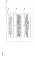
- Figure 3 is a flow diagram of an example method 300 for producing a continuous survey of a previously drilled portion of a wellbore in accordance with certain embodiments described herein.
- the method 300 comprises receiving a plurality of stationary survey measurements 212 (e.g., a plurality of gyrocompassing survey measurements) taken at a corresponding plurality of locations along the portion of the wellbore.
- the method 300 further comprises receiving at least one continuous survey 214 comprising a plurality of continuous survey measurements 216 taken between a pair of stationary survey measurements 212 of the plurality of stationary survey measurements 212.
- the method 300 further comprises combining the plurality of stationary survey measurements 212 and the plurality of continuous survey measurements 216 to produce a continuous survey of the portion of the wellbore.
- receiving the plurality of stationary survey measurements 212 in the operational block 310 comprises taking the plurality of stationary survey measurements 212 (e.g., as in the operational block 210) using the at least one survey tool.
- receiving the at least one continuous survey 214 in the operational block 320 comprises taking the at least one continuous survey 214 (e.g., as in the operational block 220) using the at least one survey tool.
- combining the plurality of stationary survey measurements 212 and the plurality of continuous survey measurements 216 in the operational block 330 comprises using a computer system comprising at least one processor (e.g., the at least one processor 130 described herein), the computer system having received the plurality of stationary survey measurements 212 taken by and transmitted from the at least one survey tool and the plurality of continuous survey measurements 216 taken by and transmitted from the at least one survey tool.
- a computer system comprising at least one processor (e.g., the at least one processor 130 described herein)
- the computer system having received the plurality of stationary survey measurements 212 taken by and transmitted from the at least one survey tool and the plurality of continuous survey measurements 216 taken by and transmitted from the at least one survey tool.
- the at least one continuous survey 214 comprises continuous survey measurements 216 taken between a pair of sequential stationary survey measurements 212 spaced from one another by a distance along the wellbore in a range of 30 feet to 270 feet (e.g., 90 feet, 180 feet, a length corresponding to one pipe length of the wellbore, a length corresponding to two pipe lengths of the wellbore, a length corresponding to three pipe lengths of the wellbore).
- Figures 4A-4E schematically illustrate various examples of the stationary survey measurements 212 and the continuous surveys 214 in accordance with certain embodiments described herein.
- the at least one continuous survey 214 comprising continuous survey measurements 216 taken between the pair of stationary survey measurements 212 spans across (e.g., includes) the location of at least one stationary survey measurement 212 (e.g., there are one or more stationary survey measurements 212 between the pair of stationary survey measurements 212).
- the continuous survey 214a comprising continuous survey measurements 216 taken between the pair of stationary survey measurements 212a, 212c spans across (e.g., includes) the location of the stationary survey measurement 212b.
- the at least one continuous survey 214 spans across (e.g., includes) the location of two or more stationary survey measurements 212.
- the continuous survey 214a comprising continuous survey measurements 216 taken between the pair of stationary survey measurements 212a, 212b spans across (e.g., includes) the locations of the stationary survey measurements 212a, 212b
- the continuous survey 214b comprising continuous survey measurements 216 taken between the pair of stationary survey measurements 212a, 212c spans across (e.g., includes) the locations of the stationary survey measurements 212b, 212c.
- the continuous survey 214 can include the locations of the pair of stationary survey measurements 212 that at least a portion of the continuous survey 214 is between.
- the continuous survey 214a comprising continuous survey measurements 216 taken between the pair of stationary survey measurements 212a, 212b spans across (e.g., includes) the location of the stationary survey measurement 212b
- the continuous survey 214b comprising continuous survey measurements 216 taken between the pair of stationary survey measurements 212b
- 212c spans across (e.g., includes) the location of the stationary survey measurement 212c
- the continuous survey 214a and the continuous survey 214b at least partially overlap one another.
- At least some of the continuous survey measurements 216 of the continuous survey 214a can also be continuous survey measurements 216 of the continuous survey 214b (e.g., some continuous survey measurements 216 can be included in two or more continuous surveys 214).
- the at least one continuous survey 214 comprising continuous survey measurements 216 taken between the pair of stationary survey measurements 212 spans across (e.g., includes) the locations of none of the stationary survey measurements 212 of the plurality of stationary survey measurements 212 (e.g., there are no stationary survey measurements 212 between the pair of stationary survey measurements 212 at either end of the continuous survey 214).
- the continuous survey 214a comprising continuous survey measurements 216 taken between the pair of stationary survey measurements 212a, 212b does not span across (e.g., include) a location of a stationary survey measurement 212
- the continuous survey 214b comprising continuous survey measurements 216 taken between the pair of stationary survey measurements 212b, 212c does not span across (e.g., include) a location of a stationary survey measurement 212.
- various combinations of continuous surveys 214 may be taken.
- the continuous survey 214a is between the pair of stationary survey measurements 212a, 212b without spanning across the locations of other stationary survey measurements 212
- the continuous survey 214b is between the pair of stationary survey measurements 212a, 212c and spans across (e.g., includes) the location of the stationary survey measurement 212b
- the continuous survey 214c is between the pair of stationary survey measurements 212b, 212c without spanning across the locations of other stationary survey measurements 212.
- Other combinations of continuous surveys 214 may also be taken in accordance with certain embodiments described herein.
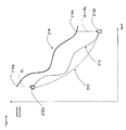
- Figures 5A and 5B schematically illustrate example processes for combining the plurality of stationary survey measurements 212 and the plurality of continuous survey measurements 216 to produce a continuous survey of the previously drilled portion of the wellbore in accordance with certain embodiments described herein.
- Figures 5A and 5B schematically show a plot of azimuth/inclination versus depth along the wellbore for survey measurements taken during an inrun survey.
- a pair of stationary survey measurements 212a, 212b (e.g., gyrocompassing survey measurements of azimuth and inclination taken at two different depths along the wellbore) are shown as squares, and a continuous survey 214 comprising a plurality of continuous survey measurements 216 between the stationary survey measurements 212a, 212b is shown as a solid line.
- the continuous survey 214 spans across (e.g., includes) the location of the stationary survey measurement 212b.
- a curve fitted to the two stationary survey measurements 212a, 212b by a minimum curvature method is shown by solid line 510
- a combined survey produced by combining the two stationary survey measurements 212a, 212b and the continuous survey measurements 216 of the continuous survey 214 is shown by solid line 512.
- the combined survey 512 provides information regarding the tortuosity of the wellbore between the two stationary survey measurements 212a, 212b, while the curve 510 fitted to the two stationary survey measurements 212 contains no such information.
- the pair of stationary survey measurements 212a, 212b can be used as the start point, the end point, or both for the range of continuous survey measurements 216 to be combined with the stationary survey measurements 212.
- This process can include adjusting the continuous survey measurements 216, which can comprise reducing (e.g., eliminating) a difference between at least one of the stationary survey measurements 212 of the pair of stationary survey measurements 212 and the continuous survey measurements 216 at the depth of the at least one of the stationary survey measurements 212.
- Each stationary survey measurement 212 can be used as the start point for the next continuous survey 214, and each segment of the continuous survey 216 can be appropriately adjusted and inserted between the corresponding pair of stationary survey measurements 212 to provide a combined survey.
- the continuous survey measurements 216 can be adjusted by applying an offset to the continuous survey measurements 216 at depths at or between the stationary survey measurement 212a and the stationary survey measurement 212b. In this way, the continuous survey measurement 216a (e.g., the start point of the continuous survey 214) taken at the depth of the stationary survey measurements 212a can be aligned with the stationary survey measurement 212a.
- the continuous survey measurement 216a e.g., the start point of the continuous survey 214 taken at the depth of the stationary survey measurements 212a can be aligned with the stationary survey measurement 212a.
- adjusting the continuous survey measurements 216 can comprise reducing (e.g., eliminating) a difference between at least one of the stationary survey measurements 212 of the pair of stationary survey measurements 212 and the continuous survey measurements 216 at a depth within a predetermined distance (e.g., within one foot, within five feet, within ten feet, within 10% of a length of a pipe of the wellbore) from the depth of the at least one of the stationary survey measurements 212.
- a predetermined distance e.g., within one foot, within five feet, within ten feet, within 10% of a length of a pipe of the wellbore
- the continuous survey data can be adjusted accordingly, in one or both of the inclination and azimuth readings.
- the start point 216a of the continuous survey data can be offset (e.g., shifted up or down by applying an offset) by a first amount ( ⁇ 1 ) such that the start point 216a of the continuous survey data is coincident with one stationary survey measurement 212a.
- the end point 216b of the continuous survey data can be offset (e.g., shifted up or down by applying an offset) by a second amount ( ⁇ 1 + ⁇ 2 ) such that the end point 216b is coincident with the other stationary survey measurement 212b.
- the individual measurements of the continuous survey data between the start point 216a and the end point 216b can then each be offset (e.g., shifted up or down by applying an offset) by a third amount calculated from an interpolation of the first amount and the second amount that is proportional to the distance of the depth of the individual measurement to the depths of the start point 216a and the end point 216b.
- the continuous survey data can be rigidly shifted up or down by a first amount such that the start point 216a is coincident with the one stationary survey measurement 212a, and the remaining measurements of the continuous survey data can then be rigidly rotated about the one stationary survey measurement 212a (e.g., rotated about the start point 216a in Figure 5A such that the continuous survey data maintains its shape) until the end point 216b of the continuous survey data coincides with or is within a predetermined amount from the other stationary survey measurement 212b.
- the stationary survey measurements 212 and the continuous survey measurements 216 collected over each wellbore section between successive stationary survey depths may be combined together by first computing a weighted average 218a of the start points 212a, 216a and a weighted average 218b of the end points 212b, 216b for the stationary survey measurements 212 and the continuous survey measurements 216 (e.g., for both inclination and azimuth).
- the weighting factors used can be based on representative error models for the two survey tools used to make these measurements.
- the weighted averages 218a, 218b of the start and end points can coincide closely with the start and end points 212a, 212b of the stationary survey measurements 212.
- the continuous survey data can be adjusted accordingly, in one or both of the inclination and azimuth readings.
- the start point 216a of the continuous survey data can be offset (e.g., shifted up or down by applying an offset) by a first amount ( ⁇ 1 ) such that the start point 216a of the continuous survey data is coincident with the weighted average start point 218a.
- the end point 216b of the continuous survey data can be offset (e.g., shifted up or down by applying an offset) by a second amount ( ⁇ 1 + ⁇ 2 ) such that the end point 216b is coincident with the weighted average end point 218b.
- the individual measurements of the continuous survey data between the start point 216a and the end point 216b can then be offset (e.g., shifted up or down by applying an offset) by a third amount calculated from an interpolation of the first amount and the second amount that is proportional to the distance of the depth of the individual measurement to the depths of the start point 216a and the end point 216b.
- the continuous survey data can be rigidly shifted up or down by a first amount such that the start point 216a is coincident with the weighted average start point 218a, and the remaining measurements of the continuous survey data can then be rigidly rotated about the weighted average start point 218a (e.g., rotated about the weighted average start point 218a in Figure 5B such that the continuous survey data maintains its shape) until the end point 216b of the continuous survey data coincides with or is within a predetermined amount from the weighted average end point 218b.
- the at least one gyroscopic sensor module 122b dedicated to continuous survey measurements can include lower-grade gyroscopic sensors that are significantly susceptible to bias errors (e.g., errors in azimuth, inclination, or both).
- bias errors e.g., errors in azimuth, inclination, or both.
- a comparison can be made (e.g., by the at least one processor 130 of the computer system) between the angular rates measured by the at least one gyroscopic sensor module 122a dedicated to stationary survey measurements and the at least one gyroscopic sensor module 122b dedicated to continuous survey measurements.
- Differences between the respective x-, y-, and z-axis measurements of these gyroscopic sensor modules 122a, 122b can be assumed to arise as a result of bias errors in the lower-grade sensors of the at least one gyroscopic sensor module 122b dedicated to continuous survey measurements. Based on this assumption, the measurement differences can be interpreted as errors in the lower-grade sensors and corrections can be applied accordingly (e.g., by applying an offset to the continuous survey 214, as shown in Figures 5A and 5B ).
- the process of correcting the continuous survey 214 can be extended to account for changes in the bias errors of the lower-grade sensors of the at least one gyroscopic sensor module 122b dedicated to continuous survey measurements.
- Figure 6 schematically illustrates an example process for correcting the continuous survey 214 for bias errors in accordance with certain embodiments described herein.
- the bias error can be assumed to have changed between a starting point of a continuous survey 214 and an ending point of the continuous survey 214 by a predetermined relationship (e.g., a linear change).
- the continuous survey measurements 216 taken at adjacent survey stations can be compared to these stationary survey measurements 212 to determine the bias errors (e.g., bias errors in azimuth, inclination, or both) of the continuous survey measurements 216 at these adjacent survey station locations (e.g., bias errors bias k and bias k + 1 ).
- the bias errors for the continuous survey measurements 216 at the locations between these two survey station locations can be assumed to have changed by a predetermined relationship (e.g., linear).
- the interpolated bias errors can be calculated using this predetermined relationship at locations between the pair of stationary survey measurements 212 (e.g., between the locations of survey station k and survey station k +1).
- the bias errors for the continuous survey measurements 216 at the locations between the two survey station locations can be corrected by applying offsets to correct for the interpolated bias errors. Such corrections can be made for each continuous survey 214 taken along the wellbore.
- additional adjustments can be made to the continuous survey 214 to combine it with the pair of stationary survey measurements 212 in a self-consistent manner.
- acts, events, or functions of any of the methods described herein can be performed in a different sequence, can be added, merged, or left out completely (e.g., not all described acts or events are necessary for the practice of the method).
- acts or events can be performed concurrently, e.g., through multi-threaded processing, interrupt processing, or multiple processors or processor cores, rather than sequentially.
- DSP digital signal processor
- ASIC application specific integrated circuit
- FPGA field programmable gate array
- a general purpose processor can be a microprocessor, but in the alternative, the processor can be any conventional processor, controller, microcontroller, or state machine.
- a processor can also be implemented as a combination of computing devices, e.g., a combination of a DSP and a microprocessor, a plurality of microprocessors, one or more microprocessors in conjunction with a DSP core, or any other such configuration.
- a software module can reside in RAM memory, flash memory, ROM memory, EPROM memory, EEPROM memory, registers, a hard disk, a removable disk, a CD-ROM, or any other form of computer-readable storage medium known in the art.
- An exemplary tangible, computer-readable storage medium is coupled to a processor such that the processor can read information from, and write information to, the storage medium.
- the storage medium can be integral to the processor.
- the processor and the storage medium can reside in an ASIC.
- the ASIC can reside in a user terminal.
- the processor and the storage medium can reside as discrete components in a user terminal.
Landscapes
- Engineering & Computer Science (AREA)
- Geology (AREA)
- Life Sciences & Earth Sciences (AREA)
- Mining & Mineral Resources (AREA)
- Physics & Mathematics (AREA)
- Geochemistry & Mineralogy (AREA)
- Fluid Mechanics (AREA)
- General Life Sciences & Earth Sciences (AREA)
- Environmental & Geological Engineering (AREA)
- Geophysics (AREA)
- General Physics & Mathematics (AREA)
- Radar, Positioning & Navigation (AREA)
- Remote Sensing (AREA)
- Gyroscopes (AREA)
- Geophysics And Detection Of Objects (AREA)
- Investigation Of Foundation Soil And Reinforcement Of Foundation Soil By Compacting Or Drainage (AREA)
Applications Claiming Priority (1)
| Application Number | Priority Date | Filing Date | Title |
|---|---|---|---|
| US14/446,140 US10077648B2 (en) | 2014-07-29 | 2014-07-29 | System and method for providing a continuous wellbore survey |
Publications (2)
| Publication Number | Publication Date |
|---|---|
| EP2980350A2 true EP2980350A2 (fr) | 2016-02-03 |
| EP2980350A3 EP2980350A3 (fr) | 2016-05-25 |
Family
ID=53762065
Family Applications (1)
| Application Number | Title | Priority Date | Filing Date |
|---|---|---|---|
| EP15178946.8A Ceased EP2980350A3 (fr) | 2014-07-29 | 2015-07-29 | Système et procédé pour fournir un relevé de puits continu |
Country Status (4)
| Country | Link |
|---|---|
| US (2) | US10077648B2 (fr) |
| EP (1) | EP2980350A3 (fr) |
| CA (1) | CA2897808A1 (fr) |
| MX (1) | MX2015009684A (fr) |
Cited By (1)
| Publication number | Priority date | Publication date | Assignee | Title |
|---|---|---|---|---|
| EP3721055A4 (fr) * | 2017-12-04 | 2021-09-22 | HRL Laboratories, LLC | Calcul de trajectoire continue pour forage directionnel |
Families Citing this family (17)
| Publication number | Priority date | Publication date | Assignee | Title |
|---|---|---|---|---|
| US10689969B2 (en) | 2014-07-29 | 2020-06-23 | Gyrodata, Incorporated | System and method for providing a continuous wellbore survey |
| US10781691B2 (en) | 2014-07-29 | 2020-09-22 | Gyrodata Incorporated | System and method for providing a continuous wellbore survey |
| US9911210B1 (en) * | 2014-12-03 | 2018-03-06 | Drilling Info, Inc. | Raster log digitization system and method |
| US10301925B2 (en) * | 2015-03-27 | 2019-05-28 | Vector Magnetics, Llc | Tracking system for drilling boreholes |
| US11118937B2 (en) | 2015-09-28 | 2021-09-14 | Hrl Laboratories, Llc | Adaptive downhole inertial measurement unit calibration method and apparatus for autonomous wellbore drilling |
| MX2018013666A (es) * | 2016-05-12 | 2019-07-18 | Magnetic Variation Services LLC | Metodo de perforacion de pozo hasta un objetivo. |
| US9863783B1 (en) * | 2016-10-12 | 2018-01-09 | Gyrodata, Incorporated | Correction of rotation rate measurements |
| EP3548701A4 (fr) * | 2016-11-29 | 2020-07-22 | HRL Laboratories, LLC | Système d'estimation de trajectoire incrémentale sur la base d'une détection inertielle en temps réel |
| GB2573973B (en) * | 2017-03-07 | 2022-04-13 | Gyrodata Inc | System and method for providing a continuous wellbore survey |
| US20180306025A1 (en) * | 2017-04-21 | 2018-10-25 | Gyrodata, Incorporated | Continuous Survey Using Magnetic Sensors |
| WO2019006411A1 (fr) * | 2017-06-30 | 2019-01-03 | Gyrodata, Incorporated | Relevé en continu à l'aide de capteurs de relevé |
| US11002131B2 (en) * | 2017-12-01 | 2021-05-11 | Gyrodata, Incorporated | Directional control of wellbore trajectories |
| GB2576756A (en) * | 2018-08-31 | 2020-03-04 | Gyro Tech Limited | Borehole survey instrument and method |
| US12110785B2 (en) * | 2018-11-20 | 2024-10-08 | Aps Technology, Llc | System and method for monitoring motion of downhole tool components of a drilling system |
| US20240141775A1 (en) * | 2021-03-05 | 2024-05-02 | Devico As | Survey tool system for blast hole drilling rigs |
| CN113790796B (zh) * | 2021-09-18 | 2023-12-05 | 国电投河南新能源有限公司 | 一种便于更换的风电塔筒用塔身振动监测结构 |
| GB2644201A (en) * | 2024-09-19 | 2026-03-25 | Ellison Env Services Ltd | Apparatus for assessing the installation of a ground source heat exchanger and associated test methods |
Citations (7)
| Publication number | Priority date | Publication date | Assignee | Title |
|---|---|---|---|---|
| EP0684490A2 (fr) * | 1994-05-26 | 1995-11-29 | Anadrill International SA | Procédés et dispositifs d'imagerie de formation en temps réel par télémétrie en cours de forage |
| US5657547A (en) | 1994-12-19 | 1997-08-19 | Gyrodata, Inc. | Rate gyro wells survey system including nulling system |
| US5821414A (en) | 1997-02-07 | 1998-10-13 | Noy; Koen | Survey apparatus and methods for directional wellbore wireline surveying |
| US6347282B2 (en) | 1997-12-04 | 2002-02-12 | Baker Hughes Incorporated | Measurement-while-drilling assembly using gyroscopic devices and methods of bias removal |
| US6957580B2 (en) | 2004-01-26 | 2005-10-25 | Gyrodata, Incorporated | System and method for measurements of depth and velocity of instrumentation within a wellbore |
| US7117605B2 (en) | 2004-04-13 | 2006-10-10 | Gyrodata, Incorporated | System and method for using microgyros to measure the orientation of a survey tool within a borehole |
| US7234539B2 (en) | 2003-07-10 | 2007-06-26 | Gyrodata, Incorporated | Method and apparatus for rescaling measurements while drilling in different environments |
Family Cites Families (19)
| Publication number | Priority date | Publication date | Assignee | Title |
|---|---|---|---|---|
| US5390748A (en) * | 1993-11-10 | 1995-02-21 | Goldman; William A. | Method and apparatus for drilling optimum subterranean well boreholes |
| US5452518A (en) | 1993-11-19 | 1995-09-26 | Baker Hughes Incorporated | Method of correcting for axial error components in magnetometer readings during wellbore survey operations |
| US6529834B1 (en) | 1997-12-04 | 2003-03-04 | Baker Hughes Incorporated | Measurement-while-drilling assembly using gyroscopic devices and methods of bias removal |
| CA2335075C (fr) | 1998-06-12 | 2004-12-14 | Baker Hughes Incorporated | Procede d'etalonnage de mesures magnetiques et d'estimation d'incertitude |
| US6209391B1 (en) | 1999-03-11 | 2001-04-03 | Tim Dallas | Free fall survey instrument |
| US6405808B1 (en) * | 2000-03-30 | 2002-06-18 | Schlumberger Technology Corporation | Method for increasing the efficiency of drilling a wellbore, improving the accuracy of its borehole trajectory and reducing the corresponding computed ellise of uncertainty |
| US6633816B2 (en) | 2000-07-20 | 2003-10-14 | Schlumberger Technology Corporation | Borehole survey method utilizing continuous measurements |
| US6807487B2 (en) * | 2001-05-11 | 2004-10-19 | Nonlinear Seismic Imaging, Inc. | Mapping permeable reservoir formations by measuring the elastic nonlinear interactions of a seismic wave as it propagates through the reservoir rock matrix and its pore fluids |
| GB0120076D0 (en) * | 2001-08-17 | 2001-10-10 | Schlumberger Holdings | Measurement of curvature of a subsurface borehole, and use of such measurement in directional drilling |
| US7066284B2 (en) * | 2001-11-14 | 2006-06-27 | Halliburton Energy Services, Inc. | Method and apparatus for a monodiameter wellbore, monodiameter casing, monobore, and/or monowell |
| US7650269B2 (en) * | 2004-11-15 | 2010-01-19 | Halliburton Energy Services, Inc. | Method and apparatus for surveying a borehole with a rotating sensor package |
| US7789171B2 (en) * | 2007-01-08 | 2010-09-07 | Halliburton Energy Services, Inc. | Device and method for measuring a property in a downhole apparatus |
| US20090078413A1 (en) | 2007-09-25 | 2009-03-26 | Tubel Paulo S | Wireless casing collar locator |
| BR112012010016A2 (pt) * | 2009-10-30 | 2018-03-27 | Sinvent As | sistema para inicialização azimute de um instrumento inercial e/ou giroscópio para topografia de poço, instrumento inercial e/ou giroscópio para topografia de poço, método para inicialização azimute de um instrumento inercial e/ou giroscópio para topografia de poço e uso de um sistema para inicialização azimute |
| US8579044B2 (en) | 2010-03-30 | 2013-11-12 | Gyrodata, Incorporated | Bending of a shaft of a steerable borehole drilling tool |
| US8596385B2 (en) * | 2011-12-22 | 2013-12-03 | Hunt Advanced Drilling Technologies, L.L.C. | System and method for determining incremental progression between survey points while drilling |
| CN105143598A (zh) * | 2013-02-27 | 2015-12-09 | 兰德马克绘图国际公司 | 用于预测钻井事故的方法和系统 |
| US10316639B2 (en) | 2014-02-21 | 2019-06-11 | Gyrodata, Incorporated | System and method for analyzing wellbore survey data to determine tortuosity of the wellbore using displacements of the wellbore path from reference lines |
| US10329896B2 (en) | 2014-02-21 | 2019-06-25 | Gyrodata, Incorporated | System and method for analyzing wellbore survey data to determine tortuosity of the wellbore using tortuosity parameter values |
-
2014
- 2014-07-29 US US14/446,140 patent/US10077648B2/en active Active
-
2015
- 2015-07-17 CA CA2897808A patent/CA2897808A1/fr not_active Abandoned
- 2015-07-27 MX MX2015009684A patent/MX2015009684A/es unknown
- 2015-07-29 EP EP15178946.8A patent/EP2980350A3/fr not_active Ceased
-
2018
- 2018-09-17 US US16/133,425 patent/US20190017367A1/en not_active Abandoned
Patent Citations (11)
| Publication number | Priority date | Publication date | Assignee | Title |
|---|---|---|---|---|
| EP0684490A2 (fr) * | 1994-05-26 | 1995-11-29 | Anadrill International SA | Procédés et dispositifs d'imagerie de formation en temps réel par télémétrie en cours de forage |
| US5657547A (en) | 1994-12-19 | 1997-08-19 | Gyrodata, Inc. | Rate gyro wells survey system including nulling system |
| US5806195A (en) | 1994-12-19 | 1998-09-15 | Uttecht; Gary | Rate gyro wells survey system including nulling system |
| US5821414A (en) | 1997-02-07 | 1998-10-13 | Noy; Koen | Survey apparatus and methods for directional wellbore wireline surveying |
| US6347282B2 (en) | 1997-12-04 | 2002-02-12 | Baker Hughes Incorporated | Measurement-while-drilling assembly using gyroscopic devices and methods of bias removal |
| US7234539B2 (en) | 2003-07-10 | 2007-06-26 | Gyrodata, Incorporated | Method and apparatus for rescaling measurements while drilling in different environments |
| US7669656B2 (en) | 2003-07-10 | 2010-03-02 | Gyrodata, Incorporated | Method and apparatus for rescaling measurements while drilling in different environments |
| US6957580B2 (en) | 2004-01-26 | 2005-10-25 | Gyrodata, Incorporated | System and method for measurements of depth and velocity of instrumentation within a wellbore |
| US7350410B2 (en) | 2004-01-26 | 2008-04-01 | Gyrodata, Inc. | System and method for measurements of depth and velocity of instrumentation within a wellbore |
| US7117605B2 (en) | 2004-04-13 | 2006-10-10 | Gyrodata, Incorporated | System and method for using microgyros to measure the orientation of a survey tool within a borehole |
| US7225550B2 (en) | 2004-04-13 | 2007-06-05 | Gyrodata Incorporated | System and method for using microgyros to measure the orientation of a survey tool within a borehole |
Non-Patent Citations (3)
| Title |
|---|
| G.W. UTTECHT; J.P. DEWARDT: "Survey Accuracy is Improved by a New, Small OD Gyro", WORLD OIL, March 1983 (1983-03-01) |
| SCHLUMBERGER: "At-bit inclination and gamma ray service", 31 December 2013 (2013-12-31), XP055433195, Retrieved from the Internet <URL:http://www.slb.com/-/media/Files/drilling/product_sheets/mwd/pathfinder_mwd/pzig_at_bit_gr_measurements_ps.pdf?la=en&hash=27472FFEF4C0C01870CE347328175E208022A23C> [retrieved on 20171208] * |
| SCHLUMBERGER: "PZIG 675", 31 December 2013 (2013-12-31), XP055433204, Retrieved from the Internet <URL:http://www.slb.com/-/media/Files/drilling/product_sheets/mwd/pathfinder_mwd/pzig_675_ps.pdf?la=en&hash=D90AAE06A9F8C3C045FBCA02E31493D0ABC2BE06> [retrieved on 20171208] * |
Cited By (2)
| Publication number | Priority date | Publication date | Assignee | Title |
|---|---|---|---|---|
| EP3721055A4 (fr) * | 2017-12-04 | 2021-09-22 | HRL Laboratories, LLC | Calcul de trajectoire continue pour forage directionnel |
| US11299981B2 (en) | 2017-12-04 | 2022-04-12 | Hrl Laboratories, Llc | Continuous trajectory calculation for directional drilling |
Also Published As
| Publication number | Publication date |
|---|---|
| US10077648B2 (en) | 2018-09-18 |
| CA2897808A1 (fr) | 2016-01-29 |
| EP2980350A3 (fr) | 2016-05-25 |
| MX2015009684A (es) | 2016-03-18 |
| US20160032709A1 (en) | 2016-02-04 |
| US20190017367A1 (en) | 2019-01-17 |
Similar Documents
| Publication | Publication Date | Title |
|---|---|---|
| US10077648B2 (en) | System and method for providing a continuous wellbore survey | |
| US10781691B2 (en) | System and method for providing a continuous wellbore survey | |
| US10689969B2 (en) | System and method for providing a continuous wellbore survey | |
| US10047600B2 (en) | Attitude reference for tieback/overlap processing | |
| US20190330979A1 (en) | System and Method for Providing a Continuous Wellbore Survey | |
| US20180306944A1 (en) | Continuous Survey Using Survey Sensors | |
| US12392237B2 (en) | System and method for using a magnetometer in a gyro-while-drilling survey tool | |
| EP2927419B1 (fr) | Système et procédé de surveillance de rotation d'outil pendant un sondage de puits de forage par gyrocompas | |
| US11041376B2 (en) | Gyro-magnetic wellbore surveying | |
| NO20191255A1 (en) | Continuous survey using magnetic sensors | |
| US11175431B2 (en) | Gyro-magnetic wellbore surveying | |
| WO2019006410A1 (fr) | Système et procédé pour fournir un relevé en continu de puits de forage | |
| NO20191187A1 (en) | System and method for providing a continuous wellbore survey | |
| WO2019006411A1 (fr) | Relevé en continu à l'aide de capteurs de relevé |
Legal Events
| Date | Code | Title | Description |
|---|---|---|---|
| PUAI | Public reference made under article 153(3) epc to a published international application that has entered the european phase |
Free format text: ORIGINAL CODE: 0009012 |
|
| AK | Designated contracting states |
Kind code of ref document: A2 Designated state(s): AL AT BE BG CH CY CZ DE DK EE ES FI FR GB GR HR HU IE IS IT LI LT LU LV MC MK MT NL NO PL PT RO RS SE SI SK SM TR |
|
| AX | Request for extension of the european patent |
Extension state: BA ME |
|
| PUAL | Search report despatched |
Free format text: ORIGINAL CODE: 0009013 |
|
| AK | Designated contracting states |
Kind code of ref document: A3 Designated state(s): AL AT BE BG CH CY CZ DE DK EE ES FI FR GB GR HR HU IE IS IT LI LT LU LV MC MK MT NL NO PL PT RO RS SE SI SK SM TR |
|
| AX | Request for extension of the european patent |
Extension state: BA ME |
|
| RIC1 | Information provided on ipc code assigned before grant |
Ipc: E21B 47/022 20120101AFI20160419BHEP Ipc: E21B 7/04 20060101ALI20160419BHEP Ipc: E21B 7/10 20060101ALI20160419BHEP |
|
| STAA | Information on the status of an ep patent application or granted ep patent |
Free format text: STATUS: REQUEST FOR EXAMINATION WAS MADE |
|
| 17P | Request for examination filed |
Effective date: 20161122 |
|
| RBV | Designated contracting states (corrected) |
Designated state(s): AL AT BE BG CH CY CZ DE DK EE ES FI FR GB GR HR HU IE IS IT LI LT LU LV MC MK MT NL NO PL PT RO RS SE SI SK SM TR |
|
| STAA | Information on the status of an ep patent application or granted ep patent |
Free format text: STATUS: EXAMINATION IS IN PROGRESS |
|
| 17Q | First examination report despatched |
Effective date: 20171219 |
|
| RIN1 | Information on inventor provided before grant (corrected) |
Inventor name: WESTON, JOHN LIONEL Inventor name: LEDROZ, ADRIAN GUILLERMO |
|
| STAA | Information on the status of an ep patent application or granted ep patent |
Free format text: STATUS: THE APPLICATION HAS BEEN REFUSED |
|
| 18R | Application refused |
Effective date: 20220911 |