EP2980363A1 - Machine et procédé de fonctionnement de la machine - Google Patents
Machine et procédé de fonctionnement de la machine Download PDFInfo
- Publication number
- EP2980363A1 EP2980363A1 EP14179077.4A EP14179077A EP2980363A1 EP 2980363 A1 EP2980363 A1 EP 2980363A1 EP 14179077 A EP14179077 A EP 14179077A EP 2980363 A1 EP2980363 A1 EP 2980363A1
- Authority
- EP
- European Patent Office
- Prior art keywords
- shaft
- face
- bearing
- partition plate
- chamber
- Prior art date
- Legal status (The legal status is an assumption and is not a legal conclusion. Google has not performed a legal analysis and makes no representation as to the accuracy of the status listed.)
- Withdrawn
Links
- 238000000034 method Methods 0.000 title claims description 5
- 238000005192 partition Methods 0.000 claims abstract description 56
- 230000004888 barrier function Effects 0.000 claims abstract description 40
- 239000012530 fluid Substances 0.000 claims abstract description 35
- 230000001050 lubricating effect Effects 0.000 claims abstract description 14
- 230000000903 blocking effect Effects 0.000 claims abstract description 9
- 125000006850 spacer group Chemical group 0.000 claims description 6
- 239000012080 ambient air Substances 0.000 claims description 3
- 239000007789 gas Substances 0.000 description 15
- 238000007789 sealing Methods 0.000 description 5
- 230000000694 effects Effects 0.000 description 3
- 238000006073 displacement reaction Methods 0.000 description 2
- 230000015572 biosynthetic process Effects 0.000 description 1
- 239000000571 coke Substances 0.000 description 1
- 230000007423 decrease Effects 0.000 description 1
- 238000009413 insulation Methods 0.000 description 1
- 238000009420 retrofitting Methods 0.000 description 1
- 238000000926 separation method Methods 0.000 description 1
Images

Classifications
-
- F—MECHANICAL ENGINEERING; LIGHTING; HEATING; WEAPONS; BLASTING
- F01—MACHINES OR ENGINES IN GENERAL; ENGINE PLANTS IN GENERAL; STEAM ENGINES
- F01D—NON-POSITIVE DISPLACEMENT MACHINES OR ENGINES, e.g. STEAM TURBINES
- F01D11/00—Preventing or minimising internal leakage of working-fluid, e.g. between stages
- F01D11/02—Preventing or minimising internal leakage of working-fluid, e.g. between stages by non-contact sealings, e.g. of labyrinth type
- F01D11/04—Preventing or minimising internal leakage of working-fluid, e.g. between stages by non-contact sealings, e.g. of labyrinth type using sealing fluid, e.g. steam
- F01D11/06—Control thereof
-
- F—MECHANICAL ENGINEERING; LIGHTING; HEATING; WEAPONS; BLASTING
- F01—MACHINES OR ENGINES IN GENERAL; ENGINE PLANTS IN GENERAL; STEAM ENGINES
- F01D—NON-POSITIVE DISPLACEMENT MACHINES OR ENGINES, e.g. STEAM TURBINES
- F01D11/00—Preventing or minimising internal leakage of working-fluid, e.g. between stages
- F01D11/02—Preventing or minimising internal leakage of working-fluid, e.g. between stages by non-contact sealings, e.g. of labyrinth type
- F01D11/04—Preventing or minimising internal leakage of working-fluid, e.g. between stages by non-contact sealings, e.g. of labyrinth type using sealing fluid, e.g. steam
-
- F—MECHANICAL ENGINEERING; LIGHTING; HEATING; WEAPONS; BLASTING
- F01—MACHINES OR ENGINES IN GENERAL; ENGINE PLANTS IN GENERAL; STEAM ENGINES
- F01D—NON-POSITIVE DISPLACEMENT MACHINES OR ENGINES, e.g. STEAM TURBINES
- F01D25/00—Component parts, details, or accessories, not provided for in, or of interest apart from, other groups
- F01D25/16—Arrangement of bearings; Supporting or mounting bearings in casings
- F01D25/166—Sliding contact bearing
-
- F—MECHANICAL ENGINEERING; LIGHTING; HEATING; WEAPONS; BLASTING
- F01—MACHINES OR ENGINES IN GENERAL; ENGINE PLANTS IN GENERAL; STEAM ENGINES
- F01D—NON-POSITIVE DISPLACEMENT MACHINES OR ENGINES, e.g. STEAM TURBINES
- F01D25/00—Component parts, details, or accessories, not provided for in, or of interest apart from, other groups
- F01D25/18—Lubricating arrangements
-
- F—MECHANICAL ENGINEERING; LIGHTING; HEATING; WEAPONS; BLASTING
- F01—MACHINES OR ENGINES IN GENERAL; ENGINE PLANTS IN GENERAL; STEAM ENGINES
- F01D—NON-POSITIVE DISPLACEMENT MACHINES OR ENGINES, e.g. STEAM TURBINES
- F01D25/00—Component parts, details, or accessories, not provided for in, or of interest apart from, other groups
- F01D25/18—Lubricating arrangements
- F01D25/183—Sealing means
- F01D25/186—Sealing means for sliding contact bearing
-
- F—MECHANICAL ENGINEERING; LIGHTING; HEATING; WEAPONS; BLASTING
- F02—COMBUSTION ENGINES; HOT-GAS OR COMBUSTION-PRODUCT ENGINE PLANTS
- F02C—GAS-TURBINE PLANTS; AIR INTAKES FOR JET-PROPULSION PLANTS; CONTROLLING FUEL SUPPLY IN AIR-BREATHING JET-PROPULSION PLANTS
- F02C7/00—Features, components parts, details or accessories, not provided for in, or of interest apart form groups F02C1/00 - F02C6/00; Air intakes for jet-propulsion plants
- F02C7/06—Arrangements of bearings; Lubricating
-
- F—MECHANICAL ENGINEERING; LIGHTING; HEATING; WEAPONS; BLASTING
- F16—ENGINEERING ELEMENTS AND UNITS; GENERAL MEASURES FOR PRODUCING AND MAINTAINING EFFECTIVE FUNCTIONING OF MACHINES OR INSTALLATIONS; THERMAL INSULATION IN GENERAL
- F16J—PISTONS; CYLINDERS; SEALINGS
- F16J15/00—Sealings
- F16J15/44—Free-space packings
- F16J15/447—Labyrinth packings
- F16J15/4476—Labyrinth packings with radial path
-
- F—MECHANICAL ENGINEERING; LIGHTING; HEATING; WEAPONS; BLASTING
- F02—COMBUSTION ENGINES; HOT-GAS OR COMBUSTION-PRODUCT ENGINE PLANTS
- F02C—GAS-TURBINE PLANTS; AIR INTAKES FOR JET-PROPULSION PLANTS; CONTROLLING FUEL SUPPLY IN AIR-BREATHING JET-PROPULSION PLANTS
- F02C7/00—Features, components parts, details or accessories, not provided for in, or of interest apart form groups F02C1/00 - F02C6/00; Air intakes for jet-propulsion plants
- F02C7/28—Arrangement of seals
-
- F—MECHANICAL ENGINEERING; LIGHTING; HEATING; WEAPONS; BLASTING
- F04—POSITIVE - DISPLACEMENT MACHINES FOR LIQUIDS; PUMPS FOR LIQUIDS OR ELASTIC FLUIDS
- F04D—NON-POSITIVE-DISPLACEMENT PUMPS
- F04D29/00—Details, component parts, or accessories
- F04D29/08—Sealings
- F04D29/10—Shaft sealings
- F04D29/102—Shaft sealings especially adapted for elastic fluid pumps
- F04D29/104—Shaft sealings especially adapted for elastic fluid pumps the sealing fluid being other than the working fluid or being the working fluid treated
Definitions
- the invention relates to a machine with a shaft and a bearing and a method for operating the machine.
- a machine such as a turbomachine, having a shaft and an oil lubricated bearing may be provided with a seal gas seal to prevent the oil from leaking out of the bearing.
- the seal gas seal may include a barrier chamber between a radially extending rotating shaft wall and the stationary bearing housing.
- the barrier fluid in the barrier chamber is caused to rotate by friction on the shaft wall.
- the rotating barrier fluid is formed by the action of centrifugal forces a pressure drop radially inward, which disadvantageously the pressure on the bearing housing is low, so that the oil can escape from the bearing housing.
- the leakage of the oil is particularly critical when it occurs at the turbine outlet of a gas turbine, because here the oil can come into contact with hot parts of the gas turbine.
- the oil may coke or burn through contact, thereby jeopardizing the safe operation of the machine.
- the problem is solved in which the sealing gas seal is subjected to the barrier fluid under high pressure, which is disadvantageous for the efficiency of the gas turbine.
- the object of the invention is to provide a machine with a shaft and a bearing and a method for operating the machine, wherein a good sealing effect against the bearing is achieved.
- the machine according to the invention comprises a shaft having a step such that a first shaft section having a first diameter, a second shaft section having a second diameter which is shorter than the first diameter, and a radially extending and rotatable shaft end face are formed
- a housing and a bearing which supports the shaft at its second shaft portion on the housing and is lubricated with a lubricating fluid, wherein the shaft end face a radially extending and stationary bearing face, whereby one with a barrier fluid, by means of the leakage of the lubricating fluid the bearing can be prevented, acted upon lock chamber is formed, which is bounded axially from the shaft end face and the bearing end and radially inward of the second shaft portion released from the bearing, characterized in that in the lock chamber, a radially extending and fixed Tre nnplatte is introduced so that an aerodynamic shielding of the bearing end side of the shaft end face takes place, whereby the area between the partition plate and the bearing end face during rotation of the shaft is substantially vortex-free
- the area between the separating plate and the bearing end face is axially bounded by no rotating walls, so that no pressure-determining vortices can form in this area.
- the area between the shaft end face and the partition plate is axially bounded by a rotating wall, namely the bearing face, so that a vortex can form in this area.
- this vortex does not affect the area between the partition plate and the bearing face due to the shielding effect of the partition plate.
- the barrier fluid in the area between the partition plate and the bearing face has substantially the pressure applied to the barrier chamber and is exposed only to wall friction losses.
- the pressure of the barrier fluid at the bearing end side is high, whereby a good sealing effect against the bearing can be achieved.
- the partition plate provides such a simple constructive measure that existing machines can also be retrofitted with the partition plate.
- a radial gap is formed between the radially inner longitudinal end of the partition plate and the shaft. This advantageously prevents grinding of the partition plate on the shaft.
- the radial gap preferably has an extent in the radial direction of 0.1 mm to 10 mm. Due to the lower limit of 0.1 mm can advantageously be prevented from grinding.
- the upper limit of 10 mm advantageously ensures that no vortex is formed in the region between the separating plate and the bearing end face. The upper limit also ensures that not so much barrier fluid can reach via the radial gap in the area between the shaft end face and the partition plate, that the pressure at the bearing end side substantially decreases.
- the partition plate is arranged parallel to the shaft end surface and the bearing end face.
- the partition plate preferably has a distance from the shaft end face of 0.25 * d to 0.75 * d, more preferably 0.5 * d to 0.75 * d, particularly preferably 0.5 * d, wherein d is the distance between the shaft end face and the bearing end face.
- the minimum distance of the partition plate of the shaft end face is also advantageously ensured that the barrier fluid does not heat up significantly by friction.
- the partition plate is positioned closer to the bearing face rather than to the shaft end face to minimize the shear forces in the area between the rotating shaft face and the separation plate.
- the partition plate preferably extends radially outward substantially to at least the radially outer end of the shaft end face.
- a shield of the bearing end side of the shaft end face is advantageously achieved that the area between the partition plate and the bearing end face during rotation of the shaft is substantially free of eddy.
- the partition plate is arranged annularly around the shaft.
- the partition plate is preferably fixed by means attached to the bearing end face and on the partition plate spacers. This makes it possible to install the separator plate together with the bearing in the machine or remove it from the machine.
- the bearing represents a wearing part of the machine and retrofitting the machine with the separating plate can thus be carried out particularly easily during a routine replacement of the bearing.
- the machine is a turbomachine, in particular a gas turbine. It is further particularly preferred that the barrier chamber is arranged with the partition plate at the turbine outlet of the gas turbine. It is advantageous to provide the partition plate here, because leakage of the lubricating fluid at the turbine outlet of the gas turbine is particularly critical, since it can come into contact there with hot exhaust gases and hot parts of the gas turbine and thereby burn.
- the method according to the invention for operating a machine comprises the steps of: rotating the shaft; Inflicting the barrier chamber with ambient air under atmospheric conditions as the barrier fluid, whereby leakage of the lubricating fluid from the bearing is prevented in the barrier chamber.
- ambient air is used, in particular from a Sound insulation of the machine is taken, the efficiency of the machine is high.
- the separating plate By providing the separating plate, leakage of the lubricating fluid from the bearing into the barrier chamber under all operating conditions can be prevented.
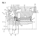
- a machine 1 has a shaft 2 which is rotatable about a shaft axis 8. Furthermore, the shaft 2 has a step 3, whereby the shaft 2 has in the axial direction a first shaft section 9 with a first radius 11 and a second shaft section 10 with a second radius 12. The second radius 12 is shorter than the first radius 11.
- the shaft 2 has a rotatable shaft end face 6, which is arranged in the interface between the first shaft portion 10 and the second shaft portion 11 and radially between the first radius eleventh and the second radius 12 extends. The shaft end face 6 is thereby annular.
- the machine 1 further comprises a fixed housing 5 and a bearing 4, which supports the shaft 2 at its second shaft portion 10 on the housing 5.
- the bearing 4 is lubricated with a lubricating fluid, in particular oil, and is in particular a plain bearing.
- the bearing 4 has a fixed bearing end face 7, which is arranged parallel to the shaft end face 6 and the shaft end face 6 facing. Radially outside the bearing end face 7, a fixed housing end face 30 is arranged, which is likewise arranged facing the shaft end face 6.
- the machine 1 has a blocking chamber 13, which is acted upon by a blocking fluid during operation of the machine 1 in order to prevent leakage of the lubricating fluid from the bearing 4 into the blocking chamber 13.
- the lock chamber 13 is axially delimited by the shaft end face 6 and the bearing end face 7. Radially inside, the lock chamber 13 is bounded by the radial outside of the section of the second shaft section 10 extending from the shaft end face 6 to the bearing end face 7.
- the bearing 4 has a bearing seal 14 for sealing the bearing 4 to the locking chamber 13 out.
- the bearing seal 14 is arranged on the radial outer side of the shaft 2 in the region of the second shaft section 10 and in the region of the bearing end face 7. In order to prevent leakage of the lubricating fluid from the bearing 4, it is necessary that the pressure of the barrier fluid at the end of the bearing seal 14 facing the stopper chamber 13 is higher than the pressure of the lubricating fluid at this end.
- the partition plate 15 In the barrier chamber 13 is a fixed and radially extending partition plate 15 is introduced.
- the partition plate 15 may be a sheet, for example.
- the partition plate 15 is arranged with its long side parallel to the shaft end face 6 and the bearing end face 7 and annular.
- a rotor-stator chamber 27 extending from the shaft end face 6 to the partition plate 15 and a stator-stator chamber 28 are formed extending from the partition plate 15 to the bearing end face 7 extends.
- the rotor-stator chamber 27 and the stator-stator chamber 28 are arranged side by side in the axial direction.
- a radial gap 16 is formed, which has an extension of 0.1 mm to 10 mm in the radial direction.
- the partition plate 15 has a distance from the shaft end surface 6, which is from 0.25 * d to 0.75 * d, where d is the distance between the shaft end face 6 and the bearing end face 7. Radially outward, the partition plate 15 extends according to FIGS. 1 to 3 essentially up to the first radius 11. However, it is conceivable to carry out the partition plate 15 further radially outward.
- the blocking chamber 13 has a first recess 25, which is introduced into the shaft 2 and connects radially outward to the first radius 11. Through the first recess 25, a recess end surface 29 is formed, which is arranged facing the bearing end face 7.
- the locking chamber 15 also has a second recess 26 which extends radially outward.
- the barrier fluid can pass from the environment 23 of the machine 1 into the barrier chamber 13 via an outer gap 22, a channel 24 and the second recess 26.
- a turbine gap 20 extends from the barrier chamber 13 to a turbine interior.
- the turbine gap 20 has a turbine seal 21. So that no exhaust gas from the turbine interior via the turbine gap 20 can get into the barrier chamber 13, it is necessary that the pressure of the sealing gas in the barrier chamber 13 is higher than the pressure of the exhaust gas.
- the machine 1 has a plurality of spacers 17, which are respectively attached to the bearing end face 7 and to the partition plate 15 to fix the partition plate 17.
- Each of the spacers 17 is passed through a respective hole in the partition plate 15 and has a spacer head with which the axial displacement of the partition plate 15 toward the shaft end surface 6 is limited.
- Each spacer 17 is enveloped by a sleeve 19, with which the axial displacement of the partition plate 15 is limited in the direction of the bearing end face 7.
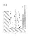
- the adjusting in the lock chamber 13 during rotation of the shaft 2 flow conditions are in FIG. 3 shown.
- a flow is established in the blocking chamber 13, which is driven because the blocking fluid is transported radially outward on the rotating shaft end face 6 by friction.
- the blocking fluid flows radially inwards on the separating plate 15, so that a vortex is formed in the rotor-stator chamber 27.
- a flow is formed, which is directed substantially radially inward and is directed through the radial gap 16 in the direction of the rotor-stator chamber 27.
- the stator-stator chamber 28 so the area between the partition plate 15 and the bearing end face 7, substantially free of eddy.
- stator-stator chamber 28 small vortices can be formed in corners or at edges, but these small vortices can not determine the pressure in the stator-stator chamber 27.
- the pressure at the bearing end face 7 is higher than would be the case for a barrier chamber without partition plate.
- CFD calculations for some selected cases have shown that the pressure at the bearing end face 7 at the radially inner end of the barrier chamber 13 is higher by 2 mbar to 3 mbar than would be the case for the barrier chamber without a partition plate.
- the pressure on the shaft end face 6 is higher than would be the case for the barrier chamber without partition plate, because the vortex in the rotor-stator chamber 28 gets impressed by the flow through the radial gap 16, a higher pressure.
- the CFD calculations have shown that the pressure at the shaft end face 6 at the radially inner end of the barrier chamber 13 is higher by 1.5 mbar to 2.5 mbar than would be the case for the barrier chamber without a partition plate.
- the partition plate 15 according to FIGS. 1 to 3 Although here extends only substantially to the first radius 11, but the area radially outside the radius 11 is not critical, because here the distance between the recess end face 29 and the bearing end face 7 and / or the housing end face 30 is sufficiently large that no can form radial pressure gradient.
Landscapes
- Engineering & Computer Science (AREA)
- General Engineering & Computer Science (AREA)
- Mechanical Engineering (AREA)
- Chemical & Material Sciences (AREA)
- Combustion & Propulsion (AREA)
- Sealing Using Fluids, Sealing Without Contact, And Removal Of Oil (AREA)
- Rolling Contact Bearings (AREA)
- Turbine Rotor Nozzle Sealing (AREA)
Priority Applications (5)
| Application Number | Priority Date | Filing Date | Title |
|---|---|---|---|
| EP14179077.4A EP2980363A1 (fr) | 2014-07-30 | 2014-07-30 | Machine et procédé de fonctionnement de la machine |
| PCT/EP2015/066640 WO2016016048A1 (fr) | 2014-07-30 | 2015-07-21 | Machine et procédé pour faire fonctionner la machine |
| CN201580039720.1A CN106536868B (zh) | 2014-07-30 | 2015-07-21 | 机器和用于操作机器的方法 |
| US15/320,607 US10570769B2 (en) | 2014-07-30 | 2015-07-21 | Machine and method for operating the machine |
| EP15744517.2A EP3129604B1 (fr) | 2014-07-30 | 2015-07-21 | Machine avec un arbre et un palier |
Applications Claiming Priority (1)
| Application Number | Priority Date | Filing Date | Title |
|---|---|---|---|
| EP14179077.4A EP2980363A1 (fr) | 2014-07-30 | 2014-07-30 | Machine et procédé de fonctionnement de la machine |
Publications (1)
| Publication Number | Publication Date |
|---|---|
| EP2980363A1 true EP2980363A1 (fr) | 2016-02-03 |
Family
ID=51260650
Family Applications (2)
| Application Number | Title | Priority Date | Filing Date |
|---|---|---|---|
| EP14179077.4A Withdrawn EP2980363A1 (fr) | 2014-07-30 | 2014-07-30 | Machine et procédé de fonctionnement de la machine |
| EP15744517.2A Active EP3129604B1 (fr) | 2014-07-30 | 2015-07-21 | Machine avec un arbre et un palier |
Family Applications After (1)
| Application Number | Title | Priority Date | Filing Date |
|---|---|---|---|
| EP15744517.2A Active EP3129604B1 (fr) | 2014-07-30 | 2015-07-21 | Machine avec un arbre et un palier |
Country Status (4)
| Country | Link |
|---|---|
| US (1) | US10570769B2 (fr) |
| EP (2) | EP2980363A1 (fr) |
| CN (1) | CN106536868B (fr) |
| WO (1) | WO2016016048A1 (fr) |
Citations (3)
| Publication number | Priority date | Publication date | Assignee | Title |
|---|---|---|---|---|
| GB2167141A (en) * | 1984-11-13 | 1986-05-21 | Maschf Augsburg Nuernberg Ag | Fluid/face - seal for shaft |
| DE4420973A1 (de) * | 1994-06-16 | 1995-12-21 | Abb Management Ag | Wellendichtung einer thermischen Turbomaschine |
| US20120201661A1 (en) * | 2011-02-07 | 2012-08-09 | General Electric Company | Contaminant shield system for a shaft |
Family Cites Families (2)
| Publication number | Priority date | Publication date | Assignee | Title |
|---|---|---|---|---|
| GB1045973A (en) * | 1962-07-14 | 1966-10-19 | Walter Eberspacher | Exhaust turbo supercharger |
| JP4773804B2 (ja) | 2005-11-17 | 2011-09-14 | 三菱重工業株式会社 | ガスタービン |
-
2014
- 2014-07-30 EP EP14179077.4A patent/EP2980363A1/fr not_active Withdrawn
-
2015
- 2015-07-21 CN CN201580039720.1A patent/CN106536868B/zh active Active
- 2015-07-21 EP EP15744517.2A patent/EP3129604B1/fr active Active
- 2015-07-21 WO PCT/EP2015/066640 patent/WO2016016048A1/fr not_active Ceased
- 2015-07-21 US US15/320,607 patent/US10570769B2/en active Active
Patent Citations (3)
| Publication number | Priority date | Publication date | Assignee | Title |
|---|---|---|---|---|
| GB2167141A (en) * | 1984-11-13 | 1986-05-21 | Maschf Augsburg Nuernberg Ag | Fluid/face - seal for shaft |
| DE4420973A1 (de) * | 1994-06-16 | 1995-12-21 | Abb Management Ag | Wellendichtung einer thermischen Turbomaschine |
| US20120201661A1 (en) * | 2011-02-07 | 2012-08-09 | General Electric Company | Contaminant shield system for a shaft |
Also Published As
| Publication number | Publication date |
|---|---|
| US10570769B2 (en) | 2020-02-25 |
| US20180209289A1 (en) | 2018-07-26 |
| CN106536868A (zh) | 2017-03-22 |
| WO2016016048A1 (fr) | 2016-02-04 |
| CN106536868B (zh) | 2018-05-11 |
| EP3129604A1 (fr) | 2017-02-15 |
| EP3129604B1 (fr) | 2018-12-05 |
Similar Documents
| Publication | Publication Date | Title |
|---|---|---|
| EP3234415B1 (fr) | Dispositif d'étanchéité d'arbre d'une machine hydraulique et procédé d'étanchéité d'un arbre d'une machine hydraulique | |
| EP3056813B1 (fr) | Joint pour un interstice marginal entre les bardeaux d'effusion d'une chambre de combustion de turbines a gaz | |
| DE102009044089A1 (de) | Verfahren und Vorrichtung zur Anpassung der thermisch wirksamen Masse und Steifigkeit von verschraubten Teilringen | |
| EP2169282A1 (fr) | Agencement doté d'un joint d'étanchéité d'arbre | |
| DE102014208738B3 (de) | Gleitringdichtungsanordnung mit verbesserter Gasabscheidung | |
| DE112018000772B4 (de) | Dampfturbine, die in der lage ist, erosion und wirkungsgradverschlechterung zu unterdrücken | |
| CH708850A2 (de) | Dichtungsringanordnung für eine drehende Maschine und Verfahren zur Montage derselben. | |
| DE102011055473A1 (de) | Strömungspfad für ein Dampfturbinenaußengehäuse und Strömungsbarrierevorrichtung | |
| EP3392471A2 (fr) | Logement de palier et compresseur turbo avec un logement de palier | |
| WO2017178203A1 (fr) | Aube de turbine, dispositif associé, turbomachine et utilisation | |
| EP2815129B1 (fr) | Agencement de joint et pompe dotée d'un agencement de joint | |
| CH708842A2 (de) | Leitschaufelanordnung zur Sicherung von Turbinenleitschaufeln innerhalb einer Nut eines Aussenrings. | |
| EP3399151B1 (fr) | Tôle de protection d'usure pour une aube mobile d'une turbine à gaz | |
| EP3129604B1 (fr) | Machine avec un arbre et un palier | |
| EP0690204B1 (fr) | Turbine à vapeur ayant au moins deux joint pour assurer l'étanchéité du carter | |
| DE102017207667A1 (de) | Verfahren zum Instandhalten einer Strömungsmaschine | |
| DE102005033364B4 (de) | Axialdampfturbinenanordnung | |
| EP2535621B1 (fr) | Joint d'étanchéité pour arbre pour un système d'huile de blocage d'un générateur refroidi à l'hydrogène | |
| EP3004562B1 (fr) | Elément d'insertion et turbine à gaz | |
| EP3225783B1 (fr) | Garniture de rodage pour un joint externe d'étanchéité à l'air d'une turbomachine | |
| DE102013203870B4 (de) | Verdrehsicherung für Turbomaschinen | |
| EP3220017A1 (fr) | Dispositif d'étanchéité pour turbine | |
| DE102016217286A1 (de) | Druckbehälter | |
| EP4348010B1 (fr) | Bague d'étanchéité d'un rotor et turbomachine comprenant le rotor | |
| EP3037626B1 (fr) | Dispositif d'étanchéité d'une turbine d'entraînement de compresseur |
Legal Events
| Date | Code | Title | Description |
|---|---|---|---|
| PUAI | Public reference made under article 153(3) epc to a published international application that has entered the european phase |
Free format text: ORIGINAL CODE: 0009012 |
|
| AK | Designated contracting states |
Kind code of ref document: A1 Designated state(s): AL AT BE BG CH CY CZ DE DK EE ES FI FR GB GR HR HU IE IS IT LI LT LU LV MC MK MT NL NO PL PT RO RS SE SI SK SM TR |
|
| AX | Request for extension of the european patent |
Extension state: BA ME |
|
| STAA | Information on the status of an ep patent application or granted ep patent |
Free format text: STATUS: THE APPLICATION IS DEEMED TO BE WITHDRAWN |
|
| 18D | Application deemed to be withdrawn |
Effective date: 20160804 |