EP2980601B1 - Procédé de télémétrie rf sécurisée sous fortes réflexions à trajets multiples - Google Patents
Procédé de télémétrie rf sécurisée sous fortes réflexions à trajets multiples Download PDFInfo
- Publication number
- EP2980601B1 EP2980601B1 EP15178725.6A EP15178725A EP2980601B1 EP 2980601 B1 EP2980601 B1 EP 2980601B1 EP 15178725 A EP15178725 A EP 15178725A EP 2980601 B1 EP2980601 B1 EP 2980601B1
- Authority
- EP
- European Patent Office
- Prior art keywords
- receiver
- gain
- lock
- signal
- determining
- Prior art date
- Legal status (The legal status is an assumption and is not a legal conclusion. Google has not performed a legal analysis and makes no representation as to the accuracy of the status listed.)
- Active
Links
Images





Classifications
-
- G—PHYSICS
- G01—MEASURING; TESTING
- G01S—RADIO DIRECTION-FINDING; RADIO NAVIGATION; DETERMINING DISTANCE OR VELOCITY BY USE OF RADIO WAVES; LOCATING OR PRESENCE-DETECTING BY USE OF THE REFLECTION OR RERADIATION OF RADIO WAVES; ANALOGOUS ARRANGEMENTS USING OTHER WAVES
- G01S13/00—Systems using the reflection or reradiation of radio waves, e.g. radar systems; Analogous systems using reflection or reradiation of waves whose nature or wavelength is irrelevant or unspecified
- G01S13/74—Systems using reradiation of radio waves, e.g. secondary radar systems; Analogous systems
- G01S13/76—Systems using reradiation of radio waves, e.g. secondary radar systems; Analogous systems wherein pulse-type signals are transmitted
- G01S13/767—Responders; Transponders
-
- G—PHYSICS
- G01—MEASURING; TESTING
- G01S—RADIO DIRECTION-FINDING; RADIO NAVIGATION; DETERMINING DISTANCE OR VELOCITY BY USE OF RADIO WAVES; LOCATING OR PRESENCE-DETECTING BY USE OF THE REFLECTION OR RERADIATION OF RADIO WAVES; ANALOGOUS ARRANGEMENTS USING OTHER WAVES
- G01S7/00—Details of systems according to groups G01S13/00, G01S15/00, G01S17/00
- G01S7/02—Details of systems according to groups G01S13/00, G01S15/00, G01S17/00 of systems according to group G01S13/00
- G01S7/28—Details of pulse systems
- G01S7/285—Receivers
- G01S7/292—Extracting wanted echo-signals
- G01S7/2921—Extracting wanted echo-signals based on data belonging to one radar period
-
- G—PHYSICS
- G01—MEASURING; TESTING
- G01S—RADIO DIRECTION-FINDING; RADIO NAVIGATION; DETERMINING DISTANCE OR VELOCITY BY USE OF RADIO WAVES; LOCATING OR PRESENCE-DETECTING BY USE OF THE REFLECTION OR RERADIATION OF RADIO WAVES; ANALOGOUS ARRANGEMENTS USING OTHER WAVES
- G01S11/00—Systems for determining distance or velocity not using reflection or reradiation
- G01S11/02—Systems for determining distance or velocity not using reflection or reradiation using radio waves
-
- G—PHYSICS
- G01—MEASURING; TESTING
- G01S—RADIO DIRECTION-FINDING; RADIO NAVIGATION; DETERMINING DISTANCE OR VELOCITY BY USE OF RADIO WAVES; LOCATING OR PRESENCE-DETECTING BY USE OF THE REFLECTION OR RERADIATION OF RADIO WAVES; ANALOGOUS ARRANGEMENTS USING OTHER WAVES
- G01S13/00—Systems using the reflection or reradiation of radio waves, e.g. radar systems; Analogous systems using reflection or reradiation of waves whose nature or wavelength is irrelevant or unspecified
- G01S13/74—Systems using reradiation of radio waves, e.g. secondary radar systems; Analogous systems
- G01S13/76—Systems using reradiation of radio waves, e.g. secondary radar systems; Analogous systems wherein pulse-type signals are transmitted
-
- G—PHYSICS
- G01—MEASURING; TESTING
- G01S—RADIO DIRECTION-FINDING; RADIO NAVIGATION; DETERMINING DISTANCE OR VELOCITY BY USE OF RADIO WAVES; LOCATING OR PRESENCE-DETECTING BY USE OF THE REFLECTION OR RERADIATION OF RADIO WAVES; ANALOGOUS ARRANGEMENTS USING OTHER WAVES
- G01S7/00—Details of systems according to groups G01S13/00, G01S15/00, G01S17/00
- G01S7/02—Details of systems according to groups G01S13/00, G01S15/00, G01S17/00 of systems according to group G01S13/00
- G01S7/28—Details of pulse systems
- G01S7/285—Receivers
- G01S7/34—Gain of receiver varied automatically during pulse-recurrence period, e.g. anti-clutter gain control
-
- H—ELECTRICITY
- H03—ELECTRONIC CIRCUITRY
- H03G—CONTROL OF AMPLIFICATION
- H03G3/00—Gain control in amplifiers or frequency changers
- H03G3/20—Automatic control
- H03G3/30—Automatic control in amplifiers having semiconductor devices
- H03G3/3036—Automatic control in amplifiers having semiconductor devices in high-frequency amplifiers or in frequency-changers
- H03G3/3042—Automatic control in amplifiers having semiconductor devices in high-frequency amplifiers or in frequency-changers in modulators, frequency-changers, transmitters or power amplifiers
-
- H—ELECTRICITY
- H03—ELECTRONIC CIRCUITRY
- H03G—CONTROL OF AMPLIFICATION
- H03G3/00—Gain control in amplifiers or frequency changers
- H03G3/20—Automatic control
- H03G3/30—Automatic control in amplifiers having semiconductor devices
- H03G3/3052—Automatic control in amplifiers having semiconductor devices in bandpass amplifiers (H.F. or I.F.) or in frequency-changers used in a (super)heterodyne receiver
-
- H—ELECTRICITY
- H03—ELECTRONIC CIRCUITRY
- H03G—CONTROL OF AMPLIFICATION
- H03G3/00—Gain control in amplifiers or frequency changers
- H03G3/20—Automatic control
- H03G3/30—Automatic control in amplifiers having semiconductor devices
- H03G3/3052—Automatic control in amplifiers having semiconductor devices in bandpass amplifiers (H.F. or I.F.) or in frequency-changers used in a (super)heterodyne receiver
- H03G3/3073—Circuits generating control signals when no carrier is present, or in SSB, CW or pulse receivers
-
- H—ELECTRICITY
- H04—ELECTRIC COMMUNICATION TECHNIQUE
- H04B—TRANSMISSION
- H04B1/00—Details of transmission systems, not covered by a single one of groups H04B3/00 - H04B13/00; Details of transmission systems not characterised by the medium used for transmission
- H04B1/69—Spread spectrum techniques
- H04B1/707—Spread spectrum techniques using direct sequence modulation
- H04B1/7097—Interference-related aspects
- H04B1/711—Interference-related aspects the interference being multi-path interference
-
- H—ELECTRICITY
- H04—ELECTRIC COMMUNICATION TECHNIQUE
- H04L—TRANSMISSION OF DIGITAL INFORMATION, e.g. TELEGRAPHIC COMMUNICATION
- H04L7/00—Arrangements for synchronising receiver with transmitter
- H04L7/0079—Receiver details
- H04L7/0087—Preprocessing of received signal for synchronisation, e.g. by code conversion, pulse generation or edge detection
-
- G—PHYSICS
- G01—MEASURING; TESTING
- G01S—RADIO DIRECTION-FINDING; RADIO NAVIGATION; DETERMINING DISTANCE OR VELOCITY BY USE OF RADIO WAVES; LOCATING OR PRESENCE-DETECTING BY USE OF THE REFLECTION OR RERADIATION OF RADIO WAVES; ANALOGOUS ARRANGEMENTS USING OTHER WAVES
- G01S13/00—Systems using the reflection or reradiation of radio waves, e.g. radar systems; Analogous systems using reflection or reradiation of waves whose nature or wavelength is irrelevant or unspecified
- G01S13/02—Systems using reflection of radio waves, e.g. primary radar systems; Analogous systems
- G01S13/0209—Systems with very large relative bandwidth, i.e. larger than 10 %, e.g. baseband, pulse, carrier-free, ultrawideband
-
- G—PHYSICS
- G01—MEASURING; TESTING
- G01S—RADIO DIRECTION-FINDING; RADIO NAVIGATION; DETERMINING DISTANCE OR VELOCITY BY USE OF RADIO WAVES; LOCATING OR PRESENCE-DETECTING BY USE OF THE REFLECTION OR RERADIATION OF RADIO WAVES; ANALOGOUS ARRANGEMENTS USING OTHER WAVES
- G01S13/00—Systems using the reflection or reradiation of radio waves, e.g. radar systems; Analogous systems using reflection or reradiation of waves whose nature or wavelength is irrelevant or unspecified
- G01S13/74—Systems using reradiation of radio waves, e.g. secondary radar systems; Analogous systems
- G01S13/76—Systems using reradiation of radio waves, e.g. secondary radar systems; Analogous systems wherein pulse-type signals are transmitted
- G01S13/765—Systems using reradiation of radio waves, e.g. secondary radar systems; Analogous systems wherein pulse-type signals are transmitted with exchange of information between interrogator and responder
-
- H—ELECTRICITY
- H04—ELECTRIC COMMUNICATION TECHNIQUE
- H04B—TRANSMISSION
- H04B2201/00—Indexing scheme relating to details of transmission systems not covered by a single group of H04B3/00 - H04B13/00
- H04B2201/69—Orthogonal indexing scheme relating to spread spectrum techniques in general
- H04B2201/707—Orthogonal indexing scheme relating to spread spectrum techniques in general relating to direct sequence modulation
- H04B2201/7097—Direct sequence modulation interference
- H04B2201/709718—Determine interference
Definitions
- Radio frequency (RF) ranging may be used to determine the distance between two objects.
- the time of flight of a transmitted signal may be used to measure the distance between two objects.
- Interference with the received signal, such as multipath, may degrade the accuracy of the measured distance between the two objects.
- US2011/0294449 A1 provides a method for digitally slicing received signals, to provide more accurate signal detection and analysis. More precise detection of a leading edge may be provided, by using optimum detection thresholds for a first peak of a complex received signal.
- a first algorithm allows the receipt of 120 pulses, which may be in three sequences of 40 pulses. A different threshold is applied to each of the three sequences. High speed digital slicing is used to obtain slices, each of which has a period of 0.5-2 nanoseconds. The slices received for each of ten positions in each of the 40 pulses of one sequence can be averaged, to provide a metric.
- the first algorithm allows the optimized selection of three thresholds that will be applied to subsequent sequences of pulses.
- the second algorithm uses the selected thresholds to measure and average samples from subsequent sequences of pulses. The second algorithm allows the detection of a leading edge.
- GB2075300 A provides a method of detecting the instant of arrival of a pulse, by detecting the instant at which the leading edge crosses a preset threshold.
- a received pulse is amplified and demodulated to derive a unidirectional pulse.
- a transit time is determined for the pulse to rise from a first to a second threshold, and then the time at which the pulse reaches a predetermined fraction of its peak amplitude is estimated.
- US2012/0269080 A1 provides a system that can respond to a high received signal strength by subtracting gain from the receiver.
- the invention relates to a receiver, including: a tuner receiving an input communication signal comprising weak line-of-sight pulses and strong reflected pulses; a signal processor configured to process the input signal; and an automatic gain control (AGC) controller.
- the automatic gain control (AGC) controller is configured to: initialize the receiver in a low gain state; determine the presence of a signal; and increase the receiver gain to a high gain state to determine if a weak signal is present prior to a strong signal.
- the automatic gain control (AGC) controller is configured to remain in the high gain state, and, when clipping of the strong signal occurs in the high gain state, remain in the high gain state.
- the receiver may further comprise: incrementing a lock counter, storing the lock position, and storing the gain at this lock position.
- the receiver may further comprise: after increasing the receiver gain, determining that the receiver gain is less than a maximum receiver gain; searching for a lock prior to the current lock; determining that a lock is found; and further incrementing a lock counter, storing the lock position, and storing the gain at this lock position.
- the receiver may further comprise: after increasing the receiver gain, determining that the receiver gain is less than a maximum receiver gain; searching for a lock prior to the current lock; determining that a lock is not found; and further increasing the receiver gain.
- the receiver may further comprise: after increasing the receiver gain, searching for a lock; determining that a lock is found; and further incrementing a lock counter, storing the lock position, and storing the gain at this lock position.
- the receiver may further comprise: after increasing the receiver gain, searching for a lock; determining that a lock is not found; and determining that the incremented receiver gain is not less than a maximum receiver gain.
- the receiver may further comprise: after increasing the receiver gain, searching for a lock; determining that a lock is found; and further incrementing a lock counter, storing the lock position, and storing the gain at this lock position, then further increasing the receiver gain.
- the invention relates to a receiver, including: a tuner receiving an input communication signal comprising weak line-of-sight pulses and strong reflected pulses; a signal processor configured to process the input signal; an automatic gain control (AGC) controller configured to: initialize the receiver in a high gain state; lock onto a weak portion of the input signal when the input signal includes a strong signal portion, wherein the weak portion is received prior to the strong portion; and maintain the receiver gain in a high gain state to maintain the lock on the weak portion of the signal; when clipping of the strong signal occurs in the high gain state, remain in the high gain state.
- the weak and strong portions of the signal are different portions of the input signal according to the time domain.
- the AGC controller may be configured to have a ranging mode and a normal communication mode.
- Locking onto a weak portion of the input signal, when the input signal includes a strong signal portion may include determining that the receiver is clipping.
- Locking onto a weak portion of the input signal, when the input signal includes a strong signal portion may further include: searching for a lock; determining that a lock is found; incrementing a lock counter, storing the lock position, and storing the gain at this lock position; and further decreasing the receiver gain.
- Locking onto a weak portion of the input signal when the input signal includes a strong signal portion may further include: searching for a lock; determining that a lock is found; incrementing a lock counter, storing the lock position, and storing the gain at this lock position; further decreasing the receiver gain; determining that the receiver gain is greater than a minimum receiver gain; determining that the number of locks is greater than zero; limiting a lock search area; and further determining if the receiver is clipping.
- Locking onto a weak portion of the input signal when the input signal includes a strong signal portion may further include: searching for a lock; determining that a lock is found; incrementing a lock counter, storing the lock position, and storing the gain at this lock position; further decreasing the receiver gain; determining that the receiver gain is greater than a minimum receiver gain; determining that the number of locks is not greater than zero; and further determining if the receiver is clipping.
- Locking onto a weak portion of the input signal when the input signal includes a strong signal portion may further include: searching for a lock; determining that a lock is found; incrementing a lock counter, storing the lock position, and storing the gain at this lock position; further decreasing the receiver gain; determining that the receiver gain is not greater than a minimum receiver gain; determining that the number of locks is greater than zero; locking the receiver to a most recent lock position and setting the receiver gain to a most recent receiver gain; and configuring the receiver to receive payload data.
- Locking onto a weak portion of the input signal when the input signal may include a strong signal portion includes determining receiver is not clipping.
- Locking onto a weak portion of the input signal when the input signal includes a strong signal portion may further include: searching for a lock; determining that a lock is found; incrementing a lock counter, storing the lock position, and storing the gain at this lock position; determining that the number of locks is greater than zero; locking the receiver to a most recent lock position and setting the receiver gain to a most recent receiver gain; and configuring the receiver to receive payload data.
- Locking onto a weak portion of the input signal when the input signal includes a strong signal portion may further include: searching for a lock; determining that a lock is not found; determining that the number of locks is greater than zero; locking the receiver to a most recent lock position and setting the receiver gain to a most recent receiver gain; and configuring the receiver to receive payload data.
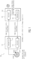
- FIG. 1 illustrates an example of an RF ranging system that employs measuring the time-of-flight to determine the distance between two antennas associated with two radios.
- the system 100 may include a first radio 110 and a second radio 120. These radios may be part of larger objects where the distance between these objects is to be measured. The radios may be integrated into these objects or be part of tags placed on the objects.
- the first radio 110 includes a transmitter 112 and a receiver 114.
- the second radio may include a receiver 124 and a transmitter 122.
- the transmitter 112 in the first radio 110 may transmit a waveform (commonly a chirp or a pulse) that may be received by the receiver 124 at the second radio 120.
- the second radio 120 then processes the received information ("challenge signal") and transmits a response using transmitter 122.
- the response signal is then received by the receiver 114 in the first radio 110.
- the first radio 110 determines the time between transmission and reception of the signals T meas .
- the second radio 120 determines the time it takes the second radio to receive the challenge signal and transmit the response signal T proc .
- the time T proc may be communicated by the second radio 120 to the first radio 110. Alternatively, T proc may also be known by the first radio 110 a priori.
- the communication signal between the two radios may include ultra-wideband pulses.
- Such pulse may be part of a preamble used in the signaling protocol in order to lock onto a signal and to establish communication between the two radios, or the pulses may be the data payload carried by the communication signal. It is also possible to use pulses from both the preamble and the payload data to lock onto the signal. Further, a number of any such pulses may need to be received in order to establish the range between the radios and also to establish a lock on the signal. Once such lock is achieved, the signal payload may then be transmitted.
- the system's performance will be limited by how much the radio signals are degraded as they travel from a transmitter to a receiver.
- Two common sources of degradation are attenuation and reflection due to the radio channel.
- Other sources include interference from other RF systems and thermal noise from various sources.
- a typical radio receiver has a limited dynamic range in terms of the weakest signal it can detect versus the strongest signal it can allow without clipping and distortion.
- the supported signal amplitude range is adapted using automatic gain control (AGC) according to the strongest signal that is present at the receiver. This strategy avoids clipping and overloading of the receiver, but reduces sensitivity to weak signals in the presence of strong signals, which are commonly named blocker signals.
- AGC automatic gain control
- FIG. 2 is a plot of a received communication signal including a weak LOS pulse and a strong reflected pulse.
- AGC automatic gain control
- FIG. 3 illustrates the situation where the receiver sensitivity is set based upon the received stronger reflected pulse for the signal shown in FIG. 2 .
- the sensitivity or the gain is low. Accordingly the noise level is higher as illustrated by the band in the plot.
- the noise completely overcomes the LOS pulse, and hence the LOS pulse is not detected.
- the stronger reflected pulse has an amplitude greater than the noise so it is detected.
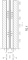
- FIG. 4 illustrates the situation where the receiver sensitivity is increased for the signal shown in FIG. 2 . In this situation the noise level as shown is much lower and the LOS pulse is detectable. Further, because of the increased sensitivity and the dynamic range limits of the receiver, the stronger reflected pulse exceeds the maximum level detectable by the receiver causing the receiver to clip the stronger reflected pulse.
- the embodiments described below seek to set the AGC of the receiver system as shown in FIG. 4 so that LOS pulse can be detected in the presence of a stronger reflected pulse.
- the receiver may use a low gain to first lock onto the preamble part of a packet without overloading, and then intentionally overload once in lock by increasing the gain to search for potential weak pulses preceding the strong pulses. Depending on whether or not such pulses are found, the receiver may switch back to a low gain to avoid overload or stay in the more sensitive mode with high gain to focus on the reception of weaker signals.
- the advantage of this method is that, under the assumption that any relevant weak pulses will appear shortly before large pulses, the receiver can limit its search window.
- FIGs. 5, 6, and 7 illustrate the operation of this first method.
- FIG. 5 illustrates the operation of the first method when a weak LOS pulse and a strong reflected pulse are received.
- a sequence of received pulses is shown below the axis showing the pulses.
- the gain state, lock state, and clipping state for the receiver is shown below the axis showing the pulses.
- the receiver starts in a low gain configuration.
- the receiver locks onto the strong reflected pulse.
- the receiver then may transition into the high gain state.
- this results in the clipping in the receiver when the strong reflected pulse is received.
- the receiver locks onto the weak LOS pulse and the receiver is clipped when the strong reflected pulse is received.
- the receiver continues to operate in the high gain state because it has locked on to a weaker pulse that is received earlier in time, indicating that it is the LOS pulse rather than a reflected pulse.
- FIG. 6 illustrates the operation of the first method when only a weak LOS pulse is received.
- the receiver starts in a low gain configuration. After a few pulses are received and no lock is achieved, the receiver then may transition into the high gain state. Then after a few pulses are received, the receiver locks onto the weak LOS pulse. The receiver continues to operate in the high gain state because it has locked on to a weaker pulse.
- FIG. 7 illustrates the operation of the first method when only strong pulses are received.
- the receiver starts in a low gain configuration.
- the receiver locks onto the strong reflected pulse.
- the receiver then may transition into the high gain state.
- the next pulses are received, this results in the clipping in the receiver.
- the receiver fails to lock onto any pulse and the receiver is clipped when the strong reflected pulse is received, the gain is reduced. Then the receiver locks on to the strong pulse and continues to operate in the low gain state.
- the receiver may start with a high gain or the most sensitive setting of the gain control system, and gate the overload detector (which is basically the signal from the peak detector that normally triggers gain reduction) with a signal indicating successful lock onto a weak pulse train.
- successful lock onto a weak signal would be the condition to prevent the system from reducing receiver sensitivity.
- This method achieves the fastest lock for weak signals, but also puts the toughest requirements on ADC and baseband memory.
- FIGs. 8, 9, and 10 illustrate the operation of this second method.
- FIG. 8 illustrates the operation of the second method when a weak LOS pulse and a strong reflected pulse are received.
- the receiver starts in a high gain configuration. When the first set of pulses are received, the receiver clips the strong reflected pulse. Then when the second set of pulses is received the receiver locks onto the weak LOS pulse and still clips the strong reflected pulse. The receiver continues to operate in the high gain state because it has locked on to a weaker pulse that is received earlier in time, indicating that it is the LOS pulse rather than a reflected pulse.
- FIG. 9 illustrates the operation of the second method when only a weak LOS pulse is received.
- the receiver starts in a high gain configuration. After a few pulses are received, the receiver locks onto the weak LOS pulse. The receiver continues to operate in the high gain state because it has locked on to a pulse and no clipping is indicated so no other potential ranging pulse is present.
- FIG. 10 illustrates the operation of the second method when only strong pulses are received.
- the receiver starts in a high gain configuration.
- the receiver clips the strong reflected pulse. Because the receiver clips the received pulses and no lock is achieved, the receiver may transition into the low gain state. When the next pulse is received, this results in the receiver locking onto the strong reflection pulse, and the receiver stays in the low gain state.
- the weak LOS pulse may still be able to overload the receiver.
- the second method described above would be beneficial, when implemented as a multi-stage gain approach. Again using a lock indicator, the amount of gain reduction that is applied may be limited such that stronger reflections do not affect sensitivity and thereby the Bit Error Rate (BER). In this case, disruption of the distance measurement due to the reflection would also be avoided by this method.
- This third method may be useful in when receiver needs to support a large range of signal amplitudes.
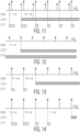
- FIGs. 11, 12, 13, and 14 illustrate the operation of this second method.
- FIG. 11 illustrates the operation of the third method when a medium strength LOS pulse and a strong reflected pulse are received.
- the receiver starts in a high gain configuration.
- the receiver clips both the medium strength LOS pulse and the strong reflected pulse.
- the receiver may transition to a medium gain state.
- the receiver locks onto the medium strength LOS pulse and still clips the strong reflected pulse.
- the receiver continues to operate in the medium gain state because it has locked on to a weaker pulse that is received earlier in time, indicating that it is the LOS pulse rather than a reflected pulse.
- FIG. 12 illustrates the operation of the third method when only a weak LOS pulse is received.
- the receiver starts in a high gain configuration. After a few pulses are received, the receiver locks onto the weak LOS pulse. The receiver continues to operate in the high gain state because it has locked on to a pulse and no clipping is indicated so no other potential ranging pulse is present.
- FIG. 13 illustrates the operation of the third method when only a medium strength LOS pulse is received.
- the receiver starts in a high gain configuration.
- the receiver clips the strong reflected pulse. Because the receiver clips the received pulses and no lock is achieved, the receiver may transition into the medium gain state. After a few pulses are received, the receiver locks onto the medium strength LOS pulse. The receiver continues to operate in the medium gain state because it has locked on to a pulse and no clipping is indicated so no other potential ranging pulse is present.
- FIG. 14 illustrates the operation of the third method when only a strong reflection pulse is received.
- the receiver starts in a high gain configuration.
- the receiver clips the strong reflected pulse. Because the receiver clips the received pulses and no lock is achieved, the receiver may transition into the medium gain state.
- the receiver still clips the strong reflected pulse. Because the receiver clips the received pulses and no lock is achieved, the receiver may transition into the low gain state.
- the receiver locks onto the strong pulse, and the receiver stays in the low gain state.
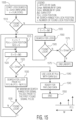
- FIG. 15 illustrates a flow diagram showing the operation of a receiver that starts with a low receiver gain.
- This flow diagram may be used to describe the first method discussed above.
- the receiver starts with a low receiver gain and sets the number of locks to zero 1505. Then the receiver determines if it has locked onto a pulse in the received signal 1510. If so, the receiver increments the number of locks, stores the lock position just found, and stores the gain associated with the found lock position 1515. Next, the receiver then increases the receiver gain 1520. Then the receiver determines if the incremented gain is less than the maximum gain Gmax 1525. If so, then the receiver searches for a lock prior to the current lock 1530. This lock searches back in an interval of time defined by W as shown in FIG. 15 . Next, the receiver determines if a lock is found 1535. If so, then the receiver returns to step 1515. If not, then the receiver returns to step 1520.
- the receiver knows that it has found the lock on the LOS pulse which will be the earliest pulse locked onto.
- the receiver uses the lock at P(n) and set the gain to G(n) 1540.
- the receiver is then ready for payload data 1545, and then ends at 1550.
- the receiver searches for a lock 1560.
- the receiver determines if a lock is found 1565.
- Such lock may be accomplished using a statistical test to detect the presence of a signal. For example, if the noise has a standard deviation ⁇ which corresponds to a noise energy of ⁇ 2 , then a test may be accomplished based upon the noise characteristics.
- the energy of the received signal over a time interval is determined and compared to a threshold C ⁇ 2 to determine if a signal is present.
- the peak of the received signal could be compared to a threshold C ⁇ to determine if a signal is present.
- the value of C is selected to achieve a desired false alarm rate based upon the noise and channel characteristics.
- step 1515 the receiver determines if the incremented gain is less than Gmax. If so, the receiver proceeds to step 1555. If not, then the receiver aborts operation 1575.
- FIG. 16 illustrates a flow diagram showing the operation of a receiver that starts with a high receiver gain. This flow diagram may be used to describe the second and third methods discussed above.
- the receiver starts with a high receiver gain and sets the number of locks to zero 1605. Then the receiver determines if it has clipped a received signal 1610. If so, the receiver searches for a lock 1615. Next, the receiver determines if a lock is found. If so, then the receiver increments the number of locks, stores the lock position just found, and stores the gain associated with the found lock position 1625. Then the receiver decreases the gain 1630. If a lock is not found at step 1620, the receiver proceeds to step 1630 and decreases the gain.
- the receiver determines if the gain is greater than the minimum gain Gmin. If so, the receiver determines if the number of locks is greater than zero 1640. If so, the receiver limits the search area for looking for locks to an interval of time W before the most recent lock as previously described 1645. The receiver then continues to step 1610. If the number of locks is not greater than zero the receiver proceeds to step 1610.
- the receiver determines if the number of locks is greater than zero 1650. If not, then the receiver aborts the method 1670. If the number of locks is greater than zero at step 1650, then the receiver knows that it has found the lock on the LOS pulse which will be the earliest pulse locked onto. The receiver uses the lock at P(n) and set the gain to G(n) 1655. The receiver is then ready for payload data 1660, and then ends at 1665.
- the receiver searches for a lock 1675. The receiver then determines if a lock is found. If so, then, the receiver increments the number of locks, stores the lock position just found, and stores the gain associated with the found lock position 1685. The receiver then proceeds to step 1650. If the receiver does not find a lock at step 1680, then the receiver proceeds to step 1650.
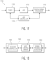
- FIG. 17 illustrates a receiver that implements the methods described above.
- the receiver 1700 may include a tuner 1705, ADC 1710, digital signal processor 1715, and an AGC controller 1720.
- the tuner 1705 tunes the receiver 1700 to a specific frequency to receive an input signal and may convert the received signal to a baseband signal.
- the ADC 1710 receives the baseband signal and samples it to produce a digital signal representing the baseband signal.
- the digital signal processor 1715 receives the digital signal and performs digital signal processing on the digital signal.
- the AGC controller 1720 receives signal information regarding the received signal from the tuner 1705 and the digital signal processor 1715 and also provides AGC control signals to control the AGC applied at the tuner 1705 and the digital signal processor 1715.
- the tuner may include variable/programmable amplifiers (VGAs, PGAs), level detectors, filters, and radio frequency (RF) mixers.
- the amplifiers may be used to set the gain of the receiver 1700 based upon AGC controls. Further, the level detectors may detect the level of the received signal and provide signal level information to the AGC controller.
- the RF mixer may be used to mix the received signal down to a baseband signal.
- the tuner 1705 may include various circuit elements and may be implemented as combination of different integrated circuits (IC), as a single IC, or as a part of a receiver IC.
- the digital signal processor 1715 may include various digital functions, for example, level detectors and a gain function.
- the level detectors may detect the level of the digital signal and provide such level information to the AGC controller 1720.
- the gain function may apply AGC to the digital signal based upon AGC controls from the AGC controller 1720.
- the digital signal processor 1715 may include various circuit elements and may be implemented as a combination of different integrated circuits (IC), as a single IC, as a part of a receiver IC. Further, the digital signal processor may be implemented using executable computer instructions running on a processor.
- the processor may be any type of processor include general purpose processors, signal processors, graphics processors, or application specific ICs (ASICs).
- the AGC controller 1720 implements automatic gain control for the receiver 1700.
- the AGC controller may include various logic and circuits providing AGC control signals to the tuner 1705 and the digital signal processor 1715.
- the AGC controller 1720 may receive level information from the tuner 1705 and the digital signal processor 1715 which may be used to determine the desired gain of the receiver 1700. This desired gain is then communicated to the tuner 1705 and digital signal processor 1715 which is used to adjust the gain and sensitivity of the receiver 1700.
- the AGC controller 1720 may implement the methods of AGC described above for a ranging mode where there is a preference for signals received along the LOS path.
- the ACG control may implement a normal AGC method for a normal communication mode that seeks to lock onto the strongest received signal which may be a reflected signal. Accordingly, the AGC controller may switch between these two modes depending on the needs of the communication system.
- the AGC controller 1720 may include various circuit elements and may be implemented as a combination of different integrated circuits (IC), as a single IC, or as a part of a receiver IC.
- the digital signal processor may be implemented using executable computer instructions running on a processor.
- the processor may be any type of processor include general purpose processors, signal processors, graphics processors, or application specific ICs (ASICs).
- FIG. 18 illustrates an embodiment of the AGC controller.
- the AGC controller 1820 may correspond to the AGC controller 1720 in FIG. 17 .
- the AGC controller 1820 may include a receiver controller 1830, AGC control device 1840, and signal presence detector 1850.
- the receiver controller 1830 may send control signals to the tuner 1705 to control the gain in the tuner and to digital signal processor 1715 to control the processing gain. Further, the receiver controller 1830 may receive level information from the tuner 1705 and the digital signal processor 1715 which may be used to determine the desired gain of the receiver 1700. This desired gain is then communicated to the tuner 1705 and digital signal processor 1715 which is used to adjust the gain and sensitivity of the receiver 1700.
- the signal presence detector 1850 receives an indication from the digital signal processor 1715 that a signal has been detected which them may initiate the AGC algorithms.
- the AGC controller 1820 may implement the methods of AGC described above for a ranging mode where there is a preference for signals received along the LOS path. Also, the ACG controller 1820 may implement a normal AGC method for a normal communication mode that seeks to lock onto the strongest received signal which may be a reflected signal. Accordingly, the AGC controller 1820 may switch between these two modes depending on the needs of the communication system.
- the AGC controller 1820 may include various circuit elements and may be implemented as a combination of different integrated circuits (IC), as a single IC, or as a part of a receiver IC. Further, the digital signal processor may be implemented using executable computer instructions running on a processor.
- the processor may be any type of processor include general purpose processors, signal processors, graphics processors, or application specific ICs (ASICs).
- processor will be understood to encompass a variety of devices such as microprocessors, field-programmable gate arrays (FPGAs), application-specific integrated circuits (ASICs), and other similar processing and computing devices.
- FPGAs field-programmable gate arrays
- ASICs application-specific integrated circuits
Landscapes
- Engineering & Computer Science (AREA)
- Radar, Positioning & Navigation (AREA)
- Remote Sensing (AREA)
- Computer Networks & Wireless Communication (AREA)
- Physics & Mathematics (AREA)
- General Physics & Mathematics (AREA)
- Signal Processing (AREA)
- Circuits Of Receivers In General (AREA)
Claims (15)
- Récepteur (114, 1700), comprenant :un tuner (1705) qui reçoit un signal de communication d'entrée comprenant des impulsions de ligne de visée faibles et des impulsions réfléchies fortes ;un processeur de signal (1715) configuré pour traiter le signal d'entrée ; etun contrôleur de commande automatique de gain, AGC, (1720) configuré pour :initialiser (1505) le récepteur (114, 1700) dans un état de gain faible ;déterminer la présence d'un signal ;augmenter (1520) le gain de récepteur selon un état de gain élevé, pour déterminer si un signal faible est présent avant un signal fort ; etlorsqu'un signal faible est déterminé comme étant présent avant un signal fort :(i) rester dans l'état de gain élevé ; et(ii) lorsque l'écrêtage du signal fort survient dans l'état de gain élevé, rester dans l'état de gain élevé.
- Récepteur (114, 1700) selon la revendication 1, dans lequel le contrôleur AGC (1720) est configuré pour présenter un mode de télémétrie et un mode de communication normale.
- Récepteur (114, 1700) selon la revendication 1, dans lequel la détermination de la présence du signal inclut la détermination (1510) du fait que le récepteur (114, 1700) est verrouillé sur le signal d'entrée.
- Récepteur (114, 1700) selon la revendication 3, comprenant en outre :
l'incrémentation (1515) d'un compteur de verrouillages, qui stocke la position de verrouillage, et qui stocke le gain à cette position de verrouillage. - Récepteur (114, 1700) selon la revendication 4, comprenant en outre :après l'augmentation (1520) du gain de récepteur, la détermination (1525) du fait que le gain de récepteur est inférieur à un gain de récepteur maximum ;la recherche (1530) d'un verrouillage avant le verrouillage courant ;la détermination (1535) du fait qu'un verrouillage est trouvé ; etl'incrémentation encore (1515) d'un compteur de verrouillages, qui stocke la position de verrouillage, et qui stocke le gain à cette position de verrouillage.
- Récepteur (114, 1700) selon la revendication 4, comprenant en outre :après l'augmentation (1520) du gain de récepteur, la détermination (1525) du fait que le gain de récepteur est inférieur à un gain de récepteur maximum ;la recherche (1530) d'un verrouillage avant le verrouillage courant ;la détermination (1535) du fait qu'un verrouillage n'est pas trouvé ; etl'augmentation encore (1520) du gain de récepteur.
- Récepteur (114, 1700) selon la revendication 4, comprenant en outre :après l'augmentation (1520) du gain de récepteur, la détermination du fait que le gain de récepteur n'est pas inférieur à un gain de récepteur maximum ;le verrouillage (1540) du récepteur (114, 1700) sur une position de verrouillage la plus récente et l'instauration du gain de récepteur à un gain de récepteur le plus récent ; etla configuration (1545) du récepteur (114, 1700) pour recevoir des données de charge utile.
- Récepteur (114, 1700) selon la revendication 1, dans lequel la détermination de la présence du signal inclut la détermination (1510) du fait que le récepteur (114, 1700) n'est pas verrouillé sur le signal d'entrée.
- Récepteur (114, 1700) selon la revendication 8, comprenant en outre :après l'augmentation (1555) du gain de récepteur, la recherche (1560) d'un verrouillage ;la détermination (1565) du fait qu'un verrouillage est trouvé ; etl'incrémentation encore (1515) d'un compteur de verrouillages, le stockage de la position de verrouillage, et le stockage du gain à cette position de verrouillage.
- Récepteur (114, 1700) selon la revendication 9, comprenant en outre : l'augmentation encore (1520) du gain de récepteur.
- Récepteur (114, 1700) selon la revendication 8, comprenant en outre :après l'augmentation (1555) du gain de récepteur, la recherche (1560) d'un verrouillage ;la détermination (1565) du fait qu'un verrouillage n'est pas trouvé ; etla détermination (1570) du fait que le gain de récepteur incrémenté n'est pas inférieur à un gain de récepteur maximum.
- Récepteur (114, 1700), comprenant :un tuner (1705) qui reçoit un signal de communication d'entrée comprenant des impulsions de ligne de visée faibles et des impulsions réfléchies fortes ;un processeur de signal (1715) configuré pour traiter le signal d'entrée ; etun contrôleur de commande automatique de gain, AGC, (1720) configuré pour :initialiser (1605) le récepteur (114, 1700) dans un état de gain élevé ;effectuer un verrouillage (1680) sur une partie faible du signal d'entrée lorsque le signal d'entrée inclut une partie de signal forte, dans lequel la partie faible est reçue avant la partie forte ; etmaintenir (1655) le gain de récepteur dans un état de gain élevé pour maintenir le verrouillage sur la partie faible du signal ; etlorsque l'écrêtage du signal fort survient dans l'état de gain élevé, rester dans l'état de gain élevé.
- Récepteur (114, 1700) selon la revendication 12, dans lequel le contrôleur AGC (1720) est configuré pour présenter un mode de télémétrie et un mode de communication normale.
- Récepteur (114, 1700) selon la revendication 12, dans lequel le verrouillage (1680) sur une partie faible du signal d'entrée, lorsque le signal d'entrée inclut une partie de signal forte, inclut la détermination du fait que le récepteur (114, 1700) est en train d'effectuer un écrêtage.
- Récepteur (114, 1700) selon la revendication 14, dans lequel le verrouillage sur une partie faible du signal d'entrée lorsque le signal d'entrée inclut une partie de signal forte inclut en outre :la recherche (1615) d'un verrouillage ;la détermination (1620) du fait qu'un verrouillage est trouvé ;l'incrémentation (1625) d'un compteur de verrouillages, le stockage de la position de verrouillage, et le stockage du gain à cette position de verrouillage ; etla diminution (1630) du gain de récepteur.
Applications Claiming Priority (1)
| Application Number | Priority Date | Filing Date | Title |
|---|---|---|---|
| US14/446,612 US9891311B2 (en) | 2014-07-30 | 2014-07-30 | Method of secure RF ranging under strong multipath reflections |
Publications (2)
| Publication Number | Publication Date |
|---|---|
| EP2980601A1 EP2980601A1 (fr) | 2016-02-03 |
| EP2980601B1 true EP2980601B1 (fr) | 2023-09-13 |
Family
ID=53835888
Family Applications (1)
| Application Number | Title | Priority Date | Filing Date |
|---|---|---|---|
| EP15178725.6A Active EP2980601B1 (fr) | 2014-07-30 | 2015-07-28 | Procédé de télémétrie rf sécurisée sous fortes réflexions à trajets multiples |
Country Status (2)
| Country | Link |
|---|---|
| US (1) | US9891311B2 (fr) |
| EP (1) | EP2980601B1 (fr) |
Families Citing this family (3)
| Publication number | Priority date | Publication date | Assignee | Title |
|---|---|---|---|---|
| US11714183B2 (en) | 2019-09-03 | 2023-08-01 | Nxp B.V. | Impulse radar using variable pulse repetition frequency |
| EP4117243B1 (fr) * | 2020-03-02 | 2026-05-06 | Calterah Semiconductor Technology (Shanghai) Co., Ltd | Procédé de commande automatique de gain, capteur et dispositif radio |
| EP4116735A1 (fr) * | 2021-07-06 | 2023-01-11 | Nxp B.V. | Localisation à consommation d'énergie réduite |
Family Cites Families (12)
| Publication number | Priority date | Publication date | Assignee | Title |
|---|---|---|---|---|
| DE914946C (de) | 1939-03-28 | 1954-07-12 | Atlas Werke Ag | Verfahren und Vorrichtung zur Empfindlichkeitsregelung von Signalempfangsanlagen |
| GB2075300B (en) | 1980-04-30 | 1984-03-07 | Philips Electronic Associated | Method of and apparatus for detecting range pulses for distance measurement |
| US5734974A (en) * | 1996-03-27 | 1998-03-31 | Motorola, Inc. | Selective call receivers with stepwise variable gain control |
| JP4212548B2 (ja) * | 2003-12-26 | 2009-01-21 | 株式会社東芝 | 無線送信装置、無線受信装置、無線送信方法及び無線受信方法 |
| JP2005286806A (ja) * | 2004-03-30 | 2005-10-13 | Nec Corp | 自動利得制御装置および自動利得制御方法 |
| US7187915B2 (en) * | 2004-09-28 | 2007-03-06 | Via Technologies, Inc. | Automatic gain control for a WLAN system |
| US20070197178A1 (en) * | 2006-02-21 | 2007-08-23 | Nokia Corporation | Automatic gain control system for receivers in wireless communications |
| US7978621B2 (en) * | 2007-09-24 | 2011-07-12 | Broadcom Corporation | Power consumption management in a MIMO transceiver and method for use therewith |
| KR101081452B1 (ko) * | 2008-04-14 | 2011-11-09 | 한국전자통신연구원 | 자동 이득 제어기, 그것을 포함한 송수신기, 및 그것의자동 이득 제어 방법 |
| US8886148B2 (en) | 2010-05-26 | 2014-11-11 | Qualcomm Incorporated | Signal based gain control |
| JP5178856B2 (ja) * | 2011-02-16 | 2013-04-10 | 株式会社東芝 | 受信装置 |
| US9057771B2 (en) | 2011-04-25 | 2015-06-16 | Disney Enterprises, Inc. | Carrier sense-based ranging |
-
2014
- 2014-07-30 US US14/446,612 patent/US9891311B2/en active Active
-
2015
- 2015-07-28 EP EP15178725.6A patent/EP2980601B1/fr active Active
Also Published As
| Publication number | Publication date |
|---|---|
| US20160033637A1 (en) | 2016-02-04 |
| EP2980601A1 (fr) | 2016-02-03 |
| US9891311B2 (en) | 2018-02-13 |
Similar Documents
| Publication | Publication Date | Title |
|---|---|---|
| US7129884B1 (en) | Multiple antenna radar signal detection and estimation | |
| EP3048725A2 (fr) | Commande de gain de réception automatique | |
| US8903023B1 (en) | Adaptive bluetooth receiver and method | |
| CN101414847B (zh) | 干扰检测器及干扰检测方法 | |
| US8948311B2 (en) | Receiver and method for determining a time measure depending on a time of arrival of a pulse signal | |
| US20100159854A1 (en) | Method and apparatus for adaptively controlling received power of multi-antenna radio channel measurement equipment | |
| JP6225041B2 (ja) | 受信装置 | |
| JP2000156666A (ja) | キャリア検出回路と通信装置 | |
| EP1795908B1 (fr) | Détection et évaluation des variations de radiofréquence | |
| US9891311B2 (en) | Method of secure RF ranging under strong multipath reflections | |
| KR20150081666A (ko) | 저전력 엔벨로프 검출 수신기에서 간섭 신호를 검출하는 방법 및 장치 | |
| CN116490802A (zh) | 基于啁啾信号的位姿估计方法和装置 | |
| JP2013238477A (ja) | レーダ装置 | |
| CN107872284A (zh) | 无线直放站的自激检测方法及装置 | |
| CN110392387A (zh) | 无线信号的角度测量方法和设备 | |
| US8284095B2 (en) | Radar detection device used in wireless communication device | |
| US20110053535A1 (en) | Wireless communication apparatus | |
| EP4117243B1 (fr) | Procédé de commande automatique de gain, capteur et dispositif radio | |
| US20040192242A1 (en) | Method and apparatus to acquire frame within transmission | |
| JP3853713B2 (ja) | 送信パルスのレベル補正回路と補正方法、及びそれを用いたdme装置の応答機 | |
| US10277263B2 (en) | Radio receiver | |
| KR20180094319A (ko) | 자동 이득 제어 장치 및 방법 | |
| US8676147B1 (en) | Detection system, controller, and method of detecting a signal of interest | |
| WO2014049907A1 (fr) | Dispositif de transmission sans fil, dispositif de détermination de vswr, et procédé de détermination de vswr | |
| KR101489890B1 (ko) | 통신 시스템에서 동기신호 처리 방법 |
Legal Events
| Date | Code | Title | Description |
|---|---|---|---|
| PUAI | Public reference made under article 153(3) epc to a published international application that has entered the european phase |
Free format text: ORIGINAL CODE: 0009012 |
|
| AK | Designated contracting states |
Kind code of ref document: A1 Designated state(s): AL AT BE BG CH CY CZ DE DK EE ES FI FR GB GR HR HU IE IS IT LI LT LU LV MC MK MT NL NO PL PT RO RS SE SI SK SM TR |
|
| AX | Request for extension of the european patent |
Extension state: BA ME |
|
| 17P | Request for examination filed |
Effective date: 20160803 |
|
| RBV | Designated contracting states (corrected) |
Designated state(s): AL AT BE BG CH CY CZ DE DK EE ES FI FR GB GR HR HU IE IS IT LI LT LU LV MC MK MT NL NO PL PT RO RS SE SI SK SM TR |
|
| STAA | Information on the status of an ep patent application or granted ep patent |
Free format text: STATUS: EXAMINATION IS IN PROGRESS |
|
| 17Q | First examination report despatched |
Effective date: 20180713 |
|
| GRAP | Despatch of communication of intention to grant a patent |
Free format text: ORIGINAL CODE: EPIDOSNIGR1 |
|
| STAA | Information on the status of an ep patent application or granted ep patent |
Free format text: STATUS: GRANT OF PATENT IS INTENDED |
|
| INTG | Intention to grant announced |
Effective date: 20230515 |
|
| GRAS | Grant fee paid |
Free format text: ORIGINAL CODE: EPIDOSNIGR3 |
|
| GRAA | (expected) grant |
Free format text: ORIGINAL CODE: 0009210 |
|
| STAA | Information on the status of an ep patent application or granted ep patent |
Free format text: STATUS: THE PATENT HAS BEEN GRANTED |
|
| AK | Designated contracting states |
Kind code of ref document: B1 Designated state(s): AL AT BE BG CH CY CZ DE DK EE ES FI FR GB GR HR HU IE IS IT LI LT LU LV MC MK MT NL NO PL PT RO RS SE SI SK SM TR |
|
| REG | Reference to a national code |
Ref country code: GB Ref legal event code: FG4D |
|
| REG | Reference to a national code |
Ref country code: CH Ref legal event code: EP |
|
| REG | Reference to a national code |
Ref country code: DE Ref legal event code: R096 Ref document number: 602015085670 Country of ref document: DE |
|
| REG | Reference to a national code |
Ref country code: IE Ref legal event code: FG4D |
|
| REG | Reference to a national code |
Ref country code: LT Ref legal event code: MG9D |
|
| REG | Reference to a national code |
Ref country code: NL Ref legal event code: MP Effective date: 20230913 |
|
| PG25 | Lapsed in a contracting state [announced via postgrant information from national office to epo] |
Ref country code: GR Free format text: LAPSE BECAUSE OF FAILURE TO SUBMIT A TRANSLATION OF THE DESCRIPTION OR TO PAY THE FEE WITHIN THE PRESCRIBED TIME-LIMIT Effective date: 20231214 |
|
| PG25 | Lapsed in a contracting state [announced via postgrant information from national office to epo] |
Ref country code: SE Free format text: LAPSE BECAUSE OF FAILURE TO SUBMIT A TRANSLATION OF THE DESCRIPTION OR TO PAY THE FEE WITHIN THE PRESCRIBED TIME-LIMIT Effective date: 20230913 Ref country code: RS Free format text: LAPSE BECAUSE OF FAILURE TO SUBMIT A TRANSLATION OF THE DESCRIPTION OR TO PAY THE FEE WITHIN THE PRESCRIBED TIME-LIMIT Effective date: 20230913 Ref country code: NO Free format text: LAPSE BECAUSE OF FAILURE TO SUBMIT A TRANSLATION OF THE DESCRIPTION OR TO PAY THE FEE WITHIN THE PRESCRIBED TIME-LIMIT Effective date: 20231213 Ref country code: LV Free format text: LAPSE BECAUSE OF FAILURE TO SUBMIT A TRANSLATION OF THE DESCRIPTION OR TO PAY THE FEE WITHIN THE PRESCRIBED TIME-LIMIT Effective date: 20230913 Ref country code: LT Free format text: LAPSE BECAUSE OF FAILURE TO SUBMIT A TRANSLATION OF THE DESCRIPTION OR TO PAY THE FEE WITHIN THE PRESCRIBED TIME-LIMIT Effective date: 20230913 Ref country code: HR Free format text: LAPSE BECAUSE OF FAILURE TO SUBMIT A TRANSLATION OF THE DESCRIPTION OR TO PAY THE FEE WITHIN THE PRESCRIBED TIME-LIMIT Effective date: 20230913 Ref country code: GR Free format text: LAPSE BECAUSE OF FAILURE TO SUBMIT A TRANSLATION OF THE DESCRIPTION OR TO PAY THE FEE WITHIN THE PRESCRIBED TIME-LIMIT Effective date: 20231214 Ref country code: FI Free format text: LAPSE BECAUSE OF FAILURE TO SUBMIT A TRANSLATION OF THE DESCRIPTION OR TO PAY THE FEE WITHIN THE PRESCRIBED TIME-LIMIT Effective date: 20230913 |
|
| REG | Reference to a national code |
Ref country code: AT Ref legal event code: MK05 Ref document number: 1611816 Country of ref document: AT Kind code of ref document: T Effective date: 20230913 |
|
| PG25 | Lapsed in a contracting state [announced via postgrant information from national office to epo] |
Ref country code: NL Free format text: LAPSE BECAUSE OF FAILURE TO SUBMIT A TRANSLATION OF THE DESCRIPTION OR TO PAY THE FEE WITHIN THE PRESCRIBED TIME-LIMIT Effective date: 20230913 |
|
| P01 | Opt-out of the competence of the unified patent court (upc) registered |
Effective date: 20240228 |
|
| PG25 | Lapsed in a contracting state [announced via postgrant information from national office to epo] |
Ref country code: IS Free format text: LAPSE BECAUSE OF FAILURE TO SUBMIT A TRANSLATION OF THE DESCRIPTION OR TO PAY THE FEE WITHIN THE PRESCRIBED TIME-LIMIT Effective date: 20240113 |
|
| PG25 | Lapsed in a contracting state [announced via postgrant information from national office to epo] |
Ref country code: AT Free format text: LAPSE BECAUSE OF FAILURE TO SUBMIT A TRANSLATION OF THE DESCRIPTION OR TO PAY THE FEE WITHIN THE PRESCRIBED TIME-LIMIT Effective date: 20230913 |
|
| PG25 | Lapsed in a contracting state [announced via postgrant information from national office to epo] |
Ref country code: ES Free format text: LAPSE BECAUSE OF FAILURE TO SUBMIT A TRANSLATION OF THE DESCRIPTION OR TO PAY THE FEE WITHIN THE PRESCRIBED TIME-LIMIT Effective date: 20230913 |
|
| PG25 | Lapsed in a contracting state [announced via postgrant information from national office to epo] |
Ref country code: SM Free format text: LAPSE BECAUSE OF FAILURE TO SUBMIT A TRANSLATION OF THE DESCRIPTION OR TO PAY THE FEE WITHIN THE PRESCRIBED TIME-LIMIT Effective date: 20230913 Ref country code: RO Free format text: LAPSE BECAUSE OF FAILURE TO SUBMIT A TRANSLATION OF THE DESCRIPTION OR TO PAY THE FEE WITHIN THE PRESCRIBED TIME-LIMIT Effective date: 20230913 Ref country code: IS Free format text: LAPSE BECAUSE OF FAILURE TO SUBMIT A TRANSLATION OF THE DESCRIPTION OR TO PAY THE FEE WITHIN THE PRESCRIBED TIME-LIMIT Effective date: 20240113 Ref country code: ES Free format text: LAPSE BECAUSE OF FAILURE TO SUBMIT A TRANSLATION OF THE DESCRIPTION OR TO PAY THE FEE WITHIN THE PRESCRIBED TIME-LIMIT Effective date: 20230913 Ref country code: EE Free format text: LAPSE BECAUSE OF FAILURE TO SUBMIT A TRANSLATION OF THE DESCRIPTION OR TO PAY THE FEE WITHIN THE PRESCRIBED TIME-LIMIT Effective date: 20230913 Ref country code: CZ Free format text: LAPSE BECAUSE OF FAILURE TO SUBMIT A TRANSLATION OF THE DESCRIPTION OR TO PAY THE FEE WITHIN THE PRESCRIBED TIME-LIMIT Effective date: 20230913 Ref country code: AT Free format text: LAPSE BECAUSE OF FAILURE TO SUBMIT A TRANSLATION OF THE DESCRIPTION OR TO PAY THE FEE WITHIN THE PRESCRIBED TIME-LIMIT Effective date: 20230913 Ref country code: PT Free format text: LAPSE BECAUSE OF FAILURE TO SUBMIT A TRANSLATION OF THE DESCRIPTION OR TO PAY THE FEE WITHIN THE PRESCRIBED TIME-LIMIT Effective date: 20240115 Ref country code: SK Free format text: LAPSE BECAUSE OF FAILURE TO SUBMIT A TRANSLATION OF THE DESCRIPTION OR TO PAY THE FEE WITHIN THE PRESCRIBED TIME-LIMIT Effective date: 20230913 |
|
| PG25 | Lapsed in a contracting state [announced via postgrant information from national office to epo] |
Ref country code: PL Free format text: LAPSE BECAUSE OF FAILURE TO SUBMIT A TRANSLATION OF THE DESCRIPTION OR TO PAY THE FEE WITHIN THE PRESCRIBED TIME-LIMIT Effective date: 20230913 Ref country code: IT Free format text: LAPSE BECAUSE OF FAILURE TO SUBMIT A TRANSLATION OF THE DESCRIPTION OR TO PAY THE FEE WITHIN THE PRESCRIBED TIME-LIMIT Effective date: 20230913 |
|
| REG | Reference to a national code |
Ref country code: DE Ref legal event code: R097 Ref document number: 602015085670 Country of ref document: DE |
|
| PG25 | Lapsed in a contracting state [announced via postgrant information from national office to epo] |
Ref country code: DK Free format text: LAPSE BECAUSE OF FAILURE TO SUBMIT A TRANSLATION OF THE DESCRIPTION OR TO PAY THE FEE WITHIN THE PRESCRIBED TIME-LIMIT Effective date: 20230913 |
|
| PLBE | No opposition filed within time limit |
Free format text: ORIGINAL CODE: 0009261 |
|
| STAA | Information on the status of an ep patent application or granted ep patent |
Free format text: STATUS: NO OPPOSITION FILED WITHIN TIME LIMIT |
|
| PG25 | Lapsed in a contracting state [announced via postgrant information from national office to epo] |
Ref country code: DK Free format text: LAPSE BECAUSE OF FAILURE TO SUBMIT A TRANSLATION OF THE DESCRIPTION OR TO PAY THE FEE WITHIN THE PRESCRIBED TIME-LIMIT Effective date: 20230913 |
|
| 26N | No opposition filed |
Effective date: 20240614 |
|
| PG25 | Lapsed in a contracting state [announced via postgrant information from national office to epo] |
Ref country code: SI Free format text: LAPSE BECAUSE OF FAILURE TO SUBMIT A TRANSLATION OF THE DESCRIPTION OR TO PAY THE FEE WITHIN THE PRESCRIBED TIME-LIMIT Effective date: 20230913 |
|
| PG25 | Lapsed in a contracting state [announced via postgrant information from national office to epo] |
Ref country code: SI Free format text: LAPSE BECAUSE OF FAILURE TO SUBMIT A TRANSLATION OF THE DESCRIPTION OR TO PAY THE FEE WITHIN THE PRESCRIBED TIME-LIMIT Effective date: 20230913 |
|
| PG25 | Lapsed in a contracting state [announced via postgrant information from national office to epo] |
Ref country code: BG Free format text: LAPSE BECAUSE OF FAILURE TO SUBMIT A TRANSLATION OF THE DESCRIPTION OR TO PAY THE FEE WITHIN THE PRESCRIBED TIME-LIMIT Effective date: 20230913 |
|
| PG25 | Lapsed in a contracting state [announced via postgrant information from national office to epo] |
Ref country code: BG Free format text: LAPSE BECAUSE OF FAILURE TO SUBMIT A TRANSLATION OF THE DESCRIPTION OR TO PAY THE FEE WITHIN THE PRESCRIBED TIME-LIMIT Effective date: 20230913 |
|
| PG25 | Lapsed in a contracting state [announced via postgrant information from national office to epo] |
Ref country code: MC Free format text: LAPSE BECAUSE OF FAILURE TO SUBMIT A TRANSLATION OF THE DESCRIPTION OR TO PAY THE FEE WITHIN THE PRESCRIBED TIME-LIMIT Effective date: 20230913 |
|
| REG | Reference to a national code |
Ref country code: CH Ref legal event code: PL |
|
| PG25 | Lapsed in a contracting state [announced via postgrant information from national office to epo] |
Ref country code: LU Free format text: LAPSE BECAUSE OF NON-PAYMENT OF DUE FEES Effective date: 20240728 |
|
| GBPC | Gb: european patent ceased through non-payment of renewal fee |
Effective date: 20240728 |
|
| PG25 | Lapsed in a contracting state [announced via postgrant information from national office to epo] |
Ref country code: LU Free format text: LAPSE BECAUSE OF NON-PAYMENT OF DUE FEES Effective date: 20240728 |
|
| PG25 | Lapsed in a contracting state [announced via postgrant information from national office to epo] |
Ref country code: BE Free format text: LAPSE BECAUSE OF NON-PAYMENT OF DUE FEES Effective date: 20240731 Ref country code: CH Free format text: LAPSE BECAUSE OF NON-PAYMENT OF DUE FEES Effective date: 20240731 |
|
| PG25 | Lapsed in a contracting state [announced via postgrant information from national office to epo] |
Ref country code: GB Free format text: LAPSE BECAUSE OF NON-PAYMENT OF DUE FEES Effective date: 20240728 |
|
| REG | Reference to a national code |
Ref country code: BE Ref legal event code: MM Effective date: 20240731 |
|
| PGFP | Annual fee paid to national office [announced via postgrant information from national office to epo] |
Ref country code: FR Payment date: 20250620 Year of fee payment: 11 |
|
| PG25 | Lapsed in a contracting state [announced via postgrant information from national office to epo] |
Ref country code: IE Free format text: LAPSE BECAUSE OF NON-PAYMENT OF DUE FEES Effective date: 20240728 |
|
| PGFP | Annual fee paid to national office [announced via postgrant information from national office to epo] |
Ref country code: DE Payment date: 20250620 Year of fee payment: 11 |
|
| PG25 | Lapsed in a contracting state [announced via postgrant information from national office to epo] |
Ref country code: CY Free format text: LAPSE BECAUSE OF FAILURE TO SUBMIT A TRANSLATION OF THE DESCRIPTION OR TO PAY THE FEE WITHIN THE PRESCRIBED TIME-LIMIT; INVALID AB INITIO Effective date: 20150728 |
|
| PG25 | Lapsed in a contracting state [announced via postgrant information from national office to epo] |
Ref country code: HU Free format text: LAPSE BECAUSE OF FAILURE TO SUBMIT A TRANSLATION OF THE DESCRIPTION OR TO PAY THE FEE WITHIN THE PRESCRIBED TIME-LIMIT; INVALID AB INITIO Effective date: 20150728 |