EP2980657A1 - Kartusche, bilderzeugende vorrichtung und verfahren zur montage der kartusche auf einer bilderzeugenden vorrichtung - Google Patents
Kartusche, bilderzeugende vorrichtung und verfahren zur montage der kartusche auf einer bilderzeugenden vorrichtung Download PDFInfo
- Publication number
- EP2980657A1 EP2980657A1 EP15178775.1A EP15178775A EP2980657A1 EP 2980657 A1 EP2980657 A1 EP 2980657A1 EP 15178775 A EP15178775 A EP 15178775A EP 2980657 A1 EP2980657 A1 EP 2980657A1
- Authority
- EP
- European Patent Office
- Prior art keywords
- cartridge
- gear
- protruding portion
- image forming
- forming apparatus
- Prior art date
- Legal status (The legal status is an assumption and is not a legal conclusion. Google has not performed a legal analysis and makes no representation as to the accuracy of the status listed.)
- Withdrawn
Links
- 238000000034 method Methods 0.000 title claims description 15
- 230000032258 transport Effects 0.000 claims abstract description 17
- 238000000926 separation method Methods 0.000 claims abstract description 8
- 238000012546 transfer Methods 0.000 claims description 73
- 108091008695 photoreceptors Proteins 0.000 claims description 44
- 238000003780 insertion Methods 0.000 claims description 7
- 230000037431 insertion Effects 0.000 claims description 7
- 238000011144 upstream manufacturing Methods 0.000 description 8
- 230000007246 mechanism Effects 0.000 description 7
- 230000008569 process Effects 0.000 description 7
- 238000013461 design Methods 0.000 description 5
- 239000000843 powder Substances 0.000 description 5
- 238000007599 discharging Methods 0.000 description 4
- 238000005549 size reduction Methods 0.000 description 4
- 230000006835 compression Effects 0.000 description 3
- 238000007906 compression Methods 0.000 description 3
- 238000010586 diagram Methods 0.000 description 2
- 230000035939 shock Effects 0.000 description 2
- 230000008901 benefit Effects 0.000 description 1
- 230000000694 effects Effects 0.000 description 1
- 230000012447 hatching Effects 0.000 description 1
- 238000012986 modification Methods 0.000 description 1
- 230000004048 modification Effects 0.000 description 1
- 230000002093 peripheral effect Effects 0.000 description 1
- 230000000007 visual effect Effects 0.000 description 1
Images



Classifications
-
- G—PHYSICS
- G03—PHOTOGRAPHY; CINEMATOGRAPHY; ANALOGOUS TECHNIQUES USING WAVES OTHER THAN OPTICAL WAVES; ELECTROGRAPHY; HOLOGRAPHY
- G03G—ELECTROGRAPHY; ELECTROPHOTOGRAPHY; MAGNETOGRAPHY
- G03G15/00—Apparatus for electrographic processes using a charge pattern
- G03G15/06—Apparatus for electrographic processes using a charge pattern for developing
- G03G15/08—Apparatus for electrographic processes using a charge pattern for developing using a solid developer, e.g. powder developer
- G03G15/0822—Arrangements for preparing, mixing, supplying or dispensing developer
- G03G15/0865—Arrangements for supplying new developer
- G03G15/0867—Arrangements for supplying new developer cylindrical developer cartridges, e.g. toner bottles for the developer replenishing opening
-
- G—PHYSICS
- G03—PHOTOGRAPHY; CINEMATOGRAPHY; ANALOGOUS TECHNIQUES USING WAVES OTHER THAN OPTICAL WAVES; ELECTROGRAPHY; HOLOGRAPHY
- G03G—ELECTROGRAPHY; ELECTROPHOTOGRAPHY; MAGNETOGRAPHY
- G03G21/00—Arrangements not provided for by groups G03G13/00 - G03G19/00, e.g. cleaning, elimination of residual charge
- G03G21/16—Mechanical means for facilitating the maintenance of the apparatus, e.g. modular arrangements
- G03G21/18—Mechanical means for facilitating the maintenance of the apparatus, e.g. modular arrangements using a processing cartridge, whereby the process cartridge comprises at least two image processing means in a single unit
-
- G—PHYSICS
- G03—PHOTOGRAPHY; CINEMATOGRAPHY; ANALOGOUS TECHNIQUES USING WAVES OTHER THAN OPTICAL WAVES; ELECTROGRAPHY; HOLOGRAPHY
- G03G—ELECTROGRAPHY; ELECTROPHOTOGRAPHY; MAGNETOGRAPHY
- G03G21/00—Arrangements not provided for by groups G03G13/00 - G03G19/00, e.g. cleaning, elimination of residual charge
- G03G21/16—Mechanical means for facilitating the maintenance of the apparatus, e.g. modular arrangements
- G03G21/18—Mechanical means for facilitating the maintenance of the apparatus, e.g. modular arrangements using a processing cartridge, whereby the process cartridge comprises at least two image processing means in a single unit
- G03G21/1839—Means for handling the process cartridge in the apparatus body
- G03G21/1857—Means for handling the process cartridge in the apparatus body for transmitting mechanical drive power to the process cartridge, drive mechanisms, gears, couplings, braking mechanisms
- G03G21/1864—Means for handling the process cartridge in the apparatus body for transmitting mechanical drive power to the process cartridge, drive mechanisms, gears, couplings, braking mechanisms associated with a positioning function
-
- G—PHYSICS
- G03—PHOTOGRAPHY; CINEMATOGRAPHY; ANALOGOUS TECHNIQUES USING WAVES OTHER THAN OPTICAL WAVES; ELECTROGRAPHY; HOLOGRAPHY
- G03G—ELECTROGRAPHY; ELECTROPHOTOGRAPHY; MAGNETOGRAPHY
- G03G15/00—Apparatus for electrographic processes using a charge pattern
- G03G15/06—Apparatus for electrographic processes using a charge pattern for developing
- G03G15/08—Apparatus for electrographic processes using a charge pattern for developing using a solid developer, e.g. powder developer
- G03G15/0822—Arrangements for preparing, mixing, supplying or dispensing developer
- G03G15/0865—Arrangements for supplying new developer
-
- G—PHYSICS
- G03—PHOTOGRAPHY; CINEMATOGRAPHY; ANALOGOUS TECHNIQUES USING WAVES OTHER THAN OPTICAL WAVES; ELECTROGRAPHY; HOLOGRAPHY
- G03G—ELECTROGRAPHY; ELECTROPHOTOGRAPHY; MAGNETOGRAPHY
- G03G21/00—Arrangements not provided for by groups G03G13/00 - G03G19/00, e.g. cleaning, elimination of residual charge
- G03G21/16—Mechanical means for facilitating the maintenance of the apparatus, e.g. modular arrangements
- G03G21/18—Mechanical means for facilitating the maintenance of the apparatus, e.g. modular arrangements using a processing cartridge, whereby the process cartridge comprises at least two image processing means in a single unit
- G03G21/1839—Means for handling the process cartridge in the apparatus body
- G03G21/1842—Means for handling the process cartridge in the apparatus body for guiding and mounting the process cartridge, positioning, alignment, locks
Definitions
- the present invention generally relates to a cartridge, an image forming apparatus with the cartridge, and a method for mounting the cartridge to the image forming apparatus.
- a photoreceptor roller also called a photoreceptor drum
- a toner image is formed by adhering toner to the electrostatic latent image formed on the photoreceptor roller by using a developing roller.
- the toner image is transferred to a recording medium by a transfer roller provided facing the photoreceptor roller.
- the developing roller and photoreceptor roller are included in the cartridge detachable from the printer. Therefore, it is necessary to transfer power for rotating the developing roller and the photoreceptor roller from the driving source to the cartridge.
- a gear is used for transferring power to a cartridge. Specifically, with the cartridge mounted on the printer, a first gear provided on the printer engages with a second gear provided on the cartridge.
- a guiderail guides the movement of the cartridge so that the first gear and the second gear do not come in contact and become damaged when the cartridge is being mounted onto the printer.
- Patent Document 1 when a guiderail is provided on the inner side face of the printer, the flexibility of the design of the printer is reduced. Moreover, the location of the contact terminal of the printer and the cartridge, or the location of the transferring member for transferring power to the cartridge is limited by the guiderail provided on the inner side face of the printer. Furthermore, the width of the printer may increase by the guiderail provided on the inner side face of the printer.
- a printer according to one or more embodiments of the present invention can suppress the lowering of flexibility in design by a mechanism for assisting the detaching of the cartridge to the printer.
- a printer may comprise a cartridge having a developing powder, provided with a mounting face with a transfer roller exposed in a position opposing a photoreceptor roller included in the cartridge, a first gear engaging a second gear included in the cartridge, the second gear being connected to the photoreceptor roller, and at least one protruding portion protruding from the mounting face, the at least one protruding portion restricting the distance between the first gear and the second gear in a direction crossing the mounting face by contacting the cartridge when the cartridge proceeds in a direction crossing the axis direction of the transfer roller until a position where the first gear and the second gear engage when the cartridge is mounted to the printer.
- the distance between the first gear and the second gear during the progression of the cartridge may be restricted by the protruding portion protruding from the mounting face. That is, the first gear and the second gear can be separated in a direction crossing the mounting face so that the first gear and second gear do not contact when the cartridge is proceeding. Therefore, the attaching and/or detaching of the cartridge to the printer can appropriately be assisted and the lowering of the flexibility in design of the printer can be suppressed even if there is no mechanism provided on the inner side face of the printer for preventing the contact of the first gear and the second gear.
- the at least one protruding portion may be provided between the transfer roller and the first gear in the axis direction of the transfer roller.
- the protruding portion can be provided between the transfer roller and the first gear in the axis direction of the transfer roller. Therefore, the protruding portion can be disposed in a region where a bearing of the transfer roller is disposed, or a region arranged in a direction that crosses the axis direction of that region and the transfer roller. As a result, the dimensions of the printer in the axis direction of the transfer roller can be reduced, thereby contributing to the size reduction of the printer.
- the at least one protruding portion may rotatably hold the transfer roller and may include a first protruding portion protruding from the mounting face and a second protruding portion protruding from the mounting face, being provided arranged with the first protruding portion in a direction crossing the axis direction of the transfer roller on the mounting face.
- the protruding portion can rotatably hold the transfer roller. That is to say, that a bearing of the transfer roller can be used as the protruding portion for restricting the distance between the first gear and the second gear. Therefore, the length of the second protruding portion in a direction crossing the axis direction of the transfer roller can be reduced on the mounting face, thereby contributing to the size reduction of the printer.
- the first protruding portion may have elasticity in a direction crossing the mounting face.
- the first protruding portion can have elasticity in a direction crossing the mounting face. Therefore, shock can be alleviated when the cartridge contacts the protruding portion, and the occurrence of damage to the printer and the cartridge can be reduced.
- the at least one protruding portion may engage with an engaging portion formed on the cartridge in a direction crossing the axis direction of the transfer roller on the mounting face with the cartridge mounted to the printer.
- the protruding portion of the printer and the engaging portion of the cartridge can be engaged in a direction crossing the axis direction of the transfer roller on the mounting face. Therefore, the protruding portion for restricting the distance between the first gear and the second gear when the cartridge is being mounted can be used as a mechanism for restricting the movement of the cartridge after the cartridge has been mounted.
- an image forming apparatus that uses a cartridge, may comprise a protruding portion that engages with an engaging portion of the cartridge; and a first gear that engages with a second gear of the cartridge, wherein while the cartridge is being inserted into the image forming apparatus, the protruding portion may maintain a distance of separation, between the first gear and the second gear in a direction crossing a face that transports a recording medium, until the protruding portion engages with the engaging portion.
- a cartridge mounted on an image forming apparatus may comprises an engaging portion that engages with a protruding portion of the image forming apparatus; a second gear that engages with a first gear of the image forming apparatus, wherein while the cartridge is being inserted into the image forming apparatus, the engaging portion may maintain a distance of separation, between the first gear and the second gear in a direction crossing a face that transports a recording medium, until the engaging portion engages with the protruding portion.
- a method for mounting a cartridge to an image forming apparatus may comprise inserting the cartridge into the image forming apparatus; engaging a first engaging portion of the image forming apparatus with a second engaging portion of the cartridge; and engaging a first gear included in the image forming apparatus with a second gear of the cartridge, wherein at least one of the first engaging portion and the second engaging portion protrudes in a direction crossing a face that transports a recording medium; and while the cartridge is being inserted into the image forming apparatus, maintaining a distance of separation between the first gear and the second gear in the direction crossing the face that transports the recording medium, until the first engaging portion engages with the second engaging portion.
- the image forming apparatus comprises a transfer roller, and the first engaging portion is disposed between the transfer roller and the first gear in an axis direction of the transfer roller.
- the first engaging portion is disposed further downstream than the first gear in a transporting direction of the recording medium.
- the cartridge comprises a photoreceptor roller, the second gear connects to the photoreceptor roller, and the photoreceptor roller rotates by the first gear and the second gear engaging.
- the second engaging portion is disposed further downstream than the photoreceptor roller along a transporting direction of the recording medium and toward an insertion direction of the cartridge.
- the image forming apparatus comprises a transfer roller
- the at least one of the first engaging portion and the second engaging portion comprises: a first portion that rotatably holds the transfer roller and protrudes from the face, and a second portion that is arranged with the first portion in a direction crossing an axis direction of the transfer roller and protrudes from the face.
- the first portion has elasticity in a direction crossing the face.
- the printer according to one or more embodiments of the present invention can suppress the lowering of the flexibility in design by a mechanism for supporting the attaching and detaching of the cartridge to the printer.
- a printer may be a printer that can attach/detach a cartridge having a developing powder, and is characterized by the removing mechanism of the cartridge.
- a printer is an example of an image forming apparatus.
- the image forming apparatus may be the printer or an MFP (Multi-Function Peripheral) which includes a printing function.
- MFP Multi-Function Peripheral
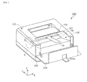
- FIG. 1 is a perspective view illustrating the printer 100 according to one or more embodiments of the first example of the present invention.
- an X-axis direction is an axis direction of the transfer roller 107 included in the printer 100.
- a side away from the printer 100 in the axis direction of the transfer roller 107 will be referred to as an outside in the axis direction of the transfer roller 107.
- a side approaching a center of the axis of the transfer roller 107 will be referred to as an inside in the axis direction of the transfer roller 107.
- a Y-axis direction is a direction that crosses the X-axis direction and a direction to which a recording medium is transported (hereinafter transporting direction).
- a positive side and negative side of the Y-axis will be referred to as a downstream side of the transporting direction and an upstream side of the transporting direction, respectively.
- a Z-axis direction is a direction that crosses the X-axis and the Y-axis.
- a positive side and negative side of the Z-axis will be referred to as the upper side and the lower side.
- the printer 100 may be, for example, a laser printer.
- the printer 100 may comprise a housing 101, a paper feeding cassette 102, a paper discharging tray 103, and a front cover 104 as illustrated in FIG. 1 .
- the paper feeding cassette 102 is provided on a lower portion of the housing 101, and is housed in the housing 101 drawable in the Y-axis direction.
- the paper feeding cassette 102 stores a recording medium which is sheet-shaped (for example, paper).
- the paper discharging tray 103 is provided on the upper face of the housing 101.
- the recording medium to be printed is discharged from the paper discharging tray 103.
- the front cover 104 is a member configuring one portion of the housing 101.
- the front cover 104 covers one portion of the upper face and one portion of the front face of the housing 101 so as to freely open and close.
- a user can open the front cover 104 by raising a handle portion 104a provided movably on the upper face of the front cover 104 and pulling in the upstream side of the transporting direction (the negative side of the Y-axis).
- FIG. 2 is a perspective view of the front cover 104 of the printer 100 according to one or more embodiments of the first example of the present invention opened.
- an insertion opening 105 is exposed for detaching a cartridge 200 described hereafter.
- the cartridge 200 is mounted to the printer 100 by inserting in a direction of arrow 10 (Y-axis direction) into the insertion opening 105. Furthermore, the cartridge 200 mounted to the printer 100 is removed from the printer 100 by pulling in the direction opposite the arrow 10 from the insertion opening 105.
- FIG. 2 is a perspective view of a portion to which the cartridge 200 is mounted of the printer 100 according to one or more embodiments of the first example of the present invention. Specifically, FIG. 2 is a perspective view when viewing portion A in FIG. 1 from a different direction from that of FIG. 1 .
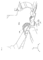
- FIG. 3 is an enlarged perspective view of the vicinity of a protruding portion 109 included in the printer 100 according to one or more embodiments of the first example of the present invention.
- the printer 100 may internally comprise a mounting face 106, a transfer roller 107, a first gear 108, and a protruding portion 109.
- the mounting face 106 is a face with the cartridge 200 mounted. Specifically, the mounting face 106 is a face substantially parallel to the XY plane. Here, the recording medium is transported in the Y-axis direction on the mounting face 106.
- the XY plane is a face that transports the recording medium.
- the transfer roller 107 is exposed on the mounting face 106 in a position opposing a photoreceptor roller 201 (described hereafter) included in the cartridge 200.
- a photoreceptor roller 201 (described hereafter) included in the cartridge 200.
- the transfer roller 107 and the photoreceptor roller 201 face each other when the cartridge 200 is mounted to the printer 100.
- the transfer roller 107 extends in the X-axis direction and is rotatably held around the X-axis. By rotating in the opposite direction of the photoreceptor roller 201, the transfer roller 107 transfers a visible image formed on the surface of the photoreceptor roller 201 to the recording medium that passes in the Y-axis direction between the transfer roller 107 and the photoreceptor roller 201.
- the first gear 108 engages a second gear 202 (described hereafter) connected to the photoreceptor roller 201 included in the cartridge 200.
- the first gear 108 rotates by a driving source (not illustrated) and communicates rotational force to the photoreceptor roller 201 via the second gear 202.
- the first gear 108 is disposed separated from the transfer roller 107 in the axis direction of the transfer roller 107 (X-axis direction). Specifically, the first gear 108 is attached to a side frame 101a disposed separated from the transfer roller 107 in the X-axis direction.
- the protruding portion 109 restricts the distance between the first gear 108 and the second gear 202 in a direction crossing the mounting face 106 (a direction crossing the face that transports a recording medium) (Z-axis direction) by contacting the cartridge 200 when the cartridge 200 proceeds in a direction crossing the axis direction of the transfer roller 107 (Y-axis) until a position where the first gear 108 and the second gear 202 engage when the cartridge 200 is mounted to the printer 100.
- the protruding portion 109 maintains the disconnected state of the first gear 108 and the second 202 during the progression of the cartridge 200.
- the protruding portion 109 separates the first gear 108 and the second gear 202 in the Z-axis direction when the cartridge 200 is inserted to the printer 100.
- the protruding portion 109 maintains a distance of separation between the first gear 108 and the second gear 202 in the direction crossing the face that transports a recording medium until the protruding portion 109 engages with the engaging portion 203 and contacts the cartridge 200.
- the protruding portion 109 is disposed between the transfer roller 107 and the first gear 108 in the axis direction of the transfer roller 107 (X-axis direction).
- the first gear 108, the protruding portion 109, and the transfer roller 107 are disposed in that order deviating from the X-axis direction.
- the protruding portion 109 is disposed further on the downstream side in the transporting direction than the first gear 108. That is, the protruding portion 109 is disposed further outside in the axis direction of the transfer roller 107 than the transfer roller 107, and further inside in the axis direction of the transfer roller 107 and further downstream in the transporting direction than the first gear 108.
- the protruding portion 109 protrudes from the mounting face 106 (the face that transports the recording medium).
- the protruding portion 109 includes a first protruding portion 109a and a second protruding portion 109b as illustrated in FIGS. 2 and 3 .
- the first protruding portion 109a rotatably holds the transfer roller 107 and protrudes from the mounting face 106 (the face that transports the recording medium). That is, the first protruding portion 109a may be the bearing of the transfer roller 107.
- the second protruding portion 109b is provided lined up with the first protruding portion 109a in a direction crossing (Y-axis direction) the axis direction of the transfer roller 107 (X-axis direction).
- the second protruding portion 109b is disposed further downstream in the transporting direction than the first protruding portion 109a, and the height from the mounting face 106 is substantially the same as the first protruding portion 109a.
- the second protruding portion 109b engages with an engaging portion 203 (described hereafter) formed on the cartridge 200 in a direction (Y-axis direction) crossing the axis direction of the transfer roller 107 on the mounting face 106 with the cartridge 200 mounted to the printer 100.
- the second protruding portion 109b limits the cartridge 200 moving to the upstream side in the transporting direction (that is, the direction in which the cartridge 200 is removed from the printer 100) after the cartridge 200 is mounted to the printer 100.
- the configuration of the cartridge 200 will be described below.
- the cartridge 200 stores a developing powder (for example, a toner) for making a latent image visible.
- the cartridge 200 is detachable and replaced when the remaining developing powder goes below a threshold amount by printing.
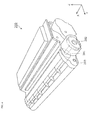
- FIG. 4 is a perspective view of the cartridge 200 according to one or more embodiments of the first example of the present invention.
- the cartridge 200 may comprise the photoreceptor roller 201, the second gear 202, and the engaging portion 203.
- the photoreceptor roller 201 extends in the X-axis direction and is rotatably held around the X-axis.
- the cartridge 200 is mounted on a position where the photoreceptor roller 201 faced the transfer roller 107 of the printer 100.
- the photoreceptor roller 201 may be referred to as a photoreceptor, a photoreceptor drum, or a photoreceptor unit.
- an electrostatic latent image is formed on the surface of the photoreceptor roller 201.
- the electrostatic latent image is made visible by a developing roller (not illustrated) included in the cartridge 200 adhering a developing powder to the electrostatic latent image formed on the photoreceptor roller 201.
- a visual image is formed on the surface of the photoreceptor roller 201.
- the visible image formed on the surface of the photoreceptor roller 201 is transferred to the recording medium that passes between the photoreceptor roller 201 and the transfer roller 107 in the Y-axis direction.
- the second gear 202 is connected to the photoreceptor roller 201.
- the second gear 202 receives power for rotating the photoreceptor 201 from the gear 108 of the printer 100. In other words, the second gear 202 engages the first gear 108.
- the engaging portion 203 protrudes downwards on the tip end portion of the cartridge 200.
- the engaging portion 203 is disposed further downstream in the transporting direction in the cartridge 200 than the photoreceptor roller 201.
- the engaging portion 203 is disposed further downstream in the transporting direction than the photoreceptor roller 201 in the direction where the cartridge 200 proceeds (the direction that the cartridge 200 is inserted) (the positive side of the Y-axis direction) when the cartridge 200 is mounted to the printer 100.
- the engaging portion 203 contacts the protruding portion 109 of the printer 100 while the cartridge 200 for mounting to the printer 100 proceeds.
- the first gear 108 and the second gear 202 are restricted in a direction intersecting the mounting face 106 (Z-axis direction) when the cartridge 200 proceeds until a position where the first gear 108 and the second gear 202 engage.
- the engaging portion 203 engages with the protruding portion 109 (here, the second protruding portion 109b) of the printer 100 in a direction (Y-axis direction) crossing the axis direction of the transfer roller 107 on the mounting face 106 with the cartridge 200 mounted to the printer 100.
- the engaging portion 203 limits the cartridge 200 moving to the upstream side of the transporting direction after the cartridge 200 is mounted to the printer 100.
- FIG. 5 is a cross-sectional view illustrating the cartridge 200 mounted to the printer 100 according to embodiments of the first example of the present invention.
- the first gear 108 of the printer 100 engages the second gear 202 of the cartridge 200 with the cartridge 200 mounted to the printer 100.
- the first gear 108 is disposed further upstream in the transporting direction than the second gear 202.
- the first gear 108 engages with the second gear 202 in the upper side of the first gear 108 and in the downstream side in the transporting direction.
- the second gear 202 passes the upper portion of the first gear 108 when the cartridge 200 is mounted to the printer 100.
- the engaging portion 203 of the cartridge 200 engages with the second protruding portion 109b of the printer 100.
- the movement of the engaging portion 203 to the upstream side in the transporting direction is limited by being caught on the second protruding portion 109b from the downstream side of the second protruding portion 109b.
- FIGS. 6A to 6C are perspective views illustrating the mounting process of the cartridge 200 in the printer 100 according to one or more embodiments of the first example of the present invention.
- the cartridge 200 is mounted to the printer 100 proceeding in the Y-axis direction.
- FIGS. 6A to 6C members of one portion of the cartridge 200 have been removed.
- FIGS. 6A to 6C only members around the vicinity of the second gear 202 are shown in FIGS. 6A to 6C .
- hatching is added to the cartridge 200.
- the second gear 202 of the cartridge 200 is located more to the upstream side in the transporting direction (negative side of the Y-axis direction) than the first gear 108 of the printer 100. Moreover, the protruding portion 109 of the printer 100 does not contact the cartridge 200.
- the engaging portion 203 of the cartridge 200 contacts the protruding portion 109 of the printer 100.
- the first gear 108 of the printer 100 and the second gear 202 of the cartridge 200 are separated by a certain distance.
- the second gear 202 is separated from the first gear 108 in the Z-axis direction. Therefore contact between the first gear 108 and the second gear 202 is avoided.
- the engaging portion 203 moves in the Y-axis direction while contacting the protruding portion 109 (first protruding portion 109a and second protruding portion 109b) in the Z-axis direction when the second gear 202 of the cartridge 200 passes the upper part of the first gear 108 of the printer 100. That is, the engaging portion 203 moves to the positive side of the Y-axis direction while supporting a position higher (the positive side of the X-axis direction) than the mounting face 106. As a result, the second gear 202 surpasses the first gear 108 to the positive side of the Y-axis direction while supporting a position higher (the positive side of the X-axis direction) than the first gear 108.
- the engaging portion 203 of the cartridge 200 contacts the mounting face 106 of the printer 100. That is to say, the cartridge 200 moves lower (the negative side of the Z-axis direction) than the state in FIG. 6B . As a result, the second gear 202 of the cartridge 200 also moves downward (the negative side of the Z-axis direction) and engages the first gear 108.
- the engaging portion 203 engages with the protruding portion 109 (here, the second protruding portion 109b) of the printer 100 in the Y-axis direction. As a result, the movement toward the upstream side in the transporting direction of the cartridge 200 is limited.
- the distance between the first gear 108 and the second gear 202 while the cartridge 200 is proceeding is restricted by the protruding portion 109 protruding from the mounting face 106. That is to say, the first gear 108 and the second gear 202 are separated in a direction crossing the mounting face 106 so that the first gear 108 and the second gear 202 do not contact while the cartridge 200 is proceeding. Therefore, the detaching of the cartridge 200 to the printer 100 can appropriately be assisted and lowering the flexibility in design of the printer 100 can be suppressed even if there is no mechanism provided on the inner side face of the printer 100 for preventing the contact of the first gear 108 and the second gear 202.
- the protruding portion 109 can be provided between the transfer roller 107 and the first gear 108 in the axis direction of the transfer roller 107. Therefore, the protruding portion 109 can be disposed in a region where a bearing of the transfer roller 107 is disposed, or a region where arranged in a direction that crosses the axis direction of that region and the transfer roller 107. As a result, the dimensions of the printer 100 in the axis direction of the transfer roller 107 can be reduced, thereby contributing to the size reduction of the printer.
- the protruding portion 109 can rotatably hold the transfer roller 107. That is to say, that a bearing of the transfer roller 107 can be used as the protruding portion 109 for restricting the distance between the first gear 108 and the second gear 202. Therefore, the length of the second protruding portion 109b in a direction crossing the axis direction of the transfer roller 107 can be reduced on the mounting face 106, thereby contributing to the size reduction of the printer 100.
- the protruding portion 109 of the printer 100 and the engaging portion 203 of the cartridge 200 can be engaged in a direction crossing the axis direction of the transfer roller 107 on the mounting face 106. Therefore, the protruding portion 109 for restricting the distance between the first gear 108 and the second gear 202 when the cartridge 200 is being mounted can be used as a mechanism for restricting the movement of the cartridge 200 after the cartridge 200 has been mounted.
- Embodiments of the second example of the present invention will be described in detail with reference to the drawings.
- Embodiments of the second example differ from embodiments of the first example in the fact that the first protruding portion of the printer has elasticity in a direction crossing the mounting face (the face that transports the recording medium).
- the printer according to embodiments of the second example will be described below focusing on the differences with the embodiments of the first example.
- FIG. 7 is a diagram illustrating a first protruding portion 110 and an elastic member 111 of the printer according to one or more embodiments of the second example of the present invention.
- the first protruding portion 110 rotatably holds the transfer roller 107 around the X-axis.
- the first protruding portion 110 has elasticity in a direction crossing the mounting face 106 (Z-axis direction).
- the first protruding portion 110 has elasticity in the Z-axis direction by the elastic member 111. Therefore, the first protruding portion 110 moves downward when pressure is applied from above and returns to the original position when the pressure from above is removed.
- the elastic member 111 is disposed below the first protruding portion 110.
- the elastic member 111 is a compression coil spring.
- the end face of the compression coil spring contacts the bottom face of a recessed portion 110a formed on the bottom portion of the first protruding portion 110.
- the first protruding portion 110 can have elasticity in a direction crossing the mounting face 106. Therefore, shock can be alleviated when the cartridge 200 contacts the protruding portion 110, and the occurrence of damage to the printer 100 and the cartridge 200 can be reduced.
- the printer was a laser printer, but the present invention is not limited to this.
- the printer may be an LED printer.
- the protruding portion included a first protruding portion and a second protruding portion, but the present invention is not limited to this.
- the protruding portion may include only one of the first protruding portion and the second protruding portion.
- the position of the protruding portion according to one or more embodiments of the present invention is one example, and the position of the protruding portion is not limited to the embodiments described above.
- the protruding portion was provided between the transfer roller and the first gear in the axis direction of the transfer roller, but may also be provided more to the outer side than the first gear.
- the first gear may be provided between the transfer roller and the protruding portion.
- the protruding portion engages with the engaging portion of the cartridge, but it is not absolutely necessary to be configured in this manner.
- the protruding portion may only restrict the distance between the first gear 108 and the second 202 during the progression of the cartridge.
- the elastic member is a compression coil spring, but the present invention is not limited to this.
- the elastic member 111 may be, for example, a plate spring. Furthermore, the elastic member 111 may not be a spring. For example, the elastic member 111 may be rubber.
- the elastic member is separate from the first protruding portion, but may be formed integrally with the first protruding portion.
- the bottom portion of the first protruding portion may be formed in a plate spring shape.
- the engaging portion of the printer 100 (first engaging portion) and the engaging portion of the cartridge 200 (second engaging portion) engage when the cartridge 200 is mounted to the printer 100.
- At least one of the engaging portions of the printer 100 (first engaging portion) and the engaging portion of the cartridge 200 (second engaging portion) may have a shape that protrudes in a direction crossing a face that transports a recording medium. The shape that protrudes may cause the first gear 108 and the second gear 202 to be separated by a distance in the direction crossing the face that transports the recording medium until the first engaging portion engages with the second engaging portion after the cartridge 200 is inserted into the printer 100, and may contact the other of the first engaging portion and the second engaging portion.
Landscapes
- Physics & Mathematics (AREA)
- General Physics & Mathematics (AREA)
- Engineering & Computer Science (AREA)
- Computer Vision & Pattern Recognition (AREA)
- Electrophotography Configuration And Component (AREA)
Applications Claiming Priority (1)
| Application Number | Priority Date | Filing Date | Title |
|---|---|---|---|
| JP2014154190A JP2016031475A (ja) | 2014-07-29 | 2014-07-29 | プリンタ |
Publications (1)
| Publication Number | Publication Date |
|---|---|
| EP2980657A1 true EP2980657A1 (de) | 2016-02-03 |
Family
ID=54007490
Family Applications (1)
| Application Number | Title | Priority Date | Filing Date |
|---|---|---|---|
| EP15178775.1A Withdrawn EP2980657A1 (de) | 2014-07-29 | 2015-07-29 | Kartusche, bilderzeugende vorrichtung und verfahren zur montage der kartusche auf einer bilderzeugenden vorrichtung |
Country Status (4)
| Country | Link |
|---|---|
| US (1) | US20160033933A1 (de) |
| EP (1) | EP2980657A1 (de) |
| JP (1) | JP2016031475A (de) |
| CN (1) | CN105319905A (de) |
Citations (3)
| Publication number | Priority date | Publication date | Assignee | Title |
|---|---|---|---|---|
| EP0496400A2 (de) * | 1991-01-25 | 1992-07-29 | Canon Kabushiki Kaisha | Elektrophotographisches Bilderzeugungsgerät mit einer Montieranordnung für die Arbeitseinheit |
| JPH06317960A (ja) | 1993-04-28 | 1994-11-15 | Canon Inc | 画像形成装置 |
| EP0758105A1 (de) * | 1995-07-31 | 1997-02-12 | Canon Kabushiki Kaisha | Entwicklungsgeräterahmen, Prozesskassette und elektrophotographisches Bilderzeugungsgerät |
Family Cites Families (3)
| Publication number | Priority date | Publication date | Assignee | Title |
|---|---|---|---|---|
| JPH06317953A (ja) * | 1993-04-28 | 1994-11-15 | Canon Inc | フレーム構造及び画像形成装置 |
| JP4671094B2 (ja) * | 2004-05-31 | 2011-04-13 | ブラザー工業株式会社 | 画像形成装置 |
| JP5103821B2 (ja) * | 2006-08-11 | 2012-12-19 | ブラザー工業株式会社 | 画像形成装置 |
-
2014
- 2014-07-29 JP JP2014154190A patent/JP2016031475A/ja active Pending
-
2015
- 2015-07-28 US US14/811,391 patent/US20160033933A1/en not_active Abandoned
- 2015-07-29 CN CN201510455329.1A patent/CN105319905A/zh active Pending
- 2015-07-29 EP EP15178775.1A patent/EP2980657A1/de not_active Withdrawn
Patent Citations (3)
| Publication number | Priority date | Publication date | Assignee | Title |
|---|---|---|---|---|
| EP0496400A2 (de) * | 1991-01-25 | 1992-07-29 | Canon Kabushiki Kaisha | Elektrophotographisches Bilderzeugungsgerät mit einer Montieranordnung für die Arbeitseinheit |
| JPH06317960A (ja) | 1993-04-28 | 1994-11-15 | Canon Inc | 画像形成装置 |
| EP0758105A1 (de) * | 1995-07-31 | 1997-02-12 | Canon Kabushiki Kaisha | Entwicklungsgeräterahmen, Prozesskassette und elektrophotographisches Bilderzeugungsgerät |
Also Published As
| Publication number | Publication date |
|---|---|
| US20160033933A1 (en) | 2016-02-04 |
| JP2016031475A (ja) | 2016-03-07 |
| CN105319905A (zh) | 2016-02-10 |
Similar Documents
| Publication | Publication Date | Title |
|---|---|---|
| JP6202911B2 (ja) | 画像形成装置、プロセスカートリッジ | |
| CN103092048B (zh) | 彩色电子照相图像形成装置 | |
| KR101408430B1 (ko) | 전자사진 화상 형성 장치 | |
| US10488815B2 (en) | Image forming apparatus | |
| JP6984335B2 (ja) | 紙粉回収部材およびそれを備えた画像形成装置 | |
| US9946186B2 (en) | Image forming apparatus including unit attachable to and detachable from apparatus main body, conductive member disposed in unit, contact spring disposed in apparatus main body and configured to come in electrically conductive contact with conductive member, and hollow cylinder disposed in apparatus main body and retaining contact spring | |
| US8725057B2 (en) | Image formation apparatus | |
| EP2738616A2 (de) | Bilderzeugungsvorrichtung | |
| JP6591008B2 (ja) | 画像形成装置 | |
| EP2840448A1 (de) | Bilderzeugungsvorrichtung und Entwicklungseinheit | |
| JP2000181325A (ja) | 電子写真画像形成装置及びプロセスカートリッジ | |
| EP2980657A1 (de) | Kartusche, bilderzeugende vorrichtung und verfahren zur montage der kartusche auf einer bilderzeugenden vorrichtung | |
| US9389535B2 (en) | Image forming apparatus with developing device having ribs | |
| JP6387706B2 (ja) | 画像形成装置 | |
| JP7420979B2 (ja) | プロセスカートリッジ及び画像形成装置 | |
| JP4652384B2 (ja) | 画像形成装置 | |
| US20210063954A1 (en) | Image forming apparatus | |
| CN107145047A (zh) | 带电装置、具备该带电装置的像载体单元和图像形成装置 | |
| JP6460007B2 (ja) | 着脱式ユニット及びそれを備えた画像形成装置 | |
| US20260118798A1 (en) | Image forming apparatus | |
| JP2012013874A (ja) | 画像形成装置 | |
| JP4834572B2 (ja) | 画像形成装置 | |
| CN116841149A (zh) | 图像形成装置 | |
| JP2025097349A (ja) | 画像形成装置 | |
| JP6365462B2 (ja) | 画像形成装置 |
Legal Events
| Date | Code | Title | Description |
|---|---|---|---|
| PUAI | Public reference made under article 153(3) epc to a published international application that has entered the european phase |
Free format text: ORIGINAL CODE: 0009012 |
|
| AK | Designated contracting states |
Kind code of ref document: A1 Designated state(s): AL AT BE BG CH CY CZ DE DK EE ES FI FR GB GR HR HU IE IS IT LI LT LU LV MC MK MT NL NO PL PT RO RS SE SI SK SM TR |
|
| AX | Request for extension of the european patent |
Extension state: BA ME |
|
| STAA | Information on the status of an ep patent application or granted ep patent |
Free format text: STATUS: THE APPLICATION IS DEEMED TO BE WITHDRAWN |
|
| 18D | Application deemed to be withdrawn |
Effective date: 20160804 |