EP2980761A1 - Unite de terminal destinee a la verification d'un document de securite - Google Patents
Unite de terminal destinee a la verification d'un document de securite Download PDFInfo
- Publication number
- EP2980761A1 EP2980761A1 EP15178038.4A EP15178038A EP2980761A1 EP 2980761 A1 EP2980761 A1 EP 2980761A1 EP 15178038 A EP15178038 A EP 15178038A EP 2980761 A1 EP2980761 A1 EP 2980761A1
- Authority
- EP
- European Patent Office
- Prior art keywords
- document
- security document
- security
- sensor
- terminal unit
- Prior art date
- Legal status (The legal status is an assumption and is not a legal conclusion. Google has not performed a legal analysis and makes no representation as to the accuracy of the status listed.)
- Granted
Links
Images


Classifications
-
- G—PHYSICS
- G07—CHECKING-DEVICES
- G07D—HANDLING OF COINS OR VALUABLE PAPERS, e.g. TESTING, SORTING BY DENOMINATIONS, COUNTING, DISPENSING, CHANGING OR DEPOSITING
- G07D7/00—Testing specially adapted to determine the identity or genuineness of valuable papers or for segregating those which are unacceptable, e.g. banknotes that are alien to a currency
- G07D7/01—Testing electronic circuits therein
-
- G—PHYSICS
- G07—CHECKING-DEVICES
- G07D—HANDLING OF COINS OR VALUABLE PAPERS, e.g. TESTING, SORTING BY DENOMINATIONS, COUNTING, DISPENSING, CHANGING OR DEPOSITING
- G07D7/00—Testing specially adapted to determine the identity or genuineness of valuable papers or for segregating those which are unacceptable, e.g. banknotes that are alien to a currency
- G07D7/17—Apparatus characterised by positioning means or by means responsive to positioning
Definitions
- the invention relates to a terminal unit for the automatic verification of a security document and to a corresponding method.
- the ICAO International Civil Aviation Organization
- the ICAO International Civil Aviation Organization
- the ICAO International Civil Aviation Organization
- the ICAO International Civil Aviation Organization
- the ICAO defines i.a. the formats for machine-readable travel documents.
- the document describes passports with machine readable data in text recognition format and specifications for electronic passports with biometric identification capabilities using embedded RFID chips.
- security documents in the format ID-1 (ISO / IEC 7810, equivalent to 85.60 mm x 53.98 mm) are used.
- Application areas are z.
- the old German identity card had the format ID-2 (105 x 74 mm).
- Visa labels often have the ID-2 format so they can be pasted into passports.
- the German passport itself has the format ID-3 (125 x 88 mm).
- the ID-3 format determines the size of passports worldwide. Passports with a flexible envelope (eg the provisional German passport) usually correspond exactly to the ID-3 format, in the case of passports with a fixed envelope (eg the German ePass) the insides are in the ID-3 format, while the Cover protrudes approx. 2 mm.
- a flexible envelope eg the provisional German passport
- a fixed envelope eg the German ePass
- terminals are used to automatically verify the security documents and thereby check whether a person is really the person for whom he or she claims to be using the security document and / or to check whether the security document is genuine and valid.
- the publication DE102004056007 A1 (Mobile verification device for checking the authenticity of travel documents) describes a mobile verification device for authenticity verification of travel documents, which weighs less than 1000 g, especially less than 700 g.
- the verification device comprises an identification device for identifying an authorized user, a release device, an optical reading unit for reading on the pages the pictorial and / or alphanumeric information contained in the travel document, a data processing unit for processing the signals supplied by the optical reading unit, and a display unit for displaying the read-out data and the determined verification result.
- document DE 102013206700 A1 (Device and method for document detection) describes a device for document detection, wherein the device has at least one support surface for supporting a document, wherein the device has at least one cover member for covering the support surface, and a corresponding method for document detection.
- DE 202007000708 U1 (Device for reading identification documents) describes a device for reading identification documents, in particular of electronic identity documents, comprising a reading unit, which can be brought into a read-out position with respect to a passport document and makes it possible to carry out an authenticity check and / or a function test of the passport document.
- DE10028241 A1 (Document verification device) describes a document testing device for the automatic testing of value and security documents, which has a movable in the XY direction cross slide, on which the necessary components for the evaluation of the authenticity features are arranged.
- the X slide of the cross slide which can be moved in the X direction, is movably arranged within an outer Y slide which can be moved in the Y direction, wherein a first group of evaluation units for evaluating the diffraction structure on the X slide with laser and evaluation optics and a second group of evaluation components, for example, for evaluating a text, IR field and / or a photo field, is arranged on the Y-carriage.
- DE10 2012003241 A1 (Device and method for the automatic verification of value and / or security documents) describes a device for automatic testing of value and / or security documents with a support surface for the value and / or security document and a first test device and at least one second test device.
- the particularly compact, inexpensive and equipped with a robust mechanism device is characterized in that it comprises a holding element to which a first arm and at least one further arm is at least temporarily fixed rigidly, wherein the first test device on and / or in the first arm and the at least one second test device is arranged on and / or in each case a further arm.
- the invention is the object of the invention to provide an improved terminal unit and method for verification of a security document.
- a "security document” is a document that includes one or more security features that are intended to make it difficult or impossible to duplicate and / or falsify information from a simple copy and that are stored in the security document or physically applied or imprinted.
- the information stored in the security document may include, for example, a name, date of birth, place of birth, place of residence, nationality, height, eye color, skin color, gender, graphic representation of the security document associated person, in particular a passport photo, biometric data of the person associated with the identity document, such as fingerprint data, iris information, facial information, etc.
- a security document may also include information that identifies the security document itself, such as a badge number, and characteristic security features. In the following, the security document is also referred to as "document" for short.
- a security document may e.g. a banknote, a check, a ticket, or an identity document.
- the identity document may be, for example, a passport, an identity card, an identity card, a driver's license, a work permit, and so forth.
- a terminal is a user terminal for entering and displaying data.
- a terminal includes a contactless or contact interface for exchanging data with a security document.
- a terminal may be located within or at the entrance of a security facility, e.g. at airports, railway stations or the entrance of a company premises.
- excitation source is a component or functional unit of a device from which an excitation signal, e.g. a light signal is emitted or can be emitted. Excitation sources can be divided into different types according to the nature of the signal you generate (light of different wavelength ranges, ultrasound, etc.).
- a “sensor” is a component or functional unit of a component that is capable of sensing signals that are scattered, reflected, or reflected by a security element when excited by an excitation source.
- the sensed signal thus depends both on the nature of the security element from which it is received and on the nature (wavelength, intensity) of the excitation source.
- a “security element” is a spatial or structural unit that comprises or represents at least one security feature.
- security features Such features are referred to, which make it difficult and / or impossible to imitate, falsify and / or copy the security document.
- visible light is understood as meaning light having a wavelength in the range from 381 to 780 nm.
- Red light is understood to mean light having a wavelength of 641 to 780 nm.
- Orange light is understood as meaning light having a wavelength of 601 to 640 nm.
- Yellow light is understood as meaning light having a wavelength of 571 to 600 nm.
- green light is meant light having a wavelength of 490 to 570 nm.
- blue light is meant light having a wavelength of 430 to 490 nm.
- Violet light is understood to mean light having a wavelength of 380 to 430 nm.
- Ultra-violet light (UV) is understood as meaning light having a wavelength of 200 to 380 nm.
- UV-A with a wavelength of 316 to 380 nm
- UV-B with a wavelength of 281 to 315 nm
- UV-C with a wavelength of 200 to 280 nm.
- a wavelength of 375 nm is preferred, in the UV-B range of 312 nm and in the UV-C range of 253 nm.
- IR infrared light
- NIR near infrared light
- NIR having a wavelength of 781 to 1100 nm is used.
- the invention relates to a terminal unit for machine verification of a security document.
- a "terminal unit” is a component or module that can be installed in a terminal.
- the terminal unit includes a feed opening and catching means for automatically feeding the security document in the opened state into the intake opening.
- the collection means are adapted to retract the unfolded security document so that in this case the wide edge of the lid or the wide edge of the rear wall of the security document is pulled in towards the feed opening.
- the terminal unit comprises an RFID card reader which is adapted to receive data from an RFID chip of the recovered security document read, provided that the RFID card reader and the RFID chip are each at a reading position inside the terminal unit.
- the terminal unit comprises a type recognition module for automatically detecting a document type of the security document and for automatically determining a document type-specific position of the RFID chip within the deployed security document based on the recognized document type.
- the RFID chip may be inside or on the lid, inside or on the back wall, or inside or on an inside of the security document.
- the terminal unit comprises a drive which is designed to automatically move relative to one another based on the determined position of the RFID chip, the RFID card reader and the retracted folded security document so that both the RFID card reader and the RFID chip in their respective Reading position are located.
- the terminal unit also comprises a verification module, which is designed to read out data from the RFID chip of the security document by means of the RFID card reader after the movement of the RFID card reader and the security document to reach the respective read positions and to verify the security document based on the read-out data.
- the verification result may be displayed, for example, via a graphical display device of the terminal or the terminal unit.
- such a terminal unit may be advantageous, since the described collection mechanism could enable a fully automated, fast, user-friendly and less error-prone document review: by allowing the document to be automatically retracted, it would be possible to prevent an untrained user, who rarely, for example in the course of a holiday trip at the airport, identifies himself at a terminal, interrupts the document check by prematurely withdrawing the document from the terminal.
- the user or operator need not pay attention to whether the document is placed up or down in the insertion opening, for example to ensure that the RFID chip comes to rest in the right place above the RFID card reader. Rather, the format and type of security document are automatically detected and the RFID card reader and security document positioned accordingly. This could also reduce the time required for document validation, since time lost due to misplacing the security document (coupled with the automatic ejection of the document and one or more attempts by the user to properly insert the document) can be avoided.
- the fact that documents can also be retracted and automatically checked in the unfolded state can be advantageous since the height of the terminal unit can be reduced. A more compact design could be realized thereby. This can be particularly advantageous if the terminal unit is intended for installation in a mobile terminal.
- the described terminal unit may be advantageous, since duplicate retraction and scanning of large format security documents such as the passport in the ID-3 format may become unnecessary: depending on the country and type of passport, the passport may include an RFID chip in its lid, within its back wall or in or on a data page.
- the terminal unit described above has the advantage that an RFID chip, regardless of whether it is in the lid or in the back wall of the security document, is pulled into the interior of the terminal unit and there, if necessary can be tested. A double collection, evaluation and output of the security document and the associated loss of time can thus be avoided.
- a security document in the "unfolded state” is understood to mean a security document which has at least one cover and one security document Rear wall and optionally also includes one or more inner sheets, which are connected to a document back with each other.
- the lid and the rear wall have at the spine on a Tarklappwinkel of approximately 180 °.
- the flip-up angle can be between 170 and 190 °, for example.
- the document output can be carried out after the RFID chip has been read so that the document is transported back to the feed opening by the feed means (which, for example, rotate in the opposite direction to the document feeder during output).
- the security document is stopped at a position where the catch means, eg pick rollers, still grasp and hold the document so that it does not fall, and can be easily picked up by the user.
- the collection means are dimensioned and positioned so that security documents in smaller formats, for example check card formats, ID-2 and ID-1 formats, can be safely drawn in and issued without the small-format security documents tilting and being skewed.
- the terminal unit further comprises a feed surface, which allows the security document to be placed on the feed surface in the unfolded state.
- the collection means are designed to automatically retract an opened and placed on the catchment surface security document.
- the feed surface is preferably large enough for a document to be placed in the ID-3 format without falling down.
- the feed surface may be inclined towards the intake opening so that an applied security document automatically slips so far into the intake opening that it can be automatically picked up and pulled in there by the intake means.
- the feed surface may for example be 100 mm x 160 mm or even larger.
- the insertion opening has guide elements, for example a funnel-shaped attachment, which allows manual insertion of the security document into the intake opening to a point where the security document automatically fed, facilitate.
- a feed surface may also be present in these embodiments.
- the feed surface and / or the guide elements can thus facilitate the insertion of the security document into the feed opening and thus speed up the document verification process.
- the operator at the terminal can thus use the hands for other tasks, such as entering a PIN or the capture of at least one fingerprint.
- the RFID card reader is immobile and the drive is designed only to move the security document.
- the movement of the security document may e.g. take place only along the feed direction or in addition to it at a 90 ° angle to the feed direction within the plane, which is spanned by the recovered security document.
- the drive is designed to move the RFID card reader and the security document.
- the automatic retraction of the document and all steps required for its verification and executed by the terminal unit are automatically initiated by a user inserting the security document more than a predefined minimum depth into the intake opening.
- the RFID card reader has an antenna with an area of at least 70% of the feed surface.
- Such a large antenna can be advantageous since it makes the probability that the RFID chip of the document is already at a suitable reading position after the security document is completely inserted that is detected by the antenna of the RFID card reader very high. This can also increase the probability that the document or the RFID card reader need not be moved at all, so that data can be read from the RFID chip of the security document. This can speed up the process and reduce wear on the moving parts of the drive.
- the terminal unit includes an electronic database in which a plurality of security document types are stored.
- each of the security document types is assigned one or more security elements as well as security-element-specific data.
- the security element specific data may e.g. Reference values of signals from security elements that were irradiated with light of a certain wavelength.
- these data may include the location of the security element within the security document, that is, information on which page and at which position within that page a security element is located. Further, these data may include instructions on how to test the security element.
- the terminal unit may have a network interface for connection to a corresponding database via a network, e.g. the internet, own. The data transmission can e.g. via SOAP / XML messages.
- the terminal unit may include an upper module having a first excitation source and a first sensor.
- the terminal unit may comprise a lower module with a second excitation source and a second sensor.
- the upper module is positioned above the intake opening, the lower module is positioned below the intake opening.
- the first and second excitation sources correspond to a first excitation type and are designed to excite at least a first security element of the recovered security document during the collection of the security document.
- the first and second sensors are designed to receive a first signal during the collection of the security document, if it emanates from the at least one excited first security element in the direction of the respective sensor.
- the first signal corresponds to a first type of signals that can be received by the first and second sensors.
- the verification module When verifying the security document, the verification module not only evaluates the data read, but also evaluates and considers the first signal and other data associated with the at least one first security element. For example, it may be considered whether a first signal has ever been received, and if so, whether the signal has been received by the first or the second sensor. If e.g. if the excitation starts from the first excitation source and the first security element lies on the upper side of the document, the first signal will be received by the first sensor, since both are in the upper module. If e.g. if the excitation originates from the second excitation source and the first security element lies on the lower side of the document, the first signal will be received by the second sensor, since both are located in the lower module.
- the further information for the document type of the recovered document may contain, for example, whether the first security element is contained on the lid, the back wall or a data page of the security document, as well as the position inside the lid, back wall or data page.
- the received first signal may be evaluated to check where the first signal would have been expected given the type of document presently present and if it was also detected there and corresponds to an expected value, eg a reference value specifically stored for the first security element.
- the further data verified during verification may include, for example: the time when an excitation source was active, the excitation type of the excitation source (eg UV light, IR light, white light, etc.) and whether the position of the excitation source (eg either in the upper module or in the lower module); The time when a sensor sensed a corresponding signal, the position of the sensor (eg either in the upper or lower module), sensitivity range of the sensor, etc.
- This may include the examination, based on an image analysis of a scan of the top and bottom of the unfolded document determine whether the cover of the document is at the top or bottom, and whether, taking into account this identified situation of the security document, the first signal was received there, where it was expected and must be received, if the document is genuine.
- the database may contain over 1000 document types from different countries, each of which may have different functions. For each stored document type its format, the position of its RFID chip as well as position, type and possibly reference data of the security elements contained in the document type can be stored in the database.
- the excitation and examination of the at least one first security feature at the same time as collecting the security document may be advantageous since it can reduce the overall time for verification of the security document.
- the terminal unit further comprises output means for outputting the security document after carrying out the readout of the data from the RFID chip of the security document.
- it includes a third excitation source and a third sensor, which are each part of the upper module, and a fourth excitation source and a fourth sensor, which are each part of the lower module.
- the third and fourth excitation sources are of a second excitation type and the third and fourth sensors are configured to sense a second type of signal.
- wheels and rollers which are movable in both directions, serve both as catchment means and as output means.
- the third and fourth excitation sources are designed to stimulate at least a second security element of the security document during the output of the security document.
- the third and fourth sensors are designed to receive a second signal during the output of the security document, if it emanates from the at least one second security element excited by the third or fourth excitation source in the direction of the third or fourth sensor. For example, if the excitation originates from the third excitation source and the second security element lies on the upper side of the document, the second signal will be received by the third sensor, since both are in the upper Module are located. For example, if the excitation originates from the fourth excitation source and the second security element is on the lower side of the document, the second signal will be received by the fourth sensor, since both are in the lower module.
- the second signal is of a second signal type. In the verification of the security document in addition to the data read in addition to the second signal and other data associated with the at least one second security element, evaluated and taken into account by the verification module.
- the further data associated with the at least one first security element comprises an indication of the position of the at least one first security element.
- the verification of the security document includes a check as to whether the position of the at least one first security element contained in the associated further data matches a position communicated by means of the first signal.
- the position communicated by the first signal also includes whether the first signal was received from the first sensor or the second sensor.
- by automatically e.g. Based on a scan, it is determined whether the top or the bottom of the unfolded document, for example, facing the upper module, it can be determined whether the first security element is where it should be in the current document type.
- the further data associated with the at least one second security element may include an indication of the position of the at least one second security element.
- the verification of the security document may include a check as to whether or not the associated further data contained position of the at least one second security element with a position communicated by means of the second signal position, wherein the position communicated by means of the second signal also includes whether the second signal was received from the third sensor or the fourth sensor. Accordingly, it is also possible to proceed with further, eg third, fourth and fifth security features, and the terminal unit can correspondingly have further pairs of excitation sources and matching sensors in each case above and below the document feeder.
- the first and second excitation sources each comprise at least one source of electromagnetic radiation in a first wavelength range.
- the first and second sensor is in each case a sensor for a first further wavelength range of electromagnetic radiation, the first further wavelength range being a wavelength range in which the at least one first security element emits the first signal after excitation by the first or second excitation source.
- the first wavelength range and the first further wavelength range may be identical, for example if the security element only deflects and / or partially absorbs the incident light beam. However, they need not be identical, for example if the security element contains a fluorescent substance, so that it emits light ("signals") in another spectral range than in the region in which it was excited or irradiated.
- the third and fourth excitation sources are each a source of electromagnetic radiation in a second wavelength range.
- the third and fourth sensor is in each case a sensor for a second further wavelength range of electromagnetic radiation, wherein the second further wavelength range is a wavelength range in which the at least one second security element emits the second signal after excitation by the third or fourth excitation source.
- the second wavelength range and the second additional wavelength range may be identical, but need not.
- both the first and second excitation sources emit electromagnetic radiation in the first wavelength range during document feeding.
- Both the third and fourth excitation sources emit electromagnetic radiation in the second wavelength range during document output.
- the first wavelength range is a range of 781 nm-1100 nm and the second wavelength range is a range of 381 nm-780 nm or vice versa.
- the first wavelength range is a range of 381 nm-780 nm and the second wavelength range is a range of 315-380 nm.
- the first wavelength range is a range of 315 nm - 380 nm and the second wavelength range is a range of 781 nm - 1,100 nm or vice versa.
- the terminal unit further comprises a fifth excitation source and a fifth sensor, both of which are part of the upper module. It also comprises a sixth excitation source and a sixth sensor which is part of the lower module.
- the fifth and sixth excitation sources are of a third excitation type, ie, are designed to emit an excitation signal of a specific type, for example an electromagnetic radiation of a specific wavelength.
- the fifth and sixth sensors are adapted to sense a third type of signal.
- the fifth and sixth excitation sources are designed to encourage at least a third security element of the security document during the collection of the security document.
- the fifth and sixth sensors are designed to receive a third signal during the collection of the security document, if this third signal emanates from the at least one excited third security element in the direction of the fifth or sixth sensor.
- the verification module is additionally designed to evaluate and to take into account the third signal as well as further data associated with the at least one third security element during the verification of the security document.
- the fifth and sixth excitation sources may e.g. each represent a source of electromagnetic radiation in a third wavelength range.
- the fifth and sixth sensors can each represent a sensor of electromagnetic radiation that is specific for a third further wavelength range.
- the third further wavelength range is a wavelength range in which the at least one third security element emits the third signal after excitation by the fifth or sixth excitation source.
- the third wavelength range and the third additional wavelength range may be identical, but need not.
- the first wavelength range used in document feeding for security element testing is a range of 781 nm - 1100 nm, preferably 890 nm. This wavelength range corresponds to infrared light.
- the second wavelength range used in the document output to test other security elements is a range of 380 nm-780 nm ("white light").
- the first wavelength range can also be white light and tested in the document feeder, and the second wavelength range can be in the infrared range and checked during document output.
- the first wavelength range is a range of 381 nm - 780 nm (white light) and the second wavelength range is a range of 200 to 380 nm, preferably 315-380 nm (UV-A light), particularly preferably 365 nm the reverse case (first wavelength range is UV light, second wavelength range is white light) is possible.
- the first wavelength range is a range of 200 to 380 nm, preferably 315-380 nm, particularly preferably 365 nm (UV light) and the second wavelength range is a range of 780 nm-1100 nm, preferably 890 nm (infrared light).
- first wavelength range is UV light
- second wavelength range is infrared light
- the first wavelength range (used in the document feeder) is a range of 381 nm-780 nm
- the second wavelength range (used in the document output) is a range of 315-380 nm
- the third wavelength range (also used in the document feeder) Range of 781 nm - 1,100 nm.
- the terminal unit and its first to sixth sensors or excitation sources can also be designed so that the document feeder is tested only with UV light of wavelength 315-380 nm (ie, that the excitation source emits light of the appropriate wavelength) and at the document output both with IR light of wavelength 781 nm - 1100 nm and with white light of wavelength 381 nm - 780 nm.
- the terminal unit also includes a fifth and sixth excitation source and corresponding sensors, it is preferably during the document feeder both in the upper and in the lower module, the infrared light and white light based excitation sources and the corresponding sensors activated and detected corresponding signals.
- the excitation by the IR light and the white light can take place at the same time or offset in time.
- the UV light-based excitation sources and the corresponding sensors are activated in both the upper and lower module and corresponding signals are recorded. This combination of UV light and IR light or white light has proved to be particularly favorable in order to reduce the mutual influence of radiation sources and sensors of different types ("extraneous light").
- the sensitivity range of the corresponding sensor pair (each in the upper and lower module, a sensor of the same type) with the wavelength range of the infrared light should preferably be the same or similar.
- the sensitivity range of the corresponding sensor pair should preferably be the same or similar to the wavelength range of the white-light range.
- a white light LED may e.g. be generated by combining several LED chips of different colors in a common LED housing. As a result, different of the LED chips are superimposed to white light. It is also possible to cover a blue LED with an internal luminescent layer, which converts part of the blue light into yellow light, so as to produce all the essential spectral components of "white light”.
- red, blue and green partial light sources at the same time instead of a single white light source, wherein the red partial light source (eg LED) in a wavelength range of 640 to 780 nm, the blue partial light source in a wavelength range from 430 to 490 nm and emitted the green partial light source in a wavelength range of 491 to 570 nm.
- a partial sensor is used which has a comparatively narrow range of sensitivity wavelengths, which largely corresponds to the emission spectrum of the red, blue or green partial light source. This can be achieved for example by color filters.
- the signals received by the sub-sensors can be superimposed by a processor, eg a processor of the control unit of the terminal unit, into an overall image whose RGB values largely correspond to the RGB values which would have arisen under a single white-light source.
- the red, green and blue partial light sources emit light sequentially and a single sensor (“gray light sensor”) is used covering the entire spectral range of the white light.
- This sensor not only records the signals emanating from a security element after being excited by one of the RGB partial light sources, but also information that allows an association between the received signal and the partial light source active at that time.
- These data allow the processor of the control unit to compute an overall image of the document or at least the stimulated security element whose respective R, G and B components are composed of the signals produced by the individual partial light sources.
- RGB red
- G green
- B blue
- RGB red
- B blue
- a brightness value for the respective color can be calculated from the brightness values (“gray values") received by the sensor.
- the brightness value of a color may be stored as 8-bit information. Then these three values are put together to a colored RGB image, which can have eg 24 bits per pixel.
- the sensitivity range of the corresponding sensor pair should preferably be the same or similar to the wavelength range of the UV light.
- Sensor type [with regard to sensed wavelength range] document feeder White light White light sensor : (white LED: 381 to 780 nm) a) a general white light sensor for broad light spectrum of about 381 to 780 nm; The sensor detects when a signal was taken and assigns the signal to a blue, red or green excitation source.
- red LED (640 - 780 nm) blue LED: (430 - 490 nm) green LED: (491 - 570 nm)
- RGB sensor one sensor each for the R, G and B flashes (eg three general white light sensors + corresponding color filters); Each type of sensor is designed to receive only the blue, red or green excitation light
- the terminal unit contains a program which calculates an RGB image from the three RGB signals received according to a) or b).
- document feeder infrared light Preferably, a sensor for a broad Lichtspecktrum of about 380 nm - 1,100 nm.
- the senor is a white light sensor to test fluorescent security elements that are excited by UV radiation to emit signals in visible light. (200-380 nm, preferably 315-380 nm, particularly preferably 365 nm)
- the first excitation source (for 381 to 780 nm white light) and the third excitation source (for 781-3000 nm IR light, preferably 781-1100 nm, more preferably 890 nm) are combined in a single package comprising a plurality of LEDs (each for R (red), G (green), B (blue), and IR (infrared).)
- the second excitation source (white light) and the sixth excitation source (for IR light) are also grouped into a single unit LEDs (each for R, G, B and IR)
- the third and fourth excitation source (UV) are each combined in a separate unit
- each of the RGB-IR unit and the UV unit has its own sensor with a 380 nm - 1,100 nm, which can calculate an RGB image and an IR image based on the known emission times of the individual LED diodes, which can then be subjected to an image analysis by the terminal unit In order to determine whether a particular security element causes
- the first, second, third, fourth, fifth and / or sixth excitation source each consist of an indirect illumination device, which comprises an electromagnetic radiation source, e.g. an LED light bar, and a reflective element.
- the reflection element scatters the radiation of the radiation source in such a way that at least parts of the scattered radiation fall on the surface of the security document facing the radiation source and thus also on possibly existing security elements in the vicinity of the excitation source.
- the first, second, third and / or fourth sensor each consist of a scanner, in particular a line scanner.
- a line scanner, also called a line sensor is a radiation-sensitive, in particular light-sensitive detector (usually semiconductor detector), which consists of a one-dimensional array of photodetectors or other detector elements.
- CCD and CMOS line sensors can be used which operate in the range of UV light, visible light and near and medium infrared.
- the excitation source may e.g. consist of one or more LEDs, e.g. from a LED strip.
- a LED strip may extend over almost the entire length of the feed opening.
- the first and second excitation sources and the first and second sensors are arranged to operate simultaneously during the collection of the security document and during the feed a first scan from an upward surface of the security document and a second scan from a downward Generate the surface of the security document.
- a "scan" is understood here as an image file.
- the scan is received by a control unit of the terminal unit.
- the scan is recorded in the visible range, eg white light range, or in the infrared range, ie, the first and second excitation sources and the first and second sensors are preferably either in the white light region emitting or in the infrared region in these embodiments.
- Performing the scan at the same time as the document feeder can be advantageous since, in addition to the retraction movement of the document, no additional movement of device components is required to generate the scan. This can reduce the wear of components.
- the security document has a "machine readable zone" (MRZ).
- MRZ machine readable zone
- the control unit is designed to automatically determine the MRZ from the first or the second scan and to enable authentication of the security document with the aid of the determined MRZ of the terminal unit. Reading out the data from the RFID chip is only possible after successful authentication of the terminal unit against the security document. Such a determination of the MRZ can be advantageous since it protects the security document from the fact that personal data is read from the RFID chip against the will of the user. Since both a scan of the top and bottom sides of the document are determined at the same time, it is not necessary to insert and flip the document twice, nor is it necessary for the user to be careful to place the document in a particular orientation.
- control unit could determine whether the present document should contain an MRZ at all and, if so, where. Both the first and second scans are then subjected to image analysis to determine which of the two scans contains the MRZ and whether it has been recognized at the position where it would have to be in accordance with the identified document type.
- the type recognition module is configured to perform the automatic recognition of the document type of the security document only after complete insertion of the security document up to a stop position, whereby the recognition of the document type is carried out on the basis of the first and / or the second scan. Possibly. It may be necessary for the security document to be moved back a little from the stop position in the direction of the intake opening in order to bring its RFID chip into read position.
- the use of the first and second scans to determine the document type can be advantageous, since both the document type and the MRZ can be determined from the same data base (two scans), ie a multiple use of data can be performed can only have been collected in a single step.
- the catch means are elastically deformable or displaceable in the document feeder, so that security documents which have a thickness of 2 mm-10 mm in total or in the unfolded state (even during the document feed or output) are prevented from slipping and / or bulging can be and are only movable when a minimum force acts on them, for example exercised by the means of collection.
- the elasticity can be achieved, for example, by elastic mounting of the pulling-in means (for example wheels or rollers), e.g. by means of springs or elastic materials such as rubber.
- the collection means may e.g. consist of a plurality of friction wheels and / or a friction belt for transporting the document from a retraction position into the interior of the terminal unit.
- first, second, third, fourth, fifth or sixth sensors are elastically deformable or displaceable during document feeding, so that security documents which have a thickness of 2 mm-10 mm overall or in the unfolded state are thus held by the sensors in that movement of the security document relative to the sensors is possible only by the action of a force exceeding a minimum height.
- the force it may be necessary for the force to be at least as high must be like the force applied to the collection of the security document by the collection means. This can be advantageous since a uniform contact pressure could also be achieved in the area of document back-off, which in turn could increase the overall quality of the scans and / or the verification process.
- the intake opening is formed in a slot shape.
- the terminal unit further comprises a movable positioning means for positioning the security document in front of or in the feed opening.
- the positioning means is designed to exert a displacement force parallel to the edge-shaped intake opening on the security document laid on the egg-handling surface. This displacement force causes the launched security document occupies a retraction position.
- the positioning means and / or the collection means can align the security document during collection so that its wide cover or rear wall edge is arranged parallel to the slot-shaped intake opening. This may be advantageous because document skewing in automatic document feeder could be prevented and the quality of the scans or evaluation of the security elements improved because no distortion effects reduce the scan quality or corrupt the position information in the sensed first and second signals.
- the upper module includes an upper cassette.
- the upper cassette and the upper module are configured so that the upper cassette can be repeatedly taken out and reinserted from the upper module, with a first part of the drawing means and at least the first excitation source and the first sensor being located inside the upper cassette and so configured are that they can be removed and reused as part of the upper cassette.
- the lower module may include a lower cassette, wherein the lower cassette and the lower module are configured so that the lower cassette can be repeatedly removed and reinserted from the lower module.
- a second part of the catchment and at least the second The excitation source and the second sensor are located inside the lower cassette and are designed so that they can be removed and reused as part of the lower cassette.
- the rollers could be driven from outside the upper and lower cassettes, such as by a motor and a plurality of force-transmitting elements that transmit the power of the motor to those parts of the rollers that are external to the cassette (s) and into one Rotate rotary motion of the rollers.
- the collection means e.g. Rollers or cogs can become dirty in continuous operation after some time. It may also be that individual LEDs, which serve as an excitation source, are no longer functional after expiration of the usual service life. In this case, only one cartridge needs to be replaced to load new LEDs and / or clean rolls for the document feeder. Failure of the terminal for several hours or even days until the arrival of a service technician could be avoided.
- the invention relates to a terminal including a user interface and the terminal unit according to one of the aforementioned embodiments, wherein the terminal unit has an interface for data exchange with the user interface.
- the user interface can consist, for example, of a keyboard for inputting a PIN and / or a display device for displaying usage instructions, error messages and / or the result of the verification of the security document.
- the interface for exchanging data between the terminal unit and the user interface may, for example, enable the user to whom the security document is assigned to authenticate to the security document by means of an entered PIN and / or to indicate to the operator of the terminal whether the security document has been successfully verified or not.
- a successful verification means that the check of at least the data read from the RFID chip and possibly additionally the examination of further data and security elements revealed that the security document is not a forgery, is still valid, and, if the security document is an identity document, is associated with the correct person.
- the terminal can be designed in particular as a mobile terminal.
- the terminal can be used, for example, for the following purposes: international border control at airports, seaports and border crossings; automatic border control, self-service by the citizen; Document control by police, customs, embassies and banks and by document manufacturers in the course of quality control.
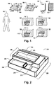
- the FIG. 1 10 shows a security document 108, for example a fold-out electronic passport, associated with a user 102.
- the security document may include a lid 110 and a rear wall 112 and a plurality of inner sides P3, P4, P5, P6.
- Lid and back panel can be made of thicker material, eg reinforced cardboard, be designed as the insides.
- the document may have personal data printed in text form.
- personal data such as name and address or biometric data (fingerprint data, iris scan, facial portraits, etc.) may be stored as reference data in an RFID chip integrated in the lid, the back wall or one of the inner sides or attached to their surfaces ,
- embodiments of the terminal unit 200 shown in FIG Figures 2-7 be shown in more detail, for example, be installed in a small, mobile terminal 116 and allow a very user-friendly and less error-prone automated document verification.
- the four scenarios 120, 122, 124 and 126 illustrate the different ways in which a user may insert the security document into the terminal unit's access port to verify the document.
- the wider edge of the lid 110 of the security document 108 is referred to below as k1
- the wider edge of the back 112 is referred to as k1 '.
- the shorter edge of the lid or back is called k2.
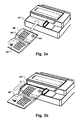
- FIG. 2 shows a terminal unit 200 comprising an upper module 202 and a lower functional module 204.
- the body of the two modules 202 and 204 may form a one-piece component.
- each module can also be a separate, one-piece or composite component.
- the upper module 202 is located above a slit-like intake opening 206, the lower module 204 is below the intake opening and forms the bottom of the terminal unit.
- the gap-shaped intake opening may be formed as a gap, ie, from an approximately rectangular limited opening (see, for example, the in Fig. 4 illustrated intake opening). But it is also possible that the lower and upper unit form an open towards one side, U-shaped limited intake opening 206 (see FIG. 2 and 3 ).
- the terminal unit may optionally include a document support surface 208 on which the document may be stored so as to be automatically captured by the automatic document feeders. This can facilitate the operation of the terminal, as the operator has both hands free for other tasks, such as the input of PINs or the capture of biometric data, such as fingerprint data.
- the terminal unit may include positioning means 210, such as resilient clip retainers, which enclose the document from one or two sides and position the document on the document support surface 208 so that the document does not tilt during the retraction operation.
- Positioning means are preferably adapted to position a plurality of different document sizes and formats so that they can not tilt during the feeding operation and position both unfolded "booklet-style" documents and credit-card sized security documents suitable for automatic feeding.
- the clip holders could move the document flush to a side edge of the feed opening or move to the middle of the intake opening.
- the positioning means themselves are so flexibly adjustable that they can correctly position documents in different formats, eg in ID-1, ID-2 and ID-3 format.
- Within the upper and / or lower module may be a removable and possibly also hinged cassette 216, which in the notes to FIG. 4 is described in detail.
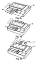
- FIG. 3 shows an image sequence about the entry of a security document 108 by a terminal unit 200 to verify the security document.
- the verification can be carried out in a method according to FIG. 9 done so that FIG. 9 and FIG. 3 will be described together below.
- the security document may include one or more security elements 302, 304, 306 on the insides and / or on the inside or outside of the lid or the back wall of the document 108.
- security element 306 may be a hologram that is visible under white light and, for example, can be compared to a reference image stored in a database during the verification of the security document.
- Security element 302 may be an imprint that is visible only under UV illumination (for example, because the imprint is made of a UV light-reflecting substance or a substance that fluoresces in UV light).
- Security element 304 may be an imprint that is visible only under infrared illumination or is visible, for example, in white light, but not in infrared illumination.
- security elements are described by way of example only, a variety of other types of security elements, based for example on metal-coated foil elements, fluorescence, phosphorescence, reflection or absorption of certain spectral line regions are possible and known in the art.
- FIG. 3a shows that such a security document 108 can be placed, for example with the unfolded inside up on the support surface 208 of the terminal unit 200 so that the broad side k1 'of the rear wall 112 substantially lies parallel to the slot-shaped intake opening.
- the positioning means 210 may help align the laid-up document 108 so that it does not skew during document feeding.
- the document can also be inserted by a user directly into the intake opening.
- FIG. 3b shows a security document aligned by the positioning means 210.
- the feed direction in the terminal unit is shown with a large arrow.
- pulling-in means for example rollers, pull the document into the intake opening in the unfolded state.
- the wide edge k1, k1 'of the lid or the rear wall is pulled ahead in the direction of the feed opening.
- Figure 3c shows the security document 108 in a half-pulled state.
- the security document is further moved in the feed direction (arrow direction) as in 3d figure shown until it has reached an end position, which is indicated by the dashed line 314.
- the drawn-in document can be completely in the terminal unit or already partially emerge again at a rear side opposite the intake opening.
- a first and a second scan are made from the top and bottom of the unfolded document 108, respectively. So there are two scans when the document has reached the end position 314. These scans may be used by the terminal unit to automatically determine the present format of the security document 108 in step 804.
- the terminal unit may verify one or more first security items during document feeding.
- the verification of the security elements can be done completely during the collection.
- signals from the one or more first security elements may be received and recorded. After the automatic Detection of the present document type, the recorded, emanating from the security elements signals can be compared with reference values, which can be stored in a document-type-specific manner in a database.
- step 806 based on the determined document type, it can also be determined where an RFID chip is located within the unfolded document in order to move the document and the RFID card reader towards one another in a following step 808 so that both each have a reading position within the terminal unit and the data of the RFID chip can be read out in step 810. If the RFID chip or the RFID card reader is not in the respective read position, the data can not be read out from the chip by the RFID card reader. It may be that the document, which is already at the end position, has to be moved a little way back against the feed direction so that the RFID chip can assume its reading position LP2.
- step 812 the security document 108 is verified based on at least the data read from the RFID chip.
- the result of the verification can be output, e.g. via a display device of the terminal in which the terminal unit is installed.
- the document is in any case pulled in completely up to a rear stop position, even if the document is subsequently moved somewhat counter to the feed direction in order to bring the chip into its reading position.
- FIG. 4 shows a terminal unit with unfolded upper cassette.
- the cassette is rotatably mounted on an axis 212 and may optionally be removed completely from the upper unit 202 (and replaced or replaced by another upper cassette).
- the contents of the upper cassette 216 are more specifically explained in the explanations FIG. 8 described.
- FIG. 4 also shows an alternative design of the intake opening 206 and the upper module 202 surrounding this opening FIG. 3 illustrated embodiment, where the lower and upper module enclose the intake opening 206 U-shaped, the upper module 202 forms two webs 402 404, the together with the upwardly facing surface of the lower module 204 and the downwardly facing surface of the upper module 202, form a rectangular, continuous-edged intake opening 206.
- FIG. 5 shows a cross section of the terminal unit of an embodiment in the front view.
- the cross section shows a first excitation source 502 and a second excitation source 504 which run above or below the intake opening 206.
- each of the first and second excitation sources could consist of a bar of white light LEDs that illuminate both sides of the unfolded document at least during document indentation 108.
- a first sensor 510 is integrated in a cartridge 216 in the upper module.
- the first sensor may, for example, consist of a contact scanner, in particular a contact line scanner, which exerts a pressure force on the underlying document or moving document and thus protects the document against uncontrolled slippage and ensures a constant distance between sensor and document surface.
- a second sensor 512 is integrated in the lower module 204.
- the second sensor may be inelastically anchored in the lower module or likewise consist of a contact scanner, in particular a contact line scanner, which exerts a pressure force on the document lying above or moving over it.
- the top and bottom line scanners may be the same or approximately as long as the length of the feed opening 206.
- the collection means here consist of one or more wheels or rollers 518, 522, some of which 518 are arranged above and some other 522 below the intake opening.
- FIG. 6 shows a cross section of the terminal unit of an embodiment in side view.
- the first 510 and second 512 sensor and the first 502 and second 504 excitation source are located immediately behind the feed opening 206, through which the unfolded document 108 in the feed direction (arrow direction) is automatically pulled by the rollers 522, 518.
- an RFID chip 608 is integrated into the document 108, eg within the lid 110.
- an RFID card reader 606 which is integrated in the terminal unit 200, to be able to read data from the chip 608, the RFID Card reader 606 are located at a predefined first reading position LP1 and the document 108 must be positioned within the terminal unit so that its RFID chip is at a predefined second reading position LP2.
- the read positions LP1 and LP2 are spatially close enough to each other to enable radio signal based data transmission.
- the RFID card reader 606 immobile and is always in its reading position LP1. The data can not yet be read from the RFID chip because the chip is not yet in its read position LP2.
- FIG. 7 shows a cross section of a contemplated in side view terminal unit of another embodiment.
- the intake opening is provided with a funnel-shaped attachment 708 which facilitates the insertion of the document into the intake opening 206.
- This is particularly advantageous because the terminal unit 200 supports a variety of document types that may have different thicknesses d as a whole or in the unfolded state.
- the upper module may include an upper cassette 216 containing at least the first and third excitation sources and optionally also the first and third sensor.
- the lower module may also have a removable cassette (not shown) that includes a second 504 and fourth 508 excitation source, optionally also a second 512 and fourth 520 sensor.
- the first and second excitation sources and sensors can emit or sense IR light, for example, and test corresponding IR light-based security elements. This may preferably be done during document feeding, simultaneously for the up-facing and down-facing pages of the opened document.
- the third and fourth excitation sources and sensors can emit or sense UV light, for example, and test corresponding UV radiation-based security elements. This may preferably be done during document output, simultaneously for the up-facing and down-facing pages of the open document.
- the upper module behind the third excitation source, a fifth excitation source 702 and a fifth sensor 704 have.
- the fifth excitation source and optionally also the fifth sensor may be mounted within the upper cassette 216 of the upper module 202.
- a sixth excitation source 708 and a sixth sensor 706 may be located in the lower module.
- the fifth and sixth excitation sources and sensors can emit or sense "white light", for example.
- the upper cassette may include three excitation sources and corresponding sensors
- the lower cassette may include three excitation sources of the same type and corresponding sensors, so preferably the terminal unit for the white, UV and infrared wavelength ranges and for the upper 202 and lower 204, respectively Module contains a pair of an excitation source and a compatible sensor.
- a control unit 602 controls and coordinates the collection means 518, 522 as well as the individual sensors and excitation sources 502, 504, 506, 510, 512, 702, 704, 706, 708 as well as the movement of the RFID card reader.
- the control unit may cause the first and second scans to be generated during document feeding by the first and second sensors.
- a module 604 for automatic recognition of the document type may use the first and / or second scan as input to determine the document type of the present document 108 by means of image analysis and comparison of the analysis results with a multiplicity of document types stored in a database.
- a verification module 610 may include portions of the first or second scan or portions of the analysis results, eg, one based on character recognition (Optical Character Recognition - OCR) used to identify itself or the terminal unit against the security document as entitled to read data from the RFID chip. This can be done for example by means of the BAC or EAC protocol.
- the read-out data may include, for example, biometric reference data or a reference portrait image.
- the terminal unit may be part of a terminal, for example, which contains one or more sensors (camera, fingerprint sensor, etc.) for recording current biometric data of the user, for example a portrait image or iris images or fingerprint data.
- the verification may include comparing currently biometric data taken by the user through the terminal with the reference data stored in the RFID chip 608 and confirming, with sufficient similarity, that the person whose biometric data was acquired by the terminal is the person the security document is assigned. Since both the RFID card reader 606 is in its reading position LP1 and the RFID chip is located in its reading position LP2, the RFID card reader can read this data from the RFID chip. Possibly. However, an authentication of the terminal unit with respect to the document, eg by means of the MRZ determined by OCR, may initially be necessary for this purpose.
- the verification of the security document may include a check of one or more security elements 302-306, including checking whether the security element is located in the document according to the determined document type, among other things.
- FIG. 8 1 shows a submodule 828 of the terminal unit which contains a first excitation source 502, eg a strip of LEDs which emit UV light, and a first sensor 510, eg a camera sensitive in the UV light range.
- the submodule thus forms an optical unit which contains an excitation source for one or more security elements and a corresponding sensor.
- the second excitation source and the second sensor can also form such an optical unit. This also applies to the pairs of third excitation source and third sensor, fourth excitation source and fourth sensor, and so on.
- the sub-module includes a light-diffusing element 820 which causes the light emitted by the excitation source to impinge only indirectly on the security element 304.
- the submodule 820 may be e.g. be formed as a long Ulbricht sphere or consist of a sequence of several Ulbricht spheres. This can be advantageous since a direct incidence of light can cause light reflections which prevent the verification of the security element or can lead to erroneous results.
- the opaque element 826 protects the security element from direct illumination.
- the signals 822 may be e.g. to act on reflected rays.
- the authenticity of the security element 304 and thus also the authenticity of the security document can be checked on the basis of the reflection pattern that arises due to light reflection on the security element.
- the security element 304 may also have an imprint in a UV-fluorescent color.
- the wavelength of the light beams 824 incident on the security element deviates from the wavelength of the fluorescence-emitted beams 822.
- the sensitivity range of the sensor 510 is not congruent with the wavelength range in which the light source 502 emits light, but it covers the wavelength range of the fluorescence-emitted light 822.
- FIG. 9 shows a flowchart of a method whose steps already in the context of FIG. 3 were explained.
Landscapes
- Physics & Mathematics (AREA)
- General Physics & Mathematics (AREA)
- Inspection Of Paper Currency And Valuable Securities (AREA)
- Image Input (AREA)
- Facsimile Scanning Arrangements (AREA)
Applications Claiming Priority (1)
| Application Number | Priority Date | Filing Date | Title |
|---|---|---|---|
| DE102014110946.5A DE102014110946B4 (de) | 2014-08-01 | 2014-08-01 | Terminaleinheit zur Verifikation eines Sicherheitsdokuments |
Publications (2)
| Publication Number | Publication Date |
|---|---|
| EP2980761A1 true EP2980761A1 (fr) | 2016-02-03 |
| EP2980761B1 EP2980761B1 (fr) | 2019-07-10 |
Family
ID=53717954
Family Applications (1)
| Application Number | Title | Priority Date | Filing Date |
|---|---|---|---|
| EP15178038.4A Active EP2980761B1 (fr) | 2014-08-01 | 2015-07-23 | Unité de terminal destinée à la vérification d'un document de sécurité |
Country Status (3)
| Country | Link |
|---|---|
| EP (1) | EP2980761B1 (fr) |
| CN (1) | CN105321252B (fr) |
| DE (1) | DE102014110946B4 (fr) |
Cited By (2)
| Publication number | Priority date | Publication date | Assignee | Title |
|---|---|---|---|---|
| EP3327684A1 (fr) * | 2016-11-24 | 2018-05-30 | Bundesdruckerei GmbH | Couvercle pour un appareil de vérification des documents |
| RU2805369C1 (ru) * | 2022-10-21 | 2023-10-16 | Общество с ограниченной ответственностью "СМАРТ ЭНДЖИНС СЕРВИС" | Сканер с активной мультиспектральной системой проверки подлинности |
Families Citing this family (6)
| Publication number | Priority date | Publication date | Assignee | Title |
|---|---|---|---|---|
| DE102016103341A1 (de) * | 2016-02-25 | 2017-08-31 | CURO GmbH | RFID-Leseeinrichtung für ein Brillengestell, Brillengestell, Verfahren zur Ausrüstung eines Brillengestells mit einem RFID-Chip |
| CN106056749A (zh) * | 2016-07-15 | 2016-10-26 | 深圳怡化电脑股份有限公司 | 一种纸币检测装置 |
| DE102018103643B4 (de) * | 2018-02-19 | 2025-01-16 | Bundesdruckerei Gmbh | Vorrichtung und Verfahren zur elektrischen Prüfung und Schließen eines Sicherheitsdokuments, insbesondere eines Passbuches |
| DE102018132045A1 (de) | 2018-12-13 | 2020-06-18 | Bundesdruckerei Gmbh | Vorrichtung zum automatischen Prüfen eines Sicherheitsdokuments und Verfahren zum maschinellen Auslesen eines Sicherheitsdokuments für eine automatische Dokumentenprüfung |
| CN110148247B (zh) * | 2019-04-18 | 2021-08-03 | 济南企财通软件有限公司 | 票据自动归档方法及实现该方法的装置 |
| DE102020004293A1 (de) | 2020-07-17 | 2022-01-20 | Mühlbauer Gmbh & Co. Kg | Sicherheitsdokument, Verfahren zur Verifikation eines Sicherheitsdokuments und Lesegerät für ein Sicherheitsdokument |
Citations (8)
| Publication number | Priority date | Publication date | Assignee | Title |
|---|---|---|---|---|
| DE10028241A1 (de) | 2000-06-07 | 2001-12-13 | Bundesdruckerei Gmbh | Dokumentenprüfgerät |
| DE102004056007A1 (de) | 2004-11-19 | 2006-05-24 | Bundesdruckerei Gmbh | Mobile Verifikationseinrichtung zur Echtheitsüberprüfung von Reisedokumenten |
| DE202007000708U1 (de) | 2007-01-17 | 2007-04-26 | Eurodelta Gmbh | Vorrichtung zum Auslesen von Ausweisdokumenten |
| DE102006018876A1 (de) * | 2006-04-24 | 2007-10-25 | Giesecke & Devrient Gmbh | Kartenzahlungsterminal mit Banknotenprüfeinrichtung |
| WO2008040608A1 (fr) * | 2006-09-29 | 2008-04-10 | Bundesdruckerei Gmbh | Lecteur rfid pour un document |
| DE102012003241A1 (de) | 2012-02-20 | 2013-08-22 | Bundesdruckerei Gmbh | Vorrichtung und Verfahren zur automatischen Prüfung von Wert- und/oder Sicherheitsdokumenten |
| WO2014023514A1 (fr) * | 2012-08-10 | 2014-02-13 | Bundesdruckerei Gmbh | Appareil de lecture de document équipé d'un support de document |
| DE102013206700A1 (de) | 2013-04-15 | 2014-10-16 | Bundesdruckerei Gmbh | Vorrichtung und Verfahren zur Dokumentenerfassung |
Family Cites Families (2)
| Publication number | Priority date | Publication date | Assignee | Title |
|---|---|---|---|---|
| DE102004056553B4 (de) * | 2004-11-23 | 2013-03-14 | Giesecke & Devrient Gmbh | Sicherheitsanordnung für Sicherheitsdokumente und Verfahren zum Herstellen der Sicherheitsdokumente |
| DE102010020460B4 (de) * | 2010-05-11 | 2023-12-21 | Bundesdruckerei Gmbh | Sicherheits- oder Wertdokument, Verfahren zu dessen Herstellung und zu dessen Verifikation |
-
2014
- 2014-08-01 DE DE102014110946.5A patent/DE102014110946B4/de not_active Withdrawn - After Issue
-
2015
- 2015-07-23 EP EP15178038.4A patent/EP2980761B1/fr active Active
- 2015-07-29 CN CN201510455415.2A patent/CN105321252B/zh active Active
Patent Citations (8)
| Publication number | Priority date | Publication date | Assignee | Title |
|---|---|---|---|---|
| DE10028241A1 (de) | 2000-06-07 | 2001-12-13 | Bundesdruckerei Gmbh | Dokumentenprüfgerät |
| DE102004056007A1 (de) | 2004-11-19 | 2006-05-24 | Bundesdruckerei Gmbh | Mobile Verifikationseinrichtung zur Echtheitsüberprüfung von Reisedokumenten |
| DE102006018876A1 (de) * | 2006-04-24 | 2007-10-25 | Giesecke & Devrient Gmbh | Kartenzahlungsterminal mit Banknotenprüfeinrichtung |
| WO2008040608A1 (fr) * | 2006-09-29 | 2008-04-10 | Bundesdruckerei Gmbh | Lecteur rfid pour un document |
| DE202007000708U1 (de) | 2007-01-17 | 2007-04-26 | Eurodelta Gmbh | Vorrichtung zum Auslesen von Ausweisdokumenten |
| DE102012003241A1 (de) | 2012-02-20 | 2013-08-22 | Bundesdruckerei Gmbh | Vorrichtung und Verfahren zur automatischen Prüfung von Wert- und/oder Sicherheitsdokumenten |
| WO2014023514A1 (fr) * | 2012-08-10 | 2014-02-13 | Bundesdruckerei Gmbh | Appareil de lecture de document équipé d'un support de document |
| DE102013206700A1 (de) | 2013-04-15 | 2014-10-16 | Bundesdruckerei Gmbh | Vorrichtung und Verfahren zur Dokumentenerfassung |
Cited By (2)
| Publication number | Priority date | Publication date | Assignee | Title |
|---|---|---|---|---|
| EP3327684A1 (fr) * | 2016-11-24 | 2018-05-30 | Bundesdruckerei GmbH | Couvercle pour un appareil de vérification des documents |
| RU2805369C1 (ru) * | 2022-10-21 | 2023-10-16 | Общество с ограниченной ответственностью "СМАРТ ЭНДЖИНС СЕРВИС" | Сканер с активной мультиспектральной системой проверки подлинности |
Also Published As
| Publication number | Publication date |
|---|---|
| DE102014110946B4 (de) | 2016-03-10 |
| EP2980761B1 (fr) | 2019-07-10 |
| CN105321252A (zh) | 2016-02-10 |
| CN105321252B (zh) | 2020-01-21 |
| DE102014110946A1 (de) | 2016-02-04 |
Similar Documents
| Publication | Publication Date | Title |
|---|---|---|
| EP2980761B1 (fr) | Unité de terminal destinée à la vérification d'un document de sécurité | |
| DE10309659A1 (de) | Optoelektronischer Dokumentenleser zum Lesen von UV/IR-sichtbaren Markierungen | |
| EP1195045B1 (fr) | Authentification automatique de documents proteges par des caracteristiques de securite | |
| WO2009097974A1 (fr) | Authentification d'objets | |
| EP3047461B1 (fr) | Appareil de verification de documents | |
| EP3789976B1 (fr) | Procédé de vérification de l'authenticité d'un document, produit programme informatique, appareil de vérification et système de traitement des données | |
| EP3690830B1 (fr) | Système d'enregistrement d'images destiné à l'enregistrement d'images d'une caractéristique d'un document d'identification | |
| EP2724323B1 (fr) | Procédé et dispositif de création d'un ensemble de données de référence d'un document à partir d'un document | |
| EP4051509B1 (fr) | Vérification d'un document de sécurité sur la base de morphologies de gouttelettes | |
| WO2014166652A1 (fr) | Système de prise d'images pour la prise d'images de caractéristiques d'un document d'identification | |
| EP2786318B1 (fr) | Document d'identification avec zone lisible par machine et lecteur de documents | |
| DE102012003241B4 (de) | Vorrichtung und Verfahren zur automatischen Prüfung von Wert- und/oder Sicherheitsdokumenten | |
| EP2313852B1 (fr) | Document et procédé pour la vérification automatique d un document | |
| EP1496479A1 (fr) | Dispositif de lecture pour la vérification automatique de documents | |
| EP3023946B1 (fr) | Appareil de vérification de document | |
| DE102005040852A1 (de) | Scanner zum optischen und elektrischen Abtasten von Transponder-enthaltenden Dokumenten | |
| DE102018118435A1 (de) | Tragbare Vorrichtung und Verfahren zum optischen Erfassen eines Dokuments | |
| DE202005020646U1 (de) | Sicherheitsmarkierungssystem | |
| DE20321070U1 (de) | Lesegerät zur automatischen Prüfung der Echtheit von Dokumenten | |
| WO2019105784A1 (fr) | Dispositif et procédé destinés à valider des plaques d'immatriculation de véhicules automobiles | |
| DE102017011122A1 (de) | Vorrichtung zur biometrischen ldentifikation | |
| DE102009021412A1 (de) | Verfahren und Vorrichtung zur Rückverfolgung von Dokumenten |
Legal Events
| Date | Code | Title | Description |
|---|---|---|---|
| PUAI | Public reference made under article 153(3) epc to a published international application that has entered the european phase |
Free format text: ORIGINAL CODE: 0009012 |
|
| AK | Designated contracting states |
Kind code of ref document: A1 Designated state(s): AL AT BE BG CH CY CZ DE DK EE ES FI FR GB GR HR HU IE IS IT LI LT LU LV MC MK MT NL NO PL PT RO RS SE SI SK SM TR |
|
| AX | Request for extension of the european patent |
Extension state: BA ME |
|
| 17P | Request for examination filed |
Effective date: 20160630 |
|
| RBV | Designated contracting states (corrected) |
Designated state(s): AL AT BE BG CH CY CZ DE DK EE ES FI FR GB GR HR HU IE IS IT LI LT LU LV MC MK MT NL NO PL PT RO RS SE SI SK SM TR |
|
| REG | Reference to a national code |
Ref country code: DE Ref legal event code: R079 Ref document number: 502015009574 Country of ref document: DE Free format text: PREVIOUS MAIN CLASS: G07D0007000000 Ipc: G07D0007010000 |
|
| GRAP | Despatch of communication of intention to grant a patent |
Free format text: ORIGINAL CODE: EPIDOSNIGR1 |
|
| STAA | Information on the status of an ep patent application or granted ep patent |
Free format text: STATUS: GRANT OF PATENT IS INTENDED |
|
| INTG | Intention to grant announced |
Effective date: 20190201 |
|
| RIC1 | Information provided on ipc code assigned before grant |
Ipc: G07D 7/01 20160101AFI20190121BHEP |
|
| GRAS | Grant fee paid |
Free format text: ORIGINAL CODE: EPIDOSNIGR3 |
|
| GRAA | (expected) grant |
Free format text: ORIGINAL CODE: 0009210 |
|
| STAA | Information on the status of an ep patent application or granted ep patent |
Free format text: STATUS: THE PATENT HAS BEEN GRANTED |
|
| AK | Designated contracting states |
Kind code of ref document: B1 Designated state(s): AL AT BE BG CH CY CZ DE DK EE ES FI FR GB GR HR HU IE IS IT LI LT LU LV MC MK MT NL NO PL PT RO RS SE SI SK SM TR |
|
| REG | Reference to a national code |
Ref country code: GB Ref legal event code: FG4D Free format text: NOT ENGLISH |
|
| REG | Reference to a national code |
Ref country code: CH Ref legal event code: EP Ref country code: AT Ref legal event code: REF Ref document number: 1154369 Country of ref document: AT Kind code of ref document: T Effective date: 20190715 |
|
| REG | Reference to a national code |
Ref country code: DE Ref legal event code: R096 Ref document number: 502015009574 Country of ref document: DE |
|
| REG | Reference to a national code |
Ref country code: IE Ref legal event code: FG4D Free format text: LANGUAGE OF EP DOCUMENT: GERMAN |
|
| REG | Reference to a national code |
Ref country code: NL Ref legal event code: MP Effective date: 20190710 |
|
| REG | Reference to a national code |
Ref country code: LT Ref legal event code: MG4D |
|
| PG25 | Lapsed in a contracting state [announced via postgrant information from national office to epo] |
Ref country code: BG Free format text: LAPSE BECAUSE OF FAILURE TO SUBMIT A TRANSLATION OF THE DESCRIPTION OR TO PAY THE FEE WITHIN THE PRESCRIBED TIME-LIMIT Effective date: 20191010 Ref country code: SE Free format text: LAPSE BECAUSE OF FAILURE TO SUBMIT A TRANSLATION OF THE DESCRIPTION OR TO PAY THE FEE WITHIN THE PRESCRIBED TIME-LIMIT Effective date: 20190710 Ref country code: NO Free format text: LAPSE BECAUSE OF FAILURE TO SUBMIT A TRANSLATION OF THE DESCRIPTION OR TO PAY THE FEE WITHIN THE PRESCRIBED TIME-LIMIT Effective date: 20191010 Ref country code: FI Free format text: LAPSE BECAUSE OF FAILURE TO SUBMIT A TRANSLATION OF THE DESCRIPTION OR TO PAY THE FEE WITHIN THE PRESCRIBED TIME-LIMIT Effective date: 20190710 Ref country code: PT Free format text: LAPSE BECAUSE OF FAILURE TO SUBMIT A TRANSLATION OF THE DESCRIPTION OR TO PAY THE FEE WITHIN THE PRESCRIBED TIME-LIMIT Effective date: 20191111 Ref country code: NL Free format text: LAPSE BECAUSE OF FAILURE TO SUBMIT A TRANSLATION OF THE DESCRIPTION OR TO PAY THE FEE WITHIN THE PRESCRIBED TIME-LIMIT Effective date: 20190710 Ref country code: HR Free format text: LAPSE BECAUSE OF FAILURE TO SUBMIT A TRANSLATION OF THE DESCRIPTION OR TO PAY THE FEE WITHIN THE PRESCRIBED TIME-LIMIT Effective date: 20190710 Ref country code: LT Free format text: LAPSE BECAUSE OF FAILURE TO SUBMIT A TRANSLATION OF THE DESCRIPTION OR TO PAY THE FEE WITHIN THE PRESCRIBED TIME-LIMIT Effective date: 20190710 |
|
| PG25 | Lapsed in a contracting state [announced via postgrant information from national office to epo] |
Ref country code: LV Free format text: LAPSE BECAUSE OF FAILURE TO SUBMIT A TRANSLATION OF THE DESCRIPTION OR TO PAY THE FEE WITHIN THE PRESCRIBED TIME-LIMIT Effective date: 20190710 Ref country code: GR Free format text: LAPSE BECAUSE OF FAILURE TO SUBMIT A TRANSLATION OF THE DESCRIPTION OR TO PAY THE FEE WITHIN THE PRESCRIBED TIME-LIMIT Effective date: 20191011 Ref country code: RS Free format text: LAPSE BECAUSE OF FAILURE TO SUBMIT A TRANSLATION OF THE DESCRIPTION OR TO PAY THE FEE WITHIN THE PRESCRIBED TIME-LIMIT Effective date: 20190710 Ref country code: AL Free format text: LAPSE BECAUSE OF FAILURE TO SUBMIT A TRANSLATION OF THE DESCRIPTION OR TO PAY THE FEE WITHIN THE PRESCRIBED TIME-LIMIT Effective date: 20190710 Ref country code: IS Free format text: LAPSE BECAUSE OF FAILURE TO SUBMIT A TRANSLATION OF THE DESCRIPTION OR TO PAY THE FEE WITHIN THE PRESCRIBED TIME-LIMIT Effective date: 20191110 Ref country code: ES Free format text: LAPSE BECAUSE OF FAILURE TO SUBMIT A TRANSLATION OF THE DESCRIPTION OR TO PAY THE FEE WITHIN THE PRESCRIBED TIME-LIMIT Effective date: 20190710 |
|
| REG | Reference to a national code |
Ref country code: CH Ref legal event code: PL |
|
| PG25 | Lapsed in a contracting state [announced via postgrant information from national office to epo] |
Ref country code: TR Free format text: LAPSE BECAUSE OF FAILURE TO SUBMIT A TRANSLATION OF THE DESCRIPTION OR TO PAY THE FEE WITHIN THE PRESCRIBED TIME-LIMIT Effective date: 20190710 |
|
| REG | Reference to a national code |
Ref country code: BE Ref legal event code: MM Effective date: 20190731 |
|
| PG25 | Lapsed in a contracting state [announced via postgrant information from national office to epo] |
Ref country code: EE Free format text: LAPSE BECAUSE OF FAILURE TO SUBMIT A TRANSLATION OF THE DESCRIPTION OR TO PAY THE FEE WITHIN THE PRESCRIBED TIME-LIMIT Effective date: 20190710 Ref country code: PL Free format text: LAPSE BECAUSE OF FAILURE TO SUBMIT A TRANSLATION OF THE DESCRIPTION OR TO PAY THE FEE WITHIN THE PRESCRIBED TIME-LIMIT Effective date: 20190710 Ref country code: DK Free format text: LAPSE BECAUSE OF FAILURE TO SUBMIT A TRANSLATION OF THE DESCRIPTION OR TO PAY THE FEE WITHIN THE PRESCRIBED TIME-LIMIT Effective date: 20190710 Ref country code: IT Free format text: LAPSE BECAUSE OF FAILURE TO SUBMIT A TRANSLATION OF THE DESCRIPTION OR TO PAY THE FEE WITHIN THE PRESCRIBED TIME-LIMIT Effective date: 20190710 Ref country code: RO Free format text: LAPSE BECAUSE OF FAILURE TO SUBMIT A TRANSLATION OF THE DESCRIPTION OR TO PAY THE FEE WITHIN THE PRESCRIBED TIME-LIMIT Effective date: 20190710 |
|
| PG25 | Lapsed in a contracting state [announced via postgrant information from national office to epo] |
Ref country code: MC Free format text: LAPSE BECAUSE OF FAILURE TO SUBMIT A TRANSLATION OF THE DESCRIPTION OR TO PAY THE FEE WITHIN THE PRESCRIBED TIME-LIMIT Effective date: 20190710 Ref country code: LU Free format text: LAPSE BECAUSE OF NON-PAYMENT OF DUE FEES Effective date: 20190723 Ref country code: LI Free format text: LAPSE BECAUSE OF NON-PAYMENT OF DUE FEES Effective date: 20190731 Ref country code: CZ Free format text: LAPSE BECAUSE OF FAILURE TO SUBMIT A TRANSLATION OF THE DESCRIPTION OR TO PAY THE FEE WITHIN THE PRESCRIBED TIME-LIMIT Effective date: 20190710 Ref country code: CH Free format text: LAPSE BECAUSE OF NON-PAYMENT OF DUE FEES Effective date: 20190731 Ref country code: SM Free format text: LAPSE BECAUSE OF FAILURE TO SUBMIT A TRANSLATION OF THE DESCRIPTION OR TO PAY THE FEE WITHIN THE PRESCRIBED TIME-LIMIT Effective date: 20190710 Ref country code: BE Free format text: LAPSE BECAUSE OF NON-PAYMENT OF DUE FEES Effective date: 20190731 Ref country code: IS Free format text: LAPSE BECAUSE OF FAILURE TO SUBMIT A TRANSLATION OF THE DESCRIPTION OR TO PAY THE FEE WITHIN THE PRESCRIBED TIME-LIMIT Effective date: 20200224 Ref country code: SK Free format text: LAPSE BECAUSE OF FAILURE TO SUBMIT A TRANSLATION OF THE DESCRIPTION OR TO PAY THE FEE WITHIN THE PRESCRIBED TIME-LIMIT Effective date: 20190710 |
|
| REG | Reference to a national code |
Ref country code: DE Ref legal event code: R097 Ref document number: 502015009574 Country of ref document: DE |
|
| PLBE | No opposition filed within time limit |
Free format text: ORIGINAL CODE: 0009261 |
|
| STAA | Information on the status of an ep patent application or granted ep patent |
Free format text: STATUS: NO OPPOSITION FILED WITHIN TIME LIMIT |
|
| PG2D | Information on lapse in contracting state deleted |
Ref country code: IS |
|
| PG25 | Lapsed in a contracting state [announced via postgrant information from national office to epo] |
Ref country code: IE Free format text: LAPSE BECAUSE OF NON-PAYMENT OF DUE FEES Effective date: 20190723 |
|
| 26N | No opposition filed |
Effective date: 20200603 |
|
| PG25 | Lapsed in a contracting state [announced via postgrant information from national office to epo] |
Ref country code: SI Free format text: LAPSE BECAUSE OF FAILURE TO SUBMIT A TRANSLATION OF THE DESCRIPTION OR TO PAY THE FEE WITHIN THE PRESCRIBED TIME-LIMIT Effective date: 20190710 |
|
| PG25 | Lapsed in a contracting state [announced via postgrant information from national office to epo] |
Ref country code: CY Free format text: LAPSE BECAUSE OF FAILURE TO SUBMIT A TRANSLATION OF THE DESCRIPTION OR TO PAY THE FEE WITHIN THE PRESCRIBED TIME-LIMIT Effective date: 20190710 |
|
| PG25 | Lapsed in a contracting state [announced via postgrant information from national office to epo] |
Ref country code: HU Free format text: LAPSE BECAUSE OF FAILURE TO SUBMIT A TRANSLATION OF THE DESCRIPTION OR TO PAY THE FEE WITHIN THE PRESCRIBED TIME-LIMIT; INVALID AB INITIO Effective date: 20150723 Ref country code: MT Free format text: LAPSE BECAUSE OF FAILURE TO SUBMIT A TRANSLATION OF THE DESCRIPTION OR TO PAY THE FEE WITHIN THE PRESCRIBED TIME-LIMIT Effective date: 20190710 |
|
| REG | Reference to a national code |
Ref country code: AT Ref legal event code: MM01 Ref document number: 1154369 Country of ref document: AT Kind code of ref document: T Effective date: 20200723 |
|
| PG25 | Lapsed in a contracting state [announced via postgrant information from national office to epo] |
Ref country code: AT Free format text: LAPSE BECAUSE OF NON-PAYMENT OF DUE FEES Effective date: 20200723 |
|
| PG25 | Lapsed in a contracting state [announced via postgrant information from national office to epo] |
Ref country code: MK Free format text: LAPSE BECAUSE OF FAILURE TO SUBMIT A TRANSLATION OF THE DESCRIPTION OR TO PAY THE FEE WITHIN THE PRESCRIBED TIME-LIMIT Effective date: 20190710 |
|
| P01 | Opt-out of the competence of the unified patent court (upc) registered |
Effective date: 20230526 |
|
| PGFP | Annual fee paid to national office [announced via postgrant information from national office to epo] |
Ref country code: DE Payment date: 20250722 Year of fee payment: 11 |
|
| PGFP | Annual fee paid to national office [announced via postgrant information from national office to epo] |
Ref country code: GB Payment date: 20250724 Year of fee payment: 11 |
|
| PGFP | Annual fee paid to national office [announced via postgrant information from national office to epo] |
Ref country code: FR Payment date: 20250723 Year of fee payment: 11 |