EP2980780A2 - Anzeigevorrichtung und deren ansteuerverfahren - Google Patents
Anzeigevorrichtung und deren ansteuerverfahren Download PDFInfo
- Publication number
- EP2980780A2 EP2980780A2 EP15177188.8A EP15177188A EP2980780A2 EP 2980780 A2 EP2980780 A2 EP 2980780A2 EP 15177188 A EP15177188 A EP 15177188A EP 2980780 A2 EP2980780 A2 EP 2980780A2
- Authority
- EP
- European Patent Office
- Prior art keywords
- sub
- pixel
- pixels
- data
- display panel
- Prior art date
- Legal status (The legal status is an assumption and is not a legal conclusion. Google has not performed a legal analysis and makes no representation as to the accuracy of the status listed.)
- Ceased
Links
Images













Classifications
-
- G—PHYSICS
- G09—EDUCATION; CRYPTOGRAPHY; DISPLAY; ADVERTISING; SEALS
- G09G—ARRANGEMENTS OR CIRCUITS FOR CONTROL OF INDICATING DEVICES USING STATIC MEANS TO PRESENT VARIABLE INFORMATION
- G09G3/00—Control arrangements or circuits, of interest only in connection with visual indicators other than cathode-ray tubes
- G09G3/20—Control arrangements or circuits, of interest only in connection with visual indicators other than cathode-ray tubes for presentation of an assembly of a number of characters, e.g. a page, by composing the assembly by combination of individual elements arranged in a matrix no fixed position being assigned to or needed to be assigned to the individual characters or partial characters
- G09G3/2003—Display of colours
-
- G—PHYSICS
- G09—EDUCATION; CRYPTOGRAPHY; DISPLAY; ADVERTISING; SEALS
- G09G—ARRANGEMENTS OR CIRCUITS FOR CONTROL OF INDICATING DEVICES USING STATIC MEANS TO PRESENT VARIABLE INFORMATION
- G09G3/00—Control arrangements or circuits, of interest only in connection with visual indicators other than cathode-ray tubes
- G09G3/20—Control arrangements or circuits, of interest only in connection with visual indicators other than cathode-ray tubes for presentation of an assembly of a number of characters, e.g. a page, by composing the assembly by combination of individual elements arranged in a matrix no fixed position being assigned to or needed to be assigned to the individual characters or partial characters
- G09G3/2092—Details of a display terminals using a flat panel, the details relating to the control arrangement of the display terminal and to the interfaces thereto
-
- G—PHYSICS
- G09—EDUCATION; CRYPTOGRAPHY; DISPLAY; ADVERTISING; SEALS
- G09G—ARRANGEMENTS OR CIRCUITS FOR CONTROL OF INDICATING DEVICES USING STATIC MEANS TO PRESENT VARIABLE INFORMATION
- G09G2300/00—Aspects of the constitution of display devices
- G09G2300/04—Structural and physical details of display devices
- G09G2300/0439—Pixel structures
- G09G2300/0443—Pixel structures with several sub-pixels for the same colour in a pixel, not specifically used to display gradations
-
- G—PHYSICS
- G09—EDUCATION; CRYPTOGRAPHY; DISPLAY; ADVERTISING; SEALS
- G09G—ARRANGEMENTS OR CIRCUITS FOR CONTROL OF INDICATING DEVICES USING STATIC MEANS TO PRESENT VARIABLE INFORMATION
- G09G2300/00—Aspects of the constitution of display devices
- G09G2300/04—Structural and physical details of display devices
- G09G2300/0439—Pixel structures
- G09G2300/0452—Details of colour pixel setup, e.g. pixel composed of a red, a blue and two green components
-
- G—PHYSICS
- G09—EDUCATION; CRYPTOGRAPHY; DISPLAY; ADVERTISING; SEALS
- G09G—ARRANGEMENTS OR CIRCUITS FOR CONTROL OF INDICATING DEVICES USING STATIC MEANS TO PRESENT VARIABLE INFORMATION
- G09G2300/00—Aspects of the constitution of display devices
- G09G2300/04—Structural and physical details of display devices
- G09G2300/0439—Pixel structures
- G09G2300/0465—Improved aperture ratio, e.g. by size reduction of the pixel circuit, e.g. for improving the pixel density or the maximum displayable luminance or brightness
-
- G—PHYSICS
- G09—EDUCATION; CRYPTOGRAPHY; DISPLAY; ADVERTISING; SEALS
- G09G—ARRANGEMENTS OR CIRCUITS FOR CONTROL OF INDICATING DEVICES USING STATIC MEANS TO PRESENT VARIABLE INFORMATION
- G09G2310/00—Command of the display device
- G09G2310/08—Details of timing specific for flat panels, other than clock recovery
-
- G—PHYSICS
- G09—EDUCATION; CRYPTOGRAPHY; DISPLAY; ADVERTISING; SEALS
- G09G—ARRANGEMENTS OR CIRCUITS FOR CONTROL OF INDICATING DEVICES USING STATIC MEANS TO PRESENT VARIABLE INFORMATION
- G09G2320/00—Control of display operating conditions
- G09G2320/06—Adjustment of display parameters
- G09G2320/0673—Adjustment of display parameters for control of gamma adjustment, e.g. selecting another gamma curve
-
- G—PHYSICS
- G09—EDUCATION; CRYPTOGRAPHY; DISPLAY; ADVERTISING; SEALS
- G09G—ARRANGEMENTS OR CIRCUITS FOR CONTROL OF INDICATING DEVICES USING STATIC MEANS TO PRESENT VARIABLE INFORMATION
- G09G2340/00—Aspects of display data processing
- G09G2340/04—Changes in size, position or resolution of an image
- G09G2340/0457—Improvement of perceived resolution by subpixel rendering
-
- G—PHYSICS
- G09—EDUCATION; CRYPTOGRAPHY; DISPLAY; ADVERTISING; SEALS
- G09G—ARRANGEMENTS OR CIRCUITS FOR CONTROL OF INDICATING DEVICES USING STATIC MEANS TO PRESENT VARIABLE INFORMATION
- G09G2340/00—Aspects of display data processing
- G09G2340/06—Colour space transformation
Definitions
- the present disclosure relates generally to flat panel displays. More specifically, the present disclosure relates to a flat panel display apparatus and a method of driving the flat panel display apparatus.
- a typical display apparatus includes pixels, each being configured to include three sub-pixels respectively displaying red, green, and blue colors. This structure is called an RGB stripe structure.
- RGBW structure in which one pixel is configured to include four sub-pixels, e.g., red, green, blue, and white sub-pixels.
- a structure has been suggested in which two sub-pixels among the red, green, blue, and white sub-pixels are formed in each pixel. This structure has been suggested to improve an aperture ratio and a transmittance of the display apparatus.
- the present disclosure provides a display apparatus having improved aperture ratio and transmittance.
- the present disclosure provides a display apparatus having improved color reproducibility.
- the present disclosure provides a method of driving the display apparatus.
- Embodiments of the inventive concept provide a display apparatus that includes a display panel, a timing controller, a gate driver, and a data driver.
- the display panel includes a plurality of pixel groups each comprising a first pixel and a second pixel disposed adjacent to the first pixel.
- the first and second pixels together include n (where n is an odd number equal to or greater than 3) sub-pixels.
- the timing controller performs a rendering operation on an input data so as to generate an output data corresponding to the sub-pixels.
- the gate driver applies gate signals to the sub-pixels.
- the data driver applies data voltages corresponding to the output data to the n sub-pixels.
- the first and second pixels share an ⁇ (n+1)/2 ⁇ th one of the sub-pixels and each of the n sub-pixels is included in one of the pixel groups.
- the display panel can include a repeated arrangement of the sub-pixel group, where the sub-pixel group is configured to include eight sub-pixels arranged in two rows by four columns or in four rows by two columns, and the sub-pixel group includes two red sub-pixels, two green sub-pixels, two blue sub-pixels, and two white sub-pixels.
- the display panel can include a repeated arrangement of the sub-pixel group, where the sub-pixel group is configured to include ten sub-pixels arranged in two rows by five columns or in five rows by two columns, and the sub-pixel group includes two red sub-pixels, two green sub-pixels, two blue sub-pixels, and four white sub-pixels.
- the display panel can include a repeated arrangement of the sub-pixel group, where the sub-pixel group is configured to include ten sub-pixels arranged in two rows by five columns or in five rows by two columns, and the sub-pixel group includes three red sub-pixels, three green sub-pixels, two blue sub-pixels, and two white sub-pixels.
- the display panel can include a repeated arrangement of the sub-pixel group, where the sub-pixel group is configured to include ten sub-pixels arranged in two rows by five columns or in five rows by two columns, and the sub-pixel group includes two red sub-pixels, four green sub-pixels, two blue sub-pixels, and two white sub-pixels.
- the display panel can include a repeated arrangement of the sub-pixel group, where the sub-pixel group is configured to include twelve sub-pixels arranged in two rows by six columns or in six rows by two columns, and the sub-pixel group includes four red sub-pixels, four green sub-pixels, two blue sub-pixels, and two white sub-pixels.
- the display panel can include a repeated arrangement of the sub-pixel group, where the sub-pixel group is configured to include three sub-pixels arranged in one row by three columns or in three rows by one column, and the sub-pixel group includes one red sub-pixel, one green sub-pixels, and one blue sub-pixel.
- the ⁇ (n+1)/2 ⁇ th sub-pixel may be a white sub-pixel.
- Each of the first and second pixels may have an aspect ratio of about 1:1.
- n 5
- the sub-pixels included in each of the first and second pixels may display three different colors.
- the display panel may further include gate lines and data lines.
- the gate lines may extend in a first direction and be connected to the sub-pixels.
- the data lines may extend in a second direction crossing the first direction and be connected to the sub-pixels.
- the first and second pixels may be disposed adjacent to each other along the first direction.
- Each of the sub-pixels may have an aspect ratio of about 1:2.5.
- the sub-pixels may include first, second, third, fourth, and fifth sub-pixels sequentially arranged along the first direction.
- Each of the first and fourth sub-pixels may have an aspect ratio of about 2:3.75
- each of the second and fifth sub-pixels may have an aspect ratio of about 1:3.75
- the third sub-pixel may have an aspect ratio of about 1.5:3.75.
- the first and second pixels may be disposed adjacent to each other along the second direction.
- Each of the sub-pixels may have an aspect ratio of about 2.5:1.
- n 3.
- the sub-pixels included in each of the first and second pixels may display two different colors.
- the sub-pixel groups may each include a first pixel group and a second pixel group disposed adjacent to the first pixel group along the second direction.
- the first pixel group includes a plurality of sub-pixels arranged in a first row and the second pixel group includes a plurality of sub-pixels arranged in a second row.
- the sub-pixels arranged in the second row are offset from the sub-pixels arranged in the first row by a half of a width of a sub-pixel in the first direction.
- Each of the sub-pixels may have an aspect ratio of about 1:1.5.
- the first and second pixels may be disposed adjacent to each other along the second direction.
- Each of the sub-pixels may have an aspect ratio of about 1.5:1.
- the timing controller may include a gamma compensating part, a gamut mapping part, a sub-pixel rendering part, and a reverse gamma compensating part.
- the gamma compensating part linearizes the input data.
- the gamut mapping part maps the linearized input data to an RGBW data configured to include red, green, blue, and white data.
- the sub-pixel rendering part renders the RGBW data to generate rendering data respectively corresponding to the sub-pixels.
- the reverse gamma compensating part nonlinearizes the rendering data.
- the sub-pixel rendering part may include a first rendering part and a second rendering part.
- the first rendering part may generate an intermediate rendering data configured to include a first pixel data corresponding to the first pixel, and a second pixel data corresponding to the second pixel.
- the intermediate rendering data may be generated from the RGBW data using a re-sample filter.
- the second rendering part may calculate a first shared sub-pixel data from a portion of the first pixel data corresponding to the ⁇ (n+1)/2 ⁇ th sub-pixel, and a second shared sub-pixel data from a portion of the second pixel data corresponding to the ⁇ (n+1)/2 ⁇ th sub-pixel, so as to generate a shared sub-pixel data.
- Rendering may be performed using a separate re-sample filter for each normal and/or shared sub-pixel. These filters may have any number and value of scale coefficients.
- the first and second pixel data may include normal sub-pixel data corresponding to other sub-pixels besides the ⁇ (n+1)/2 ⁇ th sub-pixel, and the second rendering part may not render the normal sub-pixel data.
- the first pixel data may be generated from RGBW data for first through ninth pixel areas surrounding the first pixel
- the second pixel data may be generated from RGBW data for fourth through twelfth pixel areas surrounding the second pixel.
- Embodiments of the inventive concept provide a display apparatus including a plurality of pixels and a plurality of sub-pixels.
- the sub-pixels include a shared sub-pixel shared by two pixels adjacent to each other, and a normal sub-pixel included in each of the pixels.
- the number of the sub-pixels is x.5 times greater than the number of the pixels, where the x is a natural number.
- variable x may be 1 or 2.
- Each of the shared sub-pixel and the normal sub-pixel may have an aspect ratio of about 1:2.5 or about 1:1.5.
- Embodiments of the inventive concept provide a method of driving a display apparatus, including mapping an input data to an RGBW data configured to include red, green, blue, and white data; generating a first pixel data corresponding to a first pixel and a second pixel data corresponding to a second pixel disposed adjacent to the first pixel, of the first and second pixel data generated from the RGBW data; and calculating a first shared sub-pixel data from a portion of the first pixel data corresponding to a shared sub-pixel shared by the first and second pixels, and a second shared sub-pixel data from a portion of the second pixel data corresponding to the shared sub-pixel, so as to generate a shared sub-pixel data.
- the shared sub-pixel data may be generated by adding the first shared sub-pixel data and the second shared sub-pixel data.
- the shared sub-pixel data may have a maximum grayscale corresponding to a half of a maximum grayscale of normal sub-pixel data respectively corresponding to normal sub-pixels that are not shared sub-pixels.
- Embodiments of the inventive concept provide a display apparatus including a display panel, a timing controller, a gate driver, and a data driver.
- the display panel includes a plurality of pixel groups each including a first pixel and a second pixel disposed adjacent to the first pixel.
- the first and second pixels together include n (n is an odd number equal to or greater than 3) sub-pixels.
- the timing controller generates, from input data, a first pixel data corresponding to the first pixel and a second pixel data corresponding to the second pixel, and generates a shared sub-pixel data corresponding to an ⁇ (n+1)/2 ⁇ th sub-pixel on the basis of the first and second pixel data.
- the gate driver may apply gate signals to the sub-pixels.
- the data driver may apply, to the sub-pixels, a data voltage corresponding to a portion of the first pixel data, a portion of the second pixel data, and the shared sub-pixel data.
- the transmittance and the aperture ratio of the display apparatus may be improved.
- the color reproducibility of the display apparatus may be improved.
- first, second, etc. may be used herein to describe various elements, components, regions, layers and/or sections, these elements, components, regions, layers and/or sections should not be limited by these terms. These terms are only used to distinguish one element, component, region, layer or section from another region, layer or section. Thus, a first element, component, region, layer or section discussed below could be termed a second element, component, region, layer or section without departing from the teachings of the present invention.
- spatially relative terms such as “beneath”, “below”, “lower”, “above”, “upper” and the like, may be used herein for ease of description to describe one element or feature's relationship to another element(s) or feature(s) as illustrated in the figures. It will be understood that the spatially relative terms are intended to encompass different orientations of the device in use or operation in addition to the orientation depicted in the figures. For example, if the device in the figures is turned over, elements described as “below” or “beneath” other elements or features would then be oriented “above” the other elements or features. Thus, the exemplary term “below” can encompass both an orientation of above and below. The device may be otherwise oriented (rotated 90 degrees or at other orientations) and the spatially relative descriptors used herein interpreted accordingly.
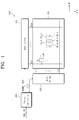
- FIG. 1 is a block diagram showing a display apparatus 1000 according to an exemplary embodiment of the present disclosure.
- the display apparatus 1000 includes a display panel 100, a timing controller 200, a gate driver 300, and a data driver 400.
- the display panel 100 displays an image.
- the display panel 100 may be any one of a variety of display panels, such as a liquid crystal display panel, an organic light emitting display panel, an electrophoretic display panel, an electrowetting display panel, etc.
- the display apparatus 1000 does not require a backlight unit (not shown) that supplies a light to the display panel 100.
- the display apparatus 1000 may further include a backlight unit (not shown) to supply light to the display panel 100.
- the display panel 100 includes a plurality of gate lines GL1 to GLk extending in a first direction DR1, and a plurality of data lines DL1 to DLm extending in a second direction DR2 crossing the first direction DR1.
- the display panel 100 includes a plurality of sub-pixels SP.
- Each of the sub-pixels SP is connected to a corresponding gate line of the gate lines GL1 to GLk and a corresponding data line of the data lines DL1 to DLm.
- FIG. 1 shows the sub-pixel SP connected to the first gate line GL1 and the first data line DL1 as a representative example.
- the display panel 100 includes a plurality of pixels PX_A and PX_B.
- Each of the pixels PX_A and PX_B includes (x.5) sub-pixels ("x" is a natural number). That is, each of the pixels PX_A and PX_B includes x normal sub-pixels SP_N and a predetermined portion of one shared sub-pixel SP_S. The two sub-pixels PX_A and PX_B share one shared sub-pixel SP_S. This will be described in further detail below.
- the timing controller 200 receives input data RGB and a control signal CS from an external graphic controller (not shown).
- the input data RGB includes red, green, and blue image data.
- the control signal CS includes a vertical synchronization signal as a frame distinction signal, a horizontal synchronization signal as a row distinction signal, and a data enable signal maintained at a high level during a period in which data are output, to indicate a data input period.
- the timing controller 200 generates data corresponding to the sub-pixels SP on the basis of the input data RGB, and converts a data format of the generated data to a data format appropriate to an interface between the timing controller 200 and the data driver 400.
- the timing controller 200 applies the converted output data RGBWf to the data driver 400.
- the timing controller 200 performs a rendering operation on the input data RGB to generate the data corresponding to the format of sub-pixels SP.
- the timing controller 200 generates a gate control signal GCS and a data control signal DCS on the basis of the control signal CS.
- the timing controller 200 applies the gate control signal GCS to the gate driver 300 and applies the data control signal DCS to the data driver 400.
- the gate control signal GCS is used to drive the gate driver 300 and the data control signal DCS is used to drive the data driver 400.
- the gate driver 300 generates gate signals in response to the gate control signal GCS and applies the gate signals to the gate lines GL1 to GLk.
- the gate control signal GCS includes a scan start signal indicating a start of scanning, at least one clock signal controlling an output period of a gate on voltage, and an output enable signal controlling the maintaining of the gate on voltage.
- the data driver 400 generates grayscale voltages in accordance with the converted output data RGBWf in response to the data control signal DCS, and applies the grayscale voltages to the data lines DL1 to DLm as data voltages.
- the data control signal DCS includes a horizontal start signal indicating a start of transmitting of the converted output data RGBWf to the data driver 400, a load signal indicating application of the data voltages to the data lines DL1 to DLm, and an inversion signal (which corresponds to the liquid crystal display panel) inverting a polarity of the data voltages with respect to a common voltage.
- Each of the timing controller 200, the gate driver 300, and the data driver 400 is directly mounted on the display panel 100 in one integrated circuit chip package or more, attached to the display panel 100 in a tape carrier package form after being mounted on a flexible printed circuit board, or mounted on a separate printed circuit board.
- at least one of the gate driver 300 and the data driver 400 may be directly integrated into the display panel 100 together with the gate lines GL1 to GLk and the data lines DL1 to DLm.
- the timing controller 200, the gate driver 300, and the data driver 400 may be integrated with each other into a single chip.
- one pixel includes two and a half sub-pixels or one and a half sub-pixels.
- one pixel includes two and a half sub-pixels
- the case that one pixel includes two and a half sub-pixels will be described in more detail, and then the case that one pixel includes one and a half sub-pixels will be described in further detail.
- FIG. 2 is a view showing a portion of the display panel 100 shown in FIG. 1 according to an exemplary embodiment of the present disclosure.
- the display panel 100 includes the sub-pixels R, G, B, and W.
- the sub-pixels R, G, B, and W display primary colors.
- the primary colors are configured to include red, green, blue, and white colors.
- the sub-pixels R, G, B, and W are configured to include a red sub-pixel R, a green sub-pixel G, a blue sub-pixel B, and a white sub-pixel W.
- the primary colors should not be limited to the above-mentioned colors. That is, the primary colors may further include yellow, cyan, and magenta colors, or any other sets of colors that can be considered as color primaries.
- the sub-pixels are repeatedly arranged in sub-pixel groups (SPGs) each configured to include eight sub-pixels arranged in two rows by four columns.
- SPGs sub-pixel groups
- Each sub-pixel group SPG includes two red sub-pixels R, two green sub-pixels G, two blue sub-pixels B, and two white sub-pixels W.
- the sub-pixels in a first row are arranged along the first direction DR1 in order of the red, green, blue, and white sub-pixels R, G, B, and W.
- the sub-pixels in a second row are arranged along the first direction DR1 in order of the blue, white, red, and green sub-pixels B, W, R, and G.
- the arrangement order of the sub-pixels of the sub-pixel group SPG should not be limited thereto or thereby. Any order of sub-pixels of any color is contemplated.
- the display panel 100 includes pixel groups PG1 to PG4. Each of the pixel groups PG1 to PG4 includes two pixels adjacent to each other.
- FIG. 2 shows four pixel groups PG1 to PG4 as a representative example.
- the pixel groups PG1 to PG4 each have the same structure except for the arrangement order of the sub-pixels included therein.
- a first pixel group PG1 will be described in further detail.
- the first pixel group PG1 includes a first pixel PX1 and a second pixel PX2 adjacent to the first pixel PX1 along the first direction DR1.
- the first pixel PX1 and the second pixel PX2 are displayed with different hatch patterns.
- the display panel 100 includes a plurality of pixel areas PA1 and PA2, in which the pixels PX1 and PX2 are disposed, respectively.
- the pixels PX1 and PX2 exert influence on a resolution of the display panel 100 and the pixel areas PA1 and PA2 refer to areas in which the pixels are disposed.
- Each of the pixel areas PA1 and PA2 displays three different colors.
- Each of the pixel areas PA1 and PA2 corresponds to an area in which a ratio, e.g., an aspect ratio, of a length along the first direction DR1 to a length along the second direction DR2 is 1:1. That is, each pixel area PA1, PA2 is a square-shaped area.
- one pixel may include a portion of one sub-pixel due to the shape (aspect ratio) of the pixel area.
- one independent sub-pixel e.g., the blue sub-pixel B of the first pixel group PG1 is not fully included in one pixel. That is, part of one independent sub-pixel, e.g., the blue sub-pixel B of the first pixel group PG1, may be included in one pixel, and another part of this blue sub-pixel B may belong to another pixel.
- the first pixel PX1 is disposed in the first pixel area PA1 and the second pixel PX2 is disposed in the second pixel area PA2.
- n is an odd number equal to or greater than 3 sub-pixels R, G, B, W, and R are disposed in the first and second pixel areas PA1, PA2 together.
- n is 5, and thus five sub-pixels R, G, B, W, and R are disposed in the first and second pixel areas PA1 and PA2.
- sub-pixel B (hereinafter, referred to as a shared sub-pixel) along the first direction DR1 lies within both the first and second pixel areas PA1 and PA2. That is, the shared sub-pixel B is disposed at a center portion of the sub-pixels R, G, B, W, and R included in the first and second pixels PX1 and PX2 and overlaps both the first and second pixel areas PA1 and PA2.
- the first and second pixels PX1 and PX2 may share the shared sub-pixel B.
- the blue data applied to the shared sub-pixel B is generated on the basis of a first blue data corresponding to the first pixel PX1 among the input data RGB and a second blue data corresponding to the second pixel PX2 among the input data RGB.
- two pixels included in each of the second to fourth pixel groups PG2 to PG4 may share one shared sub-pixel.
- the shared sub-pixel of the first pixel group PG1 is the blue sub-pixel B
- the shared sub-pixel of the second pixel group PG2 is the white sub-pixel W
- the shared sub-pixel of the third pixel group PG3 is the red sub-pixel R
- the shared sub-pixel of the fourth pixel group PG4 is the green sub-pixel G.
- the display panel 100 includes the first to fourth pixel groups PG1 to PG4, each including two pixels adjacent to each other, and the two pixels PX1 and PX2 of each of the first to fourth pixel groups PG1 to PG4 share one sub-pixel.
- the first and second pixels PX1 and PX2 are driven during the same horizontal scanning period (1h), which corresponds to a pulse-on period of one gate signal. That is, the first and second pixels PX1 and PX2 are connected to the same gate line and driven by the same gate signal. Similarly, the first and second pixel groups PG1 and PG2 may be driven during a first horizontal scanning period and the third and fourth pixel groups PG3 and PG4 may be driven during a second horizontal scanning period.
- each of the first and second pixels PX1 and PX2 includes two and a half sub-pixels.
- the first pixel PX1 includes a red sub-pixel R, a green sub-pixel G, and a half of a blue sub-pixel B along the first direction DR1.
- the second pixel PX2 includes the other half of the blue sub-pixel B, a white sub-pixel W, and a red sub-pixel R along the first direction DR1.
- each pixel PXn is a three-color pixel.
- the first pixel PX1 displays red, green, and blue colors and the second pixel PX2 displays blue, white, and red colors.
- the number of sub-pixels may be two and a half times greater than the number of pixels.
- the two pixels PX1 and PX2 include the five sub-pixels R, G, B, W, and R.
- the five sub-pixels R, G, B, W, and R are disposed in the first and second areas PA1 and PA2, along the first direction DR1.
- FIG. 3 is a partially enlarged view showing a first pixel and a peripheral area of the first pixel shown in FIG. 2 .
- FIG. 3 shows data lines DLj to DLj+3 (1 ⁇ j ⁇ m) adjacent to each other along the first direction DR1 and gate lines GLi and GLi+1 (1 ⁇ i ⁇ k) adjacent to each other along the second direction DR1.
- a thin film transistor and an electrode connected to the thin film transistor may be disposed in areas partitioned by the data lines DLj to DLj+3 (1 ⁇ j ⁇ m) and the gate lines GLi and GLi+1 (1 ⁇ i ⁇ k).
- each of the first and second pixels PX1 and PX2 has the aspect ratio of 1:1, i.e., the ratio of the length W1 along the first direction DR1 to the length W3 along the second direction DR2.
- the term “substantially” means that the aspect ratio varies depending on factors such as a process condition or a device state.
- the first pixel PX1 will be described in further detail below, as being exemplary of both pixels PX1 and PX2.
- the length W1 along the first direction DR1 of the first pixel PX1 is two and a half times greater than a distance W2 between a center in width of the j-th data line DLj along the first direction DR1 and a center in width of the (j+1)th data line DLj+1 along the first direction DR2.
- the length W1 along the first direction DR1 of the first pixel PX1 is equal to a sum of a distance between the center in width of the j-th data line DLj along the first direction DR1 and a center in width of the (j+2)th data line DLj+2 along the first direction DR1, plus a half of the distance between the center in width of the (j+2)th data line DLj+2 along the first direction DR1 and a center in width of the (j+3)th data line DLj+3 along the first direction DR1, but it should not be limited thereto or thereby.
- the length W1 along the first direction DR1 of the first pixel PX1 may correspond to a half of a distance between the center in width of the j-th data line DLj along the first direction DR1 and a center in width of a (j+5)th data line along the first direction DR1.
- the length W3 along the second direction DR2 of the first pixel PX1 is defined by a distance between a center in width of the i-th gate line GLi along the second direction DR2 and a center in width of the (i+1)th gate line GLi+1 along the second direction DR2, but it should not be limited thereto or thereby. That is, the length W3 along the second direction DR2 of the first pixel PX1 is defined by a half of a distance between the center in width of the i-th gate line GLi along the second direction DR2 and a center in width of the (i+2)th gate line along the second direction DR2.
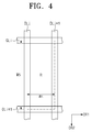
- FIG. 4 is a partially enlarged view showing one sub-pixel, e.g., the red sub-pixel, and a peripheral area of the red sub-pixel shown in FIG. 2 .
- FIG. 4 shows data lines DLj and DLj+1 (1 ⁇ j ⁇ m) adjacent to each other along the first direction DR1, and gate lines GLi and GLi+1 (1 ⁇ i ⁇ k) adjacent to each other along the second direction DR2.
- a thin film transistor and an electrode connected to the thin film transistor may be disposed in areas partitioned by the data lines DLj and DLj+1 (1 ⁇ j ⁇ m) and the gate lines GLi and GLi+1 (1 ⁇ i ⁇ k).
- each of the sub-pixels R, G, B, and W has an aspect ratio of 1:2.5, i.e., the ratio of the length W4 along the first direction DR1 to the length W5 along the second direction DR2.
- the term “substantially” means that the aspect ratio can vary somewhat depending on factors such as a process condition or a device state.
- the sub-pixels R, G, B, and W since the sub-pixels R, G, B, and W have largely the same structure and function, only the red sub-pixel R will be described in detail.
- the length W4 along the first direction DR1 of the red sub-pixel R is defined by a distance W4 between a center in width of the j-th data line DLj along the first direction DR1 and a center in width of the (j+1)th data line DLj+1 along the first direction DR1, but it should not be limited thereto or thereby. That is, the length W4 along the first direction DR1 of the red sub-pixel R may be defined by a half of a distance between the center in width of the j-th data line DLj along the first direction DR1 and a center in width of the (j+2)th data line along the first direction DR1.
- the length W5 along the second direction DR2 of the red sub-pixel R is defined by a distance between a center in width of the i-th gate line GLi along the second direction DR2 and a center in width of the (i+1)th gate line GLi+1 along the second direction DR2, but it should not be limited thereto or thereby. That is, the length W5 along the second direction DR2 of the red sub-pixel R may be defined by a half of a distance between the center in width of the i-th gate line GLi along the second direction DR2 and a center in width of the (i+2)th gate line along the second direction DR2.
- the sub-pixels arranged in two rows by five columns may have a substantially square shape. That is, the sub-pixels included in the first and third pixel groups PG1 and PG3 collectively may have a square shape.
- each of the first to fourth pixel groups PG1 to PG4 has an aspect ratio of 2:1.
- the first pixel group PG1 includes n (n is an odd number equal to or larger than 3) sub-pixels R, G, B, W, and R.
- Each of the sub-pixels R, G, B, W, and R included in the first pixel group PG1 has an aspect ratio of 2:n. Since the "n" is 5 in the exemplary embodiment shown in FIG. 2 , the aspect ratio of each of the sub-pixels R, G, B, W, and R is 1:2.5.
- the display apparatus of the present disclosure since the one pixel includes two and a half (2.5) sub-pixels, the number of data lines in the display apparatus may be reduced by a factor of 5/6 relative to a conventional RGB stripe display, even though the display apparatus displays the same resolution as that of the RGB stripe structure.
- the circuit configuration of the data driver 400 (refer to FIG. 1 ) becomes simpler, and thus a manufacturing cost of the data driver 400 is reduced.
- the aperture ratio of the display apparatus is increased since the number of data lines is reduced.
- one pixel displays three colors. Therefore, the display apparatus may have improved color reproducibility even though the display apparatus has the same resolution as that of a structure in which one pixel includes two sub-pixels from among red, green, blue, and white sub-pixels R, G, B, and W.
- FIG. 5 is a block diagram showing the timing controller 200 shown in FIG. 1 .
- the timing controller 200 includes a gamma compensating part 211, a gamut mapping part 213, a sub-pixel rendering part 215, and a reverse gamma compensating part 217.
- the gamma compensating part 211 receives input data RGB including red, green, and blue data.
- the input data RGB have a non-linear characteristic.
- the gamma compensating part 211 applies a gamma function to the input data RGB to allow the input data RGB to be linearized.
- the gamma compensating part 211 generates the linearized input data RGB' on the basis of the input data RGB having the non-linear characteristic, such that the data is easily processed by subsequent blocks, e.g., the gamut mapping part 213 and the sub-pixel rendering part 215.
- the linearized input data RGB' is applied to the gamut mapping part 213.
- the gamut mapping part 213 generates RGBW data RGBW having red, green, blue, and white data on the basis of the linearized input data RGB'.
- the gamut mapping part 213 maps an RGB gamut of the input data RGB' linearized by a gamut mapping algorithm (GMA) to an RGBW gamut and generates the RGBW data RGBW
- GMA gamut mapping algorithm
- the RGBW data RGBW is applied to the sub-pixel rendering part 215.
- the gamut mapping part 213 may further generate a brightness data of the linearized input data RGB' in addition to the RGBW data RGBW.
- the brightness data is applied to the sub-pixel rendering part 215 and used for a sharpening filtering process.
- the sub-pixel rendering part 215 performs a rendering operation on the RGBW data RGBW to generate rendering data RGBW2 respectively corresponding to the sub-pixels R, G, B, and W.
- the RGBW data RGBW include data about four colors configured to include red, green, blue, and white colors corresponding to each pixel area.
- the rendering data RGBW2 may only include data for three colors among the red, green, blue, and white colors.
- the rendering operation performed by the sub-pixel rendering part 215 is configured to include a re-sample filtering process and a sharpening filtering operation.
- the re-sample filtering operation modifies the color of the target pixel, on the basis of color values of the target pixel and neighboring pixels disposed adjacent to the target pixel.
- the sharpening filtering operation detects shape of the image, e.g., lines, edges, dots, diagonal lines, etc., and position of the RGBW data RGBW, and compensates for the RGBW data RGBW on the basis of the detected data.
- shape of the image e.g., lines, edges, dots, diagonal lines, etc.
- the rendering data RGBW2 is applied to the reverse gamma compensating part 217.
- the reverse gamma compensating part 217 performs a reverse gamma compensation operation on the rendering data RGBW2, to convert the rendering data RGBW2 to non-linearized RGBW data RGBW'.
- the data format of the non-linearized RGBW data RGBW' is converted to an output data RGBWf by taking a specification of the data driver 400 into consideration in known manner, and the output data RGBWf is applied to the data driver 400.
- FIG. 6 is a block diagram showing the sub-pixel rendering part 215 shown in FIG. 5 .
- the sub-pixel rendering part 215 includes a first rendering part 2151 and a second rendering part 2153.
- the first rendering part 2151 generates an intermediate rendering data RGBW1 corresponding to the sub-pixels of each pixel on the basis of the RGBW data RGBW using a re-sample filter.
- the RGBW data RGBW includes red, green, blue, and white data corresponding to each pixel area.
- the intermediate rendering data RGBW1 includes two normal sub-pixel data and a shared sub-pixel data, which collectively correspond to a pixel area.
- the shared sub-pixel data is area portion of the image data for the shared sub-pixel.
- a maximum grayscale value of the portion of the shared sub-pixel data corresponding to each pixel may be smaller than a maximum grayscale value of the normal sub-pixel data.
- the grayscale of the portion of the shared sub-pixel data and the grayscale of the normal sub-pixel data may be determined by a scale coefficient of the re-sample filter.
- FIG. 7 is a view showing pixel areas arranged in three rows by four columns, according to an exemplary embodiment of the present disclosure
- FIG. 8 is a view showing a first pixel disposed in the fifth pixel area shown in FIG. 7
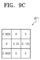
- FIGS. 9A to 9C are views showing a re-sample filter used to generate the first pixel data shown in FIG. 8 .
- FIG. 8 shows the first pixel PX1 configured to include a red sub-pixel R1, a green sub-pixel G1, and a blue sub-pixel B1 as a representative example.
- the red sub-pixel R1 may be referred to as a first normal sub-pixel
- the green sub-pixel G1 may be referred to as a second normal sub-pixel
- the blue sub-pixel B1 may be referred to as a first shared sub-pixel.
- Each of a red sub-pixel R1 (first normal sub-pixel) and a green sub-pixel G1 (second normal sub-pixel) is included in the first pixel PX1 as an independent sub-pixel.
- the blue sub-pixel B1 (first shared sub-pixel) corresponds to a portion of the shared sub-pixel.
- the blue sub-pixel B1 does not serve as an independent sub-pixel and is to process the data of the portion of the shared sub-pixel included in the first pixel PX1. That is, the blue sub-pixel B1 of the first pixel PX1 forms one independent shared sub-pixel together with a blue sub-pixel B2 of the second pixel PX2.
- the first pixel data is configured to include a first normal sub-pixel data corresponding to the first normal sub-pixel R1, a second normal sub-pixel data corresponding to the second normal sub-pixel G1, and a first shared sub-pixel data corresponding to the first shared sub-pixel B1.
- the first pixel data is generated from the RGBW data for that pixel and all immediately-surrounding pixels. That is, for pixel area PA5 of FIG. 7 , the first pixel data is generated on the basis of the data among the RGBW data RGBW, which corresponds to the fifth pixel area PA5 in which the first pixel PX1 is disposed and the pixel areas PA1 to PA4 and PA6 to PA9 surrounding the fifth pixel area PA5.
- the first to ninth pixel areas PA1 to PA9 are disposed at positions respectively defined by a first row and a first column, a second row and the first column, a third row and the first column, the first row and a second column, the second row and the second column, the third row and the second column, the first row and a third column, the second row and the third column, and the third row and the third column.
- the first pixel data may be generated on the basis of the data corresponding to the first to ninth pixel areas PA1 to PA9, but the number of the pixel areas should not be limited thereto or thereby.
- the first pixel data may be generated on the basis of the data corresponding to ten or more pixel areas.
- the re-sample filter includes a first normal re-sample filter RF1 (referring to FIG. 9A ), a second normal re-sample filter GF1 (referring to FIG. 9B ), and a first shared re-sample filter BF1 (referring to FIG. 9C ).
- the scale coefficient of the re-sample filter indicates a proportion of the RGBW data RGBW corresponding to each pixel area among one sub-pixel data.
- the scale coefficient of the re-sample filter is equal to or greater than zero (0) and smaller than one (1).
- FIG. 9A shows the first normal re-sample filter RF1 used to generate the first normal sub-pixel data of the first pixel data.
- the scale coefficients of the first normal re-sample filter RF1 in the first to ninth pixel areas PA1 to PA9 are 0, 0.125, 0, 0.0625, 0.625, 0.0625, 0.0625, 0, and 0.0625, respectively.
- the first rendering part 2151 multiplies the red data of the RGBW data RGBW, which correspond to the first to ninth pixel areas PA1 to PA9, by the scale coefficients in corresponding positions of the first normal re-sample filter RF1. For instance, the red data corresponding to the first pixel area PA1 is multiplied by the scale coefficient, e.g., 0, of the first normal re-sample filter RF1 corresponding to the first pixel area PA1, and the red data corresponding to the second pixel area PA2 is multiplied by the scale coefficient, e.g., 0.125, of the first normal re-sample filter RF1 corresponding to the second pixel area PA2. Similarly, the red data corresponding to the ninth pixel area PA9 is multiplied by the scale coefficient, e.g., 0.0625, of the first normal re-sample filter RF1 corresponding to the ninth pixel area PA9.
- the scale coefficient e.g. 0.0625
- the first rendering part 2151 calculates a sum of the values obtained by multiplying the red data of the first to ninth pixel areas PA1 to PA9 by the scale coefficients of the first normal re-sample filter RF1, and this sum is designated as the first normal sub-pixel data for the first normal sub-pixel R1 of the first pixel PX1.
- FIG. 9B shows the second normal re-sample filter GF1 used to generate the second normal sub-pixel data of the first pixel data.
- the scale coefficients of the second normal re-sample filter GF1 in the first to ninth pixel areas PA1 to PA9 are 0, 0, 0, 0.125, 0.625, 0.125, 0, 0.125, and 0, respectively.
- the first rendering part 2151 multiplies the green data of the RGBW data RGBW for the first to ninth pixel areas PA1 to PA9, by the scale coefficients in corresponding positions of the second normal re-sample filter GF1. It then calculates a sum of the multiplied values as the second normal sub-pixel data for the second normal sub-pixel G1.
- the rendering operation that calculates the second normal sub-pixel data is substantially similar to that of the first normal sub-pixel data, and thus details thereof will be omitted.
- FIG. 9C shows the first shared re-sample filter BF1 used to generate the first shared sub-pixel data of the first pixel data.
- the scale coefficients of the first shared re-sample filter BF1 in the first to ninth pixel areas PA1 to PA9 are 0.0625, 0, 0.0625, 0, 0.25, 0, 0, 0.125, and 0, respectively.
- the first rendering part 2151 multiplies the blue data of the RGBW data RGBW, which correspond to the first to ninth pixel areas PA1 to PA9, by the scale coefficients in corresponding positions of the first shared re-sample filter BF1. It then calculates a sum of the multiplied values as the first shared sub-pixel data for the first shared sub-pixel B1.
- the rendering operation that calculates the first shared sub-pixel data is substantially similar to that of the first normal sub-pixel data, and thus details thereof will be omitted.
- FIG. 10 is a view showing the second pixel disposed in the eighth pixel area shown in FIG. 7
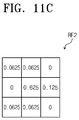
- FIGS. 11A to 11C are views showing a re-sample filter used to generate a second pixel data shown in FIG. 10 .
- FIG. 10 shows the second pixel PX2 configured to include a blue sub-pixel B2, a white sub-pixel W2, and a red sub-pixel R2 as a representative example.
- the white sub-pixel W2 may be referred to as a third normal sub-pixel
- the red sub-pixel R2 may be referred to as a fourth normal sub-pixel
- the blue sub-pixel B2 may be referred to as a second shared sub-pixel.
- Each of a white sub-pixel W2 (third normal sub-pixel) and a red sub-pixel R2 (fourth normal sub-pixel) is included in the second pixel PX2 as an independent sub-pixel.
- the blue sub-pixel B2 (second shared sub-pixel) corresponds to a remaining portion of the independent shared blue sub-pixel B1 of the first pixel PX1.
- the blue sub-pixel B2 of the second pixel PX2 forms the independent shared sub-pixel together with the blue sub-pixel B1 of the first pixel PX1.
- the second pixel data is configured to include a second shared sub-pixel data corresponding to the second shared sub-pixel B2, a third normal sub-pixel data corresponding to the third normal sub-pixel W2, and a fourth normal sub-pixel data corresponding to the fourth normal sub-pixel R2.
- the second pixel data is generated on the basis of the data among the RGBW data RGBW, which corresponds to the eighth pixel area PA8 in which the second pixel PX2 is disposed, as well as the pixel areas PA4 to PA7 and PA9 to PA12 surrounding the eighth pixel area PA8.
- the fourth to twelfth pixel areas PA4 to PA12 are disposed at positions respectively defined by a first row and a first column, a second row and the first column, a third row and the first column, the first row and a second column, the second row and the second column, the third row and the second column, the first row and a third column, the second row and the third column, and the third row and the third column.
- the second pixel data may be generated on the basis of the data corresponding to the fourth to twelfth pixel areas PA4 to PA12, but the number of the pixel areas should not be limited thereto or thereby.
- the second pixel data may be generated on the basis of the data corresponding to any pixels and any number of pixels, for example ten or more pixel areas.
- the re-sample filter includes a second shared re-sample filter BF2 (referring to FIG. 11A ), a third normal re-sample filter WF2 (referring to FIG. 11B ), and a fourth normal re-sample filter RF2 (referring to FIG. 11C ).
- the scale coefficient of the re-sample filter indicates a proportion of the RGBW data RGBW corresponding to each pixel area among one sub-pixel data.
- the scale coefficient of the re-sample filter is equal to or greater than zero (0) and smaller than one (1).
- FIG. 11A shows the second shared re-sample filter BF2 used to generate the second shared sub-pixel data of the second pixel data.
- the scale coefficients of the second shared re-sample filter BF2 in the fourth to twelfth pixel areas PA4 to PA12 are 0, 0.125, 0, 0, 0.25, 0, 0.0625, 0, and 0.0625, respectively.
- the first rendering part 2151 multiplies the blue data of the RGBW data RGBW, which correspond to the fourth to twelfth pixel areas PA4 to PA12, by the scale coefficients in corresponding positions of the second shared re-sample filter BF2. It then calculates a sum of the multiplied values as the second shared sub-pixel data for the second shared sub-pixel B2.
- the rendering operation that calculates the second shared sub-pixel data is substantially similar to that of the first shared sub-pixel data of the first pixel data, and thus details thereof will be omitted.
- FIG. 11B shows the third normal re-sample filter WF2 used to generate the third normal sub-pixel data of the second pixel data.
- the scale coefficients of the third normal re-sample filter WF2 in the fourth to twelfth pixel areas PA4 to PA12 are 0, 0.125, 0, 0.125, 0.625, 0.125, 0, 0, and 0, respectively.
- the first rendering part 2151 multiplies the white data of the RGBW data RGBW, which correspond to the fourth to twelfth pixel areas PA4 to PA12, by the scale coefficients in corresponding positions of the third normal re-sample filter WF2. It then calculates a sum of the multiplied values as the third normal sub-pixel data for the third normal sub-pixel W2.
- the rendering operation that calculates the third normal sub-pixel data is substantially similar to that of the first normal sub-pixel data of the first pixel data, and thus details thereof will be omitted.
- FIG. 11C shows the fourth normal re-sample filter RF2 used to generate the third normal sub-pixel data of the second pixel data.
- the scale coefficients of the fourth normal re-sample filter RF2 in the fourth to twelfth pixel areas PA4 to PA12 are 0.0625, 0, 0.0625, 0.0625, 0.625, 0.0625, 0, 0.125, and 0, respectively.
- the first rendering part 2151 multiplies the red data of the RGBW data RGBW, which correspond to the fourth to twelfth pixel areas PA4 to PA12, by the scale coefficients in corresponding positions of the fourth normal re-sample filter RF2. It then calculates a sum of the multiplied values as the fourth normal sub-pixel data for the fourth normal sub-pixel R2.
- the rendering operation that calculates the fourth normal sub-pixel data is substantially similar to that of the first normal sub-pixel data of the first pixel data, and thus details thereof will be omitted.
- the scale coefficients of the re-sample filter are determined by taking the area of the corresponding sub-pixel in each pixel into consideration.
- the first and second pixels PX1 and PX2 will be described as a representative example.
- the area of each of the first and second normal sub-pixels R1 and G1 is greater than that of the shared half of the first shared sub-pixel B1.
- the area of each of the first and second normal sub-pixels R1 and G1 is two times greater than that of the shared portion of the first shared sub-pixel B1 in the first pixel PX1.
- a sum of the scale coefficients of the first shared re-sample filter BF1 may be a half of the sum of the scale coefficients of the first normal re-sample filter RF1.
- a sum of the scale coefficients of the first shared re-sample filter BF1 may be a half of the sum of the scale coefficients of the second normal re-sample filter GF1.
- the sum of the scale coefficients of each of the first and second normal re-sample filters RF1 and GF1 is 1 and the sum of the scale coefficients of the first shared re-sample filter BF1 is 0.5.
- the maximum grayscale of the first shared sub-pixel data corresponds to a half of the maximum grayscale of each of the first and second normal sub-pixel data.
- the area of each of the third and fourth normal sub-pixels W2 and R2 is greater than that part of the second shared sub-pixel B2 that lies within pixel PX2.
- the area of each of the third and fourth normal sub-pixels W2 and R2 is two times greater than that of the second shared sub-pixel B2 within the second pixel PX2.
- a sum of the scale coefficients of the second shared re-sample filter BF2 may be a half of the sum of the scale coefficients of the third normal re-sample filter WF2.
- a sum of the scale coefficients of the second shared re-sample filter BF2 may be a half of the sum of the scale coefficients of the fourth normal re-sample filter RF2.
- the sum of the scale coefficients of each of the third and fourth normal re-sample filters WF2 and RF2 is 1 and the sum of the scale coefficients of the second shared re-sample filter BF2 is 0.5.
- the maximum grayscale of the second shared sub-pixel data corresponds to a half of the maximum grayscale of each of the third and fourth normal sub-pixel data.
- the second rendering part 2153 calculates the first and second shared sub-pixel data of the intermediate rendering data RGBW1 to generate a shared sub-pixel data.
- the shared sub-pixel data corresponds to one independent shared sub-pixel configured to include the first and second shared sub-pixels B1 and B2.
- the second rendering part 2153 may generate the shared sub-pixel data by adding the first shared sub-pixel data of the first pixel data and the second shared sub-pixel data of the second pixel data.
- a maximum grayscale of the data for the shared sub-pixel i.e., the blue sub-pixel B1 of the first pixel PX1 and the blue sub-pixel B2 of the second pixel PX2, may be substantially the same as the maximum grayscale of the data of each of the first to fourth normal sub-pixels R, G1, W2, and R2.
- Adding the sum of the scale coefficients of the first shared re-sample filter BF1 applied to the first pixel PX1 and the sum of the scale coefficients of the second shared re-sample filter BF2 produces 1, and a sum of the scale coefficients of other re-sample filters RF1, GF1, WF2, and RF2 is each also 1.
- the second rendering part 2153 outputs the data for the first to fourth normal sub-pixels R1, G1, W2, and R2 and the shared sub-pixel data as the rendering data RGBW2.
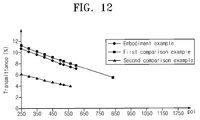
- FIG. 12 is a graph showing a transmittance as a function of a pixel density (hereinafter, referred to as a pixel per inch (ppi)), for the display apparatus including the display panel shown in FIG. 2 , a first comparison example, and a second comparison example.
- ppi pixel per inch
- Table 1 shows the transmittance as a function of ppi for the display apparatus including the display panel shown in FIG. 2 , the first comparison example, and the second comparison example.
- the first comparison example indicates a structure in which one pixel is configured to include two RGBW sub-pixels along the first direction DR1
- the second comparison example indicates an RGB stripe structure in which one pixel is configured to include three sub-pixels along the first direction DR1.
- a maximum ppi of the embodiment example, the first comparison example, and the second comparison example indicates a value measured when a process threshold value in a short side (a length along the first direction DR1 of each sub-pixel in the display panel shown in FIG. 2 ) of each sub-pixel is set to about 15 micrometers.
- the display apparatus including the display panel shown in FIG. 2 has a maximum ppi higher than that of the second comparison example under comparable conditions.
- the display apparatus according to the present disclosure has a maximum ppi of about 600 and the second comparison example has a maximum ppi of about 564.
- the display apparatus of the embodiment example has substantially the same maximum ppi as that of the second comparison example, the display apparatus has transmittance higher than that of the second comparison example.
- the display apparatus of the embodiment example has a transmittance of about 7.1% and the second comparison example has a transmittance of about 3.98%.
- the display apparatus of the embodiment example may have a color reproducibility higher than that of the first comparison example.
- FIG. 13 is a view showing a portion of a display panel 101 according to another exemplary embodiment of the present disclosure.
- the display panel 101 shown in FIG. 13 has substantially the same structure and function as those of the display panel 100 shown in FIG. 2 , except for the difference in color arrangement of the sub-pixels.
- features of the display panel 101 shown in FIG. 13 that differ from the display panel 100 shown in FIG. 2 will mainly be described.
- the sub-pixels R, G, B, and W are repeatedly arranged within the sub-pixel group SPG, which is configured to include ten sub-pixels arranged in two rows by five columns.
- the sub-pixel group SPG includes two red sub-pixels, two green sub-pixels, two blue-sub pixels, and four white sub-pixels.
- the sub-pixels arranged in the first row of the sub-pixel group SPG are arranged in order of a red sub-pixel R, a green sub-pixel G, a white sub-pixel W, a blue sub-pixel B, and a white sub-pixel W along the first direction DR1.
- the sub-pixels arranged in the second row of the sub-pixel group SPG are arranged in order of a blue sub-pixel B, a white sub-pixel W, a white sub-pixel W, a red sub-pixel R, and a green sub-pixel G along the first direction DR1.
- the arrangement order of the sub-pixels should not be limited to the above-mentioned orders.
- the shared sub-pixel in the first pixel group PG1 displays a white color and the shared sub-pixel in the second pixel group PG2 also displays a white color. That is, the shared sub-pixel of the display panel 101 shown in FIG. 13 may be a white sub-pixel displaying a white color.
- the number of white sub-pixels is increased compared with that of the display panel 100 shown in FIG. 2 , and thus the overall brightness of the display panel 101 may be improved.
- the area of the white sub-pixel in each pixel is decreased compared with structures in which one pixel includes two RGBW sub-pixels. Accordingly, a ratio of the white color to the yellow color (Y/W) may be prevented from decreasing since the white sub-pixel is added to the sub-pixel group SPG
- FIG. 14 is a view showing a portion of a display panel 102 according to another exemplary embodiment of the present disclosure.
- the display panel 102 shown in FIG. 14 has substantially the same structure and function as those of the display panel 100 shown in FIG. 2 , except for the difference in color arrangement of the sub-pixels.
- features of the display panel 102 shown in FIG. 14 that differ from those of the display panel 100 shown in FIG. 2 will mainly be described.
- the sub-pixels R, G, B, and W are repeatedly arranged within sub-pixel group SPG, which is configured to include ten sub-pixels arranged in two rows by five columns.
- the sub-pixel group SPG includes three red sub-pixels, three green sub-pixels, two blue-sub pixels, and two white sub-pixels.
- the sub-pixels arranged in the first row of the sub-pixel group SPG are arranged in order of a red sub-pixel R, a green sub-pixel G, a white sub-pixel W, a blue sub-pixel B, and a red sub-pixel R along the first direction DR1.
- the sub-pixels arranged in the second row of the sub-pixel group SPG are arranged in order of a green sub-pixel G, a blue sub-pixel B, a white sub-pixel W, a red sub-pixel R, and a green sub-pixel G along the first direction DR1.
- the arrangement order of the sub-pixels should not be limited to that shown.
- the shared sub-pixel in the first pixel group PG1 displays a white color and the shared sub-pixel in the second pixel group PG2 also displays a white color. That is, the shared sub-pixel of the display panel 102 shown in FIG. 14 may be a white sub-pixel displaying a white color.
- the display panel 102 shown in FIG. 14 since two pixels of each pixel group share a white sub-pixel in the display panel 102 shown in FIG. 14 , the area of the white sub-pixel in each pixel is decreased compared with structures in which one pixel includes two RGBW sub-pixels. Accordingly, a ratio of the white color to the yellow color (Y/W) may be prevented from decreasing since the white sub-pixel is added to the sub-pixel group SPG
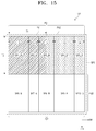
- FIG. 15 is a view showing a portion of a display panel 103 according to another exemplary embodiment of the present disclosure.
- the display panel 103 shown in FIG. 15 has substantially the same structure and function as those of the display panel 100 shown in FIG. 2 , except for the difference in color arrangement and shape of the sub-pixels.
- features of the display panel 103 shown in FIG. 15 that differ from those of the display panel 100 shown in FIG. 2 will mainly be described.
- sub-pixels SP1_R to SP10_G are repeatedly arranged within sub-pixel group SPG, which is configured to include ten sub-pixels arranged in two rows by five columns.
- the sub-pixel group SPG includes two red sub-pixels, four green sub-pixels, two blue-sub pixels, and two white sub-pixels.
- the sub-pixels arranged in the first row of the sub-pixel group SPG are arranged in order of a first sub-pixel SP1_R, a second sub-pixel SP2_G, a third sub-pixel SP3_W, a fourth sub-pixel SP4_B, and a fifth sub-pixel SP5_G along the first direction DR1.
- the first sub-pixel SP1_R displays a red color
- the second sub-pixel SP2_G displays a green color
- the third sub-pixel SP3_W displays a white color
- the fourth sub-pixel SP4_B displays a blue color
- the fifth sub-pixel SP5 G displays a green color.
- the sub-pixels arranged in the second row of the sub-pixel group SPG are arranged in order of a sixth sub-pixel SP6_B, a seventh sub-pixel SP7_G, an eighth sub-pixel SP8_W, a ninth sub-pixel SP9_R, and a tenth sub-pixel SP10_G along the first direction DR1.
- the sixth sub-pixel SP6_B displays a blue color
- the seventh sub-pixel SP7_G displays a green color
- the eighth sub-pixel SP8_W displays a white color
- the ninth sub-pixel SP9_R displays a red color
- the tenth sub-pixel SP10_G displays a green color.
- the arrangement order of the colors of the first to tenth sub-pixels SP1_R to SP10_G should not be limited to that shown.
- the display panel 103 includes pixel groups PG1 and PG2, each including two pixels adjacent to each other.
- FIG. 15 shows two pixel groups as a representative example.
- the pixel groups PG1 and PG2 have substantially the same structure except for the difference in color arrangement of the sub-pixels thereof.
- the first pixel group PG1 will be described in further detail as an illustrative example.
- the first pixel group PG1 includes a first pixel PX1 and a second pixel PX2, which are disposed adjacent to each other along the first direction DR1.
- the first and second pixels PX1 and PX2 share the third sub-pixel SP3_W
- the third sub-pixel SP3_W shared in the first pixel group PG1 displays a white color.
- the eighth sub-pixel SP8_W shared in the second pixel group PG2 displays a white color. That is, the shared sub-pixel of the display panel 103 shown in FIG. 15 may be a white sub-pixel.
- each of the first and second pixels PX1 and PX2 includes two and a half sub-pixels.
- the first pixel PX1 includes the first sub-pixel SP1_R, the second sub-pixel SP2_G, and a half of the third sub-pixel SP3_W, which are arranged along the first direction DR1.
- the second pixel PX2 includes the remaining half of the third sub-pixel SP3_W, the fourth sub-pixel SP4_B, and the fifth sub-pixel SP5_G, which are arranged along the first direction DR1.
- the number of sub-pixels may be two and a half times greater than the number of pixels.
- the first and second pixels PX1 and PX2 are configured to collectively include five sub-pixels SP1_R, SP2_G, SP3_W, SP4_B, and SP5_G.
- the aspect ratio i.e., a ratio of a length T1 along the first direction DR1 to a length T2 along the second direction DR2, of each of the first and second pixels PX1 and PX2 is substantially 1:1.
- the aspect ratio of each of the first and second pixel groups PG1 and PG2 is substantially 2:1.
- the aspect ratio i.e., a ratio of a length T3 along the first direction DR1 to a length T2 along the second direction DR2, of each of the first sub-pixel SP1_R, the fourth sub-pixel SP4_B, the sixth sub-pixel SP6_B, and the ninth sub-pixel SP9_R is substantially 2:3.75.
- the aspect ratio i.e., a ratio of a length T4 along the first direction DR1 to the length T2 along the second direction DR2, of each of the second sub-pixel SP2_G, the fifth sub-pixel SP5_G, the seventh sub-pixel SP7_G, and the tenth sub-pixel SP10_G is substantially 1:3.75.
- the aspect ratio i.e., a ratio of a length T5 along the first direction DR1 to the length T2 along the second direction DR2, of each of the third sub-pixel SP3_W and the eighth sub-pixel SP8_W is substantially 1.5:3.75.
- the process of generating data applied to the display panel 103 shown in FIG. 15 is substantially similar to the process described with reference to FIGS. 5 to 11C , and thus detailed descriptions of the rendering operation will be omitted.
- the display panel 103 shown in FIG. 15 two pixels of each pixel group share a white sub-pixel. Accordingly, the brightness of the display panel 103 may be increased as compared with an RGB stripe structure in which one pixel includes three RGB sub-pixels, and as compared with a structure in which one pixel includes RG sub-pixels or BG sub-pixels. In addition, since one pixel of the display panel 103 shown in FIG. 15 includes two and a half sub-pixels, the aperture ratio and the light transmittance of the display panel 103 may be increased as compared with the structure in which one pixel includes three or more sub-pixels.
- FIG. 16 is a view showing a portion of a display panel 104 according to another exemplary embodiment of the present disclosure.
- the long side of the sub-pixel extends along the first direction DR1 and two pixels adjacent to each other along the second direction DR2 share a shared sub-pixel.
- features of the display panel 104 shown in FIG. 16 that differ from the display panel 100 shown in FIG. 2 will be described in further detail.
- sub-pixels R, G, B, and W are repeatedly arranged within sub-pixel group SPG, which is configured to include eight sub-pixels arranged in four rows by two columns.
- the sub-pixel group SPG includes two red sub-pixels R, two green sub-pixels G, two blue-sub pixels B, and two white sub-pixels W.
- the sub-pixels arranged in the first column of the sub-pixel group SPG are arranged in order of a red sub-pixel R, a green sub-pixel G, a blue sub-pixel B, a white sub-pixel W along the second direction DR2.
- the sub-pixels arranged in the second column of the sub-pixel group SPG are arranged in order of a blue sub-pixel B, a white sub-pixel W, a red sub-pixel R, a green sub-pixel G along the second direction DR2.
- the arrangement of the colors of the sub-pixels should not be limited to that shown.
- the display panel 104 includes pixel groups PG1 and PG2, each including two pixels adjacent to each other.
- the pixel groups PG1 and PG2 have the same structure except for the difference in color arrangement of the sub-pixels thereof, and thus hereinafter, only the first pixel group PG1 will be described in further detail.
- the first pixel group PG1 includes a first pixel PX1 and a second pixel PX2, which are disposed adjacent to each other along the second direction DR2.
- the first and second pixels PX1 and PX2 share the shared sub-pixel B.
- each of the first and second pixels PX1 and PX2 includes two and a half sub-pixels.
- the first pixel PX1 includes a red sub-pixel R, a green sub-pixel G, and half of the blue sub-pixel B, which are arranged along the second direction DR2.
- the second pixel PX2 includes the remaining half of the blue sub-pixel B, a white sub-pixel W, and a red sub-pixel R, which are arranged along the second direction DR2.
- the number of the sub-pixels may be two and a half times greater than the number of the pixels.
- the first and second pixels PX1 and PX2 are collectively configured to include five sub-pixels R, G, B, W, and R.
- the aspect ratio i.e., a ratio of the length T1 along the first direction DR1 to the length T2 along the second direction DR2, of each of the first and second pixels PX1 and PX2 is substantially 1:1.
- the aspect ratio of each of the first and second pixel groups PG1 and PG2 is substantially 1:2.
- the aspect ratio i.e., a ratio of the length T1 along the first direction DR1 to the length T6 along the second direction DR2, is substantially 2.5:1.
- the long side of the sub-pixels extends along the first direction DR1, and thus the number of data lines in the display panel 104 may be reduced as compared with the number of the data lines of the display panel 100 shown in FIG. 2 . Therefore, the number of driver ICs may be reduced and the manufacturing cost of the display panel may be reduced.
- the arrangement of the sub-pixels of the display panel 104 shown in FIG. 16 is similar to the arrangement of the sub-pixels of the display panel 100 shown in FIG. 2 when the display panel 100 shown in FIG. 2 is rotated in a counter-clockwise direction at an angle of about 90 degrees and then mirrored about axis DR1.
- the sub-pixels according to another exemplary embodiment may be repeatedly arranged in the unit of sub-pixel group configured to include the sub-pixels arranged in five rows by two columns and rotated in a clockwise or counter clockwise direction at an angle of about 90 degrees and then mirrored about axis DR1.
- FIG. 17 is a view showing a portion of a display panel 105 according to another exemplary embodiment of the present disclosure.
- the display panel 105 includes sub-pixels R, G, B, and W.
- the sub-pixels R, G, B, and W each display one of the primary colors.
- the primary colors are configured to include red, green, blue, and white colors.
- the sub-pixels R, G, B, and W are configured to include a red sub-pixel R, a green sub-pixel G, a blue sub-pixel B, and a white sub-pixel W.
- the primary colors should not be limited to the above-mentioned colors. That is, the primary colors may further include yellow, cyan, and magenta colors.
- the sub-pixels are repeatedly arranged in the unit of sub-pixel group SPG, which is configured to include eight sub-pixels arranged in two rows by four columns.
- the sub-pixels in a first row are arranged along the first direction DR1 in order of the red, green, blue, and white sub-pixels R, G, B, and W.
- the sub-pixels in a second row are arranged along the first direction DR1 in order of the blue, white, red, and green sub-pixels B, W, R, and G.
- the arrangement order of the sub-pixels of the sub-pixel group SPG should not be limited thereto or thereby.
- the display panel 105 includes pixel groups PG1 to PG4. Each of the pixel groups PG1 to PG4 includes two pixels adjacent to each other.
- FIG. 17 shows four pixel groups PG1 to PG4 as a representative example.
- the pixel groups PG1 to PG4 have the same structure except for the arrangement order of the sub-pixels included therein.
- a first pixel group PG1 will be described in further detail.
- the first pixel group PG1 includes a first pixel PX1 and a second pixel PX2 adjacent to the first pixel PX1 along the first direction DR1.
- the display panel 105 includes a plurality of pixel areas PA1 and PA2, in which the pixels PX1 and PX2 are disposed, respectively.
- the pixels PX1 and PX2 exert influence on a resolution of the display panel 105 and the pixel areas PA1 and PA2 refer to areas in which the pixels are disposed.
- Each of the pixel areas PA1 and PA2 displays two different colors from each other.
- Each of the pixel areas PA1 and PA2 corresponds to an area in which a ratio, e.g., an aspect ratio, of a length along the first direction DR1 to a length along the second direction DR2 is 1:1.
- one pixel may include a portion of one sub-pixel due to the shape (aspect ratio) of the pixel area.
- one independent sub-pixel e.g., the green sub-pixel G of the first pixel group PG1
- one independent sub-pixel e.g., the green sub-pixel G of the first pixel group PG1
- one independent sub-pixel e.g., the green sub-pixel G of the first pixel group PG1
- the first pixel PX1 is disposed in the first pixel area PA1 and the second pixel PX2 is disposed in the second pixel area PA2.
- n is an odd number equal to or greater than 3 sub-pixels R, G, and B are disposed.
- n is 3, and thus three sub-pixels R, G, and B are disposed in the first and second pixel areas PA1 and PA2.
- Each of the sub-pixels R, G, and B may be included in any one of the pixel groups PG1 to PG4. That is, the sub-pixels R, G, and B may not be commonly included in two or more pixel groups.
- an ⁇ (n+1)/2 ⁇ th sub-pixel G (hereinafter, referred to as a shared sub-pixel) in the first direction DR1 overlaps the first and second pixel areas PA1 and PA2. That is, the shared sub-pixel G is disposed at a center portion of the collective first and second pixels PX1 and PX2, and overlaps the first and second pixel areas PA1 and PA2.
- the first and second pixels PX1 and PX2 may share the shared sub-pixel G.
- the sharing of the shared sub-pixel G means that the green data applied to the shared sub-pixel G is generated on the basis of a first green data corresponding to the first pixel PX1 among the input data RGB and a second green data corresponding to the second pixel PX2 among the input data RGB.
- two pixels included in each of the second to fourth pixel groups PG2 to PG4 may share one shared sub-pixel.
- the shared sub-pixel of the first pixel group PG1 is the green sub-pixel G
- the shared sub-pixel of the second pixel group PG2 is the red sub-pixel R
- the shared sub-pixel of the third pixel group PG3 is the white sub-pixel W
- the shared sub-pixel of the fourth pixel group PG4 is the blue sub-pixel B.
- the display panel 105 includes the first to fourth pixel groups PG1 to PG4, each including two pixels adjacent to each other, and the two pixels PX1 and PX2 of each of the first to fourth pixel groups PG1 to PG4 share one sub-pixel.
- the first and second pixels PX1 and PX2 are driven during the same horizontal scanning period (1h). That is, the first and second pixels PX1 and PX2 are connected to the same gate line and driven by the same gate signal. Similarly, the first and second pixel groups PG1 and PG2 may be driven during a first horizontal scanning period and the third and fourth pixel groups PG3 and PG4 may be driven during a second horizontal scanning period.
- each of the first and second pixels PX1 and PX2 includes one and a half sub-pixels.
- the first pixel PX1 includes the red sub-pixel R and a half of the green sub-pixel G along the first direction DR1.
- the second pixel PX2 includes a remaining half of the green sub-pixel G and the blue sub-pixel B along the first direction DR1.
- the sub-pixels included in each of the first and second pixels PX1 and PX2 display two different colors.
- the first pixel PX1 displays red and green colors and the second pixel PX2 displays green and blue colors.
- the number of the sub-pixels may be one and a half times greater than the number of the pixels.
- the two pixels PX1 and PX2 together include the three sub-pixels R, G, and B.
- the three sub-pixels R, G, and B are disposed in the first and second areas PA1 and PA2, in which the first and second pixels PX1 and PX2 are disposed, along the first direction DR1.
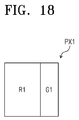
- Each of the first and second pixels PX1 and PX2 has an aspect ratio of 1:1, i.e., a ratio of a length T1 along the first direction DR1 to a length T2 along the second direction DR2.
- Each of the sub-pixels R, G, B, and W has an aspect ratio of 1:1.5, i.e., a ratio of a length T7 along the first direction DR1 to the length T2 along the second direction DR2.
- the sub-pixels arranged in two rows by three columns may have a substantially square shape. That is, the sub-pixels included in the first and third pixel groups PG1 and PG3 may collectively have a square shape.
- each of the first to fourth pixel groups PG1 to PG4 has an aspect ratio of 2:1.
- the first pixel group PG1 includes n (n is an odd number equal to or larger than 3) sub-pixels R, G, and B.
- Each of the sub-pixels R, G, and B included in the first pixel group PG1 has an aspect ratio of 2:n. Since the "n" is 3 in the exemplary embodiment shown in FIG. 17 , the aspect ratio of each of the sub-pixels R, G, and B is 1:1.5.
- the number of data lines in the display apparatus may be reduced to 1/2 even though the display apparatus displays the same resolution as that of the RGB stripe structure.
- the number of data lines in the display apparatus may be reduced by 3/4 even though the display apparatus displays the same resolution as that of the structure in which one pixel includes two RGBW sub-pixels.
- the circuit configuration of the data driver 400 (refer to FIG. 1 ) becomes simpler, and thus a manufacturing cost of the data driver 400 is reduced.
- the aperture ratio of the display apparatus is increased since the number of data lines is reduced.
- FIG. 18 is a view showing a first pixel disposed in a fifth pixel area shown in FIG. 7
- FIGS. 19A and 19B are views showing a re-sample filter used to generate a first pixel data shown in FIG. 18 .
- FIG. 18 shows a first pixel PX1 configured to include a red sub-pixel R1 and a portion of a green sub-pixel G1 as a representative example.
- the red sub-pixel R1 may be referred to as a first normal sub-pixel and the green sub-pixel G1 may be referred to as a first shared sub-pixel.
- the red sub-pixel R1 (first normal sub-pixel) is included in the first pixel PX1 as an independent sub-pixel.
- the green sub-pixel G1 (first shared sub-pixel) corresponds to a portion of the shared sub-pixel.
- the green sub-pixel G1 does not serve as an independent sub-pixel and is to process the data of the portion of the shared sub-pixel included in the first pixel PX1. That is, the green sub-pixel G1 of the first pixel PX1 forms one independent shared sub-pixel together with a green sub-pixel G2 included in the adjacent second pixel PX2.
- the intermediate rendering data RGBW1 which corresponds to the first pixel PX1 is referred to as a first pixel data.
- the first pixel data is configured to include a first normal sub-pixel data corresponding to the first normal sub-pixel R1 and a first shared sub-pixel data corresponding to the first shared sub-pixel G1.
- the first pixel data is generated on the basis of that portion of the RGBW data RGBW which corresponds to the fifth pixel area PA5 in which the first pixel PX1 is disposed, as well as the pixel areas PA1 to PA4 and PA6 to PA9 surrounding the fifth pixel area PA5.
- the first to ninth pixel areas PA1 to PA9 are disposed at positions respectively defined by a first row and a first column, a second row and the first column, a third row and the first column, the first row and a second column, the second row and the second column, the third row and the second column, the first row and a third column, the second row and the third column, and the third row and the third column.
- the first pixel data may be generated on the basis of the data corresponding to the first to ninth pixel areas PA1 to PA9, but the number of the pixel areas should not be limited thereto or thereby.
- the first pixel data may instead be generated on the basis of the data corresponding to ten or more pixel areas.
- the re-sample filter includes a first normal re-sample filter RF11 (refer to FIG. 19A ) and a first shared re-sample filter GF11 (refer to FIG. 19B ).
- the scale coefficient of the re-sample filter indicates a proportion of the RGBW data RGBW corresponding to each pixel area.
- the scale coefficient of the re-sample filter is equal to or greater than zero (0) and smaller than one (1).
- FIG. 19A shows the first normal re-sample filter RF11 used to generate the first normal sub-pixel data of the first pixel data.
- the scale coefficients of the first normal re-sample filter RF11 in the first to ninth pixel areas PA1 to PA9 are 0.0625, 0.125, 0.0625, 0.125, 0.375, 0.125, 0, 0.125, and 0, respectively.
- the first rendering part 2151 multiplies the red data of the RGBW data RGBW which corresponds to the first to ninth pixel areas PA1 to PA9, by the scale coefficients in corresponding positions of the first normal re-sample filter RF11. For instance, the red data corresponding to the first pixel area PA1 is multiplied by the scale coefficient, e.g., 0.0625, of the first normal re-sample filter RF11 corresponding to the first pixel area PA1. Likewise, the red data corresponding to the second pixel area PA2 is multiplied by the scale coefficient, e.g., 0.125, of the first normal re-sample filter RF11 corresponding to the second pixel area PA2. Similarly, the red data corresponding to the ninth pixel area PA9 is multiplied by the scale coefficient, e.g., 0, of the first normal re-sample filter RF11 corresponding to the ninth pixel area PA9.
- the first rendering part 2151 calculates a sum of the values obtained by multiplying the red data of the first to ninth pixel areas PA1 to PA9 by the scale coefficients of the first normal re-sample filter RF1, to produce the first normal sub-pixel data for the first normal sub-pixel R1 of the first pixel PX1.
- FIG. 19B shows the first shared re-sample filter GF11 used to generate the first shared sub-pixel data of the first pixel data.
- the scale coefficients of the first shared re-sample filter GF11 in the first to ninth pixel areas PA1 to PA9 are 0, 15/256, 0, 15/256, 47/256, 15/256, 15/256, 6/256, and 15/256, respectively.
- the first rendering part 2151 multiplies the green data of the RGBW data RGBW which corresponds to the first to ninth pixel areas PA1 to PA9, by the scale coefficients in corresponding positions of the first shared re-sample filter GF11 and calculates a sum of the multiplied values as the first shared sub-pixel data for the first shared sub-pixel G1.
- the rendering operation that calculates the first shared sub-pixel data is substantially similar to that for the first normal sub-pixel data, and thus details thereof will be omitted.
- FIG. 20 is a view showing a second pixel disposed in an eighth pixel area shown in FIG. 7
- FIGS. 21A and 21B are views showing a re-sample filter used to generate a second pixel data for the pixel shown in FIG. 20 .
- FIG. 20 shows a second pixel PX2 configured to include green sub-pixel G2 and a blue sub-pixel B1 as a representative example.
- the blue sub-pixel B2 may be referred to as a second normal sub-pixel and the green sub-pixel G2 may be referred to as a second shared sub-pixel.
- the blue sub-pixel B2 (second normal sub-pixel) is included in the second pixel PX2 as an independent sub-pixel.
- the green sub-pixel G2 (second shared sub-pixel) corresponds to a remaining portion of the shared sub-pixel that includes the green sub-pixel G1 of the first pixel PX1.
- the green sub-pixel G2 of the second pixel PX2 forms the independent shared sub-pixel together with the green sub-pixel G1 included in the first pixel PX1.
- the second pixel data is configured to include a second normal sub-pixel data corresponding to the second normal sub-pixel B2 and a first shared sub-pixel data corresponding to the second shared sub-pixel G2.
- the second pixel data is generated on the basis of that RGBW data which corresponds to the eighth pixel area PA8 in which the second pixel PX2 is disposed, as well as the pixel areas PA4 to PA7 and PA9 to PA12 surrounding the eighth pixel area PA5.
- the fourth to twelfth pixel areas PA4 to PA12 are disposed at positions respectively defined by a first row and a first column, a second row and the first column, a third row and the first column, the first row and a second column, the second row and the second column, the third row and the second column, the first row and a third column, the second row and the third column, and the third row and the third column.
- the second pixel data may be generated on the basis of the data corresponding to the fourth to twelfth pixel areas PA4 to PA12, but the number of pixel areas used should not be limited thereto or thereby.
- the first pixel data may be generated on the basis of the data corresponding to ten or more pixel areas.
- the re-sample filter includes a second shared re-sample filter GF22 (refer to FIG. 21A ) and a second normal re-sample filter BF22 (refer to FIG. 21B ).
- the scale coefficient of the re-sample filter indicates a proportion of the RGBW data RGBW corresponding to each pixel area.
- the scale coefficient of the re-sample filter is equal to or greater than zero (0) and smaller than one (1).
- FIG. 21A shows the second shared re-sample filter GF22 used to generate the second shared sub-pixel data of the second pixel data.
- the scale coefficients of the second shared re-sample filter GF22 in the fourth to twelfth pixel areas PA4 to PA12 are 15/256, 6/256, 15/256, 15/256, 47/256, 15/256, 0, 15/256, and 0, respectively.
- the first rendering part 2151 multiplies the blue data of the RGBW data which corresponds to the fourth to twelfth pixel areas PA4 to PA12, by the scale coefficients in corresponding positions of the second shared re-sample filter GF22. It then calculates a sum of the multiplied values as the second shared sub-pixel data for the second shared sub-pixel G2.
- the rendering operation that calculates the second shared sub-pixel data is substantially similar to that for the first shared sub-pixel data, and thus details thereof will be omitted.
- FIG. 21B shows the second normal re-sample filter BF22 used to generate the second normal sub-pixel data of the second pixel data.
- the scale coefficients of the second normal re-sample filter BF22 in the fourth to twelfth pixel areas PA4 to PA12 are 0, 0.125, 0, 0.125, 0.375, 0.125, 0.0625, 0.125, and 0.0625, respectively.
- the first rendering part 2151 multiplies the blue data of the RGBW data which corresponds to the fourth to twelfth pixel areas PA4 to PA12, by the scale coefficients in corresponding positions of the second normal re-sample filter BF22. It then calculates a sum of the multiplied values as the second normal sub-pixel data for the second normal sub-pixel B2.
- the rendering operation that calculates the second normal sub-pixel data is substantially similar to that of the first normal sub-pixel data, and thus details thereof will be omitted.
- the scale coefficients of the re-sample filter are determined by taking the area of the corresponding sub-pixel in each pixel into consideration.
- the first and second pixels PX1 and PX2 will be described as a representative example.
- the area of the first normal sub-pixel R1 is greater than that of the first shared sub-pixel G1. More specifically, the area of the first normal sub-pixel R1 is two times greater than that of the first shared sub-pixel G1.
- a sum of the scale coefficients of the first shared re-sample filter GF11 may be half of that of the scale coefficients of the first normal re-sample filter RF11. Referring to FIGS. 19A and 19B , the sum of the scale coefficients of the first normal re-sample filter RF11 becomes 1 and the sum of the scale coefficients of the first shared re-sample filter GF11 becomes 0.5.
- the maximum grayscale of the first shared sub-pixel data corresponds to one half of the maximum grayscale of each of the first and second normal sub-pixel data.
- the area of the second normal sub-pixel B2 is greater than that of the second shared sub-pixel G2.
- the area of the second normal sub-pixel B2 is two times greater than that of the second shared sub-pixel G2.
- a sum of the scale coefficients of the second shared re-sample filter GF22 may thus be one half of that of the scale coefficients of the second normal re-sample filter BF22. Referring to FIGS. 21A and 21B , the sum of the scale coefficients of the second normal re-sample filter BF22 becomes 1 and the sum of the scale coefficients of the second shared re-sample filter GF22 becomes 0.5.
- the maximum grayscale of the second shared sub-pixel data corresponds to a half of the maximum grayscale of the second normal sub-pixel data.
- the second rendering part 2153 calculates the first and second shared sub-pixel data of the intermediate rendering data RGBW1 to generate a shared sub-pixel data.
- the second rendering part 2153 may generate the shared sub-pixel data by adding the first shared sub-pixel data of the first pixel data and the second shared sub-pixel data of the second pixel data.
- FIG. 22 is a graph showing a transmittance as a function of a pixel density (hereinafter, referred to as a pixel per inch (ppi)), for a display apparatus including the display panel shown in FIG. 17 , a first comparison example, and a second comparison example.
- ppi pixel per inch
- Table 2 shows the transmittance as a function of ppi, for a display apparatus including the display panel shown in FIG. 17 , the first comparison example, and the second comparison example.
- the first comparison example indicates a structure in which one pixel is configured to include two RGBW sub-pixels along the first direction DR1
- the second comparison example indicates an RGB stripe structure in which one pixel is configured to include three sub-pixels along the first direction DR1.
- a maximum ppi of the embodiment example, the first comparison example, and the second comparison example indicates a value measured when a process threshold value for a short side (a length along the first direction DR1 of each sub-pixel in the display panel shown in FIG. 2 ) of each sub-pixel is set to about 15 micrometers.
- the display apparatus including the display panel shown in FIG. 17 has a maximum ppi higher than that of the first and second comparison examples under the same conditions.
- the display apparatus according to the present disclosure has a maximum ppi of about 1128
- the first comparison example has a maximum ppi of about 834
- the second comparison example has a maximum ppi of about 564.
- the display apparatus of the embodiment example has a transmittance higher than that of the first and second comparison examples.
- the display apparatus of the embodiment example has a transmittance of about 7.9%
- the first comparison example has a transmittance of about 7.5%
- the second comparison example has a transmittance of about 3.98%.
- FIG. 23 is a view showing a portion of a display panel 106 according to another exemplary embodiment of the present disclosure.
- the display panel 106 shown in FIG. 23 has substantially the same structure and function as those of the display panel 105 shown in FIG. 17 , except for the difference in color arrangement of the sub-pixels.
- features of the display panel 106 that differ from those of the display panel 105 will mainly be described.
- the sub-pixels R, G, B, and W are repeatedly arranged in units of sub-pixel group SPG, which is configured to include twelve sub-pixels arranged in two rows by six columns.
- the sub-pixel group SPG includes four red sub-pixels, four green sub-pixels, two blue-sub pixels, and two white sub-pixels.
- the sub-pixels arranged in the first row of the sub-pixel group SPG are arranged in order of a red sub-pixel R, a blue sub-pixel B, a green sub-pixel G, a red sub-pixel R, a white sub-pixel W, and a blue sub-pixel B along the first direction DR1.
- the sub-pixels arranged in the second row of the sub-pixel group SPG are arranged in order of a green sub-pixel G, a white sub-pixel W, a red sub-pixel R, a green sub-pixel G, a blue sub-pixel B, and a red sub-pixel R along the first direction DR1.
- the arrangement order of the sub-pixels should not be limited to the above-mentioned orders. As with every embodiment disclosed herein, any order of sub-pixels is contemplated.
- FIG. 24 is a view showing a portion of a display panel 107 according to another exemplary embodiment of the present disclosure.
- the display panel 107 shown in FIG. 24 has substantially the same structure and function as those of the display panel 105 shown in FIG. 17 , except for the difference in color arrangement of the sub-pixels.
- features of the display panel 107 that differ from those of the display panel 105 will mainly be described.
- the display panel 107 includes a plurality of sub-pixels R, G, and B.
- the sub-pixels R, G, and B are repeatedly arranged in units of sub-pixel group SPG, which is configured to include three sub-pixels arranged in one row by three columns.
- the sub-pixel group SPG includes one red sub-pixel, one green sub-pixel, and one blue-sub pixel. That is, the display panel 107 shown in FIG. 24 does not include a white sub-pixel W when compared with the display panel 105 shown in FIG. 17 .
- the sub-pixels R, G, and B are arranged in units of three sub-pixels adjacent to each other along the first direction DR1.
- the three sub-pixels are arranged along the first direction DR1 in order of a red sub-pixel R, a green sub-pixel G, and a blue sub-pixel B.
- the arrangement order of the sub-pixels should not be limited to that shown. Any order is contemplated
- the display panel 107 includes pixel groups PG1 and PG2.
- Each of the pixel groups PG1 and PG2 of the display panel 107 shown in FIG. 24 has substantially the same structure and function as those of the pixel groups PG1 to PG4 shown in FIG. 17 , except for the difference in color arrangement of the sub-pixels, and thus detailed descriptions of the pixel groups PG1 and PG2 will be omitted.
- FIG. 25 is a view showing a portion of a display panel 108 according to another exemplary embodiment of the present disclosure.
- the display panel 108 shown in FIG. 25 has substantially the same structure and function as those of the display panel 107 shown in FIG. 24 , except for the difference in color arrangement of the sub-pixels.
- features of the display panel 108 that differ from those of the display panel 107 will mainly be described.
- the sub-pixels are repeatedly arranged in the unit of sub-pixel group SPG, which is configured to include three sub-pixels R11, G11, and B11 arranged in a first row and three sub-pixels B22, R22, and G22 arranged in a second row.
- the sub-pixels R11, G11, and B11 disposed in the first row are arranged in order of a red sub-pixel R11, a green sub-pixel G11, and a blue sub-pixel B11 along the first direction DR1.
- the sub-pixels B22, R22, and G22 disposed in the first row are arranged in order of a blue sub-pixel B22, a red sub-pixel R22, and a green sub-pixel G22 along the first direction DR1.
- the sub-pixels B22, R22, and G22 arranged in the second row are shifted or offset in the first direction DR1 by a first distance P corresponding to a half of a width 2P of a sub-pixel.
- the blue sub-pixel B22 arranged in the second row is shifted in the first direction DR1 by the first distance P with respect to the red sub-pixel R11 arranged in the first row
- the red sub-pixel R22 arranged in the second row is shifted in the first direction DR1 by the first distance P with respect to the green sub-pixel G11 arranged in the first row
- the green sub-pixel G22 arranged in the second row is shifted in the first direction DR1 by the first distance P with respect to the blue sub-pixel B11 arranged in the first row.
- the display panel 108 includes pixel groups PG1 and PG2.
- Each of the pixel groups PG1 and PG2 of the display panel 108 shown in FIG. 25 has the same structure and function as those of the pixel groups PG1 to PG4 shown in FIG. 17 , except for the difference in color arrangement of the sub-pixels, and thus detailed descriptions of the pixel groups PG1 and PG2 will be omitted.
- the display panel 108 shown in FIG. 25 a distance between the sub-pixels having the same color and being disposed adjacent to each other is uniform compared with the display panel 107 shown in FIG. 24 . Accordingly, the display panel 108 shown in FIG. 25 may display images in more detail than the display panel 107 shown in FIG. 24 , which has substantially the same resolution as that of the display panel 108 shown in FIG. 25 .
- FIG. 26 is a view showing a portion of a display panel 109 according to another exemplary embodiment of the present disclosure.
- the long side of the sub-pixel of the display panel 109 shown in FIG. 26 extends along the first direction DR1 and two pixels adjacent to each other along the second direction DR2 share a shared sub-pixel.
- features of the display panel 109 that differ from the display panel 105 will be described in further detail.
- sub-pixels R, G, B, and W are repeatedly arranged in units of sub-pixel group SPG, which is configured to include eight sub-pixels arranged in four rows by two columns.
- the sub-pixel group SPG includes two red sub-pixels R, two green sub-pixels G, two blue-sub pixels B, and two white sub-pixels W.
- the sub-pixels arranged in the first column of the sub-pixel group SPG are arranged in order of a red sub-pixel R, a green sub-pixel G, a blue sub-pixel B, and a white sub-pixel W along the second direction DR2.
- the sub-pixels arranged in the second column of the sub-pixel group SPG are arranged in order of a blue sub-pixel B, a white sub-pixel W, a red sub-pixel R, and a green sub-pixel G along the second direction DR2.
- the arrangement order of the colors of the sub-pixels should not be limited to the above-mentioned orders.
- the display panel 109 includes pixel groups PG1 to PG4, each including two pixels adjacent to each other.
- the pixel groups PG1 to PG4 have the same structure except for the difference in color arrangement of the sub-pixels thereof, and thus hereinafter, only the first pixel group PG1 will be described in detail.
- the first pixel group PG1 includes a first pixel PX1 and a second pixel PX2, which are disposed adjacent to each other along the second direction DR2.
- the first and second pixels PX1 and PX2 share a shared sub-pixel G.
- each of the first and second pixels PX1 and PX2 includes one and a half sub-pixels.
- the first pixel PX1 includes a red sub-pixel R and half of a green sub-pixel G, which are arranged along the second direction DR2.
- the second pixel PX2 includes a remaining half of the green sub-pixel G and a blue sub-pixel B, which are arranged along the second direction DR2.
- the number of sub-pixels may be one and a half times greater than the number of pixels.
- the first and second pixels PX1 and PX2 are configured to include three sub-pixels R, G, and B.
- the aspect ratio i.e., a ratio of a length T1 along the first direction DR1 to a length T2 along the second direction DR2, of each of the first and second pixels PX1 and PX2 is substantially 1:1.
- the aspect ratio i.e., a ratio of the length along the first direction DR1 to the length along the second direction DR2, of each of the first to fourth pixel groups PG1 to PG4 is substantially 1:2.
- the aspect ratio i.e., a ratio of the length T1 along the first direction DR1 to the length T8 along the second direction DR2, is substantially 1.5:1.
- the long side of the sub-pixels extends along the first direction DR1, and thus the number of data lines in the display panel 109 may be reduced compared with the number of data lines in the display panel 105 shown in FIG. 17 . Therefore, the number of driver ICs may be reduced and the manufacturing cost of the display panel may be reduced.
- the arrangement of the sub-pixels of the display panel 109 shown in FIG. 26 is similar to the arrangement of the sub-pixels of the display panel 105 shown in FIG. 17 when the display panel 105 shown in FIG. 17 is rotated in a counter-clockwise direction at an angle of about 90 degrees and then mirrored about axis DR1.
- the sub-pixels according to another exemplary embodiment may be repeatedly arranged in units of the sub-pixel groups shown in FIGS. 23 and 24 , when rotated in a clockwise or counter clockwise direction at an angle of about 90 degrees and then mirrored about axis DR1.
Landscapes
- Engineering & Computer Science (AREA)
- Physics & Mathematics (AREA)
- Computer Hardware Design (AREA)
- General Physics & Mathematics (AREA)
- Theoretical Computer Science (AREA)
- Control Of Indicators Other Than Cathode Ray Tubes (AREA)
- Liquid Crystal Display Device Control (AREA)
- Liquid Crystal (AREA)
- Transforming Electric Information Into Light Information (AREA)
- Electroluminescent Light Sources (AREA)
- Devices For Indicating Variable Information By Combining Individual Elements (AREA)
Applications Claiming Priority (1)
| Application Number | Priority Date | Filing Date | Title |
|---|---|---|---|
| KR1020140098227A KR101934088B1 (ko) | 2014-07-31 | 2014-07-31 | 표시 장치 및 그 구동 방법 |
Publications (2)
| Publication Number | Publication Date |
|---|---|
| EP2980780A2 true EP2980780A2 (de) | 2016-02-03 |
| EP2980780A3 EP2980780A3 (de) | 2016-02-17 |
Family
ID=53785441
Family Applications (1)
| Application Number | Title | Priority Date | Filing Date |
|---|---|---|---|
| EP15177188.8A Ceased EP2980780A3 (de) | 2014-07-31 | 2015-07-17 | Anzeigevorrichtung und deren ansteuerverfahren |
Country Status (6)
| Country | Link |
|---|---|
| US (2) | US9728116B2 (de) |
| EP (1) | EP2980780A3 (de) |
| JP (2) | JP2016035561A (de) |
| KR (1) | KR101934088B1 (de) |
| CN (1) | CN105321448B (de) |
| TW (1) | TWI614739B (de) |
Cited By (3)
| Publication number | Priority date | Publication date | Assignee | Title |
|---|---|---|---|---|
| EP3273440A1 (de) * | 2016-07-22 | 2018-01-24 | LG Electronics Inc. | Bildanzeigevorrichtung |
| CN110574097A (zh) * | 2016-11-28 | 2019-12-13 | 上海云英谷科技有限公司 | 液晶显示器(lcd)面板的分布式驱动 |
| KR20200137031A (ko) * | 2018-04-26 | 2020-12-08 | 어플라이드 머티어리얼스, 인코포레이티드 | 고체 상태 방출기 어레이들을 사용하는 시스템들 및 방법들 |
Families Citing this family (25)
| Publication number | Priority date | Publication date | Assignee | Title |
|---|---|---|---|---|
| CN103854570B (zh) * | 2014-02-20 | 2016-08-17 | 北京京东方光电科技有限公司 | 显示基板及其驱动方法和显示装置 |
| KR20160011293A (ko) * | 2014-07-21 | 2016-02-01 | 삼성디스플레이 주식회사 | 표시 장치 |
| KR20160097444A (ko) * | 2015-02-06 | 2016-08-18 | 삼성디스플레이 주식회사 | 표시 장치 |
| CN104597609A (zh) * | 2015-02-06 | 2015-05-06 | 京东方科技集团股份有限公司 | 像素阵列、显示装置以及显示方法 |
| CN105489177B (zh) * | 2015-11-30 | 2018-06-29 | 信利(惠州)智能显示有限公司 | 子像素渲染方法及渲染装置 |
| US9846340B1 (en) * | 2016-06-15 | 2017-12-19 | A.U. Vista, Inc. | Pixel structure utilizing photo spacer stage design and display device having the same |
| KR102543039B1 (ko) * | 2016-07-29 | 2023-06-15 | 엘지디스플레이 주식회사 | 유기발광 표시장치와 그의 암점 처리방법 |
| CN107845358B (zh) * | 2016-09-20 | 2021-04-27 | 联咏科技股份有限公司 | 显示器驱动设备和显示器驱动方法 |
| KR102544322B1 (ko) * | 2016-09-26 | 2023-06-19 | 삼성디스플레이 주식회사 | 발광 표시 장치 |
| CN106856084B (zh) * | 2016-12-23 | 2020-12-04 | 上海天马有机发光显示技术有限公司 | 一种显示面板的显示方法及显示装置 |
| KR102392373B1 (ko) * | 2017-08-24 | 2022-04-29 | 삼성디스플레이 주식회사 | 표시 장치 |
| CN207320118U (zh) * | 2017-08-31 | 2018-05-04 | 昆山国显光电有限公司 | 像素结构、掩膜版及显示装置 |
| KR102477570B1 (ko) * | 2017-12-27 | 2022-12-14 | 삼성디스플레이 주식회사 | 표시 장치 |
| US11152551B2 (en) * | 2018-04-27 | 2021-10-19 | Innolux Corporation | Electronic device |
| US10488762B1 (en) * | 2018-06-29 | 2019-11-26 | Applied Materials, Inc. | Method to reduce data stream for spatial light modulator |
| CN109559650B (zh) | 2019-01-16 | 2021-01-12 | 京东方科技集团股份有限公司 | 一种像素渲染方法及装置、图像渲染方法及装置、显示装置 |
| CN109599075B (zh) * | 2019-01-30 | 2020-12-15 | 惠科股份有限公司 | 显示面板的驱动方法、驱动装置、及显示设备 |
| KR102718330B1 (ko) | 2019-05-13 | 2024-10-18 | 삼성디스플레이 주식회사 | 표시 장치 및 표시 장치의 구동 방법 |
| US11190755B2 (en) * | 2019-06-12 | 2021-11-30 | Sony Interactive Entertainment Inc. | Asymmetric arrangement of left and right displays to improve image quality for a stereoscopic head-mounted display (HMD) |
| KR102827898B1 (ko) * | 2019-07-23 | 2025-07-02 | 삼성전자주식회사 | 이미지 데이터의 레이어를 블렌딩하기 위한 전자 장치 |
| CN115019676B (zh) * | 2019-10-30 | 2023-05-02 | 武汉天马微电子有限公司 | 一种显示面板的渲染方法、显示面板和显示装置 |
| KR102314074B1 (ko) * | 2019-10-31 | 2021-10-19 | 칩원 테크놀로지(베이징) 컴퍼니 리미티드 | 부화소 렌더링 방법, 구동 칩 및 표시 장치 |
| KR102928445B1 (ko) | 2020-10-12 | 2026-02-19 | 삼성디스플레이 주식회사 | 표시 장치 |
| US12302729B2 (en) * | 2021-07-27 | 2025-05-13 | Beijing Boe Optoelectronics Technology Co., Ltd. | Display panel including display regions with different pixel densities, display device including the display panel and display driving method of the display panel |
| CN120615339A (zh) * | 2023-02-02 | 2025-09-09 | 维耶尔公司 | 高分辨率显示器 |
Family Cites Families (44)
| Publication number | Priority date | Publication date | Assignee | Title |
|---|---|---|---|---|
| JPS5321627B2 (de) | 1972-12-29 | 1978-07-04 | ||
| US5341153A (en) * | 1988-06-13 | 1994-08-23 | International Business Machines Corporation | Method of and apparatus for displaying a multicolor image |
| DE19746329A1 (de) | 1997-09-13 | 1999-03-18 | Gia Chuong Dipl Ing Phan | Display und Verfahren zur Ansteuerung des Displays |
| US7105795B2 (en) * | 2001-07-06 | 2006-09-12 | Palantyr Research, Llc | Imaging system, methodology, and applications employing reciprocal space optical design |
| JP3870807B2 (ja) | 2001-12-20 | 2007-01-24 | ソニー株式会社 | 画像表示装置及びその製造方法 |
| US7583279B2 (en) | 2004-04-09 | 2009-09-01 | Samsung Electronics Co., Ltd. | Subpixel layouts and arrangements for high brightness displays |
| US7417648B2 (en) | 2002-01-07 | 2008-08-26 | Samsung Electronics Co. Ltd., | Color flat panel display sub-pixel arrangements and layouts for sub-pixel rendering with split blue sub-pixels |
| US20040051724A1 (en) | 2002-09-13 | 2004-03-18 | Elliott Candice Hellen Brown | Four color arrangements of emitters for subpixel rendering |
| JP3839332B2 (ja) * | 2002-03-01 | 2006-11-01 | 三菱電機株式会社 | 表示装置 |
| KR100825106B1 (ko) | 2002-05-03 | 2008-04-25 | 삼성전자주식회사 | 액정 표시 장치 |
| EP1388818B1 (de) * | 2002-08-10 | 2011-06-22 | Samsung Electronics Co., Ltd. | Verfahren und Anordnung zur Wiedergabe eines Bildsignals |
| JP2004117431A (ja) * | 2002-09-24 | 2004-04-15 | Sharp Corp | カラー表示装置 |
| US20040080479A1 (en) | 2002-10-22 | 2004-04-29 | Credelle Thomas Lioyd | Sub-pixel arrangements for striped displays and methods and systems for sub-pixel rendering same |
| KR100943273B1 (ko) * | 2003-05-07 | 2010-02-23 | 삼성전자주식회사 | 4-컬러 변환 방법 및 그 장치와 이를 이용한 유기전계발광표시장치 |
| KR100995022B1 (ko) | 2003-12-13 | 2010-11-19 | 엘지디스플레이 주식회사 | 디스플레이 및 그 구동방법 |
| US20060158466A1 (en) | 2005-01-18 | 2006-07-20 | Sitronix Technology Corp. | Shared pixels rendering display |
| KR101256965B1 (ko) * | 2005-06-22 | 2013-04-26 | 엘지디스플레이 주식회사 | 액정표시장치 및 그 구동방법 |
| JP2007088656A (ja) | 2005-09-21 | 2007-04-05 | Sony Corp | ラジオ受信機及びラジオ受信機の制御方法 |
| JP4302172B2 (ja) * | 2006-02-02 | 2009-07-22 | シャープ株式会社 | 表示装置 |
| US20070257945A1 (en) | 2006-05-08 | 2007-11-08 | Eastman Kodak Company | Color EL display system with improved resolution |
| JP5235901B2 (ja) * | 2007-02-13 | 2013-07-10 | 三星ディスプレイ株式會社 | 指向性表示装置用のサブピクセルレイアウト及びサブピクセルレンダリング方法及びシステム |
| KR100892225B1 (ko) | 2007-04-16 | 2009-04-09 | 삼성전자주식회사 | 컬러 디스플레이 장치 |
| JP5256283B2 (ja) | 2007-05-18 | 2013-08-07 | 三星ディスプレイ株式會社 | 2次元サブピクセルレイアウトを有するディスプレイパネルのための画像色バランス調整 |
| JP2008292932A (ja) | 2007-05-28 | 2008-12-04 | Funai Electric Co Ltd | 画像表示装置および液晶テレビジョン |
| KR20090010826A (ko) | 2007-07-24 | 2009-01-30 | 삼성전자주식회사 | 표시장치 및 표시장치의 구동방법 |
| JP5358918B2 (ja) | 2007-09-28 | 2013-12-04 | カシオ計算機株式会社 | 液晶表示素子の駆動方法 |
| KR20090073903A (ko) | 2007-12-31 | 2009-07-03 | 엘지디스플레이 주식회사 | 컬러 epd 장치의 화소배치방법 |
| JP5377057B2 (ja) | 2008-06-30 | 2013-12-25 | 株式会社ジャパンディスプレイ | 画像表示装置の駆動方法、並びに、画像表示装置組立体及びその駆動方法 |
| JP5236422B2 (ja) | 2008-10-16 | 2013-07-17 | シャープ株式会社 | 透過型液晶表示装置 |
| US8390642B2 (en) * | 2009-04-30 | 2013-03-05 | Hewlett-Packard Development Company, L.P. | System and method for color space setting adjustment |
| KR101587606B1 (ko) | 2009-09-07 | 2016-01-25 | 삼성디스플레이 주식회사 | 데이터 처리 장치, 이를 갖는 표시 시스템 및 데이터 처리 방법 |
| KR101588336B1 (ko) | 2009-12-17 | 2016-01-26 | 삼성디스플레이 주식회사 | 데이터 처리 방법 및 이를 수행하기 위한 표시 장치 |
| DE102011053000B4 (de) * | 2010-08-27 | 2017-08-17 | Lg Display Co., Ltd. | Organische elektrolumineszente Vorrichtung |
| KR101782054B1 (ko) * | 2011-02-14 | 2017-09-26 | 엘지디스플레이 주식회사 | 액정 표시장치와 이의 구동방법 |
| JP5321627B2 (ja) | 2011-03-24 | 2013-10-23 | 船井電機株式会社 | 液晶表示装置 |
| US20120262476A1 (en) * | 2011-04-13 | 2012-10-18 | Himax Technologies Limited | Pixel conversion system and method |
| JP2013008887A (ja) | 2011-06-27 | 2013-01-10 | Hitachi Ltd | 光モジュール |
| WO2013008887A1 (ja) * | 2011-07-13 | 2013-01-17 | シャープ株式会社 | 多原色表示装置 |
| KR101992103B1 (ko) | 2011-12-09 | 2019-06-25 | 엘지디스플레이 주식회사 | 액정표시장치 및 그 구동방법 |
| JP6053278B2 (ja) | 2011-12-14 | 2016-12-27 | 三菱電機株式会社 | 2画面表示装置 |
| CN103700329B (zh) | 2013-12-13 | 2015-11-11 | 北京京东方光电科技有限公司 | 显示面板的显示方法 |
| CN103854570B (zh) * | 2014-02-20 | 2016-08-17 | 北京京东方光电科技有限公司 | 显示基板及其驱动方法和显示装置 |
| CN103886825B (zh) * | 2014-02-21 | 2016-02-17 | 北京京东方光电科技有限公司 | 像素阵列的驱动方法和显示装置 |
| CN103886808B (zh) * | 2014-02-21 | 2016-02-24 | 北京京东方光电科技有限公司 | 显示方法和显示装置 |
-
2014
- 2014-07-31 KR KR1020140098227A patent/KR101934088B1/ko active Active
-
2015
- 2015-07-10 US US14/796,579 patent/US9728116B2/en active Active
- 2015-07-16 JP JP2015142336A patent/JP2016035561A/ja active Pending
- 2015-07-16 TW TW104123055A patent/TWI614739B/zh active
- 2015-07-17 EP EP15177188.8A patent/EP2980780A3/de not_active Ceased
- 2015-07-21 CN CN201510430894.2A patent/CN105321448B/zh active Active
-
2017
- 2017-07-07 US US15/644,448 patent/US10157564B2/en active Active
-
2018
- 2018-01-11 JP JP2018002810A patent/JP6887961B2/ja active Active
Non-Patent Citations (1)
| Title |
|---|
| None |
Cited By (8)
| Publication number | Priority date | Publication date | Assignee | Title |
|---|---|---|---|---|
| EP3273440A1 (de) * | 2016-07-22 | 2018-01-24 | LG Electronics Inc. | Bildanzeigevorrichtung |
| CN107872722A (zh) * | 2016-07-22 | 2018-04-03 | Lg电子株式会社 | 图像显示设备 |
| US10593273B2 (en) | 2016-07-22 | 2020-03-17 | Lg Electronics Inc. | Image display apparatus capable of improving sharpness of an edge area |
| CN110574097A (zh) * | 2016-11-28 | 2019-12-13 | 上海云英谷科技有限公司 | 液晶显示器(lcd)面板的分布式驱动 |
| CN110574097B (zh) * | 2016-11-28 | 2022-04-26 | 昆山云英谷电子科技有限公司 | 液晶显示器(lcd)面板的分布式驱动 |
| EP3545515B1 (de) * | 2016-11-28 | 2023-04-19 | Kunshan Yunyinggu Electronic Technology Co., Ltd. | Distributive ansteuerung einer flüssigkristallanzeigetafel (lcd) |
| KR20200137031A (ko) * | 2018-04-26 | 2020-12-08 | 어플라이드 머티어리얼스, 인코포레이티드 | 고체 상태 방출기 어레이들을 사용하는 시스템들 및 방법들 |
| EP3785080A4 (de) * | 2018-04-26 | 2022-01-19 | Applied Materials, Inc. | Systeme und verfahren zur verwendung von festkörper-emitter-arrays |
Also Published As
| Publication number | Publication date |
|---|---|
| US9728116B2 (en) | 2017-08-08 |
| US10157564B2 (en) | 2018-12-18 |
| JP2018101140A (ja) | 2018-06-28 |
| KR20160017683A (ko) | 2016-02-17 |
| JP6887961B2 (ja) | 2021-06-16 |
| EP2980780A3 (de) | 2016-02-17 |
| US20170309214A1 (en) | 2017-10-26 |
| TW201604856A (zh) | 2016-02-01 |
| CN105321448B (zh) | 2019-12-03 |
| JP2016035561A (ja) | 2016-03-17 |
| CN105321448A (zh) | 2016-02-10 |
| KR101934088B1 (ko) | 2019-01-03 |
| US20160035265A1 (en) | 2016-02-04 |
| TWI614739B (zh) | 2018-02-11 |
Similar Documents
| Publication | Publication Date | Title |
|---|---|---|
| EP2980780A2 (de) | Anzeigevorrichtung und deren ansteuerverfahren | |
| KR101587606B1 (ko) | 데이터 처리 장치, 이를 갖는 표시 시스템 및 데이터 처리 방법 | |
| KR101787238B1 (ko) | 표시 장치 | |
| US10140935B2 (en) | Display apparatus driven in an inversion driving manner and method of processing data thereof | |
| US9835908B2 (en) | Display apparatus | |
| CN107393490B (zh) | 显示设备 | |
| US20160247460A1 (en) | Display apparatus and driving method thereof | |
| US9589494B2 (en) | Display device | |
| US10102788B2 (en) | Display device having white pixel and driving method therefor | |
| CN107016969B (zh) | 显示装置及其驱动方法 | |
| US9111480B2 (en) | Liquid crystal display and a method of driving the same by converting three color input image signals based on a hue shift of yellow | |
| US9965990B2 (en) | Display apparatus having improved sub-pixel rendering capability | |
| KR20160047653A (ko) | 표시 장치 | |
| CN105869557A (zh) | 显示装置 | |
| CN104778929B (zh) | 一种显示面板的驱动数据的转换方法及转换系统 | |
| KR102520697B1 (ko) | 서브픽셀 렌더링 디스플레이 장치 및 그의 영상 처리 방법 | |
| US20130021334A1 (en) | Liquid crystal display | |
| US20130082913A1 (en) | Voltage selection apparatus and voltage selection method | |
| US20210287630A1 (en) | Display apparatus and method of driving the same | |
| US10089942B2 (en) | Display device and driving method thereof | |
| US9052089B2 (en) | Display panel having a pixel arrangement that provides a broad color gamut, and display apparatus having the same | |
| US12614492B2 (en) | Display apparatus and method of driving display panel using the same |
Legal Events
| Date | Code | Title | Description |
|---|---|---|---|
| PUAL | Search report despatched |
Free format text: ORIGINAL CODE: 0009013 |
|
| PUAI | Public reference made under article 153(3) epc to a published international application that has entered the european phase |
Free format text: ORIGINAL CODE: 0009012 |
|
| AK | Designated contracting states |
Kind code of ref document: A2 Designated state(s): AL AT BE BG CH CY CZ DE DK EE ES FI FR GB GR HR HU IE IS IT LI LT LU LV MC MK MT NL NO PL PT RO RS SE SI SK SM TR |
|
| AX | Request for extension of the european patent |
Extension state: BA ME |
|
| AK | Designated contracting states |
Kind code of ref document: A3 Designated state(s): AL AT BE BG CH CY CZ DE DK EE ES FI FR GB GR HR HU IE IS IT LI LT LU LV MC MK MT NL NO PL PT RO RS SE SI SK SM TR |
|
| AX | Request for extension of the european patent |
Extension state: BA ME |
|
| RIC1 | Information provided on ipc code assigned before grant |
Ipc: G09G 3/20 20060101AFI20160108BHEP |
|
| 17P | Request for examination filed |
Effective date: 20160509 |
|
| RBV | Designated contracting states (corrected) |
Designated state(s): AL AT BE BG CH CY CZ DE DK EE ES FI FR GB GR HR HU IE IS IT LI LT LU LV MC MK MT NL NO PL PT RO RS SE SI SK SM TR |
|
| 17Q | First examination report despatched |
Effective date: 20160616 |
|
| STAA | Information on the status of an ep patent application or granted ep patent |
Free format text: STATUS: THE APPLICATION HAS BEEN REFUSED |
|
| 18R | Application refused |
Effective date: 20171219 |