EP2980934A1 - Glasfaser und laseroszillator damit - Google Patents
Glasfaser und laseroszillator damit Download PDFInfo
- Publication number
- EP2980934A1 EP2980934A1 EP14775306.5A EP14775306A EP2980934A1 EP 2980934 A1 EP2980934 A1 EP 2980934A1 EP 14775306 A EP14775306 A EP 14775306A EP 2980934 A1 EP2980934 A1 EP 2980934A1
- Authority
- EP
- European Patent Office
- Prior art keywords
- optical fiber
- core
- fiber body
- light
- end surface
- Prior art date
- Legal status (The legal status is an assumption and is not a legal conclusion. Google has not performed a legal analysis and makes no representation as to the accuracy of the status listed.)
- Granted
Links
- 239000013307 optical fiber Substances 0.000 title claims abstract description 182
- 238000005253 cladding Methods 0.000 claims abstract description 20
- 230000035699 permeability Effects 0.000 claims abstract description 7
- 230000005284 excitation Effects 0.000 claims description 34
- 238000001816 cooling Methods 0.000 claims description 13
- 239000005371 ZBLAN Substances 0.000 claims description 8
- 229910052691 Erbium Inorganic materials 0.000 claims description 7
- UYAHIZSMUZPPFV-UHFFFAOYSA-N erbium Chemical group [Er] UYAHIZSMUZPPFV-UHFFFAOYSA-N 0.000 claims description 7
- 239000005383 fluoride glass Substances 0.000 claims description 7
- 239000011521 glass Substances 0.000 claims description 7
- 229910052761 rare earth metal Inorganic materials 0.000 claims description 4
- WUKWITHWXAAZEY-UHFFFAOYSA-L calcium difluoride Chemical compound [F-].[F-].[Ca+2] WUKWITHWXAAZEY-UHFFFAOYSA-L 0.000 claims description 3
- 229910001634 calcium fluoride Inorganic materials 0.000 claims description 3
- 238000010276 construction Methods 0.000 description 16
- 239000000835 fiber Substances 0.000 description 6
- 230000004048 modification Effects 0.000 description 5
- 238000012986 modification Methods 0.000 description 5
- 230000005540 biological transmission Effects 0.000 description 4
- 239000003507 refrigerant Substances 0.000 description 4
- 230000004927 fusion Effects 0.000 description 3
- IJGRMHOSHXDMSA-UHFFFAOYSA-N Atomic nitrogen Chemical compound N#N IJGRMHOSHXDMSA-UHFFFAOYSA-N 0.000 description 2
- 238000010521 absorption reaction Methods 0.000 description 2
- 230000004308 accommodation Effects 0.000 description 2
- 239000013078 crystal Substances 0.000 description 2
- 238000010586 diagram Methods 0.000 description 2
- 230000020169 heat generation Effects 0.000 description 2
- RYGMFSIKBFXOCR-UHFFFAOYSA-N Copper Chemical compound [Cu] RYGMFSIKBFXOCR-UHFFFAOYSA-N 0.000 description 1
- 238000002835 absorbance Methods 0.000 description 1
- 229910052802 copper Inorganic materials 0.000 description 1
- 239000010949 copper Substances 0.000 description 1
- 239000002274 desiccant Substances 0.000 description 1
- 230000000694 effects Effects 0.000 description 1
- 238000004020 luminiscence type Methods 0.000 description 1
- 238000002844 melting Methods 0.000 description 1
- 230000008018 melting Effects 0.000 description 1
- 229910052757 nitrogen Inorganic materials 0.000 description 1
- 239000010453 quartz Substances 0.000 description 1
- 239000004065 semiconductor Substances 0.000 description 1
- VYPSYNLAJGMNEJ-UHFFFAOYSA-N silicon dioxide Inorganic materials O=[Si]=O VYPSYNLAJGMNEJ-UHFFFAOYSA-N 0.000 description 1
Images


Classifications
-
- H—ELECTRICITY
- H01—ELECTRIC ELEMENTS
- H01S—DEVICES USING THE PROCESS OF LIGHT AMPLIFICATION BY STIMULATED EMISSION OF RADIATION [LASER] TO AMPLIFY OR GENERATE LIGHT; DEVICES USING STIMULATED EMISSION OF ELECTROMAGNETIC RADIATION IN WAVE RANGES OTHER THAN OPTICAL
- H01S3/00—Lasers, i.e. devices using stimulated emission of electromagnetic radiation in the infrared, visible or ultraviolet wave range
- H01S3/02—Constructional details
- H01S3/04—Arrangements for thermal management
- H01S3/042—Arrangements for thermal management for solid state lasers
-
- H—ELECTRICITY
- H01—ELECTRIC ELEMENTS
- H01S—DEVICES USING THE PROCESS OF LIGHT AMPLIFICATION BY STIMULATED EMISSION OF RADIATION [LASER] TO AMPLIFY OR GENERATE LIGHT; DEVICES USING STIMULATED EMISSION OF ELECTROMAGNETIC RADIATION IN WAVE RANGES OTHER THAN OPTICAL
- H01S3/00—Lasers, i.e. devices using stimulated emission of electromagnetic radiation in the infrared, visible or ultraviolet wave range
- H01S3/05—Construction or shape of optical resonators; Accommodation of active medium therein; Shape of active medium
- H01S3/06—Construction or shape of active medium
- H01S3/063—Waveguide lasers, i.e. whereby the dimensions of the waveguide are of the order of the light wavelength
- H01S3/067—Fibre lasers
- H01S3/06704—Housings; Packages
-
- H—ELECTRICITY
- H01—ELECTRIC ELEMENTS
- H01S—DEVICES USING THE PROCESS OF LIGHT AMPLIFICATION BY STIMULATED EMISSION OF RADIATION [LASER] TO AMPLIFY OR GENERATE LIGHT; DEVICES USING STIMULATED EMISSION OF ELECTROMAGNETIC RADIATION IN WAVE RANGES OTHER THAN OPTICAL
- H01S3/00—Lasers, i.e. devices using stimulated emission of electromagnetic radiation in the infrared, visible or ultraviolet wave range
- H01S3/05—Construction or shape of optical resonators; Accommodation of active medium therein; Shape of active medium
- H01S3/06—Construction or shape of active medium
- H01S3/063—Waveguide lasers, i.e. whereby the dimensions of the waveguide are of the order of the light wavelength
- H01S3/067—Fibre lasers
- H01S3/06708—Constructional details of the fibre, e.g. compositions, cross-section, shape or tapering
-
- H—ELECTRICITY
- H01—ELECTRIC ELEMENTS
- H01S—DEVICES USING THE PROCESS OF LIGHT AMPLIFICATION BY STIMULATED EMISSION OF RADIATION [LASER] TO AMPLIFY OR GENERATE LIGHT; DEVICES USING STIMULATED EMISSION OF ELECTROMAGNETIC RADIATION IN WAVE RANGES OTHER THAN OPTICAL
- H01S3/00—Lasers, i.e. devices using stimulated emission of electromagnetic radiation in the infrared, visible or ultraviolet wave range
- H01S3/05—Construction or shape of optical resonators; Accommodation of active medium therein; Shape of active medium
- H01S3/06—Construction or shape of active medium
- H01S3/063—Waveguide lasers, i.e. whereby the dimensions of the waveguide are of the order of the light wavelength
- H01S3/067—Fibre lasers
- H01S3/06754—Fibre amplifiers
-
- H—ELECTRICITY
- H01—ELECTRIC ELEMENTS
- H01S—DEVICES USING THE PROCESS OF LIGHT AMPLIFICATION BY STIMULATED EMISSION OF RADIATION [LASER] TO AMPLIFY OR GENERATE LIGHT; DEVICES USING STIMULATED EMISSION OF ELECTROMAGNETIC RADIATION IN WAVE RANGES OTHER THAN OPTICAL
- H01S3/00—Lasers, i.e. devices using stimulated emission of electromagnetic radiation in the infrared, visible or ultraviolet wave range
- H01S3/09—Processes or apparatus for excitation, e.g. pumping
- H01S3/091—Processes or apparatus for excitation, e.g. pumping using optical pumping
-
- H—ELECTRICITY
- H01—ELECTRIC ELEMENTS
- H01S—DEVICES USING THE PROCESS OF LIGHT AMPLIFICATION BY STIMULATED EMISSION OF RADIATION [LASER] TO AMPLIFY OR GENERATE LIGHT; DEVICES USING STIMULATED EMISSION OF ELECTROMAGNETIC RADIATION IN WAVE RANGES OTHER THAN OPTICAL
- H01S3/00—Lasers, i.e. devices using stimulated emission of electromagnetic radiation in the infrared, visible or ultraviolet wave range
- H01S3/005—Optical devices external to the laser cavity, specially adapted for lasers, e.g. for homogenisation of the beam or for manipulating laser pulses, e.g. pulse shaping
-
- H—ELECTRICITY
- H01—ELECTRIC ELEMENTS
- H01S—DEVICES USING THE PROCESS OF LIGHT AMPLIFICATION BY STIMULATED EMISSION OF RADIATION [LASER] TO AMPLIFY OR GENERATE LIGHT; DEVICES USING STIMULATED EMISSION OF ELECTROMAGNETIC RADIATION IN WAVE RANGES OTHER THAN OPTICAL
- H01S3/00—Lasers, i.e. devices using stimulated emission of electromagnetic radiation in the infrared, visible or ultraviolet wave range
- H01S3/005—Optical devices external to the laser cavity, specially adapted for lasers, e.g. for homogenisation of the beam or for manipulating laser pulses, e.g. pulse shaping
- H01S3/0071—Beam steering, e.g. whereby a mirror outside the cavity is present to change the beam direction
-
- H—ELECTRICITY
- H01—ELECTRIC ELEMENTS
- H01S—DEVICES USING THE PROCESS OF LIGHT AMPLIFICATION BY STIMULATED EMISSION OF RADIATION [LASER] TO AMPLIFY OR GENERATE LIGHT; DEVICES USING STIMULATED EMISSION OF ELECTROMAGNETIC RADIATION IN WAVE RANGES OTHER THAN OPTICAL
- H01S3/00—Lasers, i.e. devices using stimulated emission of electromagnetic radiation in the infrared, visible or ultraviolet wave range
- H01S3/02—Constructional details
- H01S3/04—Arrangements for thermal management
- H01S3/0405—Conductive cooling, e.g. by heat sinks or thermo-electric elements
-
- H—ELECTRICITY
- H01—ELECTRIC ELEMENTS
- H01S—DEVICES USING THE PROCESS OF LIGHT AMPLIFICATION BY STIMULATED EMISSION OF RADIATION [LASER] TO AMPLIFY OR GENERATE LIGHT; DEVICES USING STIMULATED EMISSION OF ELECTROMAGNETIC RADIATION IN WAVE RANGES OTHER THAN OPTICAL
- H01S3/00—Lasers, i.e. devices using stimulated emission of electromagnetic radiation in the infrared, visible or ultraviolet wave range
- H01S3/02—Constructional details
- H01S3/04—Arrangements for thermal management
- H01S3/0407—Liquid cooling, e.g. by water
-
- H—ELECTRICITY
- H01—ELECTRIC ELEMENTS
- H01S—DEVICES USING THE PROCESS OF LIGHT AMPLIFICATION BY STIMULATED EMISSION OF RADIATION [LASER] TO AMPLIFY OR GENERATE LIGHT; DEVICES USING STIMULATED EMISSION OF ELECTROMAGNETIC RADIATION IN WAVE RANGES OTHER THAN OPTICAL
- H01S3/00—Lasers, i.e. devices using stimulated emission of electromagnetic radiation in the infrared, visible or ultraviolet wave range
- H01S3/05—Construction or shape of optical resonators; Accommodation of active medium therein; Shape of active medium
- H01S3/06—Construction or shape of active medium
- H01S3/063—Waveguide lasers, i.e. whereby the dimensions of the waveguide are of the order of the light wavelength
- H01S3/067—Fibre lasers
- H01S3/06708—Constructional details of the fibre, e.g. compositions, cross-section, shape or tapering
- H01S3/06716—Fibre compositions or doping with active elements
-
- H—ELECTRICITY
- H01—ELECTRIC ELEMENTS
- H01S—DEVICES USING THE PROCESS OF LIGHT AMPLIFICATION BY STIMULATED EMISSION OF RADIATION [LASER] TO AMPLIFY OR GENERATE LIGHT; DEVICES USING STIMULATED EMISSION OF ELECTROMAGNETIC RADIATION IN WAVE RANGES OTHER THAN OPTICAL
- H01S3/00—Lasers, i.e. devices using stimulated emission of electromagnetic radiation in the infrared, visible or ultraviolet wave range
- H01S3/05—Construction or shape of optical resonators; Accommodation of active medium therein; Shape of active medium
- H01S3/06—Construction or shape of active medium
- H01S3/063—Waveguide lasers, i.e. whereby the dimensions of the waveguide are of the order of the light wavelength
- H01S3/067—Fibre lasers
- H01S3/06708—Constructional details of the fibre, e.g. compositions, cross-section, shape or tapering
- H01S3/06745—Tapering of the fibre, core or active region
-
- H—ELECTRICITY
- H01—ELECTRIC ELEMENTS
- H01S—DEVICES USING THE PROCESS OF LIGHT AMPLIFICATION BY STIMULATED EMISSION OF RADIATION [LASER] TO AMPLIFY OR GENERATE LIGHT; DEVICES USING STIMULATED EMISSION OF ELECTROMAGNETIC RADIATION IN WAVE RANGES OTHER THAN OPTICAL
- H01S3/00—Lasers, i.e. devices using stimulated emission of electromagnetic radiation in the infrared, visible or ultraviolet wave range
- H01S3/14—Lasers, i.e. devices using stimulated emission of electromagnetic radiation in the infrared, visible or ultraviolet wave range characterised by the material used as the active medium
- H01S3/16—Solid materials
- H01S3/1601—Solid materials characterised by an active (lasing) ion
- H01S3/1603—Solid materials characterised by an active (lasing) ion rare earth
- H01S3/1608—Solid materials characterised by an active (lasing) ion rare earth erbium
-
- H—ELECTRICITY
- H01—ELECTRIC ELEMENTS
- H01S—DEVICES USING THE PROCESS OF LIGHT AMPLIFICATION BY STIMULATED EMISSION OF RADIATION [LASER] TO AMPLIFY OR GENERATE LIGHT; DEVICES USING STIMULATED EMISSION OF ELECTROMAGNETIC RADIATION IN WAVE RANGES OTHER THAN OPTICAL
- H01S3/00—Lasers, i.e. devices using stimulated emission of electromagnetic radiation in the infrared, visible or ultraviolet wave range
- H01S3/14—Lasers, i.e. devices using stimulated emission of electromagnetic radiation in the infrared, visible or ultraviolet wave range characterised by the material used as the active medium
- H01S3/16—Solid materials
- H01S3/17—Solid materials amorphous, e.g. glass
- H01S3/173—Solid materials amorphous, e.g. glass fluoride glass, e.g. fluorozirconate or ZBLAN [ ZrF4-BaF2-LaF3-AlF3-NaF]
Definitions
- the present invention relates to an optical fiber and a laser oscillator using the same.
- Laser oscillators utilizing an optical fiber have been widely used.
- This type of laser oscillator is configured to oscillate a laser light by the optical fiber with use of an excitation light to be oscillated from a light source.
- the optical fiber to be used for this type of laser oscillator is made of, for instance, fluoride glass such as ZBLAN glass doped with a laser medium such as erbium.
- fluoride glass as described above, particularly ZBLAN glass deliquesces by moisture contained in the atmosphere by which the laser light from the optical fiber is absorbed.
- an end surface of the optical fiber is damaged.
- an end cap is joined to the end surface of the optical fiber in order to solve the drawback.
- the end surface of the optical fiber is not exposed to the atmosphere.
- the end surface of the optical fiber can be prevented from deliquescing by the moisture contained in the atmosphere.
- the laser medium contained in the optical fiber generates heat by absorbing the excitation light. Hence, it is required to prevent that the optical fiber is burnt and damaged by the heat generation.
- the optical fiber is interposed and held between two metallic plates and heat from the optical fiber is transferred thereto. Thus, damage of the optical fiber attributed to heat generation is prevented.
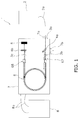
- FIG. 1 is a schematic diagram of a construction of the laser oscillator.
- a laser oscillator 1 includes a light source 2, first to third lenses 3a, 3b and 3c, first and second dichroic mirrors 4a and 4b, a damper 5, an optical fiber 6, a chassis 7 and a chiller 8.
- the light source 2 is configured to oscillate an excitation light, and can be composed of, for instance, a lamp, a semiconductor laser or so forth.
- the excitation light oscillated in the light source 2 is outputted through an excitation light transmission fiber 2a.
- the first lens 3a is a lens functioning as a collimator lens, and is disposed between the excitation light transmission fiber 2a and a first window part 7a of the chassis 7 to be described.
- the first lens 3a is configured to convert the excitation light, transmitted thereto from the light source 2, into a state of collimated light from a state of divergent light.
- the second lens 3b is a lens functioning as a condenser lens and a collimator lens, and is disposed between the first dichroic mirror 4a and a first end 67 of the optical fiber 6.
- the second lens 3b is configured to condense the excitation light converted into the state of collimated light by the first lens 3a and irradiate the condensed light to the optical fiber 6, and is also configured to convert the laser light irradiated from the optical fiber 6 into the state of collimated light.
- the third lens 3c is a lens functioning as a condenser lens and a collimator lens, and is disposed between the second dichroic mirror 4b and a second end 68 of the optical fiber 6.
- the third lens 3c is configured to convert the excitation light and the laser light from the optical fiber 6 into the state of collimated light, and is also configured to condense the laser light from the second dichroic mirror 4b and irradiate the condensed light to the optical fiber 6.
- the first dichroic mirror 4a is disposed between the first lens 3a and the second lens 3b.
- the first dichroic mirror 4a is designed to allow passage of the excitation light from the light source 2 and reflect the laser light from the optical fiber 6 so as to change its transmission direction.
- the second dichroic mirror 4b is disposed between the third lens 3c and the damper 5.
- the second dichroic mirror 4b is designed to allow passage of the excitation light from the optical fiber 6 and reflect the laser light from the optical fiber 6.
- the damper 5 is a member disposed downstream of the second dichroic mirror 4b so as to absorb the excitation light that has passed through the second dichroic mirror 4b.
- FIG. 2 is a cross-sectional side view of a first end 67 side part of the optical fiber 6
- FIG. 3 is a cross-sectional side view of a second end 68 side part of the optical fiber 6.
- the optical fiber 6 includes a first optical fiber body 61, a second optical fiber body 62, a first end cap 63, a second end cap 64 and a cooling member 65.
- the first optical fiber body 61 is a main portion of the optical fiber 6 and a laser light is produced in the first optical fiber body 61.
- FIG. 4 is a cross-sectional side view of a detailed construction of the first optical fiber body 61 and the second optical fiber body 62 on the first end 67 side of the optical fiber 6. As shown in FIG. 4 , the first optical fiber body 61 has a first core 611 and a first cladding 612 formed so as to enclose the first core 611.
- the first core 611 is made of fluoride glass doped with a rare earth element as a laser medium, and is preferably made of ZBLAN (ZrF 4 -BaF 2 -LaF 3 -AlF 3 -NaF) glass doped with erbium.
- the first cladding 612 is made of fluoride glass, and is preferably made of ZBLAN glass. It should be noted that the first cladding 612 has a refractive index lower than that of the first core 611 and is not doped with any laser medium.
- a first end surface 623 of the second optical fiber body 62 is joined to a first end surface 613 of the first optical fiber body 61.
- the second optical fiber body 62 has a second core 621 and a second cladding 622 formed so as to enclose the second core 621.
- the second optical fiber body 62 extends coaxially to the first optical fiber body 61, and has a diameter roughly equal to that of the first optical fiber body 61.
- the second cladding 622 has an outer diameter roughly equal to that of the first cladding 612. It should be noted that the second optical fiber body 62 is joined to the first optical fiber body 61 by thermal fusion boding.
- the second core 621 of the second optical fiber body 62 has a diameter larger than that of the first core 611 of the first optical fiber body 61. Additionally, the second optical fiber body 62 is designed to have a length whereby reflection of a laser light from the first optical fiber body 61 is prevented within the second core 621. Put differently, when entering the second core 621 from the first core 611, the laser light is irradiated from the second core 621 before being reflected within the second core 621. Moreover, the second core 622 is not doped with any rare earth element such as erbium as a laser medium, and thus, does not generate heat even when an excitation light is incident thereon. Put differently, no laser light is produced in the second fiber body 62.
- the first end cap 63 is joined to a second end surface 624 of the second optical fiber body 62.
- the first end cap 63 is joined to the second optical fiber body 62 by thermal fusion bonding.
- the first end cap 63 has light permeability of allowing an excitation light and a laser light to pass therethrough, and does not have deliquescence.
- the first end cap 36 preferably has a melting point higher than or equal to that of the second optical fiber body 62, and preferably has a thermal conductivity higher than that of the second fiber body 62 so as to cool the second end surface 624 of the second optical fiber body 62.
- the first end cap 63 preferably has a coefficient of linear expansion equivalent to that of the second optical fiber body 62 so as to be tightly joined to the second optical fiber body 62.
- the first end cap 63 can be a crystal of calcium fluoride or so forth.
- the first end cap 63 may be a crystal of quartz or so forth.
- the second end cap 64 is joined to a second end surface 614 of the first optical fiber body 61. Specifically, the second end cap 64 is joined to the first optical fiber body 61 by thermal fusion bonding.
- the second end cap 64 has the same construction as the aforementioned first end cap 63, and therefore, the detailed explanation thereof will not be described.
- the cooling member 65 is composed of two metallic plates 651a and 651b.
- the metallic plates 651a and 651b are made of, for instance, copper.
- the cooling member 65 is constructed to hold the first and second optical fiber bodies 61 and 62 such that the first and second optical fiber bodies 61 and 62 are interposed between the two metallic plates 651a and 651b. It should be noted that the first optical fiber body 61 is entirely interposed in and held by the cooling member 65. Put differently, the first optical fiber body 61 is not exposed from the respective metallic plates 651a and 651b in its lengthwise direction.
- the metallic plates 651a and 651b respectively have recesses on their opposed surfaces in order to hold the first and second optical fiber bodies 61 and 62.
- the first and second optical fiber bodies 61 and 62 are accommodated in an accommodation part delimited by the respective recesses, and are contacted to the respective metallic plates 651a and 651b within the accommodation part.
- the respective metallic plates 651a and 651b are contacted to each other at other parts except for the recesses.
- the metallic plate 651b disposed as the bottom side one of the metallic plates, is contacted to a base part of the chassis 7 to be described.
- the chassis 7 is a cubical box member and accommodates the second and third lenses 3b and 3c, the first and second dichroic mirrors 4a and 4b, the damper 5 and the optical fiber 6.
- the chassis 7 has the first window part 71a and a second window part 71b, both of which have light permeability.
- the excitation light from the light source 2 is transmitted into the chassis 7 through the first window part 7a and is fed to the optical fiber 6.
- the laser light from the optical fiber 6 is outputted to the outside of the chassis 7 through the second window part 7b.
- the chassis 7 has the base part (not shown in the drawing) on its bottom side.
- a flow path in which refrigerant flows is formed in the interior of the base part.
- the aforementioned metallic plate 651b is mounted onto the base part, and is thereby cooled. Additionally, the metallic plate 651a is contacted to the metallic plate 651b, and is thus cooled by heat transference therebetween.
- the interior of the chassis 7 is filled with nitrogen. Additionally, a desiccant is put in the interior of the chassis 7 in order to remove moisture in the interior of the chassis 7.
- the chiller 8 is connected to the chassis 7 through pipes 8a.
- the chiller 8 is configured to regulate the temperature of the refrigerant flowing within the base part of the chassis 7.
- the chiller 8 is configured to cool the refrigerant fed from the base part of the chassis 7 through one pipe 8a.
- the refrigerant cooled by the chiller 8 is returned to the base part of the chassis 7 through the other pipe 8a.
- An excitation light oscillated by the light source 2 is outputted from the excitation light transmission fiber 2a, is converted into the state of parallel light by the first lens 3a, and is transmitted into the chassis 7 through the first window part 7a.
- the excitation light transmitted into the chassis 7 penetrates through the first dichroic mirror 4a, is condensed by the second lens 3b, and enters the optical fiber 6 from its first end 67.
- the excitation light enters the optical fiber 6 from its first end cap 63.
- the excitation light After entering the optical fiber 6, the excitation light propagates through the first core 611 of the first optical fiber body 61. Erbium doped in the first core 611 is thereby excited and outputs a laser light. It should be noted that the excitation light also propagates through the second core 621 of the second optical fiber body 62, but a laser light is not outputted in the second core 621 because the second core 621 is not doped with erbium. The excitation light is gradually reduced in intensity during propagation through the first core 611. Then, the excitation light, irradiated from the second end 68 of the optical fiber 6, penetrates through the third lens 3c and the second dichroic mirror 4b and is absorbed by the damper 5.
- the laser light generated in the first core 611 of the first optical fiber body 61 is irradiated from the second end 68 of the optical fiber 6, and is converted into the state of parallel light by the third lens 3c. Then, the laser light is reflected by the second dichroic mirror 4b, is condensed by the third lens 3c, and enters the optical fiber 6 from the second end 68 side. After entering the optical fiber 6, the laser light propagates through the first core 611 of the first optical fiber body 61, and is irradiated from the first end 67 of the optical fiber 6.
- the laser light is converted into the state of parallel light by the second lens 3b, is reflected by the first dichroic mirror 4a, is changed in propagation direction so as to be directed to the second window part 7b, and is irradiated to the outside of the chassis 7 through the second window part 7b.
- the optical fiber 6 according to the present exemplary embodiment has the following features.
- the second end cap 64 is joined to the second end surface 614 of the first optical fiber body 61, but the construction composed of these elements is not particularly limited to this.
- a third optical fiber body 66 may be interposed between the first optical fiber body 61 and the second end cap 64.
- the third optical fiber body 66 is joined at a first end surface 663 to the second end surface 614 of the first optical fiber body 61, and is joined at a second end surface 664 to the second end cap 64.
- the third optical fiber body 66 can have the same construction as the second optical fiber body 62.
- the second core 621 of the second optical fiber body 62 does not contain any laser medium, but its configuration regarding containment of a laser medium is not limited to this.
- the second core 621 of the second optical fiber body 62 may contain a laser medium with a mass content lower than that of the laser medium contained in the first core 611 of the first optical fiber body 61.
- the mass content of the laser medium contained in the second core 621 depends on the intensity of an excitation light, the sort of a laser medium and so forth, but is preferably set such that the second core 621 is not damaged by generation of heat.
- the first optical fiber body 61 is designed to include the first core 611 and the first cladding 612 formed so as to enclose the first core 611, but its construction is not limited to this.
- the first optical fiber body 61 can be formed as a so-called double cladding fiber.
- the first cladding 612 may be composed of an inner cladding and an outer cladding enclosing the inner cladding.
Landscapes
- Physics & Mathematics (AREA)
- Electromagnetism (AREA)
- Engineering & Computer Science (AREA)
- Plasma & Fusion (AREA)
- Optics & Photonics (AREA)
- Microelectronics & Electronic Packaging (AREA)
- Lasers (AREA)
- Optical Couplings Of Light Guides (AREA)
- Optical Fibers, Optical Fiber Cores, And Optical Fiber Bundles (AREA)
Applications Claiming Priority (2)
| Application Number | Priority Date | Filing Date | Title |
|---|---|---|---|
| JP2013067938A JP5588534B1 (ja) | 2013-03-28 | 2013-03-28 | 光ファイバ、及びこれを用いたレーザ発振器 |
| PCT/JP2014/057806 WO2014156972A1 (ja) | 2013-03-28 | 2014-03-20 | 光ファイバ、及びこれを用いたレーザ発振器 |
Publications (3)
| Publication Number | Publication Date |
|---|---|
| EP2980934A1 true EP2980934A1 (de) | 2016-02-03 |
| EP2980934A4 EP2980934A4 (de) | 2016-05-11 |
| EP2980934B1 EP2980934B1 (de) | 2019-08-14 |
Family
ID=51617934
Family Applications (1)
| Application Number | Title | Priority Date | Filing Date |
|---|---|---|---|
| EP14775306.5A Active EP2980934B1 (de) | 2013-03-28 | 2014-03-20 | Glasfaser und laseroszillator damit |
Country Status (8)
| Country | Link |
|---|---|
| US (1) | US9425577B2 (de) |
| EP (1) | EP2980934B1 (de) |
| JP (1) | JP5588534B1 (de) |
| KR (1) | KR101803345B1 (de) |
| CN (1) | CN104981952B (de) |
| CA (1) | CA2907629C (de) |
| TW (1) | TWI597909B (de) |
| WO (1) | WO2014156972A1 (de) |
Families Citing this family (8)
| Publication number | Priority date | Publication date | Assignee | Title |
|---|---|---|---|---|
| JP6579569B2 (ja) * | 2014-10-20 | 2019-09-25 | 三星ダイヤモンド工業株式会社 | 固体レーザ素子 |
| JP6579568B2 (ja) * | 2014-10-20 | 2019-09-25 | 三星ダイヤモンド工業株式会社 | 固体レーザ素子 |
| US11043785B2 (en) * | 2016-10-14 | 2021-06-22 | The Government Of The United States Of America, As Represented By The Secretary Of The Navy | Nanoparticle doping for lasers and amplifiers operating at eye-safer wavelengths, and/or exhibiting reduced Stimulated Brillouin Scattering |
| CN107015320B (zh) * | 2017-05-17 | 2019-07-26 | 中国兵器装备研究院 | 一种高功率光纤端帽的制造方法 |
| WO2019002212A1 (en) * | 2017-06-27 | 2019-01-03 | Smr Patents Sarl | LASER AUTOMOBILE HEADLIGHT APPARATUS |
| WO2020184603A1 (ja) | 2019-03-12 | 2020-09-17 | 古河電気工業株式会社 | 光学部品および半導体レーザモジュール |
| JP6836043B2 (ja) * | 2019-07-26 | 2021-02-24 | 株式会社金門光波 | ファイバーレーザー装置 |
| CN115657196B (zh) * | 2022-10-10 | 2025-11-25 | 中国科学院上海光学精密机械研究所 | 一种中波红外复合玻璃光纤及其制备方法 |
Family Cites Families (19)
| Publication number | Priority date | Publication date | Assignee | Title |
|---|---|---|---|---|
| JPH0795127B2 (ja) * | 1986-05-14 | 1995-10-11 | 株式会社ブリヂストン | 光伝送ホース |
| CN1141764C (zh) * | 1994-02-18 | 2004-03-10 | 英国电讯有限公司 | 增益控制光纤放大器 |
| US6137813A (en) * | 1998-04-10 | 2000-10-24 | Hughes Electronics Corporation | Yb-doped fiber laser operating near EDFA absorption band |
| KR100283954B1 (ko) * | 1998-10-13 | 2001-03-02 | 윤종용 | 광증폭기용 광섬유 |
| US6347100B1 (en) * | 1999-01-04 | 2002-02-12 | Sdl, Inc. | Short wavelength fiber laser |
| JP2001274489A (ja) * | 2000-03-27 | 2001-10-05 | Toshiba Corp | 光ファイバ放熱装置 |
| DE10302031A1 (de) * | 2003-01-21 | 2004-09-23 | Evotec Oai Ag | Faser-Laser |
| JP2005303166A (ja) | 2004-04-15 | 2005-10-27 | Fujikura Ltd | 光ファイバ端面構造、光ファイバレーザ及びレーザ加工装置 |
| WO2007103898A2 (en) * | 2006-03-03 | 2007-09-13 | Aculight Corporation | Diode-laser-pump module with integrated signal ports for pumping amplifying fibers |
| JP2007273842A (ja) | 2006-03-31 | 2007-10-18 | Miyachi Technos Corp | ファイバレーザ発振器及びファイバレーザ加工装置 |
| JP2009212441A (ja) * | 2008-03-06 | 2009-09-17 | Fujikura Ltd | ポンプコンバイナ |
| JP2010141283A (ja) | 2008-07-08 | 2010-06-24 | Central Glass Co Ltd | 広帯域な波長可変レーザ装置 |
| US8508843B2 (en) * | 2008-10-31 | 2013-08-13 | Electro Scientific Industries, Inc. | Laser systems with doped fiber components |
| JP5294114B2 (ja) | 2009-01-26 | 2013-09-18 | 株式会社メガオプト | 光学モジュール |
| US8422024B2 (en) * | 2011-06-01 | 2013-04-16 | Honeywell International Inc. | High performance hollow-core optical-fiber filter for optical rotation sensing |
| US8682126B2 (en) | 2011-07-29 | 2014-03-25 | Ipg Photonics Corporation | Method for assembling high power fiber laser system and module realizing the method |
| KR20130104838A (ko) * | 2012-03-15 | 2013-09-25 | 한국전자통신연구원 | 광 결합장치 및 그를 구비한 능동 광모듈 |
| CN102778729B (zh) * | 2012-07-31 | 2014-10-22 | 清华大学 | 高光束质量信号光光纤合束器及其制作方法 |
| CN102866462B (zh) * | 2012-08-31 | 2014-05-21 | 董浩 | 实现lp01模场直径低损耗变换的光纤模场适配器 |
-
2013
- 2013-03-28 JP JP2013067938A patent/JP5588534B1/ja not_active Expired - Fee Related
-
2014
- 2014-03-20 CN CN201480007710.5A patent/CN104981952B/zh not_active Expired - Fee Related
- 2014-03-20 WO PCT/JP2014/057806 patent/WO2014156972A1/ja not_active Ceased
- 2014-03-20 CA CA2907629A patent/CA2907629C/en active Active
- 2014-03-20 KR KR1020157019915A patent/KR101803345B1/ko not_active Expired - Fee Related
- 2014-03-20 US US14/774,135 patent/US9425577B2/en not_active Expired - Fee Related
- 2014-03-20 EP EP14775306.5A patent/EP2980934B1/de active Active
- 2014-03-25 TW TW103111104A patent/TWI597909B/zh not_active IP Right Cessation
Also Published As
| Publication number | Publication date |
|---|---|
| US9425577B2 (en) | 2016-08-23 |
| KR101803345B1 (ko) | 2017-11-30 |
| WO2014156972A1 (ja) | 2014-10-02 |
| TWI597909B (zh) | 2017-09-01 |
| CN104981952B (zh) | 2018-02-09 |
| CA2907629A1 (en) | 2014-10-02 |
| CA2907629C (en) | 2018-03-06 |
| EP2980934B1 (de) | 2019-08-14 |
| TW201448385A (zh) | 2014-12-16 |
| KR20150100841A (ko) | 2015-09-02 |
| JP2014192412A (ja) | 2014-10-06 |
| JP5588534B1 (ja) | 2014-09-10 |
| US20160043523A1 (en) | 2016-02-11 |
| CN104981952A (zh) | 2015-10-14 |
| EP2980934A4 (de) | 2016-05-11 |
Similar Documents
| Publication | Publication Date | Title |
|---|---|---|
| EP2980934B1 (de) | Glasfaser und laseroszillator damit | |
| JP5648131B2 (ja) | パッケージ化した光ファイバ部品及びその製造方法 | |
| CN105723576A (zh) | 光纤激光装置 | |
| JP2011186399A (ja) | 光ファイバ接続構造、レーザ照射装置およびレーザ加工装置 | |
| TW201304333A (zh) | Q-切換引發之增益切換鉺脈衝雷射系統 | |
| TWI652516B (zh) | Fiber optic device | |
| JP2010147108A (ja) | ファイバレーザ装置、レーザ加工装置、及びレーザ加工方法 | |
| TWI661627B (zh) | 光纖冷卻裝置及雷射振盪器 | |
| KR100256435B1 (ko) | 광파이버의 광소스 및 저 시간적 간섭성을 갖는 광의 발생방법 | |
| JP2021005659A (ja) | ファイバレーザ発振器及びファイバレーザ発振器用筐体 | |
| Nguyen et al. | All fiber approach to solid-state laser cooling | |
| EP3719941B1 (de) | Planarer wellenleiter und laserverstärker | |
| JP6799328B2 (ja) | 光ファイバ保持装置及びこれを有するレーザ発振器 | |
| JP2015153919A (ja) | 光ファイバ、及びこれを用いたレーザ発振器 | |
| JP2015126072A (ja) | 光ファイバ、及び冷却装置 | |
| JPWO2006098313A1 (ja) | 光増幅器およびレーザ装置 | |
| Sato et al. | Laser Oscillation of Nd-doped Optical Gain Medium Based on Silica Glass with a High Thermal Shock Parameter for High-Average-Power Laser | |
| CN104518420A (zh) | 一种提高激光振荡器输出功率的装置及方法 | |
| JP6792716B2 (ja) | 加熱条件の設定方法、ファイバブラッググレーティングの製造方法、及びファイバレーザシステムの製造方法 | |
| JP2021005660A (ja) | ファイバレーザ発振器 | |
| Robin | Novel approaches to power scaling of single-frequency photonic crystal fiber amplifiers | |
| JPH11281803A (ja) | 光強度の制限方法及び制限器 | |
| JP2014219524A (ja) | 光吸収機能を有する光ファイバ | |
| JP2021005658A (ja) | ファイバレーザ発振器及びファイバレーザ発振器用筐体 | |
| Henninot et al. | Thermally Induced Spatial Soliton in Dye Doped Nematic Liquid Crystal |
Legal Events
| Date | Code | Title | Description |
|---|---|---|---|
| PUAI | Public reference made under article 153(3) epc to a published international application that has entered the european phase |
Free format text: ORIGINAL CODE: 0009012 |
|
| 17P | Request for examination filed |
Effective date: 20150917 |
|
| AK | Designated contracting states |
Kind code of ref document: A1 Designated state(s): AL AT BE BG CH CY CZ DE DK EE ES FI FR GB GR HR HU IE IS IT LI LT LU LV MC MK MT NL NO PL PT RO RS SE SI SK SM TR |
|
| AX | Request for extension of the european patent |
Extension state: BA ME |
|
| A4 | Supplementary search report drawn up and despatched |
Effective date: 20160412 |
|
| RIC1 | Information provided on ipc code assigned before grant |
Ipc: H01S 3/042 20060101ALI20160406BHEP Ipc: H01S 3/17 20060101ALN20160406BHEP Ipc: G02B 6/00 20060101AFI20160406BHEP Ipc: H01S 3/00 20060101ALN20160406BHEP Ipc: H01S 3/04 20060101ALN20160406BHEP Ipc: G02B 6/02 20060101ALI20160406BHEP Ipc: H01S 3/067 20060101ALI20160406BHEP Ipc: H01S 3/16 20060101ALN20160406BHEP |
|
| DAX | Request for extension of the european patent (deleted) | ||
| REG | Reference to a national code |
Ref country code: DE Ref legal event code: R079 Ref document number: 602014051788 Country of ref document: DE Free format text: PREVIOUS MAIN CLASS: H01S0003070000 Ipc: H01S0003042000 |
|
| GRAP | Despatch of communication of intention to grant a patent |
Free format text: ORIGINAL CODE: EPIDOSNIGR1 |
|
| STAA | Information on the status of an ep patent application or granted ep patent |
Free format text: STATUS: GRANT OF PATENT IS INTENDED |
|
| RIC1 | Information provided on ipc code assigned before grant |
Ipc: H01S 3/00 20060101ALN20190124BHEP Ipc: H01S 3/16 20060101ALN20190124BHEP Ipc: H01S 3/042 20060101AFI20190124BHEP Ipc: H01S 3/17 20060101ALN20190124BHEP Ipc: G02B 6/02 20060101ALI20190124BHEP Ipc: G02B 6/00 20060101ALI20190124BHEP Ipc: H01S 3/04 20060101ALN20190124BHEP Ipc: H01S 3/067 20060101ALI20190124BHEP |
|
| INTG | Intention to grant announced |
Effective date: 20190227 |
|
| GRAS | Grant fee paid |
Free format text: ORIGINAL CODE: EPIDOSNIGR3 |
|
| GRAA | (expected) grant |
Free format text: ORIGINAL CODE: 0009210 |
|
| STAA | Information on the status of an ep patent application or granted ep patent |
Free format text: STATUS: THE PATENT HAS BEEN GRANTED |
|
| AK | Designated contracting states |
Kind code of ref document: B1 Designated state(s): AL AT BE BG CH CY CZ DE DK EE ES FI FR GB GR HR HU IE IS IT LI LT LU LV MC MK MT NL NO PL PT RO RS SE SI SK SM TR |
|
| REG | Reference to a national code |
Ref country code: GB Ref legal event code: FG4D |
|
| REG | Reference to a national code |
Ref country code: CH Ref legal event code: EP Ref country code: AT Ref legal event code: REF Ref document number: 1168134 Country of ref document: AT Kind code of ref document: T Effective date: 20190815 |
|
| REG | Reference to a national code |
Ref country code: IE Ref legal event code: FG4D |
|
| REG | Reference to a national code |
Ref country code: DE Ref legal event code: R096 Ref document number: 602014051788 Country of ref document: DE |
|
| REG | Reference to a national code |
Ref country code: NL Ref legal event code: MP Effective date: 20190814 |
|
| REG | Reference to a national code |
Ref country code: LT Ref legal event code: MG4D |
|
| PG25 | Lapsed in a contracting state [announced via postgrant information from national office to epo] |
Ref country code: LT Free format text: LAPSE BECAUSE OF FAILURE TO SUBMIT A TRANSLATION OF THE DESCRIPTION OR TO PAY THE FEE WITHIN THE PRESCRIBED TIME-LIMIT Effective date: 20190814 Ref country code: HR Free format text: LAPSE BECAUSE OF FAILURE TO SUBMIT A TRANSLATION OF THE DESCRIPTION OR TO PAY THE FEE WITHIN THE PRESCRIBED TIME-LIMIT Effective date: 20190814 Ref country code: FI Free format text: LAPSE BECAUSE OF FAILURE TO SUBMIT A TRANSLATION OF THE DESCRIPTION OR TO PAY THE FEE WITHIN THE PRESCRIBED TIME-LIMIT Effective date: 20190814 Ref country code: PT Free format text: LAPSE BECAUSE OF FAILURE TO SUBMIT A TRANSLATION OF THE DESCRIPTION OR TO PAY THE FEE WITHIN THE PRESCRIBED TIME-LIMIT Effective date: 20191216 Ref country code: SE Free format text: LAPSE BECAUSE OF FAILURE TO SUBMIT A TRANSLATION OF THE DESCRIPTION OR TO PAY THE FEE WITHIN THE PRESCRIBED TIME-LIMIT Effective date: 20190814 Ref country code: NO Free format text: LAPSE BECAUSE OF FAILURE TO SUBMIT A TRANSLATION OF THE DESCRIPTION OR TO PAY THE FEE WITHIN THE PRESCRIBED TIME-LIMIT Effective date: 20191114 Ref country code: BG Free format text: LAPSE BECAUSE OF FAILURE TO SUBMIT A TRANSLATION OF THE DESCRIPTION OR TO PAY THE FEE WITHIN THE PRESCRIBED TIME-LIMIT Effective date: 20191114 Ref country code: NL Free format text: LAPSE BECAUSE OF FAILURE TO SUBMIT A TRANSLATION OF THE DESCRIPTION OR TO PAY THE FEE WITHIN THE PRESCRIBED TIME-LIMIT Effective date: 20190814 |
|
| REG | Reference to a national code |
Ref country code: AT Ref legal event code: MK05 Ref document number: 1168134 Country of ref document: AT Kind code of ref document: T Effective date: 20190814 |
|
| PG25 | Lapsed in a contracting state [announced via postgrant information from national office to epo] |
Ref country code: RS Free format text: LAPSE BECAUSE OF FAILURE TO SUBMIT A TRANSLATION OF THE DESCRIPTION OR TO PAY THE FEE WITHIN THE PRESCRIBED TIME-LIMIT Effective date: 20190814 Ref country code: IS Free format text: LAPSE BECAUSE OF FAILURE TO SUBMIT A TRANSLATION OF THE DESCRIPTION OR TO PAY THE FEE WITHIN THE PRESCRIBED TIME-LIMIT Effective date: 20191214 Ref country code: LV Free format text: LAPSE BECAUSE OF FAILURE TO SUBMIT A TRANSLATION OF THE DESCRIPTION OR TO PAY THE FEE WITHIN THE PRESCRIBED TIME-LIMIT Effective date: 20190814 Ref country code: ES Free format text: LAPSE BECAUSE OF FAILURE TO SUBMIT A TRANSLATION OF THE DESCRIPTION OR TO PAY THE FEE WITHIN THE PRESCRIBED TIME-LIMIT Effective date: 20190814 Ref country code: AL Free format text: LAPSE BECAUSE OF FAILURE TO SUBMIT A TRANSLATION OF THE DESCRIPTION OR TO PAY THE FEE WITHIN THE PRESCRIBED TIME-LIMIT Effective date: 20190814 Ref country code: GR Free format text: LAPSE BECAUSE OF FAILURE TO SUBMIT A TRANSLATION OF THE DESCRIPTION OR TO PAY THE FEE WITHIN THE PRESCRIBED TIME-LIMIT Effective date: 20191115 |
|
| PG25 | Lapsed in a contracting state [announced via postgrant information from national office to epo] |
Ref country code: TR Free format text: LAPSE BECAUSE OF FAILURE TO SUBMIT A TRANSLATION OF THE DESCRIPTION OR TO PAY THE FEE WITHIN THE PRESCRIBED TIME-LIMIT Effective date: 20190814 |
|
| PG25 | Lapsed in a contracting state [announced via postgrant information from national office to epo] |
Ref country code: AT Free format text: LAPSE BECAUSE OF FAILURE TO SUBMIT A TRANSLATION OF THE DESCRIPTION OR TO PAY THE FEE WITHIN THE PRESCRIBED TIME-LIMIT Effective date: 20190814 Ref country code: DK Free format text: LAPSE BECAUSE OF FAILURE TO SUBMIT A TRANSLATION OF THE DESCRIPTION OR TO PAY THE FEE WITHIN THE PRESCRIBED TIME-LIMIT Effective date: 20190814 Ref country code: PL Free format text: LAPSE BECAUSE OF FAILURE TO SUBMIT A TRANSLATION OF THE DESCRIPTION OR TO PAY THE FEE WITHIN THE PRESCRIBED TIME-LIMIT Effective date: 20190814 Ref country code: EE Free format text: LAPSE BECAUSE OF FAILURE TO SUBMIT A TRANSLATION OF THE DESCRIPTION OR TO PAY THE FEE WITHIN THE PRESCRIBED TIME-LIMIT Effective date: 20190814 Ref country code: IT Free format text: LAPSE BECAUSE OF FAILURE TO SUBMIT A TRANSLATION OF THE DESCRIPTION OR TO PAY THE FEE WITHIN THE PRESCRIBED TIME-LIMIT Effective date: 20190814 Ref country code: RO Free format text: LAPSE BECAUSE OF FAILURE TO SUBMIT A TRANSLATION OF THE DESCRIPTION OR TO PAY THE FEE WITHIN THE PRESCRIBED TIME-LIMIT Effective date: 20190814 |
|
| PGFP | Annual fee paid to national office [announced via postgrant information from national office to epo] |
Ref country code: DE Payment date: 20200320 Year of fee payment: 7 |
|
| PG25 | Lapsed in a contracting state [announced via postgrant information from national office to epo] |
Ref country code: SM Free format text: LAPSE BECAUSE OF FAILURE TO SUBMIT A TRANSLATION OF THE DESCRIPTION OR TO PAY THE FEE WITHIN THE PRESCRIBED TIME-LIMIT Effective date: 20190814 Ref country code: IS Free format text: LAPSE BECAUSE OF FAILURE TO SUBMIT A TRANSLATION OF THE DESCRIPTION OR TO PAY THE FEE WITHIN THE PRESCRIBED TIME-LIMIT Effective date: 20200224 Ref country code: CZ Free format text: LAPSE BECAUSE OF FAILURE TO SUBMIT A TRANSLATION OF THE DESCRIPTION OR TO PAY THE FEE WITHIN THE PRESCRIBED TIME-LIMIT Effective date: 20190814 Ref country code: SK Free format text: LAPSE BECAUSE OF FAILURE TO SUBMIT A TRANSLATION OF THE DESCRIPTION OR TO PAY THE FEE WITHIN THE PRESCRIBED TIME-LIMIT Effective date: 20190814 |
|
| REG | Reference to a national code |
Ref country code: DE Ref legal event code: R097 Ref document number: 602014051788 Country of ref document: DE |
|
| PLBE | No opposition filed within time limit |
Free format text: ORIGINAL CODE: 0009261 |
|
| STAA | Information on the status of an ep patent application or granted ep patent |
Free format text: STATUS: NO OPPOSITION FILED WITHIN TIME LIMIT |
|
| PG2D | Information on lapse in contracting state deleted |
Ref country code: IS |
|
| 26N | No opposition filed |
Effective date: 20200603 |
|
| PG25 | Lapsed in a contracting state [announced via postgrant information from national office to epo] |
Ref country code: SI Free format text: LAPSE BECAUSE OF FAILURE TO SUBMIT A TRANSLATION OF THE DESCRIPTION OR TO PAY THE FEE WITHIN THE PRESCRIBED TIME-LIMIT Effective date: 20190814 |
|
| PG25 | Lapsed in a contracting state [announced via postgrant information from national office to epo] |
Ref country code: MC Free format text: LAPSE BECAUSE OF FAILURE TO SUBMIT A TRANSLATION OF THE DESCRIPTION OR TO PAY THE FEE WITHIN THE PRESCRIBED TIME-LIMIT Effective date: 20190814 |
|
| REG | Reference to a national code |
Ref country code: CH Ref legal event code: PL |
|
| REG | Reference to a national code |
Ref country code: BE Ref legal event code: MM Effective date: 20200331 |
|
| PG25 | Lapsed in a contracting state [announced via postgrant information from national office to epo] |
Ref country code: LU Free format text: LAPSE BECAUSE OF NON-PAYMENT OF DUE FEES Effective date: 20200320 |
|
| PG25 | Lapsed in a contracting state [announced via postgrant information from national office to epo] |
Ref country code: IE Free format text: LAPSE BECAUSE OF NON-PAYMENT OF DUE FEES Effective date: 20200320 Ref country code: LI Free format text: LAPSE BECAUSE OF NON-PAYMENT OF DUE FEES Effective date: 20200331 Ref country code: CH Free format text: LAPSE BECAUSE OF NON-PAYMENT OF DUE FEES Effective date: 20200331 |
|
| PG25 | Lapsed in a contracting state [announced via postgrant information from national office to epo] |
Ref country code: BE Free format text: LAPSE BECAUSE OF NON-PAYMENT OF DUE FEES Effective date: 20200331 |
|
| GBPC | Gb: european patent ceased through non-payment of renewal fee |
Effective date: 20200320 |
|
| PG25 | Lapsed in a contracting state [announced via postgrant information from national office to epo] |
Ref country code: GB Free format text: LAPSE BECAUSE OF NON-PAYMENT OF DUE FEES Effective date: 20200320 |
|
| REG | Reference to a national code |
Ref country code: DE Ref legal event code: R119 Ref document number: 602014051788 Country of ref document: DE |
|
| PG25 | Lapsed in a contracting state [announced via postgrant information from national office to epo] |
Ref country code: DE Free format text: LAPSE BECAUSE OF NON-PAYMENT OF DUE FEES Effective date: 20211001 |
|
| PG25 | Lapsed in a contracting state [announced via postgrant information from national office to epo] |
Ref country code: MT Free format text: LAPSE BECAUSE OF FAILURE TO SUBMIT A TRANSLATION OF THE DESCRIPTION OR TO PAY THE FEE WITHIN THE PRESCRIBED TIME-LIMIT Effective date: 20190814 Ref country code: CY Free format text: LAPSE BECAUSE OF FAILURE TO SUBMIT A TRANSLATION OF THE DESCRIPTION OR TO PAY THE FEE WITHIN THE PRESCRIBED TIME-LIMIT Effective date: 20190814 |
|
| PG25 | Lapsed in a contracting state [announced via postgrant information from national office to epo] |
Ref country code: MK Free format text: LAPSE BECAUSE OF FAILURE TO SUBMIT A TRANSLATION OF THE DESCRIPTION OR TO PAY THE FEE WITHIN THE PRESCRIBED TIME-LIMIT Effective date: 20190814 |
|
| PGFP | Annual fee paid to national office [announced via postgrant information from national office to epo] |
Ref country code: FR Payment date: 20230208 Year of fee payment: 10 |
|
| PG25 | Lapsed in a contracting state [announced via postgrant information from national office to epo] |
Ref country code: FR Free format text: LAPSE BECAUSE OF NON-PAYMENT OF DUE FEES Effective date: 20240331 |
|
| PG25 | Lapsed in a contracting state [announced via postgrant information from national office to epo] |
Ref country code: FR Free format text: LAPSE BECAUSE OF NON-PAYMENT OF DUE FEES Effective date: 20240331 |