EP2980962A2 - Elektrische maschine - Google Patents
Elektrische maschine Download PDFInfo
- Publication number
- EP2980962A2 EP2980962A2 EP14785383.2A EP14785383A EP2980962A2 EP 2980962 A2 EP2980962 A2 EP 2980962A2 EP 14785383 A EP14785383 A EP 14785383A EP 2980962 A2 EP2980962 A2 EP 2980962A2
- Authority
- EP
- European Patent Office
- Prior art keywords
- rotor core
- permanent magnets
- flux barrier
- rotor
- embedding holes
- Prior art date
- Legal status (The legal status is an assumption and is not a legal conclusion. Google has not performed a legal analysis and makes no representation as to the accuracy of the status listed.)
- Granted
Links
- 230000004907 flux Effects 0.000 claims description 53
- 230000004888 barrier function Effects 0.000 claims description 49
- 238000001816 cooling Methods 0.000 claims description 27
- 239000000853 adhesive Substances 0.000 description 25
- 230000001070 adhesive effect Effects 0.000 description 25
- 229910000831 Steel Inorganic materials 0.000 description 8
- 239000010959 steel Substances 0.000 description 8
- 238000004891 communication Methods 0.000 description 5
- 238000010276 construction Methods 0.000 description 3
- 238000012840 feeding operation Methods 0.000 description 3
- 230000006872 improvement Effects 0.000 description 3
- 230000004048 modification Effects 0.000 description 3
- 238000012986 modification Methods 0.000 description 3
- 230000001360 synchronised effect Effects 0.000 description 3
- XEEYBQQBJWHFJM-UHFFFAOYSA-N Iron Chemical compound [Fe] XEEYBQQBJWHFJM-UHFFFAOYSA-N 0.000 description 2
- 239000012141 concentrate Substances 0.000 description 2
- 239000000463 material Substances 0.000 description 2
- 238000000034 method Methods 0.000 description 2
- 230000008569 process Effects 0.000 description 2
- 229910052692 Dysprosium Inorganic materials 0.000 description 1
- 229910052779 Neodymium Inorganic materials 0.000 description 1
- 230000002411 adverse Effects 0.000 description 1
- KBQHZAAAGSGFKK-UHFFFAOYSA-N dysprosium atom Chemical compound [Dy] KBQHZAAAGSGFKK-UHFFFAOYSA-N 0.000 description 1
- 230000002349 favourable effect Effects 0.000 description 1
- 238000003780 insertion Methods 0.000 description 1
- 230000037431 insertion Effects 0.000 description 1
- 229910052742 iron Inorganic materials 0.000 description 1
- QEFYFXOXNSNQGX-UHFFFAOYSA-N neodymium atom Chemical compound [Nd] QEFYFXOXNSNQGX-UHFFFAOYSA-N 0.000 description 1
- 230000000149 penetrating effect Effects 0.000 description 1
- 230000010349 pulsation Effects 0.000 description 1
- 229910052761 rare earth metal Inorganic materials 0.000 description 1
- 150000002910 rare earth metals Chemical class 0.000 description 1
- 239000011347 resin Substances 0.000 description 1
- 229920005989 resin Polymers 0.000 description 1
Images

Classifications
-
- H—ELECTRICITY
- H02—GENERATION; CONVERSION OR DISTRIBUTION OF ELECTRIC POWER
- H02K—DYNAMO-ELECTRIC MACHINES
- H02K1/00—Details of the magnetic circuit
- H02K1/06—Details of the magnetic circuit characterised by the shape, form or construction
- H02K1/22—Rotating parts of the magnetic circuit
- H02K1/27—Rotor cores with permanent magnets
- H02K1/2706—Inner rotors
- H02K1/272—Inner rotors the magnetisation axis of the magnets being perpendicular to the rotor axis
- H02K1/274—Inner rotors the magnetisation axis of the magnets being perpendicular to the rotor axis the rotor consisting of two or more circumferentially positioned magnets
- H02K1/2753—Inner rotors the magnetisation axis of the magnets being perpendicular to the rotor axis the rotor consisting of two or more circumferentially positioned magnets the rotor consisting of magnets or groups of magnets arranged with alternating polarity
- H02K1/276—Magnets embedded in the magnetic core, e.g. interior permanent magnets [IPM]
- H02K1/2766—Magnets embedded in the magnetic core, e.g. interior permanent magnets [IPM] having a flux concentration effect
-
- H—ELECTRICITY
- H02—GENERATION; CONVERSION OR DISTRIBUTION OF ELECTRIC POWER
- H02K—DYNAMO-ELECTRIC MACHINES
- H02K1/00—Details of the magnetic circuit
- H02K1/06—Details of the magnetic circuit characterised by the shape, form or construction
- H02K1/22—Rotating parts of the magnetic circuit
- H02K1/32—Rotating parts of the magnetic circuit with channels or ducts for flow of cooling medium
-
- H—ELECTRICITY
- H02—GENERATION; CONVERSION OR DISTRIBUTION OF ELECTRIC POWER
- H02K—DYNAMO-ELECTRIC MACHINES
- H02K21/00—Synchronous motors having permanent magnets; Synchronous generators having permanent magnets
- H02K21/02—Details
- H02K21/04—Windings on magnets for additional excitation ; Windings and magnets for additional excitation
- H02K21/046—Windings on magnets for additional excitation ; Windings and magnets for additional excitation with rotating permanent magnets and stationary field winding
-
- H—ELECTRICITY
- H02—GENERATION; CONVERSION OR DISTRIBUTION OF ELECTRIC POWER
- H02K—DYNAMO-ELECTRIC MACHINES
- H02K5/00—Casings; Enclosures; Supports
- H02K5/04—Casings or enclosures characterised by the shape, form or construction thereof
- H02K5/20—Casings or enclosures characterised by the shape, form or construction thereof with channels or ducts for flow of cooling medium
- H02K5/203—Casings or enclosures characterised by the shape, form or construction thereof with channels or ducts for flow of cooling medium specially adapted for liquids, e.g. cooling jackets
-
- H—ELECTRICITY
- H02—GENERATION; CONVERSION OR DISTRIBUTION OF ELECTRIC POWER
- H02K—DYNAMO-ELECTRIC MACHINES
- H02K9/00—Arrangements for cooling or ventilating
- H02K9/19—Arrangements for cooling or ventilating for machines with closed casing and closed-circuit cooling using a liquid cooling medium, e.g. oil
Definitions
- the present invention relates to a motor, particularly, to an improvement in a fixation structure of a permanent magnet used in a rotor of a permanent magnet-embedded synchronous motor.
- the adhesive is typically fed in a part formed near an inner circumference of the rotor core in each of the gaps formed between the holes and the permanent magnets.
- the permanent magnets are pressed toward an outer circumference of the rotor core, so that the permanent magnets are respectively in contact with the inner surfaces of the holes near the outer circumference of the rotor core. Accordingly, no gap is formed near the outer circumference of the rotor core to block filling with the adhesive.
- the adhesive is fed mainly in the gap formed near the inner circumference of the rotor core.
- Patent Literatures 1 and 2 fail to describe cooling of the permanent magnets and the rotor core, which may cause an insufficient cooling.
- An object of the invention is to provide a motor capable of easily feeding an adhesive and reliably holding a permanent magnet.
- a motor includes: an annular stator attached in a housing; a rotor that is disposed in the stator and is rotatably supported by the housing; and a plurality of permanent magnets embedded in a rotor core of the rotor, in which the rotor core includes embedding holes respectively in which the permanent magnets are fitted, and each of the embedding holes is formed with filling holes, which are each continuous in an axial direction of the rotor core, at diagonal positions of each of the permanent magnets.
- the rotor core includes a flux barrier defined by an end of each of the embedding holes, and the flux barrier defines an oil path through which a cooling oil flows.
- the rotor core includes a flux barrier defined by an end of each of the embedding holes, and the flux barrier defines a support that supports each of the permanent magnets.
- the support is opposite the filling hole across a corner of each of the permanent magnets in a form of a prism.
- a motor includes: an annular stator attached in a housing; a rotor that is disposed in the stator and is rotatably supported by the housing; and a plurality of cross-sectionally rectangular permanent magnets embedded in a rotor core of the rotor, in which a pair of ones of the permanent magnets, which are disposed in a V-shape seen from an axial center of the rotor, define one magnetic pole,
- the rotor core includes: embedding holes respectively in which the permanent magnets are fitted; an outer-circumferential flux barrier that is defined by a first end of each of the embedding holes and is positioned near an outer circumference of the rotor core; and an inner flux barrier that is defined by a second end of each of the embedding holes and is positioned on an inner side of each of the embedding holes than the outer-circumferential flux barrier, each of the embedding holes is formed with filling holes, which are each continuous in an axial direction of the
- each of the permanent magnets is attached to the rotor core only at two of diagonal positions, a feed amount of an adhesive and the like can significantly be reduced and a feeding operation can be conducted rapidly and easily.
- the permanent magnets are respectively fitted in the embedding holes, even though fixation is made by attachment only at two positions, the fixation can sufficiently withstand centrifugal force generated when the rotor is rotated, so that the permanent magnets can securely be held in the embedding holes.
- the flux barrier since the flux barrier is not filled with the adhesive, the flux barrier is reliably usable as an oil path through which a cooling oil flows, so that the permanent magnets and the rotor core can favorably be cooled.
- the permanent magnets respectively fitted in the embedding holes can more securely be fixed, so that the permanent magnets can more reliably be prevented from dropping off in the respective embedding holes.
- the filling hole and the support can be formed in a sufficient size at positions where the filling hole and the support do not mutually interfere, so that a fixation strength and durability can be improved.
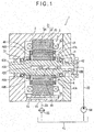
- Fig. 1 is a cross sectional view of an entire motor 1 in the exemplary embodiment.
- Fig. 2 illustrates a rotor core 41 of the motor 1.
- the motor 1 includes an annular stator 3 attached in a housing 2 and a rotor 4 disposed in the stator 3 and rotatably supported in the housing 2.
- the motor 1 is provided in a form of a permanent magnet-embedded synchronous motor in which a permanent magnet 43 is embedded in a rotor core 41 of the rotor 4.
- the stator 3 includes a stator core 31 provided by layering a great number of electromagnetic steel plates in an axial direction of the stator 3.
- the stator core 31 includes a yoke 32 continuous in a circumferential direction on an outer circumference and a plurality of teeth 33 projecting from the yoke 32 toward the rotor 4 in the center of the motor 1.
- the plurality of teeth 33 are equiangularly formed along the circumferential direction of the yoke 32.
- An electromagnetic coil 34 is wound around each of the teeth 33.
- the rotor 4 includes: an annular rotor core 41 provided by layering a great number of electromagnetic steel plates in an axial direction in the same manner as in the stator core 31; a rotor shaft 42 inserted in an insertion hole 41 A provided in the center of the rotor core 41; and sixteen permanent magnets 43 in a form of a prism fitted in embedding holes 41 B of the rotor core 41 (see Fig. 2 ).
- the embedding holes 41 B of the rotor core 41 are arranged in a pair to form V-shape so as to be symmetrical seen from an axial center of the rotor core 41.
- Each of the pairs of the embedding holes 41B is defined as one set.
- a pair of permanent magnets 43 respectively embedded in the one set of the embedding holes 41 B form one magnetic pole.
- the rotor 4 in the exemplary embodiment has eight magnetic poles. Adjacent magnetic poles have mutually different polarity. The magnetic poles are equiangularly formed along a circumferential direction of the rotor core 41.
- a first longitudinal end of each of the embedding holes 41B having an opening in a form of an elongated hole defines a flux barrier 41C in a form of space.
- a first one of a pair of end surfaces 43B, 43B on short sides of the cross-sectionally rectangular permanent magnet 43 is positioned (see Fig. 3 ).
- a second longitudinal end of each of the embedding holes 41 B defines a similar flux barrier 41D in which a second end surface 43B of the permanent magnet 43 is positioned.
- the flux barrier 41C which is positioned closer to the outer circumference of the rotor core 41 in the flux barriers 41C and 41D, is provided for reducing leakage flux from the permanent magnet 43.
- the flux barrier 41D which is positioned on an inner side of the rotor core 41 (i.e., remoter from the outer circumference of the rotor core 41), is provided for reducing the leakage flux from the permanent magnet 43 and as a part of a cooling structure described later.
- the flux barrier 41C and the outer circumference of the rotor core 41 define a side bridge 44 therebetween. Adjacent ones of the flux barriers 41 D near the magnetic pole center define a center bridge 45 therebetween. The side bridge 44 will be described later.
- Annular end plates 46 and 47 are attached to both axial ends of the rotor core 41.
- the end plate 46 attached to a side of the rotor core 41 near the output portion 42A of the rotor shaft 42 (in the left side of Fig. 1 ) includes an oil path 46A extending in a radial direction of the rotor core 41, the oil path 46A communicating a portion of the rotor core 41 corresponding to the flux barrier 41D with the rotor shaft 42.
- a discharge hole 46B that is open to an inside of the housing 2 is provided at an end of the oil path 46A.
- the end plate 47 has a discharge opening 47A at a position corresponding to the flux barrier 41D and communicates the flux barrier 41D with the inside of the housing 2.
- the motor 1 in the exemplary embodiment is disposed horizontal so that the axial direction of the rotor shaft 42 is substantially horizontal
- the motor of the invention may be disposed vertical so that the axial direction of the rotor shaft is substantially vertical.
- the discharge hole 46B may be omitted.
- An oil path 42B that is open to the opposite of the output portion 42A and extends in the axial direction toward the output portion 42A is provided in the center of the rotor shaft 42.
- the permanent magnet 43 is preferably exemplified by a rare-earth permanent magnet of, for instance, neodymium and dysprosium.
- the permanent magnet 43 is fixed with an adhesive while being fitted in the embedding hole 41B of the rotor core 41. A fixation structure of the permanent magnet 43 will be described below.
- a cooling oil is circulated between the inside of the housing 2 and an exterior cooling oil tank 51, thereby cooling the motor 1.
- a supply flow path 52 is connected from the cooling oil tank 51 to the opening side of the oil path 42B of the rotor shaft 42 in the motor 1.
- a drain flow path 53 leading to the cooling oil tank 51 is connected to a drain hole 2A provided on the bottom of the housing 2 in the motor 1.
- a hydraulic pump 54 is provided in the supply flow path 52.
- An oil cooler 55 is provided in the drain flow path 53.
- the cooling oil sucked from the cooling oil tank 51 by the hydraulic pump 54 flows into the oil path 42B of the rotor shaft 42 to flow through a first end to a second end of the oil path 42B in the axial direction, thereby passing through the oil path 42C radially provided to the second end to flow into the oil path 46A of the end plate 46.
- a part of the cooling oil flowing in the oil path 46A is injected into the housing 2 from the discharge hole 46B to cool the rotor core 41 and the electromagnetic coil 34.
- the rest of the cooling oil flowing in the oil path 46A flows into the flux barrier 41D of the rotor core 41 to flow within the flux barrier 41D in the axial direction, thereby cooling the rotor core 41 and the permanent magnet 43.
- the cooling oil after flowing through the flux barrier 41 D is injected into the housing 2 from the discharge opening 47A of the end plate 47 to also cool the rotor core 41 and the electromagnetic coil 34.
- the cooling oil injected from the discharge hole 46B and the discharge opening 47A cools bearings 21 and 22 that rotatably support the rotor shaft 42, in addition to cooling the rotor core 41 and the electromagnetic coil 34.
- the cooling oil drops in the housing 2 to be accumulated in an oil reservoir 23 at the bottom of the housing 2.
- the accumulated cooling oil flows from the oil reservoir 23 through the drain hole 2A to flow through the drain flow path 53. After being cooled in the oil cooler 55, the cooling oil returns to the cooling oil tank 51.
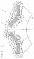
- Fig. 3 is an enlarged view of a relevant part of the rotor core 41. Fig. 3 shows adjacent two magnetic poles.
- a first recess 61 and a second recess 62 that are dented inward are provided on the outer circumference of the rotor core 41 near the flux barrier 41C positioned close to the outer circumference.
- the first recesses 61 are positioned on an outer side in the circumferential direction from the magnetic pole center and the second recesses 62 are positioned on an inner side in the circumferential direction from the magnetic pole center.
- a distance in the circumferential direction between the first recess 61 and the second recess 62 is substantially equal to a distance across the flux barrier 41C in the circumferential direction.
- a line connecting the first recess 61 and the axial center of the rotor core 41 is denoted by L1 and a line connecting the second recess 62 and the axial center of the rotor core 41 is denoted by L2, the flux barrier 41C is provided between the lines L1 and L2.
- a thin portion between the flux barrier 41C and the outer circumference of the rotor core 41 defines the side bridge 44 connecting the first recess 61 and the second recess 62.
- the side bridge 44 has a substantially uniform thickness (i.e., thickness in the radial direction) in the circumferential direction of the rotor core 41 in relation to the opening form of the flux barrier 41C and is formed in a curved arch projecting outward in the radial direction of the rotor core 41.
- the first recess 61 and the second recess 62 are respectively formed on the base ends of the arch-shaped side bridge 44.
- a curvature radius of the side bridge 44 is smaller than a radius of the outer circumference of the rotor core 41.
- a such shaped side bridge 44 stress concentrates by centrifugal force in conjunction with the rotation of the rotor 4, on both the ends and the center of the side bridge 44 in the circumferential direction. Specifically, the stress generates in a dispersed manner on three points of the bottom of each of the first recess 61 and the second recess 62 and an inner surface of the side bridge 44 (flux barrier 41C). Accordingly, the stress does not concentrate on a single point, so that the stress generating in each point can be reduced to improve durability.
- the second recess 62 can serve as a portion for reducing torque pulsation, iron loss, flux harmonic or cogging torque, thereby providing favorable characteristics of the motor 1.
- the supports 71 and 72 respectively projecting toward two of diagonal positions of the permanent magnet 43 are respectively provided to portions forming the flux barriers 41C and 41D in a steel plate 7.
- the support 71 of the flux barrier 41C is in contact with an edge of the first end surface 43B of the permanent magnet 43, the edge being remoter from the outer circumference of the rotor core 41.
- the support 72 of the flux barrier 41 D is provided at an outer base end of the center bridge 45 and is in contact with an edge of the second end surface 43B of the permanent magnet 43, the edge being closer to the outer circumference of the rotor core 41.
- the permanent magnet 43 is supported by the rotor core 41 at two of diagonal positions on the edges of the opposing short sides.
- a contact width of each of the supports 71 and 72 in contact with the end surfaces 43B of the permanent magnet 43 is shorter than a substantially 1/5 (one fifth) of a whole width of the short sides of the permanent magnet 43 on which the end surfaces 43B are provided.
- the contact width shorter than 1/5 of the whole width can reduce the leakage flux from the end surfaces 43B.
- the contact positions of the supports 71 and 72 with the respective end surfaces 43B may be away from the widthwise ends of the end surface 43B (corners of the permanent magnet 43).
- a portion of the steel plate 7 defining the embedding hole 41 B further defines an extended portion 73 at an opposite position from each of the supports 71 and 72 across a corner of the permanent magnet 43.
- the extended portion 73 is provided by extending a part of the embedding hole 41B in order to form a small gap between the steel plate 7 and the lateral surface 43A of the permanent magnet 43.
- the extended portion 73 is provided in all the steel plates 7 to be layered. All the steel plates 7 to be layered have the same shape.
- all the extended portions 73 mutually communicating in the layered direction define a filling hole 48 that penetrates the rotor core 41 in the axial direction.
- the filling hole 48 is provided to the embedding hole 41 B at two of diagonal positions of the permanent magnet 43.
- the filling hole 48 is formed between the permanent magnet 43 and the extended portion 73 while the permanent magnet 43 is inserted in the embedding hole 41 B.
- edges at two diagonal positions of the opposing long sides of the permanent magnet 43 are fixed to the rotor core 41.
- a resin material such as a mold material may be used as the adhesive.
- the permanent magnet 43 is not necessary to apply the adhesive to the entire lateral surfaces 43A of the permanent magnet 43 for fixation, so that time and load for feeding the adhesive can significantly be reduced and an assembly operation can easily be conducted.
- the permanent magnet 43 is fitted in the embedding hole 41B, in which both of the lateral surfaces 43A of the permanent magnet 43 are in contact with the inner surface of the embedding hole 41B. Accordingly, even with a small feed amount of the adhesive, the permanent magnet 43 can securely be held in the embedding hole 41 B.
- the filling hole 48 is formed along the axial direction of the rotor core 41.
- a communication portion that communicates the filling hole 48 with each of the flux barriers 41C and 41D may further be provided. With this arrangement, air in the filling hole 48 can be removed through the communication portion, thereby facilitating feeding the adhesive in the filling hole 48.
- a cross section of the filling hole 48 formed by the extended portion 73 may be enlarged so that a needle for feeding the adhesive can be inserted into the filling hole 48. After such a needle is inserted into the farthest side of the filling hole 48, the adhesive is fed through the needle while the needle is retracted from the farthest side to the near side.
- the adhesive can be fed in a process before the end plates 46 and 47 are provided to the rotor core 41, in other words, in an open state of the ends of the filling hole 48.
- air may be removed through the communication hole when feeding the adhesive by forming on the end plate 46 in advance a communication hole that communicates the filling hole 48 with the outside,.
- the first recess 61 and the second recess 62 are provided on the outer circumference of the rotor core 41.
- the invention encompasses an arrangement in which only the second recess 62 functioning so as to improve characteristics of the motor 1 is provided and the first recess 61 is omitted and an arrangement without the first recess 61 and the second recess 62.
- the invention is applicable to a vehicle such as an electric car, a hybrid car, an electric construction machine and a hybrid construction machine, preferably to a motor for moving the construction machine.
Landscapes
- Engineering & Computer Science (AREA)
- Power Engineering (AREA)
- Permanent Field Magnets Of Synchronous Machinery (AREA)
- Iron Core Of Rotating Electric Machines (AREA)
Applications Claiming Priority (1)
| Application Number | Priority Date | Filing Date | Title |
|---|---|---|---|
| PCT/JP2014/065066 WO2014171558A2 (ja) | 2014-06-06 | 2014-06-06 | 電動機 |
Publications (3)
| Publication Number | Publication Date |
|---|---|
| EP2980962A2 true EP2980962A2 (de) | 2016-02-03 |
| EP2980962A4 EP2980962A4 (de) | 2017-03-01 |
| EP2980962B1 EP2980962B1 (de) | 2020-04-29 |
Family
ID=51731934
Family Applications (1)
| Application Number | Title | Priority Date | Filing Date |
|---|---|---|---|
| EP14785383.2A Active EP2980962B1 (de) | 2014-06-06 | 2014-06-06 | Elektrische maschine |
Country Status (4)
| Country | Link |
|---|---|
| US (1) | US10211688B2 (de) |
| EP (1) | EP2980962B1 (de) |
| CN (1) | CN105379070A (de) |
| WO (1) | WO2014171558A2 (de) |
Cited By (1)
| Publication number | Priority date | Publication date | Assignee | Title |
|---|---|---|---|---|
| EP3297130A1 (de) * | 2016-09-13 | 2018-03-21 | Nanjing Chervon Industry Co., Ltd. | Rotorlaminierungsanordnung |
Families Citing this family (14)
| Publication number | Priority date | Publication date | Assignee | Title |
|---|---|---|---|---|
| EP3192156A4 (de) * | 2014-09-11 | 2018-05-23 | Nissan Motor Co., Ltd | Synchroner permanentmagnetmotor |
| JP2016082696A (ja) * | 2014-10-16 | 2016-05-16 | アイシン精機株式会社 | 埋込磁石型モータおよび埋込磁石型モータのロータ |
| CN109565200B (zh) * | 2016-08-09 | 2021-01-15 | 日本电产株式会社 | 马达 |
| CN106571699A (zh) * | 2016-10-13 | 2017-04-19 | 珠海格力节能环保制冷技术研究中心有限公司 | 驱动电机和电动汽车 |
| CN106787318A (zh) * | 2016-12-28 | 2017-05-31 | 卧龙电气集团股份有限公司 | 永磁同步电机用永磁转子冲片以及永磁同步电机 |
| US11283332B2 (en) * | 2017-07-05 | 2022-03-22 | Mitsubishi Electric Corporation | Rotating electric machine |
| FR3071370B1 (fr) * | 2017-09-18 | 2019-09-13 | IFP Energies Nouvelles | Isthmes de ponts magnetiques d'un rotor de machine electrique |
| US11476733B2 (en) * | 2019-11-01 | 2022-10-18 | GM Global Technology Operations LLC | Electric machine with forced convection-based rotor cooling of rotor magnets |
| EP4068575A4 (de) * | 2019-11-25 | 2023-01-11 | Kabushiki Kaisha Toyota Jidoshokki | Rotor für dynamoelektrische maschine |
| GB2590677B (en) * | 2019-12-23 | 2023-09-27 | Dyson Technology Ltd | A motor core |
| DE102020106341B4 (de) * | 2020-03-09 | 2022-08-04 | Audi Aktiengesellschaft | Elektrische Maschine |
| KR102618055B1 (ko) * | 2021-05-20 | 2023-12-27 | 현대모비스 주식회사 | 로터 조립체 및 이를 포함하는 모터 |
| EP4429078A4 (de) | 2021-11-05 | 2025-06-18 | Kabushiki Kaisha Toshiba | Rotor für elektrische drehmaschine |
| JP7816111B2 (ja) * | 2022-12-07 | 2026-02-18 | トヨタ自動車株式会社 | ロータ |
Family Cites Families (21)
| Publication number | Priority date | Publication date | Assignee | Title |
|---|---|---|---|---|
| JP4005988B2 (ja) | 2004-07-15 | 2007-11-14 | 三菱電機株式会社 | 回転電機の回転子 |
| JP4867194B2 (ja) | 2005-04-28 | 2012-02-01 | トヨタ自動車株式会社 | ロータ |
| JP4660406B2 (ja) * | 2005-09-07 | 2011-03-30 | 株式会社東芝 | 回転電機 |
| US7705503B2 (en) * | 2005-09-07 | 2010-04-27 | Kabushiki Kaisha Toshiba | Rotating electrical machine |
| US8080908B2 (en) | 2005-11-09 | 2011-12-20 | Kabushiki Kaisha Toshiba | Cooling structure for rotor core in electric rotating machine |
| JP4131276B2 (ja) | 2005-12-19 | 2008-08-13 | ダイキン工業株式会社 | 電動機並びにその回転子及び回転子用磁心 |
| JP4842670B2 (ja) | 2006-02-27 | 2011-12-21 | トヨタ自動車株式会社 | ロータおよび電動車両 |
| WO2008137709A2 (en) * | 2007-05-04 | 2008-11-13 | A. O. Smith Corporation | Interior permanent magnet motor and rotor |
| JP5373370B2 (ja) | 2007-11-28 | 2013-12-18 | アスモ株式会社 | 埋込磁石型モータ |
| US7800272B2 (en) | 2007-11-28 | 2010-09-21 | Asmo Co., Ltd. | Embedded magnet motor and manufacturing method of the same |
| JP2009171785A (ja) * | 2008-01-18 | 2009-07-30 | Toyota Motor Corp | 回転電機 |
| JP5452892B2 (ja) | 2008-06-17 | 2014-03-26 | 本田技研工業株式会社 | 永久磁石電動機 |
| JP5443778B2 (ja) | 2009-01-30 | 2014-03-19 | 東芝産業機器製造株式会社 | 永久磁石式回転電機の回転子及びその回転電機 |
| JP5542423B2 (ja) * | 2009-12-22 | 2014-07-09 | 東芝産業機器システム株式会社 | 回転電機の回転子、および回転電機 |
| US9154005B2 (en) | 2010-06-14 | 2015-10-06 | Toyota Jidosha Kabushiki Kaisha | Rotor core for rotating electrical machine, and manufacturing method thereof |
| JP2012186889A (ja) | 2011-03-03 | 2012-09-27 | Nippon Soken Inc | 回転電機 |
| US8674574B2 (en) * | 2011-03-30 | 2014-03-18 | GM Global Technology Operations LLC | Rotor assembly with cooling mechanism |
| JP2013017297A (ja) | 2011-07-04 | 2013-01-24 | Toyota Motor Corp | 回転電機のロータ |
| JP2013021811A (ja) * | 2011-07-11 | 2013-01-31 | Toyota Motor Corp | 回転電機のロータ |
| KR20130019088A (ko) | 2011-08-16 | 2013-02-26 | 엘지이노텍 주식회사 | 모터의 적층 로터 코어 |
| JP2014064471A (ja) * | 2014-01-17 | 2014-04-10 | Nippon Soken Inc | 回転電機 |
-
2014
- 2014-06-06 WO PCT/JP2014/065066 patent/WO2014171558A2/ja not_active Ceased
- 2014-06-06 CN CN201480021841.9A patent/CN105379070A/zh active Pending
- 2014-06-06 US US14/889,969 patent/US10211688B2/en not_active Expired - Fee Related
- 2014-06-06 EP EP14785383.2A patent/EP2980962B1/de active Active
Cited By (2)
| Publication number | Priority date | Publication date | Assignee | Title |
|---|---|---|---|---|
| EP3297130A1 (de) * | 2016-09-13 | 2018-03-21 | Nanjing Chervon Industry Co., Ltd. | Rotorlaminierungsanordnung |
| US11165295B2 (en) | 2016-09-13 | 2021-11-02 | Nanjing Chervon Industry Co., Ltd. | Rotor lamination assembly for a motor |
Also Published As
| Publication number | Publication date |
|---|---|
| WO2014171558A3 (ja) | 2014-12-11 |
| EP2980962A4 (de) | 2017-03-01 |
| US10211688B2 (en) | 2019-02-19 |
| EP2980962B1 (de) | 2020-04-29 |
| US20160301268A1 (en) | 2016-10-13 |
| CN105379070A (zh) | 2016-03-02 |
| WO2014171558A2 (ja) | 2014-10-23 |
Similar Documents
| Publication | Publication Date | Title |
|---|---|---|
| EP2980962B1 (de) | Elektrische maschine | |
| US11283332B2 (en) | Rotating electric machine | |
| EP3468005B1 (de) | Rotor einer elektrischen drehmaschine und verfahren zur herstellung dafür | |
| US10116178B2 (en) | Rotor with embedded permanent magnet having adhesive on one side and cooling channels on the other side | |
| EP2722968B1 (de) | Rotor für elektrische drehmaschine, elektrische drehmaschine und verfahren zur herstellung eines rotors für eine elektrische drehmaschine | |
| US20140084731A1 (en) | Permanent magnet type electric rotating machine and manufacturing method thereof | |
| US10199891B2 (en) | Rotor having end plates and molding flash | |
| US20120200186A1 (en) | Rotor for electric rotating machine | |
| CN107534361B (zh) | 旋转电机 | |
| KR101984411B1 (ko) | 회전 전기 기기 로터 | |
| US20130221772A1 (en) | Cooling structure of rotor for rotary electric machine, and rotary electric machine | |
| JP6133657B2 (ja) | 電動機 | |
| CN107370264B (zh) | 旋转电机的转子的制造方法 | |
| JP2012165480A (ja) | 回転電機用回転子、および、その製造方法 | |
| JP2015053757A (ja) | 電動機、ロータコア、および積層鋼板 | |
| KR20170007166A (ko) | 회전 전기기기 로터의 제조 방법 | |
| JP2017046545A (ja) | 回転電機用ロータ | |
| JP6336711B2 (ja) | 電動機 | |
| EP2955816A1 (de) | Elektrische drehmaschine mit eingebettetem permanentmagnet | |
| US20140132094A1 (en) | Thermal management of an ipm motor with non-magnetic bars | |
| US20190181708A1 (en) | Rotary electrical machine | |
| CN111463937A (zh) | 旋转电机的转子及旋转电机 | |
| JP6424615B2 (ja) | ロータ及びその製造方法、並びにそれを備えた回転電気機械 | |
| JP2015216786A (ja) | 永久磁石埋め込み式回転電機 | |
| JP2016158365A (ja) | モータ |
Legal Events
| Date | Code | Title | Description |
|---|---|---|---|
| PUAI | Public reference made under article 153(3) epc to a published international application that has entered the european phase |
Free format text: ORIGINAL CODE: 0009012 |
|
| 17P | Request for examination filed |
Effective date: 20151028 |
|
| AK | Designated contracting states |
Kind code of ref document: A2 Designated state(s): AL AT BE BG CH CY CZ DE DK EE ES FI FR GB GR HR HU IE IS IT LI LT LU LV MC MK MT NL NO PL PT RO RS SE SI SK SM TR |
|
| AX | Request for extension of the european patent |
Extension state: BA ME |
|
| A4 | Supplementary search report drawn up and despatched |
Effective date: 20170130 |
|
| RIC1 | Information provided on ipc code assigned before grant |
Ipc: H02K 1/27 20060101AFI20170124BHEP Ipc: H02K 1/32 20060101ALN20170124BHEP Ipc: H02K 9/19 20060101ALN20170124BHEP Ipc: H02K 5/20 20060101ALN20170124BHEP |
|
| DAX | Request for extension of the european patent (deleted) | ||
| STAA | Information on the status of an ep patent application or granted ep patent |
Free format text: STATUS: EXAMINATION IS IN PROGRESS |
|
| 17Q | First examination report despatched |
Effective date: 20171109 |
|
| GRAP | Despatch of communication of intention to grant a patent |
Free format text: ORIGINAL CODE: EPIDOSNIGR1 |
|
| STAA | Information on the status of an ep patent application or granted ep patent |
Free format text: STATUS: GRANT OF PATENT IS INTENDED |
|
| RIC1 | Information provided on ipc code assigned before grant |
Ipc: H02K 1/27 20060101AFI20200107BHEP Ipc: H02K 5/20 20060101ALN20200107BHEP Ipc: H02K 1/32 20060101ALN20200107BHEP Ipc: H02K 9/19 20060101ALN20200107BHEP |
|
| INTG | Intention to grant announced |
Effective date: 20200206 |
|
| RIC1 | Information provided on ipc code assigned before grant |
Ipc: H02K 5/20 20060101ALN20200129BHEP Ipc: H02K 1/32 20060101ALN20200129BHEP Ipc: H02K 1/27 20060101AFI20200129BHEP Ipc: H02K 9/19 20060101ALN20200129BHEP |
|
| GRAS | Grant fee paid |
Free format text: ORIGINAL CODE: EPIDOSNIGR3 |
|
| GRAA | (expected) grant |
Free format text: ORIGINAL CODE: 0009210 |
|
| STAA | Information on the status of an ep patent application or granted ep patent |
Free format text: STATUS: THE PATENT HAS BEEN GRANTED |
|
| AK | Designated contracting states |
Kind code of ref document: B1 Designated state(s): AL AT BE BG CH CY CZ DE DK EE ES FI FR GB GR HR HU IE IS IT LI LT LU LV MC MK MT NL NO PL PT RO RS SE SI SK SM TR |
|
| REG | Reference to a national code |
Ref country code: GB Ref legal event code: FG4D |
|
| REG | Reference to a national code |
Ref country code: CH Ref legal event code: EP |
|
| REG | Reference to a national code |
Ref country code: AT Ref legal event code: REF Ref document number: 1264771 Country of ref document: AT Kind code of ref document: T Effective date: 20200515 |
|
| REG | Reference to a national code |
Ref country code: DE Ref legal event code: R096 Ref document number: 602014064577 Country of ref document: DE |
|
| REG | Reference to a national code |
Ref country code: IE Ref legal event code: FG4D |
|
| REG | Reference to a national code |
Ref country code: SE Ref legal event code: TRGR |
|
| REG | Reference to a national code |
Ref country code: NL Ref legal event code: MP Effective date: 20200429 |
|
| REG | Reference to a national code |
Ref country code: LT Ref legal event code: MG4D |
|
| PG25 | Lapsed in a contracting state [announced via postgrant information from national office to epo] |
Ref country code: IS Free format text: LAPSE BECAUSE OF FAILURE TO SUBMIT A TRANSLATION OF THE DESCRIPTION OR TO PAY THE FEE WITHIN THE PRESCRIBED TIME-LIMIT Effective date: 20200829 Ref country code: FI Free format text: LAPSE BECAUSE OF FAILURE TO SUBMIT A TRANSLATION OF THE DESCRIPTION OR TO PAY THE FEE WITHIN THE PRESCRIBED TIME-LIMIT Effective date: 20200429 Ref country code: NO Free format text: LAPSE BECAUSE OF FAILURE TO SUBMIT A TRANSLATION OF THE DESCRIPTION OR TO PAY THE FEE WITHIN THE PRESCRIBED TIME-LIMIT Effective date: 20200729 Ref country code: PT Free format text: LAPSE BECAUSE OF FAILURE TO SUBMIT A TRANSLATION OF THE DESCRIPTION OR TO PAY THE FEE WITHIN THE PRESCRIBED TIME-LIMIT Effective date: 20200831 Ref country code: LT Free format text: LAPSE BECAUSE OF FAILURE TO SUBMIT A TRANSLATION OF THE DESCRIPTION OR TO PAY THE FEE WITHIN THE PRESCRIBED TIME-LIMIT Effective date: 20200429 Ref country code: GR Free format text: LAPSE BECAUSE OF FAILURE TO SUBMIT A TRANSLATION OF THE DESCRIPTION OR TO PAY THE FEE WITHIN THE PRESCRIBED TIME-LIMIT Effective date: 20200730 |
|
| REG | Reference to a national code |
Ref country code: AT Ref legal event code: MK05 Ref document number: 1264771 Country of ref document: AT Kind code of ref document: T Effective date: 20200429 |
|
| PG25 | Lapsed in a contracting state [announced via postgrant information from national office to epo] |
Ref country code: BG Free format text: LAPSE BECAUSE OF FAILURE TO SUBMIT A TRANSLATION OF THE DESCRIPTION OR TO PAY THE FEE WITHIN THE PRESCRIBED TIME-LIMIT Effective date: 20200729 Ref country code: HR Free format text: LAPSE BECAUSE OF FAILURE TO SUBMIT A TRANSLATION OF THE DESCRIPTION OR TO PAY THE FEE WITHIN THE PRESCRIBED TIME-LIMIT Effective date: 20200429 Ref country code: LV Free format text: LAPSE BECAUSE OF FAILURE TO SUBMIT A TRANSLATION OF THE DESCRIPTION OR TO PAY THE FEE WITHIN THE PRESCRIBED TIME-LIMIT Effective date: 20200429 Ref country code: RS Free format text: LAPSE BECAUSE OF FAILURE TO SUBMIT A TRANSLATION OF THE DESCRIPTION OR TO PAY THE FEE WITHIN THE PRESCRIBED TIME-LIMIT Effective date: 20200429 |
|
| PG25 | Lapsed in a contracting state [announced via postgrant information from national office to epo] |
Ref country code: AL Free format text: LAPSE BECAUSE OF FAILURE TO SUBMIT A TRANSLATION OF THE DESCRIPTION OR TO PAY THE FEE WITHIN THE PRESCRIBED TIME-LIMIT Effective date: 20200429 Ref country code: NL Free format text: LAPSE BECAUSE OF FAILURE TO SUBMIT A TRANSLATION OF THE DESCRIPTION OR TO PAY THE FEE WITHIN THE PRESCRIBED TIME-LIMIT Effective date: 20200429 |
|
| PG25 | Lapsed in a contracting state [announced via postgrant information from national office to epo] |
Ref country code: AT Free format text: LAPSE BECAUSE OF FAILURE TO SUBMIT A TRANSLATION OF THE DESCRIPTION OR TO PAY THE FEE WITHIN THE PRESCRIBED TIME-LIMIT Effective date: 20200429 Ref country code: DK Free format text: LAPSE BECAUSE OF FAILURE TO SUBMIT A TRANSLATION OF THE DESCRIPTION OR TO PAY THE FEE WITHIN THE PRESCRIBED TIME-LIMIT Effective date: 20200429 Ref country code: ES Free format text: LAPSE BECAUSE OF FAILURE TO SUBMIT A TRANSLATION OF THE DESCRIPTION OR TO PAY THE FEE WITHIN THE PRESCRIBED TIME-LIMIT Effective date: 20200429 Ref country code: MC Free format text: LAPSE BECAUSE OF FAILURE TO SUBMIT A TRANSLATION OF THE DESCRIPTION OR TO PAY THE FEE WITHIN THE PRESCRIBED TIME-LIMIT Effective date: 20200429 Ref country code: RO Free format text: LAPSE BECAUSE OF FAILURE TO SUBMIT A TRANSLATION OF THE DESCRIPTION OR TO PAY THE FEE WITHIN THE PRESCRIBED TIME-LIMIT Effective date: 20200429 Ref country code: CZ Free format text: LAPSE BECAUSE OF FAILURE TO SUBMIT A TRANSLATION OF THE DESCRIPTION OR TO PAY THE FEE WITHIN THE PRESCRIBED TIME-LIMIT Effective date: 20200429 Ref country code: IT Free format text: LAPSE BECAUSE OF FAILURE TO SUBMIT A TRANSLATION OF THE DESCRIPTION OR TO PAY THE FEE WITHIN THE PRESCRIBED TIME-LIMIT Effective date: 20200429 Ref country code: SM Free format text: LAPSE BECAUSE OF FAILURE TO SUBMIT A TRANSLATION OF THE DESCRIPTION OR TO PAY THE FEE WITHIN THE PRESCRIBED TIME-LIMIT Effective date: 20200429 Ref country code: EE Free format text: LAPSE BECAUSE OF FAILURE TO SUBMIT A TRANSLATION OF THE DESCRIPTION OR TO PAY THE FEE WITHIN THE PRESCRIBED TIME-LIMIT Effective date: 20200429 |
|
| REG | Reference to a national code |
Ref country code: CH Ref legal event code: PL |
|
| REG | Reference to a national code |
Ref country code: DE Ref legal event code: R097 Ref document number: 602014064577 Country of ref document: DE |
|
| PG25 | Lapsed in a contracting state [announced via postgrant information from national office to epo] |
Ref country code: PL Free format text: LAPSE BECAUSE OF FAILURE TO SUBMIT A TRANSLATION OF THE DESCRIPTION OR TO PAY THE FEE WITHIN THE PRESCRIBED TIME-LIMIT Effective date: 20200429 Ref country code: SK Free format text: LAPSE BECAUSE OF FAILURE TO SUBMIT A TRANSLATION OF THE DESCRIPTION OR TO PAY THE FEE WITHIN THE PRESCRIBED TIME-LIMIT Effective date: 20200429 |
|
| PLBE | No opposition filed within time limit |
Free format text: ORIGINAL CODE: 0009261 |
|
| STAA | Information on the status of an ep patent application or granted ep patent |
Free format text: STATUS: NO OPPOSITION FILED WITHIN TIME LIMIT |
|
| GBPC | Gb: european patent ceased through non-payment of renewal fee |
Effective date: 20200729 |
|
| PG25 | Lapsed in a contracting state [announced via postgrant information from national office to epo] |
Ref country code: LU Free format text: LAPSE BECAUSE OF NON-PAYMENT OF DUE FEES Effective date: 20200606 |
|
| 26N | No opposition filed |
Effective date: 20210201 |
|
| REG | Reference to a national code |
Ref country code: BE Ref legal event code: MM Effective date: 20200630 |
|
| PG25 | Lapsed in a contracting state [announced via postgrant information from national office to epo] |
Ref country code: FR Free format text: LAPSE BECAUSE OF NON-PAYMENT OF DUE FEES Effective date: 20200629 Ref country code: GB Free format text: LAPSE BECAUSE OF NON-PAYMENT OF DUE FEES Effective date: 20200729 Ref country code: LI Free format text: LAPSE BECAUSE OF NON-PAYMENT OF DUE FEES Effective date: 20200630 Ref country code: IE Free format text: LAPSE BECAUSE OF NON-PAYMENT OF DUE FEES Effective date: 20200606 Ref country code: CH Free format text: LAPSE BECAUSE OF NON-PAYMENT OF DUE FEES Effective date: 20200630 |
|
| PG25 | Lapsed in a contracting state [announced via postgrant information from national office to epo] |
Ref country code: BE Free format text: LAPSE BECAUSE OF NON-PAYMENT OF DUE FEES Effective date: 20200630 Ref country code: SI Free format text: LAPSE BECAUSE OF FAILURE TO SUBMIT A TRANSLATION OF THE DESCRIPTION OR TO PAY THE FEE WITHIN THE PRESCRIBED TIME-LIMIT Effective date: 20200429 |
|
| PGFP | Annual fee paid to national office [announced via postgrant information from national office to epo] |
Ref country code: DE Payment date: 20210511 Year of fee payment: 8 |
|
| PGFP | Annual fee paid to national office [announced via postgrant information from national office to epo] |
Ref country code: SE Payment date: 20210610 Year of fee payment: 8 |
|
| PG25 | Lapsed in a contracting state [announced via postgrant information from national office to epo] |
Ref country code: TR Free format text: LAPSE BECAUSE OF FAILURE TO SUBMIT A TRANSLATION OF THE DESCRIPTION OR TO PAY THE FEE WITHIN THE PRESCRIBED TIME-LIMIT Effective date: 20200429 Ref country code: MT Free format text: LAPSE BECAUSE OF FAILURE TO SUBMIT A TRANSLATION OF THE DESCRIPTION OR TO PAY THE FEE WITHIN THE PRESCRIBED TIME-LIMIT Effective date: 20200429 Ref country code: CY Free format text: LAPSE BECAUSE OF FAILURE TO SUBMIT A TRANSLATION OF THE DESCRIPTION OR TO PAY THE FEE WITHIN THE PRESCRIBED TIME-LIMIT Effective date: 20200429 |
|
| PG25 | Lapsed in a contracting state [announced via postgrant information from national office to epo] |
Ref country code: MK Free format text: LAPSE BECAUSE OF FAILURE TO SUBMIT A TRANSLATION OF THE DESCRIPTION OR TO PAY THE FEE WITHIN THE PRESCRIBED TIME-LIMIT Effective date: 20200429 |
|
| REG | Reference to a national code |
Ref country code: DE Ref legal event code: R119 Ref document number: 602014064577 Country of ref document: DE |
|
| REG | Reference to a national code |
Ref country code: SE Ref legal event code: EUG |
|
| PG25 | Lapsed in a contracting state [announced via postgrant information from national office to epo] |
Ref country code: SE Free format text: LAPSE BECAUSE OF NON-PAYMENT OF DUE FEES Effective date: 20220607 |
|
| PG25 | Lapsed in a contracting state [announced via postgrant information from national office to epo] |
Ref country code: DE Free format text: LAPSE BECAUSE OF NON-PAYMENT OF DUE FEES Effective date: 20230103 |