EP2980969A1 - Synchron-reluktanzmotor und rotor für synchron-reluktanzmotor - Google Patents
Synchron-reluktanzmotor und rotor für synchron-reluktanzmotor Download PDFInfo
- Publication number
- EP2980969A1 EP2980969A1 EP14773170.7A EP14773170A EP2980969A1 EP 2980969 A1 EP2980969 A1 EP 2980969A1 EP 14773170 A EP14773170 A EP 14773170A EP 2980969 A1 EP2980969 A1 EP 2980969A1
- Authority
- EP
- European Patent Office
- Prior art keywords
- flux barriers
- axis
- reluctance motor
- synchronous reluctance
- rotor
- Prior art date
- Legal status (The legal status is an assumption and is not a legal conclusion. Google has not performed a legal analysis and makes no representation as to the accuracy of the status listed.)
- Granted
Links
Images




Classifications
-
- H—ELECTRICITY
- H02—GENERATION; CONVERSION OR DISTRIBUTION OF ELECTRIC POWER
- H02K—DYNAMO-ELECTRIC MACHINES
- H02K1/00—Details of the magnetic circuit
- H02K1/06—Details of the magnetic circuit characterised by the shape, form or construction
- H02K1/22—Rotating parts of the magnetic circuit
- H02K1/24—Rotor cores with salient poles ; Variable reluctance rotors
- H02K1/246—Variable reluctance rotors
-
- H—ELECTRICITY
- H02—GENERATION; CONVERSION OR DISTRIBUTION OF ELECTRIC POWER
- H02K—DYNAMO-ELECTRIC MACHINES
- H02K1/00—Details of the magnetic circuit
- H02K1/06—Details of the magnetic circuit characterised by the shape, form or construction
- H02K1/22—Rotating parts of the magnetic circuit
- H02K1/27—Rotor cores with permanent magnets
- H02K1/2706—Inner rotors
-
- H—ELECTRICITY
- H02—GENERATION; CONVERSION OR DISTRIBUTION OF ELECTRIC POWER
- H02K—DYNAMO-ELECTRIC MACHINES
- H02K1/00—Details of the magnetic circuit
- H02K1/06—Details of the magnetic circuit characterised by the shape, form or construction
- H02K1/22—Rotating parts of the magnetic circuit
- H02K1/28—Means for mounting or fastening rotating magnetic parts on to, or to, the rotor structures
-
- H—ELECTRICITY
- H02—GENERATION; CONVERSION OR DISTRIBUTION OF ELECTRIC POWER
- H02K—DYNAMO-ELECTRIC MACHINES
- H02K19/00—Synchronous motors or generators
- H02K19/02—Synchronous motors
- H02K19/10—Synchronous motors for multi-phase current
-
- H—ELECTRICITY
- H02—GENERATION; CONVERSION OR DISTRIBUTION OF ELECTRIC POWER
- H02K—DYNAMO-ELECTRIC MACHINES
- H02K19/00—Synchronous motors or generators
- H02K19/02—Synchronous motors
- H02K19/10—Synchronous motors for multi-phase current
- H02K19/103—Motors having windings on the stator and a variable reluctance soft-iron rotor without windings
Definitions
- the present invention relates to a synchronous reluctance motor and a rotor therefor.
- CMOS permanent magnet synchronous electric motor
- FCSM Field Coil Synchronous Motor
- RM reluctance motor
- a PMSM has no power loss in magnetic creation and is high in efficiency.
- field-weakening control needs to be performed at the time of high-speed rotation.
- An RM or a motor without any permanent magnet, has gained attention because of the problems associated with the PMSMs and a surge in the prices of magnets.
- a synchronous reluctance motor (SynRM), which rotates in synchronization with a sine wave rotating field
- SRM switched reluctance motor
- the SynRM is known to be lower in noise and vibration than the SRM.
- a rotor of the SynRM the direction of a main magnetic flux is referred to as q-axis, and a direction that is electrically and magnetically orthogonal to that direction is referred to as d-axis.
- the rotor of the SynRM has, for example, five layers of flux barriers (slits) within a region between two q-axes whose electrical angles are, for example, n (180 degrees) apart each other.
- the d-axis direction inductance of the rotor, or d-axis inductance Ld is smaller than q-axis direction inductance, or q-axis inductance Lq.
- Id is a current that creates a d-axis direction magnetic flux
- Iq is a current that creates a q-axis direction magnetic flux.
- concave grooves are provided near a d-axis on an outer peripheral surface of a rotor core, and a rotor coil is wound around the concave grooves.
- the torque is generated by current flux ⁇ i in addition to the reluctance torque.
- the concave grooves are provided near the d-axis, which is defined as described above. Therefore, it is possible to prevent a decrease in the reluctance torque. As a result, it is possible to improve the torque and the efficiency.
- the width of a magnetic path on the side of an upper layer (or in a radial-direction outer-side portion perpendicular to the axis of the rotor) of multi-layered magnetic paths is relatively narrow. Accordingly, the problem is that a large magnetic resistance occurs locally, leading to a decrease in the q-axis inductance (Lq) of the entire rotor and resulting in a drop in the torque and the power factor.
- Lq q-axis inductance
- the present invention has been made to solve the above problems.
- the object of the present invention is to raise the salient pole ratio (Lq / Ld) of the synchronous reluctance motor and increase the torque and power factor.
- a synchronous reluctance motor comprising: a rotor shaft which is supported in a rotatable manner and axially extends at a rotation axis; a rotor core on which a plurality of flux barriers are formed and which is fixed to the rotor shaft and extends in the direction of the rotation axis; a stator core which is disposed on an outer periphery of the rotor core in such a way as to form a gap between the rotor core and the stator core and on which a plurality of protruding stator teeth are formed in such a way as to be spaced out in a circumferential direction each other and extend in the direction of the rotation-axis; and multiphase armature windings of a plurality of poles which are wound around the plurality of stator teeth, wherein the flux barriers include a plurality of first flux barriers which are formed in such a way as to be spaced out in the circumferential direction each other and extend in the direction of the rotation-axis;
- a rotor of a synchronous reluctance motor equipped with a stator core including an armature winding comprising: a rotor shaft which is supported in a rotatable manner and axially extends at a rotation axis; and a rotor core on which a plurality of flux barriers are formed and which is fixed to the rotor shaft and extends in the direction of the rotation axis, wherein the flux barriers include a plurality of first flux barriers which are formed in such a way as to be spaced out in the circumferential direction each other and extend in a radial direction, and a plurality of second flux barriers which are formed in each of circumferential angular regions sandwiched between the first flux barriers in such a way as to form a curved surface convex toward the rotation-axis center and to spread and be spaced out in the circumferential direction each other.
- FIG. 1 is a cross-sectional view of a synchronous reluctance motor, which is perpendicular to the direction of a rotation axis, according to a first embodiment.
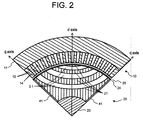
- FIG. 2 is a detailed, partial cross-sectional view of the synchronous reluctance motor, which is perpendicular to the direction of the rotation axis, according to the first embodiment.
- FIG. 2 is a cross-sectional view of one-fourth of the synchronous reluctance motor.
- FIG. 2 is a diagram showing the one-fourth portion only because of ease of explanation. This does not mean that the synchronous reluctance motor can be divided on a one-fourth basis.
- a synchronous reluctance motor 100 includes, in a housing (not shown), a stator 10 and a rotor 20.
- the stator 10 includes a stator core 11 and a plurality of stator teeth 12.
- the stator core 11 has a structure in which electromagnetic steel sheets, which are thin plates produced by adding silicon to iron, in order to reduce an eddy current loss, are stacked in the direction of a rotation axis.
- the stator core 11 is cylindrical in shape, extending in a direction of the rotation-axis of a rotor shaft 23.
- the stator teeth 12 are arranged on an inner periphery of the stator 10 and are mutually spaced out in a circumferential direction.
- the stator teeth 12 extend in the direction of the rotation-axis of the rotor shaft 23.
- Each of the stator teeth 12 protrudes toward a rotation center of the rotor 20 from the side of the stator core 11.
- the tip of each of the stator teeth 12 faces an outer periphery of the rotor 20 across a radial-direction gap 25.
- stator slots 14 are formed in such a way as to extend in the direction of the rotation-axis of the rotor shaft 23.
- FIG. 3 is a wiring diagram of armature windings of the synchronous reluctance motor according to the first embodiment.
- Armature windings 15 are wound around the stator teeth 12 and are housed inside the stator slots 14.
- multiphase armature windings 15, for example, three-phase armature windings 15, of a plurality of poles are wound. Through each armature winding 15, AC current of one of U-phase, v-phase, or W-phase flows.
- the rotor 20 is disposed in such a way as to create space between the rotor 20 and the stator 10. As described above, no field winding is wound around the rotor 20.
- the rotor 20 includes a rotor core 21 and the rotor shaft 23.
- the rotor shaft 23 extends coaxially with the rotation axis.
- the rotor shaft 23 is supported by bearings (not shown), which are provided in the housing, in a rotatable manner.
- the bearings may be rolling bearings such as roller bearings or ball bearings, or sliding bearings.
- the rotor core 21 has a structure in which electromagnetic steel sheets, which are thin plates produced by adding silicon to iron in order to reduce an eddy current loss, are stacked in the direction of the rotation axis.
- the rotor core 21, in which the thin plates are stacked, is cylindrical in shape and occupies around the rotor shaft 23 in such a way as to be thick in the radial direction.
- a bridge portion 24 is provided on an outer peripheral portion of the rotor core 21, in order to keep the mechanical strength of the rotor 20, on an outer peripheral portion of the rotor core 21, a bridge portion 24 is provided.
- first flux barrier and second flux barrier which are magnetic barriers extending in the direction of the rotation-axis, are formed.
- the first flux barriers are a plurality of q-axis direction flux barriers 41, which are formed in such a way as to be spaced out in the circumferential direction each other, and extend in the radial direction.
- the q-axis direction flux barriers 41 are formed in such a way as to pierce through each of electromagnetic steel plates that make up the rotor core 21.
- the q-axis direction flux barriers 41 extend in the radial direction along the q-axis direction.
- each of the steel plates a plurality of penetration portions are formed for the q-axis direction flux barriers 41.
- the second flux barriers are a plurality of d-axis peripheral flux barriers 31 that are provided in each of circumferential-direction angular regions (referred to as circumferential angular regions, hereinafter) sandwiched between adjacent q-axis direction flux barriers 41.
- the d-axis peripheral flux barriers 31 mutually spread in the circumferential direction in each of the circumferential angular regions.
- the d-axis peripheral flux barriers 31 extend toward the rotation axis of the rotor shaft in such a way as to form a convex curved surface. Both ends of the curved surface do not cross the q-axis direction flux barriers 41; the two ends of the curved surface reach the bridge portion 24.
- Adjacent d-axis peripheral flux barriers 31 are spaced out in such a way as not to cross or contact each other.
- the rotor core 21 appears to be completely divided into pieces.
- the adjacent steel-plate portions of the rotor core 21 between which the q-axis direction flux barriers 41 or d-axis peripheral flux barriers 31 are sandwiched are partially connected to each other, thus making it possible to keep the relative positional relations.
- a rotating magnetic field is generated around the rotation axis of the rotor 20.
- the rotor 20 is attracted by the rotating magnetic field and rotating around the rotor shaft 23.
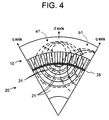
- FIG. 4 is a schematic magnetic flux distribution diagram of a cross section of a conventional synchronous reluctance motor, which is perpendicular to the direction of a rotation axis.
- q-axis direction flux barriers 41 are not provided in the conventional synchronous reluctance motor. That is, FIG. 4 shows a magnetic flux distribution when there are no q-axis direction flux barriers 41.
- the diagram shows the magnetic flux distribution of a one-sixth section of the rotor 20.
- broken line a1 represents q-axis magnetic fluxes, with major magnetic fluxes traveling along q-axis.
- b1 represents d-axis magnetic fluxes, with major magnetic fluxes traveling along d-axis.
- the rotor 20 rotates at the same angular velocity as the stator 10. Therefore, on the rotor 20, the positions of those magnetic fluxes remain unchanged, and the magnetic fluxes stay at the same positions. That is, when viewed from a stationary system, those magnetic fluxes rotate at the same angular velocity as the rotor 20.
- q-axis magnetic fluxes pass through each of portions of the rotor core 21 that are divided by d-axis peripheral flux barriers 31. Moreover, q-axis magnetic fluxes enter the side of the stator 10 after passing through a gap 25 between the stator 10 and the rotor 20.
- the magnetic fluxes within the rotor 20 and the magnetic fluxes passing through the stator 10 form a closed loop as a whole, and form magnetic fluxes traveling along q-axis in the vicinity of q-axis.
- magnetic fluxes b1 are connected to magnetic fluxes in an adjacent one-sixth section, which is not shown in FIG. 4 . As shown in FIG. 4 , magnetic fluxes b1 form magnetic fluxes traveling along the d-axis direction in the vicinity of d-axis.
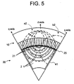
- FIG. 5 is a schematic magnetic flux distribution diagram of a cross section of the synchronous reluctance motor of the first embodiment, which is perpendicular to the direction of the rotation axis. That is, the diagram shows a magnetic flux distribution when the q-axis direction flux barriers 41 are provided.
- broken line a2 represents q-axis magnetic fluxes, with major magnetic fluxes traveling along q-axis.
- b2 represents d-axis magnetic fluxes, with major magnetic fluxes traveling along d-axis.
- the q-axis direction flux barriers 41 exist on paths of d-axis magnetic fluxes.
- the q-axis direction flux barriers 41 are air layers, and are smaller in permeability than the steel-plate portions of the rotor core 21. As a result, the existence of the q-axis direction flux barriers 41 makes it difficult for d-axis magnetic fluxes to pass therethrough.
- the magnetic flux lines are being shown qualitatively. Based on the number of q-axis magnetic flux lines, d-axis magnetic flux lines are shown. Accordingly, it is assumed that the number of magnetic flux lines of q-axis magnetic fluxes shown in FIG. 4 is equal to the number of magnetic flux lines of q-axis magnetic fluxes shown in FIG. 5 .
- the number of magnetic flux lines of d-axis magnetic fluxes b2 in FIG. 5 is smaller than the number of magnetic flux lines of d-axis magnetic fluxes b1 in FIG. 4 . That is, the percentage of d-axis magnetic fluxes relative to q-axis magnetic fluxes in the present embodiment shown in FIG. 5 is smaller than the percentage of d-axis magnetic fluxes relative to q-axis magnetic fluxes in the conventional structure shown in FIG. 4 .
- the conventional SynRM has been configured in such a way as to make the passage of d-axis magnetic fluxes more difficult than that of q-axis magnetic fluxes.
- the q-axis direction flux barriers 41 are provided. Therefore, the d-axis magnetic fluxes face much more difficulty in passing than the q-axis magnetic fluxes.
- FIG. 6 is a comparison diagram of average rotor shaft torque of the conventional synchronous reluctance motor and synchronous reluctance motor of the first embodiment.
- the q-axis direction inductance of the rotor 20, or q-axis inductance is represented by Lq.
- the d-axis direction inductance, or d-axis inductance is represented by Ld.
- the q-axis direction component of current flowing through the rotor core 21 is represented by Iq, and the d-axis direction component by Id.
- the torque of the synchronous reluctance motor of the present embodiment is significantly larger, or about 1% larger, than the torque of the conventional synchronous reluctance motor.
- FIG. 7 is a comparison diagram of the power factors of the conventional synchronous reluctance motor and synchronous reluctance motor of the first embodiment.
- the power factor of the synchronous reluctance motor of the present embodiment is about 2% larger than the power factor of the conventional synchronous reluctance motor. In this manner, the power factor has been significantly improved.
- the salient pole ratio (Lq / Ld) of the synchronous reluctance motor becomes larger. Therefore, it is possible to increase the torque and power factor.
- FIG. 8 is a cross-sectional view of a synchronous reluctance motor of a second embodiment, which is perpendicular to the direction of a rotation axis.
- the present embodiment is a variant of the first embodiment.
- a star-shaped rotor shaft 50 includes four radial plates 51, which extend toward a radial-direction outer side.
- the four radial plates 51 are arranged in such a way as to be spaced out in a circumferential direction and extend in the direction of a rotation axis of the rotor 20. What is shown here is the four radial plates 51. However, the number of radial plates 51 is not limited to four.
- a plurality of radial plates 51 e.g., six radial plates 51, may be provided.
- the radial plates 51 of the second embodiment are disposed in regions corresponding to where the q-axis direction flux barriers 41 are formed in the first embodiment.
- the star-shaped rotor shaft 50 is made of nonmagnetic material. Accordingly, as in the case of the q-axis direction flux barriers 41 of the first embodiment, the radial plates 51 is high in magnetic resistance, and does not allow a magnetic flux to easily pass therethrough.
- each radial plate 51 On both sides of each radial plate 51, dovetail projections are formed in such a way as to extend in the direction of the rotation-axis and protrude in the circumferential direction.
- fitting portions 52 in which grooves are formed in such a way as to fit onto the dovetail projections are provided. Since the radial plates 51 are fitted into the rotor core 21, a positional shift between the radial plates 51 and the rotor core 21 does not occur.
- fitting portions 52 that are dovetail-shaped.
- the fitting portions 52 are not limited to be dovetail-shaped.
- the fitting portions 52 may be rectangular or triangular in shape, for example.
- the sides of the radial plates 51 are convex, and the side of the rotor core 21 is concave. Instead, grooves may be formed on side surfaces of the radial plates 51, and projections may be formed on the side of the rotor core 21.
- the radial plates 51 of the star-shaped rotor shaft 50 act in the same way as the q-axis direction flux barriers of the first embodiment. Therefore, the salient pole ratio (Lq / Ld) becomes larger than that of the conventional synchronous reluctance motor, thereby increasing the torque and power factor.
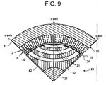
- FIG. 9 is a partial cross-sectional view showing details of a cross section of a synchronous reluctance motor of a third embodiment, which is perpendicular to the direction of a rotation axis.
- the present embodiment is a variant of the first embodiment.
- the d-axis peripheral flux barriers 31 and the q-axis direction flux barriers 41 are air layers.
- d-axis peripheral flux barriers 32 and q-axis direction flux barriers 42 are filled with nonmagnetic-material resin.
- the q-axis direction flux barriers 42 act in the same way as the q-axis direction flux barriers 41 of the first embodiment. Therefore, the salient pole ratio (Lq / Ld) becomes larger, increasing the torque and power factor.
- the d-axis peripheral flux barriers 32 and the q-axis direction flux barriers 42 are both filled with resin. Therefore, it is possible to secure the mechanical strength of the rotor core 21.
- d-axis peripheral flux barriers 32 or the q-axis direction flux barriers 42 may be filled with nonmagnetic-material resin.
- d-axis peripheral flux barriers 32 may be filled with nonmagnetic-material resin.
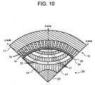
- FIG. 10 is a partial cross-sectional view showing details of a cross section of a synchronous reluctance motor of a fourth embodiment, which is perpendicular to the direction of a rotation axis.
- the present embodiment is a variant of the first embodiment.
- the d-axis peripheral flux barriers 31 and the q-axis direction flux barriers 41 are air layers.
- d-axis peripheral permanent magnets 33 which are permanent magnets, are provided as d-axis peripheral flux barriers.
- the d-axis peripheral flux barriers are permanent magnets 33. Therefore, it is possible to form magnetic barriers, as in the case of the first embodiment.
- the q-axis direction flux barriers 41 are air layers, and act in the same way as in the first embodiment. Therefore, the salient pole ratio (Lq / Ld) becomes larger, increasing the torque and power factor.
- permanent magnets may be provided both in the vicinity of d-axis and in the direction of q-axis; or permanent magnets may be provided only in portions around d-axis.
- each embodiment may be used in combination.
- the star-shaped rotor shaft 51 which is a feature of the second embodiment, may be used in combination with the flux barriers filled with nonmagnetic-material resin, which are a feature of the third embodiment.
- star-shaped rotor shaft 50 which is a feature of the second embodiment, may be used in combination with the installment of permanent magnets, which is a feature of the fourth embodiment.
- stator stator
- 11 stator core
- 12 stator teeth
- 14 stator slots
- 15 armature winding
- 20 rotor
- 21 rotor core
- 23 rotor shaft
- 24 bridge portion
- 25 gap
- 31,32 d-axis peripheral flux barrier
- 33 permanent magnet
- 41,42 q-axis direction flux barrier
- 50 star-shaped rotor shaft
- 51 radial plate
- 52 fitting portion
- 100 synchronous reluctance motor
Landscapes
- Engineering & Computer Science (AREA)
- Power Engineering (AREA)
- Synchronous Machinery (AREA)
Applications Claiming Priority (2)
| Application Number | Priority Date | Filing Date | Title |
|---|---|---|---|
| JP2013069006A JP5969946B2 (ja) | 2013-03-28 | 2013-03-28 | 同期リラクタンスモータ |
| PCT/JP2014/001762 WO2014156158A1 (ja) | 2013-03-28 | 2014-03-27 | 同期リラクタンスモータおよび同期リラクタンスモータの回転子 |
Publications (3)
| Publication Number | Publication Date |
|---|---|
| EP2980969A1 true EP2980969A1 (de) | 2016-02-03 |
| EP2980969A4 EP2980969A4 (de) | 2016-11-30 |
| EP2980969B1 EP2980969B1 (de) | 2021-03-10 |
Family
ID=51623170
Family Applications (1)
| Application Number | Title | Priority Date | Filing Date |
|---|---|---|---|
| EP14773170.7A Not-in-force EP2980969B1 (de) | 2013-03-28 | 2014-03-27 | Synchron-reluktanzmotor und rotor für synchron-reluktanzmotor |
Country Status (6)
| Country | Link |
|---|---|
| US (1) | US9853508B2 (de) |
| EP (1) | EP2980969B1 (de) |
| JP (1) | JP5969946B2 (de) |
| CN (1) | CN105103420B (de) |
| SG (1) | SG11201508007TA (de) |
| WO (1) | WO2014156158A1 (de) |
Families Citing this family (25)
| Publication number | Priority date | Publication date | Assignee | Title |
|---|---|---|---|---|
| JP5969946B2 (ja) * | 2013-03-28 | 2016-08-17 | 東芝三菱電機産業システム株式会社 | 同期リラクタンスモータ |
| US10411532B2 (en) * | 2013-10-27 | 2019-09-10 | Moovee Innovations Inc. | Software-defined electric motor |
| JP6366986B2 (ja) | 2014-04-11 | 2018-08-01 | 株式会社東芝 | 同期リラクタンス型回転電機 |
| WO2016171021A1 (ja) * | 2015-04-24 | 2016-10-27 | 株式会社東芝 | 同期リラクタンスモータ |
| JP6589931B2 (ja) * | 2016-06-03 | 2019-10-16 | 株式会社デンソー | 回転電機駆動システム |
| EP3261238B1 (de) * | 2016-06-23 | 2020-08-12 | Goodrich Actuation Systems Limited | Magnetgetriebe |
| RU2634587C1 (ru) * | 2016-07-26 | 2017-11-01 | Общество с ограниченной ответственностью "ЭМАШ" | Синхронная реактивная машина |
| JP6702550B2 (ja) * | 2016-08-31 | 2020-06-03 | 株式会社東芝 | 回転子およびリラクタンスモータ |
| JP6718797B2 (ja) | 2016-11-11 | 2020-07-08 | 東芝産業機器システム株式会社 | 同期リラクタンス回転電機 |
| US11515771B2 (en) | 2017-03-28 | 2022-11-29 | Enedym Inc. | Alternating-current driven, salient-teeth reluctance motor with concentrated windings |
| US11843334B2 (en) | 2017-07-13 | 2023-12-12 | Denso Corporation | Rotating electrical machine |
| CN113972806B (zh) | 2017-07-21 | 2023-10-31 | 株式会社电装 | 旋转电机 |
| US11658522B2 (en) * | 2017-10-13 | 2023-05-23 | Ford Global Technologies, Llc | Electric machine having magnetically modified region |
| CN108110920A (zh) | 2017-12-14 | 2018-06-01 | 珠海格力节能环保制冷技术研究中心有限公司 | 异步起动同步磁阻电机转子、电机及压缩机 |
| DE112018006699T5 (de) | 2017-12-28 | 2020-09-10 | Denso Corporation | Rotierende elektrische Maschine |
| JP7006541B2 (ja) | 2017-12-28 | 2022-01-24 | 株式会社デンソー | 回転電機 |
| CN111566904B (zh) | 2017-12-28 | 2023-04-28 | 株式会社电装 | 旋转电机 |
| JP6939750B2 (ja) | 2017-12-28 | 2021-09-22 | 株式会社デンソー | 回転電機 |
| DE112018006694T5 (de) | 2017-12-28 | 2020-09-10 | Denso Corporation | Rotierende elektrische Maschine |
| DE112020006839T5 (de) | 2020-03-05 | 2022-12-15 | Denso Corporation | Rotierende elektrische Maschinen |
| IT202000006052A1 (it) * | 2020-03-23 | 2021-09-23 | Motovario S P A | Motore a riluttanza autoavviante. |
| US11909264B2 (en) * | 2020-07-14 | 2024-02-20 | Board Of Regents, The University Of Texas System | Rotor configuration for switched reluctance motor with minimized torque ripple |
| WO2023166550A1 (ja) * | 2022-03-01 | 2023-09-07 | 三菱電機株式会社 | 同期リラクタンスモータの回転子 |
| CN120283346A (zh) * | 2022-11-30 | 2025-07-08 | Ifp新能源公司 | 用于电机的包括至少两个具有凹形中心线的磁通屏障的转子 |
| FR3142621A1 (fr) * | 2022-11-30 | 2024-05-31 | IFP Energies Nouvelles | Rotor pour machine électrique comprenant au moins deux barrières de flux avec des lignes médianes concaves |
Family Cites Families (21)
| Publication number | Priority date | Publication date | Assignee | Title |
|---|---|---|---|---|
| US2913607A (en) * | 1957-01-16 | 1959-11-17 | Allis Louis Co | Synchronous induction motor |
| GB1347561A (en) * | 1970-01-30 | 1974-02-27 | Nat Res Dev | Dynamo-electric machines of the reluctance type |
| JPH0666277U (ja) * | 1993-02-19 | 1994-09-16 | 株式会社安川電機 | 永久磁石形同期電動機のロータ |
| US6300703B1 (en) * | 1997-03-13 | 2001-10-09 | Matsushita Electric Industrial Co., Ltd. | Rotor core for reluctance motor |
| JP2000197325A (ja) | 1998-12-25 | 2000-07-14 | Matsushita Electric Ind Co Ltd | リラクタンスモ―タ |
| JP4058576B2 (ja) * | 1999-03-30 | 2008-03-12 | 株式会社富士通ゼネラル | リラクタンスモータ |
| WO2002031947A1 (en) * | 2000-10-12 | 2002-04-18 | Matsushita Electric Industrial Co., Ltd. | Electric motor |
| JP2005341655A (ja) | 2004-05-24 | 2005-12-08 | Denso Corp | 磁石埋め込み式回転電機のロータ |
| JP2006121821A (ja) | 2004-10-21 | 2006-05-11 | Honda Motor Co Ltd | シンクロナスリラクタンスモータおよびシンクロナスリラクタンスモータを搭載した電動ステアリング装置 |
| JP5221895B2 (ja) * | 2007-05-10 | 2013-06-26 | 本田技研工業株式会社 | シンクロナスリラクタンスモータ |
| JP2009194945A (ja) | 2008-02-12 | 2009-08-27 | Denso Corp | シンクロナスリラクタンスモータ |
| KR101021120B1 (ko) | 2009-07-14 | 2011-03-14 | 한양대학교 산학협력단 | 고속모터용 회전자 |
| FR2948508B1 (fr) * | 2009-07-22 | 2012-11-23 | Michelin Soc Tech | Procede pour la fabrication d'un rotor interieur pour machine electrique tournante. |
| WO2011120564A1 (en) | 2010-03-30 | 2011-10-06 | Abb Research Ltd | Rotor disc, rotor assembly, synchronous machine, and method of producing thereof |
| CN102244429B (zh) * | 2010-05-13 | 2014-09-03 | 株式会社电装 | 转子铁心以及转子铁心与旋转轴的紧固方法 |
| CN102986123A (zh) * | 2010-07-02 | 2013-03-20 | Abb研究有限公司 | 具有轮辐开口的转子盘 |
| FR2976139B1 (fr) * | 2011-05-31 | 2016-04-15 | Moteurs Leroy-Somer | Rotor a aimants permanents et machine tournante comportant un tel rotor. |
| JP2013021840A (ja) | 2011-07-12 | 2013-01-31 | Honda Motor Co Ltd | リラクタンスモータのロータ |
| DE102013201353A1 (de) * | 2012-02-10 | 2013-08-14 | Ksb Aktiengesellschaft | Rotor und Reluktanzmotor |
| CN102801236A (zh) * | 2012-03-05 | 2012-11-28 | 珠海格力节能环保制冷技术研究中心有限公司 | 永磁辅助同步磁阻电机及其转子以及该电机的组装方法 |
| JP5969946B2 (ja) * | 2013-03-28 | 2016-08-17 | 東芝三菱電機産業システム株式会社 | 同期リラクタンスモータ |
-
2013
- 2013-03-28 JP JP2013069006A patent/JP5969946B2/ja active Active
-
2014
- 2014-03-27 EP EP14773170.7A patent/EP2980969B1/de not_active Not-in-force
- 2014-03-27 US US14/779,263 patent/US9853508B2/en not_active Expired - Fee Related
- 2014-03-27 SG SG11201508007TA patent/SG11201508007TA/en unknown
- 2014-03-27 WO PCT/JP2014/001762 patent/WO2014156158A1/ja not_active Ceased
- 2014-03-27 CN CN201480018261.4A patent/CN105103420B/zh not_active Expired - Fee Related
Also Published As
| Publication number | Publication date |
|---|---|
| US20160049835A1 (en) | 2016-02-18 |
| EP2980969B1 (de) | 2021-03-10 |
| JP5969946B2 (ja) | 2016-08-17 |
| EP2980969A4 (de) | 2016-11-30 |
| CN105103420B (zh) | 2018-01-02 |
| JP2014193076A (ja) | 2014-10-06 |
| CN105103420A (zh) | 2015-11-25 |
| WO2014156158A1 (ja) | 2014-10-02 |
| SG11201508007TA (en) | 2015-11-27 |
| US9853508B2 (en) | 2017-12-26 |
Similar Documents
| Publication | Publication Date | Title |
|---|---|---|
| US9853508B2 (en) | Synchronous reluctance motor and rotor for synchronous reluctance motor | |
| EP3457534B1 (de) | Rotierende elektrische maschine | |
| JP5866074B1 (ja) | シンクロナスリラクタンスモータ | |
| EP3534496B1 (de) | Dauermagnetmotor | |
| JP4900132B2 (ja) | 回転子及び回転電機 | |
| US10749385B2 (en) | Dual magnetic phase material rings for AC electric machines | |
| US8760026B2 (en) | Rotor with V-shaped permanent magnet arrangement, rotating electric machine, vehicle, elevator, fluid machine, and processing machine | |
| CN104508948A (zh) | 磁铁辅助型磁阻马达用转子和无刷马达 | |
| CN103339832A (zh) | 车辆用永磁铁埋入式旋转电机 | |
| WO2014155438A1 (ja) | 永久磁石式リラクタンス型回転電機 | |
| CN106533103A (zh) | 永磁辅助式无轴承同步磁阻电机 | |
| US9825495B2 (en) | Rotating electric machine | |
| JP2016010176A (ja) | モータ | |
| JP6048191B2 (ja) | マルチギャップ型回転電機 | |
| JP4574297B2 (ja) | 回転電機のロータ | |
| US20190181705A1 (en) | Rotor and method for designing rotor | |
| JP6760014B2 (ja) | 回転電機 | |
| JP2007274798A (ja) | 永久磁石式回転電機 | |
| JP2013132124A (ja) | 界磁子用コア | |
| US20220200375A1 (en) | Four-pole synchronous reluctance motor | |
| US11349358B2 (en) | Apparatus and method for an interior permanent magnet with rotor hybridization | |
| JP2022121978A (ja) | 回転電機 | |
| WO2011089797A1 (ja) | ロータ、これを用いた回転電機および発電機 | |
| JP6984164B2 (ja) | 回転電機 | |
| JP2012175835A (ja) | 回転電機用ロータ |
Legal Events
| Date | Code | Title | Description |
|---|---|---|---|
| PUAI | Public reference made under article 153(3) epc to a published international application that has entered the european phase |
Free format text: ORIGINAL CODE: 0009012 |
|
| 17P | Request for examination filed |
Effective date: 20151002 |
|
| AK | Designated contracting states |
Kind code of ref document: A1 Designated state(s): AL AT BE BG CH CY CZ DE DK EE ES FI FR GB GR HR HU IE IS IT LI LT LU LV MC MK MT NL NO PL PT RO RS SE SI SK SM TR |
|
| AX | Request for extension of the european patent |
Extension state: BA ME |
|
| DAX | Request for extension of the european patent (deleted) | ||
| A4 | Supplementary search report drawn up and despatched |
Effective date: 20161031 |
|
| RIC1 | Information provided on ipc code assigned before grant |
Ipc: H02K 1/27 20060101ALI20161021BHEP Ipc: H02K 1/24 20060101ALI20161021BHEP Ipc: H02K 1/28 20060101ALI20161021BHEP Ipc: H02K 19/10 20060101AFI20161021BHEP |
|
| RAP1 | Party data changed (applicant data changed or rights of an application transferred) |
Owner name: KABUSHIKI KAISHA TOSHIBA |
|
| GRAP | Despatch of communication of intention to grant a patent |
Free format text: ORIGINAL CODE: EPIDOSNIGR1 |
|
| STAA | Information on the status of an ep patent application or granted ep patent |
Free format text: STATUS: GRANT OF PATENT IS INTENDED |
|
| INTG | Intention to grant announced |
Effective date: 20201002 |
|
| RIN1 | Information on inventor provided before grant (corrected) |
Inventor name: TAKEUCHI, KATSUTOKU Inventor name: MISU, DAISUKE Inventor name: HASHIBA, YUTAKA Inventor name: YUUKI, KAZUAKI Inventor name: TAKAHASHI, NORIO Inventor name: MATSUSHITA, MAKOTO Inventor name: OOISHI, KOJI Inventor name: HASEBE, TOSHIO Inventor name: FUKUMOTO, SYOU |
|
| GRAS | Grant fee paid |
Free format text: ORIGINAL CODE: EPIDOSNIGR3 |
|
| GRAA | (expected) grant |
Free format text: ORIGINAL CODE: 0009210 |
|
| STAA | Information on the status of an ep patent application or granted ep patent |
Free format text: STATUS: THE PATENT HAS BEEN GRANTED |
|
| AK | Designated contracting states |
Kind code of ref document: B1 Designated state(s): AL AT BE BG CH CY CZ DE DK EE ES FI FR GB GR HR HU IE IS IT LI LT LU LV MC MK MT NL NO PL PT RO RS SE SI SK SM TR |
|
| REG | Reference to a national code |
Ref country code: GB Ref legal event code: FG4D |
|
| REG | Reference to a national code |
Ref country code: AT Ref legal event code: REF Ref document number: 1370907 Country of ref document: AT Kind code of ref document: T Effective date: 20210315 Ref country code: CH Ref legal event code: EP |
|
| REG | Reference to a national code |
Ref country code: DE Ref legal event code: R096 Ref document number: 602014075586 Country of ref document: DE |
|
| REG | Reference to a national code |
Ref country code: IE Ref legal event code: FG4D |
|
| PGFP | Annual fee paid to national office [announced via postgrant information from national office to epo] |
Ref country code: FR Payment date: 20210325 Year of fee payment: 8 |
|
| PGFP | Annual fee paid to national office [announced via postgrant information from national office to epo] |
Ref country code: DE Payment date: 20210316 Year of fee payment: 8 |
|
| REG | Reference to a national code |
Ref country code: LT Ref legal event code: MG9D |
|
| PG25 | Lapsed in a contracting state [announced via postgrant information from national office to epo] |
Ref country code: HR Free format text: LAPSE BECAUSE OF FAILURE TO SUBMIT A TRANSLATION OF THE DESCRIPTION OR TO PAY THE FEE WITHIN THE PRESCRIBED TIME-LIMIT Effective date: 20210310 Ref country code: FI Free format text: LAPSE BECAUSE OF FAILURE TO SUBMIT A TRANSLATION OF THE DESCRIPTION OR TO PAY THE FEE WITHIN THE PRESCRIBED TIME-LIMIT Effective date: 20210310 Ref country code: GR Free format text: LAPSE BECAUSE OF FAILURE TO SUBMIT A TRANSLATION OF THE DESCRIPTION OR TO PAY THE FEE WITHIN THE PRESCRIBED TIME-LIMIT Effective date: 20210611 Ref country code: LT Free format text: LAPSE BECAUSE OF FAILURE TO SUBMIT A TRANSLATION OF THE DESCRIPTION OR TO PAY THE FEE WITHIN THE PRESCRIBED TIME-LIMIT Effective date: 20210310 Ref country code: BG Free format text: LAPSE BECAUSE OF FAILURE TO SUBMIT A TRANSLATION OF THE DESCRIPTION OR TO PAY THE FEE WITHIN THE PRESCRIBED TIME-LIMIT Effective date: 20210610 Ref country code: NO Free format text: LAPSE BECAUSE OF FAILURE TO SUBMIT A TRANSLATION OF THE DESCRIPTION OR TO PAY THE FEE WITHIN THE PRESCRIBED TIME-LIMIT Effective date: 20210610 |
|
| REG | Reference to a national code |
Ref country code: AT Ref legal event code: MK05 Ref document number: 1370907 Country of ref document: AT Kind code of ref document: T Effective date: 20210310 |
|
| REG | Reference to a national code |
Ref country code: NL Ref legal event code: MP Effective date: 20210310 |
|
| PG25 | Lapsed in a contracting state [announced via postgrant information from national office to epo] |
Ref country code: RS Free format text: LAPSE BECAUSE OF FAILURE TO SUBMIT A TRANSLATION OF THE DESCRIPTION OR TO PAY THE FEE WITHIN THE PRESCRIBED TIME-LIMIT Effective date: 20210310 Ref country code: LV Free format text: LAPSE BECAUSE OF FAILURE TO SUBMIT A TRANSLATION OF THE DESCRIPTION OR TO PAY THE FEE WITHIN THE PRESCRIBED TIME-LIMIT Effective date: 20210310 Ref country code: SE Free format text: LAPSE BECAUSE OF FAILURE TO SUBMIT A TRANSLATION OF THE DESCRIPTION OR TO PAY THE FEE WITHIN THE PRESCRIBED TIME-LIMIT Effective date: 20210310 |
|
| PG25 | Lapsed in a contracting state [announced via postgrant information from national office to epo] |
Ref country code: NL Free format text: LAPSE BECAUSE OF FAILURE TO SUBMIT A TRANSLATION OF THE DESCRIPTION OR TO PAY THE FEE WITHIN THE PRESCRIBED TIME-LIMIT Effective date: 20210310 |
|
| PG25 | Lapsed in a contracting state [announced via postgrant information from national office to epo] |
Ref country code: SM Free format text: LAPSE BECAUSE OF FAILURE TO SUBMIT A TRANSLATION OF THE DESCRIPTION OR TO PAY THE FEE WITHIN THE PRESCRIBED TIME-LIMIT Effective date: 20210310 Ref country code: AT Free format text: LAPSE BECAUSE OF FAILURE TO SUBMIT A TRANSLATION OF THE DESCRIPTION OR TO PAY THE FEE WITHIN THE PRESCRIBED TIME-LIMIT Effective date: 20210310 Ref country code: EE Free format text: LAPSE BECAUSE OF FAILURE TO SUBMIT A TRANSLATION OF THE DESCRIPTION OR TO PAY THE FEE WITHIN THE PRESCRIBED TIME-LIMIT Effective date: 20210310 Ref country code: CZ Free format text: LAPSE BECAUSE OF FAILURE TO SUBMIT A TRANSLATION OF THE DESCRIPTION OR TO PAY THE FEE WITHIN THE PRESCRIBED TIME-LIMIT Effective date: 20210310 |
|
| REG | Reference to a national code |
Ref country code: CH Ref legal event code: PL |
|
| PG25 | Lapsed in a contracting state [announced via postgrant information from national office to epo] |
Ref country code: ES Free format text: LAPSE BECAUSE OF FAILURE TO SUBMIT A TRANSLATION OF THE DESCRIPTION OR TO PAY THE FEE WITHIN THE PRESCRIBED TIME-LIMIT Effective date: 20210310 Ref country code: PT Free format text: LAPSE BECAUSE OF FAILURE TO SUBMIT A TRANSLATION OF THE DESCRIPTION OR TO PAY THE FEE WITHIN THE PRESCRIBED TIME-LIMIT Effective date: 20210712 Ref country code: PL Free format text: LAPSE BECAUSE OF FAILURE TO SUBMIT A TRANSLATION OF THE DESCRIPTION OR TO PAY THE FEE WITHIN THE PRESCRIBED TIME-LIMIT Effective date: 20210310 Ref country code: SK Free format text: LAPSE BECAUSE OF FAILURE TO SUBMIT A TRANSLATION OF THE DESCRIPTION OR TO PAY THE FEE WITHIN THE PRESCRIBED TIME-LIMIT Effective date: 20210310 Ref country code: RO Free format text: LAPSE BECAUSE OF FAILURE TO SUBMIT A TRANSLATION OF THE DESCRIPTION OR TO PAY THE FEE WITHIN THE PRESCRIBED TIME-LIMIT Effective date: 20210310 Ref country code: IS Free format text: LAPSE BECAUSE OF FAILURE TO SUBMIT A TRANSLATION OF THE DESCRIPTION OR TO PAY THE FEE WITHIN THE PRESCRIBED TIME-LIMIT Effective date: 20210710 |
|
| REG | Reference to a national code |
Ref country code: DE Ref legal event code: R097 Ref document number: 602014075586 Country of ref document: DE |
|
| REG | Reference to a national code |
Ref country code: BE Ref legal event code: MM Effective date: 20210331 |
|
| PLBE | No opposition filed within time limit |
Free format text: ORIGINAL CODE: 0009261 |
|
| STAA | Information on the status of an ep patent application or granted ep patent |
Free format text: STATUS: NO OPPOSITION FILED WITHIN TIME LIMIT |
|
| PG25 | Lapsed in a contracting state [announced via postgrant information from national office to epo] |
Ref country code: AL Free format text: LAPSE BECAUSE OF FAILURE TO SUBMIT A TRANSLATION OF THE DESCRIPTION OR TO PAY THE FEE WITHIN THE PRESCRIBED TIME-LIMIT Effective date: 20210310 Ref country code: CH Free format text: LAPSE BECAUSE OF NON-PAYMENT OF DUE FEES Effective date: 20210331 Ref country code: LI Free format text: LAPSE BECAUSE OF NON-PAYMENT OF DUE FEES Effective date: 20210331 Ref country code: MC Free format text: LAPSE BECAUSE OF FAILURE TO SUBMIT A TRANSLATION OF THE DESCRIPTION OR TO PAY THE FEE WITHIN THE PRESCRIBED TIME-LIMIT Effective date: 20210310 Ref country code: LU Free format text: LAPSE BECAUSE OF NON-PAYMENT OF DUE FEES Effective date: 20210327 Ref country code: IE Free format text: LAPSE BECAUSE OF NON-PAYMENT OF DUE FEES Effective date: 20210327 Ref country code: DK Free format text: LAPSE BECAUSE OF FAILURE TO SUBMIT A TRANSLATION OF THE DESCRIPTION OR TO PAY THE FEE WITHIN THE PRESCRIBED TIME-LIMIT Effective date: 20210310 |
|
| 26N | No opposition filed |
Effective date: 20211213 |
|
| GBPC | Gb: european patent ceased through non-payment of renewal fee |
Effective date: 20210610 |
|
| PG25 | Lapsed in a contracting state [announced via postgrant information from national office to epo] |
Ref country code: SI Free format text: LAPSE BECAUSE OF FAILURE TO SUBMIT A TRANSLATION OF THE DESCRIPTION OR TO PAY THE FEE WITHIN THE PRESCRIBED TIME-LIMIT Effective date: 20210310 |
|
| PG25 | Lapsed in a contracting state [announced via postgrant information from national office to epo] |
Ref country code: IT Free format text: LAPSE BECAUSE OF FAILURE TO SUBMIT A TRANSLATION OF THE DESCRIPTION OR TO PAY THE FEE WITHIN THE PRESCRIBED TIME-LIMIT Effective date: 20210310 Ref country code: GB Free format text: LAPSE BECAUSE OF NON-PAYMENT OF DUE FEES Effective date: 20210610 |
|
| PG25 | Lapsed in a contracting state [announced via postgrant information from national office to epo] |
Ref country code: IS Free format text: LAPSE BECAUSE OF FAILURE TO SUBMIT A TRANSLATION OF THE DESCRIPTION OR TO PAY THE FEE WITHIN THE PRESCRIBED TIME-LIMIT Effective date: 20210710 |
|
| PG25 | Lapsed in a contracting state [announced via postgrant information from national office to epo] |
Ref country code: BE Free format text: LAPSE BECAUSE OF NON-PAYMENT OF DUE FEES Effective date: 20210331 |
|
| REG | Reference to a national code |
Ref country code: DE Ref legal event code: R119 Ref document number: 602014075586 Country of ref document: DE |
|
| PG25 | Lapsed in a contracting state [announced via postgrant information from national office to epo] |
Ref country code: FR Free format text: LAPSE BECAUSE OF NON-PAYMENT OF DUE FEES Effective date: 20220331 Ref country code: DE Free format text: LAPSE BECAUSE OF NON-PAYMENT OF DUE FEES Effective date: 20221001 |
|
| PG25 | Lapsed in a contracting state [announced via postgrant information from national office to epo] |
Ref country code: HU Free format text: LAPSE BECAUSE OF FAILURE TO SUBMIT A TRANSLATION OF THE DESCRIPTION OR TO PAY THE FEE WITHIN THE PRESCRIBED TIME-LIMIT; INVALID AB INITIO Effective date: 20140327 |
|
| PG25 | Lapsed in a contracting state [announced via postgrant information from national office to epo] |
Ref country code: CY Free format text: LAPSE BECAUSE OF FAILURE TO SUBMIT A TRANSLATION OF THE DESCRIPTION OR TO PAY THE FEE WITHIN THE PRESCRIBED TIME-LIMIT Effective date: 20210310 |
|
| PG25 | Lapsed in a contracting state [announced via postgrant information from national office to epo] |
Ref country code: MK Free format text: LAPSE BECAUSE OF FAILURE TO SUBMIT A TRANSLATION OF THE DESCRIPTION OR TO PAY THE FEE WITHIN THE PRESCRIBED TIME-LIMIT Effective date: 20210310 |
|
| PG25 | Lapsed in a contracting state [announced via postgrant information from national office to epo] |
Ref country code: MT Free format text: LAPSE BECAUSE OF FAILURE TO SUBMIT A TRANSLATION OF THE DESCRIPTION OR TO PAY THE FEE WITHIN THE PRESCRIBED TIME-LIMIT Effective date: 20210310 |
|
| PG25 | Lapsed in a contracting state [announced via postgrant information from national office to epo] |
Ref country code: TR Free format text: LAPSE BECAUSE OF FAILURE TO SUBMIT A TRANSLATION OF THE DESCRIPTION OR TO PAY THE FEE WITHIN THE PRESCRIBED TIME-LIMIT Effective date: 20210310 |