EP2982019B1 - Vorrichtung zur bildung einer schnittstelle zwischen einem hilfsstromversorgungssystem und energiegewinnungsmodul in einem schienenfahrzeug - Google Patents
Vorrichtung zur bildung einer schnittstelle zwischen einem hilfsstromversorgungssystem und energiegewinnungsmodul in einem schienenfahrzeug Download PDFInfo
- Publication number
- EP2982019B1 EP2982019B1 EP14721450.6A EP14721450A EP2982019B1 EP 2982019 B1 EP2982019 B1 EP 2982019B1 EP 14721450 A EP14721450 A EP 14721450A EP 2982019 B1 EP2982019 B1 EP 2982019B1
- Authority
- EP
- European Patent Office
- Prior art keywords
- auxiliary power
- power supply
- supply system
- battery
- generation module
- Prior art date
- Legal status (The legal status is an assumption and is not a legal conclusion. Google has not performed a legal analysis and makes no representation as to the accuracy of the status listed.)
- Active
Links
Images
Classifications
-
- H—ELECTRICITY
- H02—GENERATION; CONVERSION OR DISTRIBUTION OF ELECTRIC POWER
- H02J—ELECTRIC POWER NETWORKS; CIRCUIT ARRANGEMENTS OR SYSTEMS FOR SUPPLYING OR DISTRIBUTING ELECTRIC POWER; SYSTEMS FOR STORING ELECTRIC ENERGY
- H02J7/00—Circuit arrangements for charging or discharging batteries or for supplying loads from batteries
- H02J7/485—Circuit arrangements for charging or discharging batteries or for supplying loads from batteries with provisions for charging different types of batteries
-
- H—ELECTRICITY
- H02—GENERATION; CONVERSION OR DISTRIBUTION OF ELECTRIC POWER
- H02J—ELECTRIC POWER NETWORKS; CIRCUIT ARRANGEMENTS OR SYSTEMS FOR SUPPLYING OR DISTRIBUTING ELECTRIC POWER; SYSTEMS FOR STORING ELECTRIC ENERGY
- H02J7/00—Circuit arrangements for charging or discharging batteries or for supplying loads from batteries
- H02J7/40—Circuit arrangements for charging or discharging batteries or for supplying loads from batteries characterised by the exchange of charge or discharge related data
-
- H—ELECTRICITY
- H02—GENERATION; CONVERSION OR DISTRIBUTION OF ELECTRIC POWER
- H02J—ELECTRIC POWER NETWORKS; CIRCUIT ARRANGEMENTS OR SYSTEMS FOR SUPPLYING OR DISTRIBUTING ELECTRIC POWER; SYSTEMS FOR STORING ELECTRIC ENERGY
- H02J7/00—Circuit arrangements for charging or discharging batteries or for supplying loads from batteries
- H02J7/60—Circuit arrangements for charging or discharging batteries or for supplying loads from batteries including safety or protection arrangements
-
- H—ELECTRICITY
- H02—GENERATION; CONVERSION OR DISTRIBUTION OF ELECTRIC POWER
- H02J—ELECTRIC POWER NETWORKS; CIRCUIT ARRANGEMENTS OR SYSTEMS FOR SUPPLYING OR DISTRIBUTING ELECTRIC POWER; SYSTEMS FOR STORING ELECTRIC ENERGY
- H02J9/00—Circuit arrangements for emergency or stand-by power supply, e.g. for emergency lighting
- H02J9/04—Circuit arrangements for emergency or stand-by power supply, e.g. for emergency lighting in which the distribution system is disconnected from the normal source and connected to a standby source
- H02J9/06—Circuit arrangements for emergency or stand-by power supply, e.g. for emergency lighting in which the distribution system is disconnected from the normal source and connected to a standby source with automatic change-over, e.g. UPS systems
-
- H—ELECTRICITY
- H02—GENERATION; CONVERSION OR DISTRIBUTION OF ELECTRIC POWER
- H02M—APPARATUS FOR CONVERSION BETWEEN AC AND AC, BETWEEN AC AND DC, OR BETWEEN DC AND DC, AND FOR USE WITH MAINS OR SIMILAR POWER SUPPLY SYSTEMS; CONVERSION OF DC OR AC INPUT POWER INTO SURGE OUTPUT POWER; CONTROL OR REGULATION THEREOF
- H02M3/00—Conversion of DC power input into DC power output
- H02M3/02—Conversion of DC power input into DC power output without intermediate conversion into AC
-
- H—ELECTRICITY
- H02—GENERATION; CONVERSION OR DISTRIBUTION OF ELECTRIC POWER
- H02M—APPARATUS FOR CONVERSION BETWEEN AC AND AC, BETWEEN AC AND DC, OR BETWEEN DC AND DC, AND FOR USE WITH MAINS OR SIMILAR POWER SUPPLY SYSTEMS; CONVERSION OF DC OR AC INPUT POWER INTO SURGE OUTPUT POWER; CONTROL OR REGULATION THEREOF
- H02M3/00—Conversion of DC power input into DC power output
- H02M3/02—Conversion of DC power input into DC power output without intermediate conversion into AC
- H02M3/04—Conversion of DC power input into DC power output without intermediate conversion into AC by static converters
- H02M3/10—Conversion of DC power input into DC power output without intermediate conversion into AC by static converters using discharge tubes with control electrode or semiconductor devices with control electrode
- H02M3/145—Conversion of DC power input into DC power output without intermediate conversion into AC by static converters using discharge tubes with control electrode or semiconductor devices with control electrode using devices of a triode or transistor type requiring continuous application of a control signal
- H02M3/155—Conversion of DC power input into DC power output without intermediate conversion into AC by static converters using discharge tubes with control electrode or semiconductor devices with control electrode using devices of a triode or transistor type requiring continuous application of a control signal using semiconductor devices only
-
- H—ELECTRICITY
- H02—GENERATION; CONVERSION OR DISTRIBUTION OF ELECTRIC POWER
- H02J—ELECTRIC POWER NETWORKS; CIRCUIT ARRANGEMENTS OR SYSTEMS FOR SUPPLYING OR DISTRIBUTING ELECTRIC POWER; SYSTEMS FOR STORING ELECTRIC ENERGY
- H02J2207/00—Details of circuit arrangements for charging or discharging batteries or supplying loads from batteries
- H02J2207/20—Charging or discharging characterised by the power electronics converter
Definitions
- the present invention relates to an interface device between an auxiliary power system and a power generation module in a railway vehicle.
- Electric railway vehicles such as electric trains, are equipped with an auxiliary power system or backup batteries in order to supply electrical energy to the train in the event of absence of power supply by means of the power supply system.
- main for example in case of non-availability of the catenary or the power rail, for example due to a failure or a passage of the railway vehicle in an area where the power network is absent.
- Ni-Cd type Nikel-Cadmium
- Ni-Cd batteries must be replaced regularly (approximately every 10 years) because of aging.
- Ni-Cd batteries are now obsolete and other types of batteries more efficient, less bulky, less polluting and safe are available on the market.
- the power generation modules or battery chargers available in current trains are designed to supply electrical energy to Ni-Cd type batteries.
- the charger when the battery needs to be replaced, the charger must also be replaced, involving significant costs.
- the present invention aims to allow the replacement of the auxiliary power system independently of the power generation module used to charge the auxiliary power system.
- the present invention provides in a first aspect, an assembly comprising an auxiliary power system and an interface device between the auxiliary power system and a power generation module in a railway vehicle, the module energy generation device having been designed to charge an auxiliary power supply system using electrical energy using a technology different from that of the auxiliary supply system of the assembly.
- the interface device comprises connection means to said power generation module and the auxiliary power supply system, and the interface device comprises interface means designed for the operation of the power supply system.
- auxiliary power supply in combination with said power generation module, the interface means comprising safety means connected in parallel with said auxiliary power supply system.
- the power generation module that is designed to operate with a type of auxiliary power system in the railway vehicle, that is, that is designed to charge an auxiliary power system with electrical energy.
- a first type can be maintained when replacing this auxiliary power system by an auxiliary power system of a second type.
- auxiliary power system is equivalent to an auxiliary power system implemented according to a technology, such as for example Ni-Cd technology, and a power generation module is associated with the auxiliary power system to charge it with electrical energy.
- the replacement costs of the auxiliary power system are therefore not increased by the additional replacement of the power generation module.
- the power generation module is maintained, which reduces the risk of malfunctions due to the change in the assembly formed by the auxiliary power system and the generation module of energy (which worked properly).
- the auxiliary power system although loaded, can not provide electrical energy.
- the safety means prevent the auxiliary power system from being short-circuited, thereby preventing its damage and increasing its operational availability.
- auxiliary power system could be short-circuited, for example if the power generation module or the interface device is defective.
- the energy generation module comprising charging means designed to deliver energy
- the interface means comprise means for transferring the energy delivered by the charging means of the generation module. energy to the auxiliary power system.
- the interface means comprise means for transferring the energy delivered by the power generation module to the power supply system. auxiliary power supply.
- the auxiliary power system is charged with electrical energy from the power generation module.
- the charged auxiliary power system is thus ready to supply electrical energy to certain parts of the railway vehicle if necessary.
- the interface means further comprise means for transferring electrical energy from the auxiliary power supply system to the power generation module.
- the electrical energy accumulated in the auxiliary power system is transferred to the main power system or main power grid.
- This energy from the auxiliary power system is used to power certain electrical circuits of the railway vehicle.
- the interface means comprise energy storage means.
- the other type of auxiliary power system is a Lithium Iron Phosphate type battery.
- the present invention relates to a railway vehicle comprising an assembly according to the invention.
- This rail vehicle has advantages similar to those described above with reference to the assembly according to the invention.
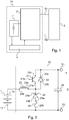
- the figure 1 represents an interface device 2 connected to an auxiliary power supply system 1 and to a power generation module 3.
- railway vehicles are supplied with electrical energy by means of a main power system or network (not visible in the figures).
- Auxiliary power systems 1 are present in the vehicles to generate electrical power to certain parts of the vehicle in the absence of power supply through the main power system.
- This auxiliary power supply system 1 is for example a battery or electric storage battery.
- This battery 1 is charged with electrical energy by means of a power generator module 3.
- This energy generator module 3 is for example a battery charger.
- the auxiliary power supply system 1 is a battery 1 and the power generator module 3 is a battery charger 3.
- the battery 1 is of a second type, that is to say that it is implemented according to a second technology
- the energy generator module 3 has been designed to operate in combination with a first type of battery, that is to say that it was designed to deliver electrical energy to a first type of battery.
- the battery 1 (second type of battery) is a Lithium Iron Phosphate (LiFePO 4 ) type battery, known as the LPF battery.
- LiFePO 4 Lithium Iron Phosphate
- the second types of batteries 1 may be different, for example Lithium-Nickel-Cobalt-Aluminum (NCA) or Lithium-Nickel-Manganese Cobalt (NMC).
- NCA Lithium-Nickel-Cobalt-Aluminum
- NMC Lithium-Nickel-Manganese Cobalt
- the battery charger 3 is designed to work in combination with Ni-Cd type batteries.
- the battery chargers can be designed to work in combination with different types of batteries.
- the battery 1 of the second type and the battery charger 3 are connected through an interface device 2.
- An embodiment of this interface device 2 will be described with reference to FIG. figure 2 .
- battery 1 corresponds to a battery 1 of the second type.
- Control means 4 are able to manage the operation of an assembly 10 formed by the interface device 2 and the battery 1.
- control means 4 configure the interface device 2 so that the battery 1 is in charge or discharge mode, the charging mode corresponding to a mode in which the battery 1 is charged with electrical energy from of the battery charger 3, and the discharge mode corresponding to a mode in which the battery 1 supplies electrical energy to certain parts of the railway vehicle.
- the figure 2 represents a battery 1 and an embodiment of the interface device 2 according to the invention.
- the interface device 2 comprises connection means to the battery charger 3 and the LFP type batteries.
- the connecting means are electrical connectors capable of establishing an electrical connection between the battery 1 and the interface device 2, and between the battery charger 3 and the interface device 2.
- the interface device 2 further comprises interface means 20 adapted for operation of the LFP type battery in combination with the battery charger 3 adapted to operate in combination with Ni-Cd type batteries.
- railway vehicles that had been equipped with batteries of a first type, for example of the Ni-Cd type and battery chargers designed to operate with this type of battery, can today be updated with batteries. other types without having to replace the battery chargers.
- the interface means 20 of the interface device 2 comprise means for transferring the energy delivered by the battery charger 3 to the battery 1.
- These energy transfer means delivered by the battery charger 3 are designed to electrically connect the battery 1 and the charger 3 so that the battery 1 is electrically charged.
- the energy transfer means delivered by the battery charger 3 comprise a charge transistor 21.
- the load transistor 21 can be of different types, such as a field-effect transistor (FET, the acronym for "Field Effect Transistor”), such as a MOSFET, JFET or other, or a bipolar transistor, or a transistor hybrid bipolar and FET, such as an IGBT transistor.
- FET field-effect transistor
- MOSFET MOSFET
- JFET field-effect transistor
- bipolar transistor bipolar transistor
- transistor hybrid bipolar and FET such as an IGBT transistor.
- the interface means 20 further comprise means for transferring electrical energy from the battery 1 to the battery charger 3.
- These means for transferring electrical energy from the battery 1 to the battery charger 3 are designed to electrically connect the battery 1 and the battery charger 3 so that the electrical energy that has been stored in the battery 1 is transferred to the network or main power system of the vehicle.
- the means for transferring electrical energy from the battery 1 to the battery charger 3 comprise a discharge diode 22.
- the interface means 20 further comprise security means 24, 25 connected in parallel with the battery 1.
- the security means comprise a security diode 24 and a fuse 25.
- the security means 24, 25 prevent the battery 1 from being in a short-circuit configuration, which would damage the battery 1.
- the security means 22, 24 protect the battery 1 from possible faults in the interface device 2 and in the battery charger 3 which could cause its damage.
- the battery 1 provide electrical power to certain electrical circuits during failures of the main power system.
- the interface means 20 further comprise energy storage means.
- the energy storage means comprise an inductor 23.
- This inductor 23 is able to store electrical energy from the battery charger 3 or from the battery 1
- the inductor 23 stores this electrical energy from the battery charger 3 and then releases this energy to the battery 1.
- the inductor 23 stores the energy from the battery 1 and then releases it to the battery charger 3 and the main power grid.
- the interface device 2 described with reference to the figure 2 comprises a charge transistor 21 connected by its collector 21c to the cathode 22a of the discharge diode 22, this discharge diode 22 being connected by its anode 22b to the emitter 22e of the charge transistor 21.
- This charge transistor is here a bipolar transistor NPN type.
- a close control circuit (not shown) (better known by its English “ driver " terminology) is connected to the base 21b of the load transistor 21.
- the driver receives a control signal from the control means 4 enabling the repair operating or shutting down the load transistor 21.
- the control signal can be generated by a pulse modulation regulator (PWM), known in Anglo-Saxon nomenclature as PWM (" Pulse Width Modulation ").
- PWM pulse modulation regulator
- the energy transferred to the battery 1 is thus regulated according to the width of the pulse of the control signal.
- the emitter 21e of the load transistor 21 and the anode 22b of the discharge diode 22 are connected to a first terminal 23a of the inductor 23.
- This inductor 23 is connected by a second terminal 23b to the positive pole 1a of the battery 1.
- the anode 22b of the discharge diode 22, the first terminal 23a of the inductor 23 and the emitter 21e of the load transistor 21 are connected to the cathode 24a of the security diode 24.
- the anode 24b of the safety diode 24 is connected to the fuse 25, this fuse 25 being further connected to the negative pole 1b of the battery 1.
- the security diode 24 and the fuse 25 are arranged in parallel with the battery 1.
- the cathode 22a of the discharge diode 22 and the collector 21c of the load transistor 21 constitute the positive terminal s 1 of the output s of the interface device 2.
- the negative pole of the battery 1 and a second terminal 25b of the fuse 25 constitute the negative terminal s 2 of the output s of the interface device 2.
- An output capacitor 26 is disposed at the output s of the interface device 2, in order to constitute a potential difference between the positive terminal s 1 and the negative terminal s 2 of the output s .
- connection of the interface device 2 to the battery charger 3 is implemented through the positive terminal s 1 and the negative terminal s 2 of the output of the interface device 2.
- the positive terminal s 1 and the negative terminal s 2 of the output of the interface device constitute means for connecting the interface device 2 to the battery charger 3.
- the charging transistor 21 When the battery 1 is in the charging mode, that is to say when it is charged with electrical energy by the battery charger 3, the charging transistor 21 is put into an on mode or operating mode, and the discharge diode 22 and the security diode 24 are not in conduction.
- a charging current flows from the battery charger 3 to the inductor 23, the electrical energy delivered by the battery charger 3 being stored in the inductor 23.
- This inductance is dimensioned such that it is able to withstand the passage of the current of the battery charger 3 to the battery 1 in charge mode.
- the load transistor 21 When the battery 1 is in discharge mode, that is to say that it must power certain parts of the railway vehicle, the load transistor 21 is put in off mode.
- the discharge diode 22 is conducting, and a discharge current (not shown in the figure) from the battery 1 and the inductor 23 passes through the discharge diode 22 to arrive at the main supply network.
- the security diode 24 As for the case in which the battery 1 is in charging mode, the security diode 24 is not conducting, has no influence on the operation in the discharge mode of the battery 1.
- the battery charger 3 is unidirectional, that is to say it can transmit energy but it does not consume energy.
- the inductor can operate in saturation.
- the security diode 24 and the fuse 25 are arranged in parallel with the battery 1 to protect it from a possible short circuit.
- the fuse 25 is destroyed by the current flowing through the diode, which prevents the short circuit of the battery 1.
- the batteries present in railway vehicles in particular Ni-Cd type batteries, can be replaced by other types of batteries, in particular by LFP type batteries, without replacing the battery charger.
- the interface device according to the invention could be installed in vehicles other than railway vehicles.
Landscapes
- Engineering & Computer Science (AREA)
- Power Engineering (AREA)
- Business, Economics & Management (AREA)
- Emergency Management (AREA)
- Charge And Discharge Circuits For Batteries Or The Like (AREA)
Claims (7)
- Aufbau, umfassend ein Hilfsstromversorgungssystem (1) und eine Schnittstellenvorrichtung (2) zwischen dem Hilfsstromversorgungssystem (1) und einem Energiegewinnungsmodul (3) bei einem Schienenfahrzeug, wobei das Energiegewinnungsmodul (3) dafür ausgelegt ist, ein Hilfsstromversorgungssystem, das gemäß einer anderen Technologie als das Hilfsstromversorgungssystem (1) verwendet wird, mit elektrischer Energie aufzuladen, wobei der Aufbau dadurch gekennzeichnet ist, dass die Schnittstellenvorrichtung (2) Verbindungsmittel zu dem Energiegewinnungsmodul (3) und dem Hilfsstromversorgungssystem (1) enthält und dass die Schnittstellenvorrichtung (2) Schnittstellenmittel (20) enthält, die für den Betrieb des Hilfsstromversorgungssystems (1) in Kombination mit dem Energiegewinnungsmodul (3) ausgelegt sind, wobei die Schnittstellenmittel (20) Sicherungsmittel (24, 25) enthalten, die zu dem Hilfsstromversorgungssystem (1) parallelgeschaltet sind.
- Aufbau nach Anspruch 1, dadurch gekennzeichnet, dass das Energiegewinnungsmodul (3) für die Energielieferung konzipierte Auflademittel enthält, wobei die Schnittstellenmittel (20) Übertragungsmittel (21) zur Übertragung der von den Auflademitteln des Energiegewinnungsmoduls (3) gelieferten elektrischen Energie zu dem Hilfsstromversorgungssystem (1) enthalten.
- Aufbau nach einem der Ansprüche 1 oder 2, dadurch gekennzeichnet, dass die Schnittstellenmittel (20) darüber hinaus Mittel zur Übertragung von elektrischer Energie (22) aus dem Hilfsstromversorgungssystem (1) zu dem Energiegewinnungsmodul (3) enthalten.
- Aufbau nach einem der Ansprüche 1 bis 3, dadurch gekennzeichnet, dass die Schnittstellenmittel (20) Energiespeichermittel (23) enthalten.
- Aufbau nach einem der Ansprüche 1 bis 4, dadurch gekennzeichnet, dass es sich bei dem Hilfsstromversorgungssystem (1) um eine Lithium-Eisen-Phosphat-Batterie handelt.
- Schienenfahrzeug, umfassend einen Aufbau nach einem der Ansprüche 1 bis 5.
- Betriebsinstandhaltungsverfahren bei einem Schienenfahrzeug, wobei das Schienenfahrzeug ein Hilfsstromversorgungssystem, das gemäß einer ersten Technologie verwendet wird, und ein Energiegewinnungsmodul (3) enthält, wobei das Energiegewinnungsmodul (3) dafür ausgelegt ist, das Hilfsstromversorgungssystem mit elektrischer Energie aufzuladen, wobei das Betriebsinstandhaltungsverfahren dadurch gekennzeichnet ist, dass es das Ersetzen des Hilfsstromversorgungssystems durch einen Aufbau umfasst, welcher aus einem Hilfsstromversorgungssystem (1), das gemäß einer zweiten Technologie, die sich von der ersten Technologie unterscheidet, verwendet wird, und aus einer Schnittstellenvorrichtung (2) gebildet ist, wobei die Schnittstellenvorrichtung (2) zwischen dem Hilfsstromversorgungssystem (1) des Aufbaus und dem Energiegewinnungsmodul (3) angeordnet ist und Schnittstellenmittel (20) enthält, die für den Betrieb des Hilfsstromversorgungssystems (1) des Aufbaus in Kombination mit dem Energiegewinnungsmodul (3) ausgelegt sind, wobei die Schnittstellenmittel (20) Sicherungsmittel (24, 25) enthalten, die zu dem Hilfsstromversorgungssystem (1) parallelgeschaltet sind.
Applications Claiming Priority (2)
| Application Number | Priority Date | Filing Date | Title |
|---|---|---|---|
| FR1352977A FR3004020B1 (fr) | 2013-04-02 | 2013-04-02 | Dispositif d'interface entre un systeme d'alimentation auxiliaire et un module de generation d'energie dans un vehicule ferroviaire |
| PCT/FR2014/050773 WO2014162090A1 (fr) | 2013-04-02 | 2014-04-01 | Dispositif d'interface entre un système d'alimentation auxiliaire et un module de génération d'énergie dans un véhicule ferroviaire |
Publications (2)
| Publication Number | Publication Date |
|---|---|
| EP2982019A1 EP2982019A1 (de) | 2016-02-10 |
| EP2982019B1 true EP2982019B1 (de) | 2017-08-02 |
Family
ID=48741382
Family Applications (1)
| Application Number | Title | Priority Date | Filing Date |
|---|---|---|---|
| EP14721450.6A Active EP2982019B1 (de) | 2013-04-02 | 2014-04-01 | Vorrichtung zur bildung einer schnittstelle zwischen einem hilfsstromversorgungssystem und energiegewinnungsmodul in einem schienenfahrzeug |
Country Status (6)
| Country | Link |
|---|---|
| US (1) | US10608465B2 (de) |
| EP (1) | EP2982019B1 (de) |
| CN (1) | CN105144539B (de) |
| FR (1) | FR3004020B1 (de) |
| SG (1) | SG11201508016PA (de) |
| WO (1) | WO2014162090A1 (de) |
Families Citing this family (1)
| Publication number | Priority date | Publication date | Assignee | Title |
|---|---|---|---|---|
| CN105034828A (zh) * | 2015-06-26 | 2015-11-11 | 中国北车集团大连机车车辆有限公司 | 电力城轨车辆组无电调车作业方法 |
Citations (4)
| Publication number | Priority date | Publication date | Assignee | Title |
|---|---|---|---|---|
| FR2919768A1 (fr) * | 2007-08-03 | 2009-02-06 | Alstom Transport Sa | Procede d'alimentation de charges auxiliaires de secours, convertisseur auxiliaire et vehicule ferroviaire pour ce procede. |
| EP2204893A1 (de) * | 2009-01-05 | 2010-07-07 | Samya Technology Co., Ltd. | Universelles Batterieladegerät |
| US20110163722A1 (en) * | 2010-03-11 | 2011-07-07 | Ford Global Technologies, Llc | Vehicle and method of charging battery of same |
| WO2013038441A1 (ja) * | 2011-09-13 | 2013-03-21 | トヨタ自動車株式会社 | 車両の電池システムと、この制御方法 |
Family Cites Families (6)
| Publication number | Priority date | Publication date | Assignee | Title |
|---|---|---|---|---|
| WO2005084335A2 (en) * | 2004-03-01 | 2005-09-15 | Railpower Technologies Corp. | Cabless hybrid locomotive |
| US7538684B2 (en) * | 2004-08-18 | 2009-05-26 | Hamilton Sundstrand Corporation | Circuit health monitoring system and method |
| JP5563577B2 (ja) * | 2008-09-11 | 2014-07-30 | イートレックス・インコーポレーテッド | 双方向インバータ・チャージャ及びインバータ・チャージャ装置 |
| US8115446B2 (en) * | 2008-11-12 | 2012-02-14 | Ford Global Technologies, Llc | Automotive vehicle power system |
| BR112013015730A2 (pt) * | 2010-12-23 | 2018-05-15 | Siemens S.A.S | método de regulagem de tensão de alimentação elétrica para um funcionamento de pelo menos um veículo alimentado eletricamente. |
| FR2972581B1 (fr) * | 2011-03-09 | 2015-01-02 | Commissariat Energie Atomique | Systeme d'equilibrage de charge pour batteries |
-
2013
- 2013-04-02 FR FR1352977A patent/FR3004020B1/fr active Active
-
2014
- 2014-04-01 EP EP14721450.6A patent/EP2982019B1/de active Active
- 2014-04-01 SG SG11201508016PA patent/SG11201508016PA/en unknown
- 2014-04-01 WO PCT/FR2014/050773 patent/WO2014162090A1/fr not_active Ceased
- 2014-04-01 CN CN201480019913.6A patent/CN105144539B/zh active Active
- 2014-04-01 US US14/781,729 patent/US10608465B2/en active Active
Patent Citations (5)
| Publication number | Priority date | Publication date | Assignee | Title |
|---|---|---|---|---|
| FR2919768A1 (fr) * | 2007-08-03 | 2009-02-06 | Alstom Transport Sa | Procede d'alimentation de charges auxiliaires de secours, convertisseur auxiliaire et vehicule ferroviaire pour ce procede. |
| EP2204893A1 (de) * | 2009-01-05 | 2010-07-07 | Samya Technology Co., Ltd. | Universelles Batterieladegerät |
| US20110163722A1 (en) * | 2010-03-11 | 2011-07-07 | Ford Global Technologies, Llc | Vehicle and method of charging battery of same |
| WO2013038441A1 (ja) * | 2011-09-13 | 2013-03-21 | トヨタ自動車株式会社 | 車両の電池システムと、この制御方法 |
| US8884461B2 (en) * | 2011-09-13 | 2014-11-11 | Toyota Jidosha Kabushiki Kaisha | Battery system for vehicle and control method thereof |
Also Published As
| Publication number | Publication date |
|---|---|
| US20160043593A1 (en) | 2016-02-11 |
| WO2014162090A1 (fr) | 2014-10-09 |
| CN105144539B (zh) | 2019-11-01 |
| SG11201508016PA (en) | 2015-10-29 |
| CN105144539A (zh) | 2015-12-09 |
| EP2982019A1 (de) | 2016-02-10 |
| FR3004020B1 (fr) | 2015-05-01 |
| FR3004020A1 (fr) | 2014-10-03 |
| US10608465B2 (en) | 2020-03-31 |
Similar Documents
| Publication | Publication Date | Title |
|---|---|---|
| EP3016817B1 (de) | Elektrofahrzeug und verbundene transporteinrichtung | |
| EP2721666B1 (de) | Sicheres batterieelement | |
| EP3105845B1 (de) | Gleichspannungsversorgungssystem zur vorladung eines glättungskondensators vor der speisung einer last | |
| EP3049277B1 (de) | Verfahren und system zur energieverwaltung an bord eines fahrzeuges | |
| EP2524397B1 (de) | System zur verwaltung und steuerung von pv-modulen | |
| EP2781001B1 (de) | Gleichspannungsquelle einschliesslich brennstoffzellen mit anpassungfähigem spannungspegel | |
| WO2013072358A1 (fr) | Batterie d'accumulateurs protegee contre les courts-circuits internes | |
| EP2982019B1 (de) | Vorrichtung zur bildung einer schnittstelle zwischen einem hilfsstromversorgungssystem und energiegewinnungsmodul in einem schienenfahrzeug | |
| FR2987511A1 (fr) | Dispositif de prise de tension continue pour une installation de stockage d'energie et procede pour generer une tension continue a partir d'une installation de stockage d'energie | |
| FR3068789A1 (fr) | Dispositif de protection contre un court-circuit dans un reseau electrique d’un systeme pendant une recharge rapide d’une batterie | |
| WO2015071581A1 (fr) | Dispositif et procede de recharge d'un stockeur d'energie electrique d'un vehicule automobile | |
| EP4530122A1 (de) | Stromversorgungssystem mit brennstoffzelle | |
| WO2019110296A1 (fr) | Convertisseur continu-continu pour vehicule electrique ou hybride avec recuperation des pertes au secondaire | |
| FR3083173A1 (fr) | Systeme de stockage d'energie embarque | |
| FR2955210A1 (fr) | Systeme de gestion et de commande de panneaux photovoltaiques | |
| FR2943150A1 (fr) | Dispositif d'alimentation en courant regule et systeme d'alimentation en tension regulee et courant regule pour au moins un organe electrique connecte a un reseau d'alimentation electrique | |
| FR2955208A1 (fr) | Systeme de gestion et de commande de panneaux photovoltaiques | |
| FR2934929A1 (fr) | Systeme de stockage d'energie electrique pour vehicule automobile et procede de gestion d'energie dans un tel systeme. | |
| FR3016752A1 (fr) | Procede de recharge d'un stockeur d'energie electrique d'un vehicule automobile | |
| FR3017830A1 (fr) | Procede de recharge d'un stockeur d'energie electrique d'un vehicule automobile |
Legal Events
| Date | Code | Title | Description |
|---|---|---|---|
| PUAI | Public reference made under article 153(3) epc to a published international application that has entered the european phase |
Free format text: ORIGINAL CODE: 0009012 |
|
| 17P | Request for examination filed |
Effective date: 20151014 |
|
| AK | Designated contracting states |
Kind code of ref document: A1 Designated state(s): AL AT BE BG CH CY CZ DE DK EE ES FI FR GB GR HR HU IE IS IT LI LT LU LV MC MK MT NL NO PL PT RO RS SE SI SK SM TR |
|
| AX | Request for extension of the european patent |
Extension state: BA ME |
|
| DAX | Request for extension of the european patent (deleted) | ||
| STAA | Information on the status of an ep patent application or granted ep patent |
Free format text: STATUS: EXAMINATION IS IN PROGRESS |
|
| 17Q | First examination report despatched |
Effective date: 20161021 |
|
| GRAP | Despatch of communication of intention to grant a patent |
Free format text: ORIGINAL CODE: EPIDOSNIGR1 |
|
| STAA | Information on the status of an ep patent application or granted ep patent |
Free format text: STATUS: GRANT OF PATENT IS INTENDED |
|
| RIC1 | Information provided on ipc code assigned before grant |
Ipc: H02J 9/06 20060101ALI20170427BHEP Ipc: H02M 3/155 20060101ALI20170427BHEP Ipc: H02J 7/00 20060101AFI20170427BHEP |
|
| INTG | Intention to grant announced |
Effective date: 20170523 |
|
| GRAS | Grant fee paid |
Free format text: ORIGINAL CODE: EPIDOSNIGR3 |
|
| GRAA | (expected) grant |
Free format text: ORIGINAL CODE: 0009210 |
|
| STAA | Information on the status of an ep patent application or granted ep patent |
Free format text: STATUS: THE PATENT HAS BEEN GRANTED |
|
| AK | Designated contracting states |
Kind code of ref document: B1 Designated state(s): AL AT BE BG CH CY CZ DE DK EE ES FI FR GB GR HR HU IE IS IT LI LT LU LV MC MK MT NL NO PL PT RO RS SE SI SK SM TR |
|
| REG | Reference to a national code |
Ref country code: CH Ref legal event code: EP Ref country code: AT Ref legal event code: REF Ref document number: 915458 Country of ref document: AT Kind code of ref document: T Effective date: 20170815 |
|
| REG | Reference to a national code |
Ref country code: IE Ref legal event code: FG4D Free format text: LANGUAGE OF EP DOCUMENT: FRENCH |
|
| REG | Reference to a national code |
Ref country code: DE Ref legal event code: R096 Ref document number: 602014012553 Country of ref document: DE |
|
| REG | Reference to a national code |
Ref country code: CH Ref legal event code: NV Representative=s name: KIRKER AND CIE S.A., CH |
|
| REG | Reference to a national code |
Ref country code: NL Ref legal event code: MP Effective date: 20170802 |
|
| REG | Reference to a national code |
Ref country code: AT Ref legal event code: MK05 Ref document number: 915458 Country of ref document: AT Kind code of ref document: T Effective date: 20170802 |
|
| REG | Reference to a national code |
Ref country code: LT Ref legal event code: MG4D |
|
| PG25 | Lapsed in a contracting state [announced via postgrant information from national office to epo] |
Ref country code: AT Free format text: LAPSE BECAUSE OF FAILURE TO SUBMIT A TRANSLATION OF THE DESCRIPTION OR TO PAY THE FEE WITHIN THE PRESCRIBED TIME-LIMIT Effective date: 20170802 Ref country code: NL Free format text: LAPSE BECAUSE OF FAILURE TO SUBMIT A TRANSLATION OF THE DESCRIPTION OR TO PAY THE FEE WITHIN THE PRESCRIBED TIME-LIMIT Effective date: 20170802 Ref country code: NO Free format text: LAPSE BECAUSE OF FAILURE TO SUBMIT A TRANSLATION OF THE DESCRIPTION OR TO PAY THE FEE WITHIN THE PRESCRIBED TIME-LIMIT Effective date: 20171102 Ref country code: HR Free format text: LAPSE BECAUSE OF FAILURE TO SUBMIT A TRANSLATION OF THE DESCRIPTION OR TO PAY THE FEE WITHIN THE PRESCRIBED TIME-LIMIT Effective date: 20170802 Ref country code: LT Free format text: LAPSE BECAUSE OF FAILURE TO SUBMIT A TRANSLATION OF THE DESCRIPTION OR TO PAY THE FEE WITHIN THE PRESCRIBED TIME-LIMIT Effective date: 20170802 Ref country code: FI Free format text: LAPSE BECAUSE OF FAILURE TO SUBMIT A TRANSLATION OF THE DESCRIPTION OR TO PAY THE FEE WITHIN THE PRESCRIBED TIME-LIMIT Effective date: 20170802 Ref country code: SE Free format text: LAPSE BECAUSE OF FAILURE TO SUBMIT A TRANSLATION OF THE DESCRIPTION OR TO PAY THE FEE WITHIN THE PRESCRIBED TIME-LIMIT Effective date: 20170802 |
|
| REG | Reference to a national code |
Ref country code: FR Ref legal event code: PLFP Year of fee payment: 5 |
|
| PG25 | Lapsed in a contracting state [announced via postgrant information from national office to epo] |
Ref country code: RS Free format text: LAPSE BECAUSE OF FAILURE TO SUBMIT A TRANSLATION OF THE DESCRIPTION OR TO PAY THE FEE WITHIN THE PRESCRIBED TIME-LIMIT Effective date: 20170802 Ref country code: PL Free format text: LAPSE BECAUSE OF FAILURE TO SUBMIT A TRANSLATION OF THE DESCRIPTION OR TO PAY THE FEE WITHIN THE PRESCRIBED TIME-LIMIT Effective date: 20170802 Ref country code: ES Free format text: LAPSE BECAUSE OF FAILURE TO SUBMIT A TRANSLATION OF THE DESCRIPTION OR TO PAY THE FEE WITHIN THE PRESCRIBED TIME-LIMIT Effective date: 20170802 Ref country code: LV Free format text: LAPSE BECAUSE OF FAILURE TO SUBMIT A TRANSLATION OF THE DESCRIPTION OR TO PAY THE FEE WITHIN THE PRESCRIBED TIME-LIMIT Effective date: 20170802 Ref country code: IS Free format text: LAPSE BECAUSE OF FAILURE TO SUBMIT A TRANSLATION OF THE DESCRIPTION OR TO PAY THE FEE WITHIN THE PRESCRIBED TIME-LIMIT Effective date: 20171202 Ref country code: BG Free format text: LAPSE BECAUSE OF FAILURE TO SUBMIT A TRANSLATION OF THE DESCRIPTION OR TO PAY THE FEE WITHIN THE PRESCRIBED TIME-LIMIT Effective date: 20171102 Ref country code: GR Free format text: LAPSE BECAUSE OF FAILURE TO SUBMIT A TRANSLATION OF THE DESCRIPTION OR TO PAY THE FEE WITHIN THE PRESCRIBED TIME-LIMIT Effective date: 20171103 |
|
| PG25 | Lapsed in a contracting state [announced via postgrant information from national office to epo] |
Ref country code: RO Free format text: LAPSE BECAUSE OF FAILURE TO SUBMIT A TRANSLATION OF THE DESCRIPTION OR TO PAY THE FEE WITHIN THE PRESCRIBED TIME-LIMIT Effective date: 20170802 Ref country code: DK Free format text: LAPSE BECAUSE OF FAILURE TO SUBMIT A TRANSLATION OF THE DESCRIPTION OR TO PAY THE FEE WITHIN THE PRESCRIBED TIME-LIMIT Effective date: 20170802 Ref country code: CZ Free format text: LAPSE BECAUSE OF FAILURE TO SUBMIT A TRANSLATION OF THE DESCRIPTION OR TO PAY THE FEE WITHIN THE PRESCRIBED TIME-LIMIT Effective date: 20170802 |
|
| REG | Reference to a national code |
Ref country code: DE Ref legal event code: R097 Ref document number: 602014012553 Country of ref document: DE |
|
| PG25 | Lapsed in a contracting state [announced via postgrant information from national office to epo] |
Ref country code: SM Free format text: LAPSE BECAUSE OF FAILURE TO SUBMIT A TRANSLATION OF THE DESCRIPTION OR TO PAY THE FEE WITHIN THE PRESCRIBED TIME-LIMIT Effective date: 20170802 Ref country code: SK Free format text: LAPSE BECAUSE OF FAILURE TO SUBMIT A TRANSLATION OF THE DESCRIPTION OR TO PAY THE FEE WITHIN THE PRESCRIBED TIME-LIMIT Effective date: 20170802 Ref country code: EE Free format text: LAPSE BECAUSE OF FAILURE TO SUBMIT A TRANSLATION OF THE DESCRIPTION OR TO PAY THE FEE WITHIN THE PRESCRIBED TIME-LIMIT Effective date: 20170802 |
|
| PLBE | No opposition filed within time limit |
Free format text: ORIGINAL CODE: 0009261 |
|
| STAA | Information on the status of an ep patent application or granted ep patent |
Free format text: STATUS: NO OPPOSITION FILED WITHIN TIME LIMIT |
|
| 26N | No opposition filed |
Effective date: 20180503 |
|
| PG25 | Lapsed in a contracting state [announced via postgrant information from national office to epo] |
Ref country code: SI Free format text: LAPSE BECAUSE OF FAILURE TO SUBMIT A TRANSLATION OF THE DESCRIPTION OR TO PAY THE FEE WITHIN THE PRESCRIBED TIME-LIMIT Effective date: 20170802 |
|
| PG25 | Lapsed in a contracting state [announced via postgrant information from national office to epo] |
Ref country code: MT Free format text: LAPSE BECAUSE OF FAILURE TO SUBMIT A TRANSLATION OF THE DESCRIPTION OR TO PAY THE FEE WITHIN THE PRESCRIBED TIME-LIMIT Effective date: 20170802 |
|
| PG25 | Lapsed in a contracting state [announced via postgrant information from national office to epo] |
Ref country code: MC Free format text: LAPSE BECAUSE OF FAILURE TO SUBMIT A TRANSLATION OF THE DESCRIPTION OR TO PAY THE FEE WITHIN THE PRESCRIBED TIME-LIMIT Effective date: 20170802 |
|
| REG | Reference to a national code |
Ref country code: BE Ref legal event code: MM Effective date: 20180430 |
|
| REG | Reference to a national code |
Ref country code: IE Ref legal event code: MM4A |
|
| PG25 | Lapsed in a contracting state [announced via postgrant information from national office to epo] |
Ref country code: LU Free format text: LAPSE BECAUSE OF NON-PAYMENT OF DUE FEES Effective date: 20180401 |
|
| PG25 | Lapsed in a contracting state [announced via postgrant information from national office to epo] |
Ref country code: BE Free format text: LAPSE BECAUSE OF NON-PAYMENT OF DUE FEES Effective date: 20180430 |
|
| PG25 | Lapsed in a contracting state [announced via postgrant information from national office to epo] |
Ref country code: IE Free format text: LAPSE BECAUSE OF NON-PAYMENT OF DUE FEES Effective date: 20180401 |
|
| PG25 | Lapsed in a contracting state [announced via postgrant information from national office to epo] |
Ref country code: TR Free format text: LAPSE BECAUSE OF FAILURE TO SUBMIT A TRANSLATION OF THE DESCRIPTION OR TO PAY THE FEE WITHIN THE PRESCRIBED TIME-LIMIT Effective date: 20170802 |
|
| PG25 | Lapsed in a contracting state [announced via postgrant information from national office to epo] |
Ref country code: PT Free format text: LAPSE BECAUSE OF FAILURE TO SUBMIT A TRANSLATION OF THE DESCRIPTION OR TO PAY THE FEE WITHIN THE PRESCRIBED TIME-LIMIT Effective date: 20170802 |
|
| PG25 | Lapsed in a contracting state [announced via postgrant information from national office to epo] |
Ref country code: HU Free format text: LAPSE BECAUSE OF FAILURE TO SUBMIT A TRANSLATION OF THE DESCRIPTION OR TO PAY THE FEE WITHIN THE PRESCRIBED TIME-LIMIT; INVALID AB INITIO Effective date: 20140401 Ref country code: CY Free format text: LAPSE BECAUSE OF FAILURE TO SUBMIT A TRANSLATION OF THE DESCRIPTION OR TO PAY THE FEE WITHIN THE PRESCRIBED TIME-LIMIT Effective date: 20170802 Ref country code: MK Free format text: LAPSE BECAUSE OF NON-PAYMENT OF DUE FEES Effective date: 20170802 |
|
| PG25 | Lapsed in a contracting state [announced via postgrant information from national office to epo] |
Ref country code: AL Free format text: LAPSE BECAUSE OF FAILURE TO SUBMIT A TRANSLATION OF THE DESCRIPTION OR TO PAY THE FEE WITHIN THE PRESCRIBED TIME-LIMIT Effective date: 20170802 |
|
| P01 | Opt-out of the competence of the unified patent court (upc) registered |
Effective date: 20230530 |
|
| PGFP | Annual fee paid to national office [announced via postgrant information from national office to epo] |
Ref country code: DE Payment date: 20250331 Year of fee payment: 12 |
|
| PGFP | Annual fee paid to national office [announced via postgrant information from national office to epo] |
Ref country code: IT Payment date: 20250328 Year of fee payment: 12 |
|
| PGFP | Annual fee paid to national office [announced via postgrant information from national office to epo] |
Ref country code: CH Payment date: 20250501 Year of fee payment: 12 |
|
| PGFP | Annual fee paid to national office [announced via postgrant information from national office to epo] |
Ref country code: GB Payment date: 20260316 Year of fee payment: 13 |
|
| PGFP | Annual fee paid to national office [announced via postgrant information from national office to epo] |
Ref country code: FR Payment date: 20260312 Year of fee payment: 13 |