EP2982135B1 - Écouteur intra-auriculaire avec embout auriculaire sur mesure - Google Patents
Écouteur intra-auriculaire avec embout auriculaire sur mesure Download PDFInfo
- Publication number
- EP2982135B1 EP2982135B1 EP14714708.6A EP14714708A EP2982135B1 EP 2982135 B1 EP2982135 B1 EP 2982135B1 EP 14714708 A EP14714708 A EP 14714708A EP 2982135 B1 EP2982135 B1 EP 2982135B1
- Authority
- EP
- European Patent Office
- Prior art keywords
- sound
- guide unit
- sound guide
- ear canal
- ear
- Prior art date
- Legal status (The legal status is an assumption and is not a legal conclusion. Google has not performed a legal analysis and makes no representation as to the accuracy of the status listed.)
- Active
Links
Images



Classifications
-
- H—ELECTRICITY
- H04—ELECTRIC COMMUNICATION TECHNIQUE
- H04R—LOUDSPEAKERS, MICROPHONES, GRAMOPHONE PICK-UPS OR LIKE ACOUSTIC ELECTROMECHANICAL TRANSDUCERS; ELECTRIC HEARING AIDS; PUBLIC ADDRESS SYSTEMS
- H04R1/00—Details of transducers, loudspeakers or microphones
- H04R1/10—Earpieces; Attachments therefor ; Earphones; Monophonic headphones
- H04R1/1016—Earpieces of the intra-aural type
-
- H—ELECTRICITY
- H04—ELECTRIC COMMUNICATION TECHNIQUE
- H04R—LOUDSPEAKERS, MICROPHONES, GRAMOPHONE PICK-UPS OR LIKE ACOUSTIC ELECTROMECHANICAL TRANSDUCERS; ELECTRIC HEARING AIDS; PUBLIC ADDRESS SYSTEMS
- H04R25/00—Electric hearing aids
- H04R25/65—Housing parts, e.g. shells, tips or moulds, or their manufacture
- H04R25/652—Ear tips; Ear moulds
-
- G—PHYSICS
- G10—MUSICAL INSTRUMENTS; ACOUSTICS
- G10K—SOUND-PRODUCING DEVICES; METHODS OR DEVICES FOR PROTECTING AGAINST, OR FOR DAMPING, NOISE OR OTHER ACOUSTIC WAVES IN GENERAL; ACOUSTICS NOT OTHERWISE PROVIDED FOR
- G10K11/00—Methods or devices for transmitting, conducting or directing sound in general; Methods or devices for protecting against, or for damping, noise or other acoustic waves in general
- G10K11/002—Devices for damping, suppressing, obstructing or conducting sound in acoustic devices
-
- G—PHYSICS
- G10—MUSICAL INSTRUMENTS; ACOUSTICS
- G10K—SOUND-PRODUCING DEVICES; METHODS OR DEVICES FOR PROTECTING AGAINST, OR FOR DAMPING, NOISE OR OTHER ACOUSTIC WAVES IN GENERAL; ACOUSTICS NOT OTHERWISE PROVIDED FOR
- G10K11/00—Methods or devices for transmitting, conducting or directing sound in general; Methods or devices for protecting against, or for damping, noise or other acoustic waves in general
- G10K11/18—Methods or devices for transmitting, conducting or directing sound
- G10K11/22—Methods or devices for transmitting, conducting or directing sound for conducting sound through hollow pipes, e.g. speaking tubes
-
- H—ELECTRICITY
- H04—ELECTRIC COMMUNICATION TECHNIQUE
- H04R—LOUDSPEAKERS, MICROPHONES, GRAMOPHONE PICK-UPS OR LIKE ACOUSTIC ELECTROMECHANICAL TRANSDUCERS; ELECTRIC HEARING AIDS; PUBLIC ADDRESS SYSTEMS
- H04R1/00—Details of transducers, loudspeakers or microphones
- H04R1/20—Arrangements for obtaining desired frequency or directional characteristics
- H04R1/22—Arrangements for obtaining desired frequency or directional characteristics for obtaining desired frequency characteristic only
- H04R1/28—Transducer mountings or enclosures modified by provision of mechanical or acoustic impedances, e.g. resonator, damping means
- H04R1/2869—Reduction of undesired resonances, i.e. standing waves within enclosure, or of undesired vibrations, i.e. of the enclosure itself
- H04R1/2873—Reduction of undesired resonances, i.e. standing waves within enclosure, or of undesired vibrations, i.e. of the enclosure itself for loudspeaker transducers
-
- G—PHYSICS
- G10—MUSICAL INSTRUMENTS; ACOUSTICS
- G10K—SOUND-PRODUCING DEVICES; METHODS OR DEVICES FOR PROTECTING AGAINST, OR FOR DAMPING, NOISE OR OTHER ACOUSTIC WAVES IN GENERAL; ACOUSTICS NOT OTHERWISE PROVIDED FOR
- G10K2210/00—Details of active noise control [ANC] covered by G10K11/178 but not provided for in any of its subgroups
- G10K2210/30—Means
- G10K2210/321—Physical
- G10K2210/3227—Resonators
- G10K2210/32272—Helmholtz resonators
Definitions
- the invention relates to an ear canal earpiece.
- Ear canal earphones generally have an acoustic transducer that is built into a housing that is inserted intra-aurally, that is, into the ear canal.
- An ear cushion is often arranged around the housing, so that wearing the ear canal receiver in the ear is more comfortable for the user.
- On the housing there is an electrical connection for a cable that carries an electrical signal to the sound transducer.
- the receiver can be built into an otoplastic, also referred to here as an ear-adapted ear canal receiver.
- an ear canal receiver cannot be provided with an ear pad, but rather attached to an otoplastic.
- the earmold and the receiver are not a unit, but can be separated.
- This otoplastic is referred to here as an ear mold.
- the advantages of an ear-adapted solution are a secure fit of the listener in the ear canal and better depth reproduction due to better sealing of the listener.
- ear canal earphones Most high-quality, custom-fit ear canal earphones have reusable systems consisting of magnetic drivers. Ear-adjusted ear canal earphones with dynamic drivers are usually not used here due to the poor sound quality.
- the sound transducer is connected to the opening of the otoplastic via a bore or a hose.
- the ear canal receiver When such an ear canal receiver is inserted into the ear canal of a user, the ear canal receiver closes the ear canal in an essentially airtight manner. The sound emitted by the sound transducer thus reaches the user's eardrum from the ear canal receiver via the ear canal.
- the frequency response of such an arrangement results from the frequency response of the listener and the transfer functions of the sound guides and the ear canal.
- the frequency response is therefore strongly dependent on the acoustic properties of the sound transducer, on the position of the transducer in the sound guide and on the geometry of the sound guide and the ear canal.
- the properties of the resonances that develop between the sound transducer and the eardrum also depend on these factors.
- the ear canal closed with the ear canal receiver exhibits a resonance behavior when excited with one of the resulting resonance frequencies.
- the considered resonance frequency can be around 6 kHz, for example.
- the increase in the sound level in the range of around 6 kHz caused by the resonance behavior has a disadvantageous effect on the sound quality.
- the considered resonance frequency can be around 6 kHz, for example.
- the increase in the sound level in the range of around 6 kHz caused by the resonance behavior has a disadvantageous effect on the sound quality.
- US 2010/0322453 A1 shows an ear canal receiver with an electroacoustic sound transducer and a sound guide as well as an ear adapter.
- US 2009/0214065 A1 shows an ear canal earpiece with an ear adapter unit.
- WO 2007/089845 A2 shows an ear canal earpiece with an ear adapter unit.
- U.S. 4,311,206 shows a handset with an ear adapter unit.
- U.S. 2,964,596 shows an ear canal earpiece with an electroacoustic sound transducer and a sound guide as well as an ear fitting unit.
- U.S. 4,870,688 shows an ear canal earpiece with an electroacoustic sound transducer as well as a sound guide and an ear adapter.
- the object of the present invention is to improve the sound quality of a listener.
- the effects of the ear canal on the sound quality should be compensated.
- an ear canal earpiece with an electroacoustic sound transducer a first sound guide unit for guiding the sound from the electroacoustic sound transducer and an ear fitting unit which has a second sound guide unit for extending the first sound guide unit and a third sound guide unit.
- the third sound guide unit is designed as an otoplastic and surrounds the second shell guide unit.
- the third sound guide unit is used to guide sound further into an ear canal of a user.
- An outer contour of the third sound guide unit is adapted to the inner contour of the user's ear canal.
- the ear fitting unit has an essentially acoustically tight baffle in the area of the second sound guide unit.
- the baffle extends between the second and third sound guide unit and forms an acoustic seal for an acoustically effective area of the third sound guide unit.
- the baffle separates a front side from a rear side of the electroacoustic sound transducer.
- the baffle is provided at an end of the third sound guide unit facing away from the ear.
- the ear fitting unit with the second and third sound guide unit is designed to be removable from the first sound guide unit.
- An inside diameter of the third sound guide unit is larger than an inside diameter of the second sound guide unit.
- the third sound guide unit has a small wall thickness to increase the acoustically effective cross-sectional area and a minimum wall thickness to ensure mechanical stability. In the entire acoustically effective area of the third sound guide unit, a ratio of an acoustically effective cross-sectional area to a total cross-sectional area of the outer contour of the third sound guide unit is greater than 40% everywhere.
- the acoustic load on the sound transducer through the sound guide and the ear canal can be minimized and the influences of the ear canal resonances on the sound quality can be compensated.
- the baffle ends with a first and a second end of the sound guide unit or a second end of the sound guide unit protrudes beyond the baffle.
- a ⁇ / 4 resonator is provided in the baffle.
- a Helmholtz resonator is at least partially arranged in the baffle.
- a volume of the Helmholtz resonator extends at least partially into the area of the side of the listener facing away from the ear and outside the baffle.
- an ear fitting unit for a listener with a sound transducer and a first sound guide unit for guiding the sound from the electroacoustic sound transducer is provided.
- the earmold unit has a second sound guide unit for lengthening the first sound guide unit, a third sound guide unit whose outer contour is adapted to an inner contour of an ear canal of a user and which surrounds the second sound guide unit and a baffle in the area of the second sound guide unit, the baffle being between the second and third sound guide unit extends.
- the invention relates to an idea of providing an ear-adapted ear canal earpiece which has a broadband and interference-free frequency response.
- an extension of the frequency response to high frequencies without disruptive breaks in the frequency response is provided.
- Figure 1A shows a typical frequency response of an arrangement of an ear canal receiver with an ear canal and an ear canal receiver according to the prior art.
- the frequency from 20 Hz to 20 kHz is shown logarithmically on the X-axis.
- the Y-axis represents the amplitude of the frequency response from 80 to 130 dBV.
- the ear canal of a user is closed by the ear canal receiver and this arrangement has a resonance frequency. This means that certain tones, that is to say the sound of certain frequencies that the listener emits, lie in the resonance range of the arrangement and can therefore be perceived more intensely by a user. This resonance is a property of the ear canal closed by the ear canal receiver.
- the exact position of the resonance frequency depends on the geometry of the ear canal, on the position at which the ear canal receiver is located in the ear canal, and on the acoustic properties of the ear canal receiver. This resonance is often around 7.5 kHz. The one in the Fig. 1 The resonance increase shown in the range between 6 to 9 kHz, the maximum being around 7.5 kHz, is due to the resonance of the closed ear canal.
- Figure 1B shows a typical frequency response of an arrangement with an ear-adapted ear canal receiver.
- an ear canal receiver that is adapted to the ear, the listener is acoustically stressed differently and the distance to the eardrum is different from that of an ear canal receiver that is not adapted to the ear. This leads to a shift in the resonance to significantly lower frequencies such as 5 or 6 kHz. Dips are present at frequencies between 3 kHz and 10 kHz.
- So-called ear-adapted ear canal earphones are listeners who are z. B. are precisely adapted to an ear canal of a user by means of an ear adapter or by means of an otoplastic.
- the sound is then fed from the electroacoustic reproduction transducer through a bore (round channels, mostly made with standardized small diameters) from the transducer into the rear part of the user's ear canal. Since the ear fitting or the otoplastic is not straight, the channel between the electroacoustic sound transducer and the ear-side end of the ear fitting or the otoplastic is not a straight, but a curved bore.
- the sound transducer With an ear canal receiver with an (attached) otoplastic, the sound transducer is acoustically stressed differently and the distance to the eardrum is different from that of an ear canal receiver that is not adapted to the ear.
- the outer contour of the otoplastic is adapted to the inner contour of a user's ear canal.
- the electroacoustic sound transducer of the listener is thus provided at a certain distance from the ear-side end of the otoplastic or of the earmold adapter.
- the position here has an influence on the frequency response of the sound pressure generated on the user's eardrum.
- the size or the outer diameter of the transducer defines the minimum distance up to which the transducer can be installed from the eardrum. Typically, the size or the outer diameter of the transducer is determined by the minimum distance from the ear canal.
- the receiver with the ear mold or the otoplastic can only be inserted up to a certain point in the ear canal.
- the sound generated by the electroacoustic sound transducer is guided through the bore or the channel in the ear mold or the otoplastic into the ear canal of the user.
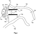
- Fig. 2 shows a schematic sectional view of an ear canal earpiece according to a first embodiment.
- the earpiece 100 has an electroacoustic reproduction transducer 110, a first sound guide unit 120, a second sound guide unit 130 and a third sound guide unit 140.
- the first sound guide unit 120 is provided in the area of a volume in front of a membrane of the electroacoustic reproduction transducer 110.
- the third sound guide unit 140 is designed as an ear mold or as an otoplastic. Its outer contour is adapted to the inner contour of an ear canal.
- the second sound guide unit 130 is used to extend the first sound guide unit 120.
- the second sound guide unit can be designed to be cylindrical.
- the length and diameter of the sound guide of the second sound guide unit 130 is designed in such a way that the acoustic mass of the first and second sound guide units 120, 130 together with the volume in front of the membrane of the reproduction transducer 110 generate a resonance frequency that expands the frequency response by the desired components.
- the first sound guide unit 120 has a first end 121 and a second end 122.
- the second end 122 is arranged on the side facing the ear, while the first end 121 is provided on the side facing away from the ear and can accommodate the electroacoustic reproduction transducer 110.
- the second sound guide unit 130 has a first end 131 on the side facing away from the ear and a second end 132 on the side facing towards the ear.
- the third sound guide unit has a first end 141 on the side facing away from the ear and a second end 142 on the side facing towards the ear.
- the second sound guide unit 130 has a baffle 150 in order to provide a clearly delimited acoustic closure.
- the baffle 150 is acoustically designed to be essentially tight.
- the front of the electroacoustic transducer is acoustically separated from the rear of the transducer by the acoustically essentially tight baffle 150.
- the baffle 150 can also be configured as part of the third sound guide unit 140 or as a separate part and can be inserted into a first end 141 of the third sound guide unit 140.
- the baffle 150 is provided in an inner volume 143 of the third sound guide unit 140 in the area of the first end 141.
- the baffle 150 terminates with the first and second ends 131, 132 of the second sound guide unit 130.
- the third sound guide unit 140 has a cross section or inner diameter which is larger than the cross section or the inner diameter of the second sound guide unit 130.
- the outer contour of the third sound guide unit 140 is essentially adapted to the inner contour of the ear canal.
- the thickness of the third sound guide unit 140 is made as thin as possible.
- a compromise must be chosen between the smallest possible thickness of the third sound guide unit 140 with regard to the acoustics on the one hand and a minimum wall thickness in order to provide a certain mechanical stability of the third sound guide unit 140 on the other hand.
- the third sound guide unit 140 preferably has no constriction with regard to the geometry of the ear canal.
- the outer contour of the third sound guide unit 140 largely follows the inner contour of the user's ear canal.
- the ratio of the acoustically effective cross-sectional area compared to the total cross-sectional area of the outer contour is greater than 40% everywhere.
- the second and third sound guide units 130, 140 are designed to be removable from the transducer 110 and the first sound guide unit 120.
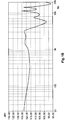
- Fig. 3 shows a frequency response of an arrangement of an ear canal and a receiver according to the first embodiment. Compared to the frequency response of Figure 1B a significant improvement can be seen, especially in the frequency range between 3 kHz and 10 kHz, because the breakdown in this frequency range can be avoided with a receiver according to the invention. At most there is still a resonance peak at 6 kHz.
- Fig. 4 shows a schematic sectional view of an ear canal earpiece according to a second embodiment.
- the ear canal receiver according to the second exemplary embodiment corresponds essentially to the ear canal receiver according to the first exemplary embodiment from FIG Fig. 2 .
- the baffle 150 according to the first embodiment is essentially flush with the second sound guide unit 130 (ie with its first and second ends 131, 132), the baffle 150 according to the second embodiment is set back further in the direction of the first end 141 of the third sound guide unit 140 .
- the baffle 150 can optionally be part of the third sound guide unit 140.
- the baffle can be installed or glued in as a separate component.
- the baffle can be produced by introducing adhesive.
- the second sound guide unit 130 does not have to be of cylindrical design either.
- An oval cross-section or a transition from an oval to a round cross-section or vice versa is also possible.
- the second sound guide unit 130 can also be designed as a funnel.
- cerumen filters In front of the openings, which have to be replaced regularly. But even if the cerumen is caught in the filter, the frequency response already changes.
- the opening facing the ear canal is so large that on the one hand cerumen that penetrates there has practically no influence on the acoustics and on the other hand the cerumen cannot get stuck there and practically falls out again when moving.
- FIG. 5A shows a schematic sectional view of an ear canal earpiece according to a third embodiment.
- the ear canal receiver according to the third exemplary embodiment corresponds essentially to the ear canal receiver according to the first exemplary embodiment from FIG Fig. 2 .
- the ear canal earpiece 100 thus has an electroacoustic reproduction transducer 110, a first, second and third sound guide unit 120, 130 and 140 and a sound wall 150 in the region of the second sound guide unit 130.
- the receiver has a ⁇ / 4 resonator 160 in the area of the baffle 150.
- the ⁇ / 4 resonator 160 has a first open end 161 on a side facing the ear and a closed end 162 on the side facing away from the ear.
- the closed end 162 can optionally extend beyond the baffle 150.
- the open end 161 can optionally extend beyond the baffle 150.
- the length of the resonator is determined by the wavelength of the frequency to be reduced.
- the Helmholtz resonator acts as an acoustic suction circuit and thus reduces the sound pressure in the ear canal in the area of the Helmholtz resonance.
- Figure 5B shows the frequency response 700 of Fig. 3 as a dashed line.
- the solid line shows the frequency response 800 smoothed in the range around 6 kHz according to the third exemplary embodiment.
- the diameter and the shape of the cross section of the resonator 160 determine the quality of the reduction effect.
- the cross section of the resonator 160 can be round, oval, angular, etc.
- the cross-section does not have to be constant over the length.
- the resonator 160 does not have to be straight, but can also be curved or shaped as desired.
- One or more acoustic resistors can be arranged in the resonator 160.
- acoustic suction circuits i. H. Resonators 160 are used according to the invention, which are then preferably tuned to different frequencies.
- Fig. 6 shows a schematic sectional view of an ear canal earpiece according to a fourth embodiment.
- the ear canal earpiece according to the fourth exemplary embodiment can be based on an ear canal earpiece according to the first or second exemplary embodiment.
- the ear canal receiver 100 thus has an electroacoustic sound transducer 110, a first, second and third sound guide unit 120, 130, 140 and a sound wall 150 in the region of the second sound guide unit 130.
- the receiver according to the fourth exemplary embodiment has a Helmholtz resonator 170 in the area of the baffle 150.
- the Helmholtz resonator 170 has a first open end 171 on the side facing the ear and a volume 172 in the region of the side facing away from the ear.
- a Helmholtz resonator consists of an element 173, which primarily forms an acoustic mass, and a closed volume 172. This is tuned in such a way that the Helmholtz resonance corresponds to the interfering resonance.
- the Helmholtz resonator acts as an acoustic suction circuit and thus reduces the sound pressure in the ear canal in the area of the Helmholtz resonance.
- an in Figure 5B shown improved frequency response can be achieved.
- the baffle 150 can end flush with the second sound guide unit 130.
- the second sound guide unit 130 can protrude beyond the sound wall in the direction of the side facing the ear, as has been described, for example, in accordance with the second exemplary embodiment.
- the design of the ear mold or the otoplastic enables the receiver to be placed further into the ear canal of a user, so that a relatively small electroacoustic sound transducer 110 can be used, which can be placed further into the ear canal can.
- the volume 172 of the Helmholtz resonator 170 can be led out of the sound wall 150 and can, for example, be placed next to or behind the electroacoustic sound transducer 110.
- openings can be provided in the first, second and third sound guide units, through which attenuation can be set.
- the electroacoustic sound transducer can be designed as a dynamic or magnetic sound transducer.
- the third sound guide unit 140 can be designed as an ear mold. Furthermore, the sound guide units can be designed as part of an otoplastic.
- Fig. 7 shows a schematic sectional view of an ear canal earpiece according to a fifth embodiment.
- the handset according to the fifth embodiment can be based on a handset according to the first, second, third or fourth embodiment.
- the receiver is realized as an ear-adapted ear canal receiver, ie the receiver can be built into an otoplastic.
- Fig. 8 shows a schematic sectional view of an ear canal earpiece according to a sixth embodiment.
- the listener according to the sixth exemplary embodiment can be based on a receiver according to the first, second, third or fourth exemplary embodiment.
- the ear pad on the receiver has been replaced by an ear mold.
- the ear mold can be designed as an otoplastic and pushed over the receiver.
- connection between the receiver and the earpiece is a connection that can be released again by the user, for example by means of a latching connection.
- damping elements can be provided in the first, second and third sound guide units in order to additionally influence the frequency response.
- the second and third sound guide unit can be designed as part of the receiver (for example as part of the otoplastic) or as an ear mold (ear mold unit).
Landscapes
- Engineering & Computer Science (AREA)
- Physics & Mathematics (AREA)
- Acoustics & Sound (AREA)
- Signal Processing (AREA)
- Health & Medical Sciences (AREA)
- Otolaryngology (AREA)
- Multimedia (AREA)
- Manufacturing & Machinery (AREA)
- General Health & Medical Sciences (AREA)
- Neurosurgery (AREA)
- Headphones And Earphones (AREA)
Claims (5)
- Ecouteur intra-auriculaire avecun transducteur électroacoustique (110),une première unité de guidage du son (120) pour guider le son depuis le transducteur électroacoustique (110), etune unité intra-auriculaire sur mesure, laquelle présente :une deuxième unité de guidage de son (130) pour prolonger la première unité de guidage de son (120), etune troisième unité de guidage de son (140), laquelle est configurée en tant qu'embout auriculaire, etentoure la deuxième unité de guidage de son (130) et est configurée pour poursuivre l'acheminement du son dans un canal intra-auriculaire d'un utilisateur, etdans lequel un contour extérieur de la troisième unité de guidage de son (140) est adapté à un contour intérieur du canal intra-auriculaire de l'utilisateur,une paroi acoustique (150) sensiblement acoustiquement étanche dans la zone de la deuxième unité de guidage de son (130), dans lequel la paroi acoustique (150) s'étend entre la deuxième et la troisième unité de guidage de son (130, 140) et forme une terminaison acoustique pour une zone acoustiquement active de la troisième unité de guidage de son (140) et sépare acoustiquement un côté avant d'un côté arrière du transducteur électroacoustique (110),dans lequel la paroi acoustique (150) est prévue sur une extrémité opposée à l'oreille (141) de la troisième unité de guidage de son (140),dans lequel l'unité intra-auriculaire sur mesure avec la deuxième et la troisième unité de guidage de son (130, 140) est configurée de manière à pouvoir être retirée de la première unité de guidage de son (120),dans lequel un diamètre intérieur de la troisième unité de guidage de son (140) est supérieur à un diamètre intérieur de la deuxième unité de guidage de son (130),dans lequel la troisième unité de guidage de son (140) présente une épaisseur de paroi inférieure pour agrandir la surface de section transversale acoustiquement active et une épaisseur de paroi minimale pour assurer une stabilité mécanique, dans lequel un rapport entre une surface de section transversale acoustiquement active et une surface de section transversale totale du contour extérieur de la troisième unité de guidage de son (140) est partout supérieur à 40 % dans la totalité de la zone acoustiquement active de la troisième unité de guidage de son (140).
- Ecouteur intra-auriculaire selon la revendication 1, dans lequella paroi acoustique (150) se termine par une première et une deuxième extrémité (130, 132) de la deuxième unité de guidage de son (130), oudans lequel une deuxième extrémité (132) de la deuxième unité de guidage de son (130) dépasse de la paroi acoustique (150).
- Ecouteur intra-auriculaire selon l'une quelconque des revendications 1 à 2, dans lequel
un résonateur λ/4 (160) est prévu dans la paroi acoustique (150). - Ecouteur intra-auriculaire selon l'une quelconque des revendications 1 à 3, dans lequel
un résonateur Helmholtz (170) est disposé au moins en partie dans la paroi acoustique (150). - Ecouteur intra-auriculaire selon la revendication 4, dans lequel
un volume (172) du résonateur Helmholtz (170) s'étend dans la zone du côté opposé à l'oreille de l'écouteur à l'extérieur de la paroi acoustique (150).
Applications Claiming Priority (2)
| Application Number | Priority Date | Filing Date | Title |
|---|---|---|---|
| DE102013205846.2A DE102013205846A1 (de) | 2013-04-03 | 2013-04-03 | Ohrkanal-Hörer und Ohrpass-Einheit für einen Hörer |
| PCT/EP2014/056596 WO2014161885A1 (fr) | 2013-04-03 | 2014-04-02 | Écouteur intra-auriculaire et ensemble embout auriculaire pour écouteur |
Publications (2)
| Publication Number | Publication Date |
|---|---|
| EP2982135A1 EP2982135A1 (fr) | 2016-02-10 |
| EP2982135B1 true EP2982135B1 (fr) | 2021-12-01 |
Family
ID=50424255
Family Applications (1)
| Application Number | Title | Priority Date | Filing Date |
|---|---|---|---|
| EP14714708.6A Active EP2982135B1 (fr) | 2013-04-03 | 2014-04-02 | Écouteur intra-auriculaire avec embout auriculaire sur mesure |
Country Status (4)
| Country | Link |
|---|---|
| US (1) | US9628925B2 (fr) |
| EP (1) | EP2982135B1 (fr) |
| DE (1) | DE102013205846A1 (fr) |
| WO (1) | WO2014161885A1 (fr) |
Families Citing this family (5)
| Publication number | Priority date | Publication date | Assignee | Title |
|---|---|---|---|---|
| KR102167420B1 (ko) | 2017-06-01 | 2020-10-20 | 주식회사 이엠텍 | 공명 프로텍터를 포함하는 이어폰용 다이나믹 리시버 |
| JP6400157B1 (ja) * | 2017-07-25 | 2018-10-03 | Ttr株式会社 | 密閉型イヤホン |
| CN111213390B (zh) * | 2017-10-11 | 2021-11-16 | 无线电广播技术研究所 | 声音转换器 |
| GB2586063B (en) * | 2019-08-01 | 2024-06-19 | Drown Ltd | Modular earphone |
| EP4518350A4 (fr) * | 2022-10-25 | 2025-07-16 | Shenzhen Shokz Co Ltd | Haut-parleur |
Citations (1)
| Publication number | Priority date | Publication date | Assignee | Title |
|---|---|---|---|---|
| US4870688A (en) * | 1986-05-27 | 1989-09-26 | Barry Voroba | Mass production auditory canal hearing aid |
Family Cites Families (11)
| Publication number | Priority date | Publication date | Assignee | Title |
|---|---|---|---|---|
| US2964596A (en) * | 1956-08-01 | 1960-12-13 | Zenith Radio Corp | Sound-reproducing device |
| US4006321A (en) | 1974-02-20 | 1977-02-01 | Industrial Research Products, Inc. | Transducer coupling system |
| US4311206A (en) * | 1978-05-15 | 1982-01-19 | Johnson Rubein V | Hearing aid ear mold with improved discrimination |
| US5195139A (en) * | 1991-05-15 | 1993-03-16 | Ensoniq Corporation | Hearing aid |
| DE19943809A1 (de) * | 1999-09-14 | 2001-03-15 | Acousticon Hoersyteme Gmbh | Hörgerät |
| WO2007089845A2 (fr) * | 2006-01-30 | 2007-08-09 | Etymotic Research, Inc. | Écouteur à embout utilisant un dispositif d'attaque de bobine mobile |
| JP4921197B2 (ja) * | 2007-02-06 | 2012-04-25 | スター精密株式会社 | 挿入型イヤホン |
| DE102008003248A1 (de) | 2008-01-04 | 2009-07-09 | Sennheiser Electronic Gmbh & Co. Kg | Hörer |
| US8391526B2 (en) | 2008-02-27 | 2013-03-05 | Linda D. Dahl | Ear device for improved fit and sound |
| WO2009140982A1 (fr) * | 2008-05-21 | 2009-11-26 | Phonak Ag | Système d’écouteur et son utilisation |
| DE102009008376A1 (de) | 2009-02-11 | 2010-08-12 | Sennheiser Electronic Gmbh & Co. Kg | Hörer |
-
2013
- 2013-04-03 DE DE102013205846.2A patent/DE102013205846A1/de active Pending
-
2014
- 2014-04-02 WO PCT/EP2014/056596 patent/WO2014161885A1/fr not_active Ceased
- 2014-04-02 US US14/782,143 patent/US9628925B2/en active Active
- 2014-04-02 EP EP14714708.6A patent/EP2982135B1/fr active Active
Patent Citations (1)
| Publication number | Priority date | Publication date | Assignee | Title |
|---|---|---|---|---|
| US4870688A (en) * | 1986-05-27 | 1989-09-26 | Barry Voroba | Mass production auditory canal hearing aid |
Also Published As
| Publication number | Publication date |
|---|---|
| US9628925B2 (en) | 2017-04-18 |
| US20160066111A1 (en) | 2016-03-03 |
| DE102013205846A8 (de) | 2014-11-27 |
| WO2014161885A1 (fr) | 2014-10-09 |
| EP2982135A1 (fr) | 2016-02-10 |
| DE102013205846A1 (de) | 2014-10-09 |
Similar Documents
| Publication | Publication Date | Title |
|---|---|---|
| EP2982135B1 (fr) | Écouteur intra-auriculaire avec embout auriculaire sur mesure | |
| DE102009040050B4 (de) | Ohrkanalhörer | |
| EP1499159B1 (fr) | Suppression active du bruit dans les prothèses auditives. | |
| DE102009008376A1 (de) | Hörer | |
| WO2009071570A2 (fr) | Écouteur | |
| DE102005036849A1 (de) | Hörerschlauch mit Dämpfungselement und entsprechende Hörvorrichtung | |
| DE102015204250A1 (de) | Hörgerät mit einer Cerumen-Schutzeinrichtung und Cerumen-Schutzeinrichtung | |
| DE102010004667A1 (de) | Gehäuse und Lautsprechermodul | |
| DE102014225923B4 (de) | Ohrkanal-Hörer | |
| DE4010372C2 (fr) | ||
| EP1929833A2 (fr) | Microcasque et ecouteur a placer dans l'oreille | |
| DE102005029514B4 (de) | Gehörschutzstöpsel | |
| EP2002685B1 (fr) | Casque ecouteur | |
| EP3643077B1 (fr) | Écouteur intra-auriculaire | |
| DE102013107512B4 (de) | Ohrhörer | |
| EP1906703A1 (fr) | Prothèse auditive dotée d'un dispositif de liaison | |
| DE102020201533A1 (de) | Vorrichtung zur schallwandlung mit einem akustischen filter | |
| DE19943809A1 (de) | Hörgerät | |
| DE102013001920B3 (de) | Lautsprecher-Ohrstück für ein Hörgerät | |
| DE102013111851A1 (de) | Otoplastik, Hörsystem sowie Verfahren zur Montage eines Hörsystems | |
| DE2151956A1 (de) | Aus zwei Schalenhaelften bestehender Fernsprech-Handapparat aus Kunststoff | |
| EP0458046A2 (fr) | Combiné pour poste téléphonique | |
| EP2088803B1 (fr) | Appareil auditif doté d'un amortisseur acoustique | |
| DE1177211C2 (de) | Elektrodynamischer Kopfhoerer | |
| DE102010011509A1 (de) | Selektiver- individueller Gehör- und Lärmschutz |
Legal Events
| Date | Code | Title | Description |
|---|---|---|---|
| PUAI | Public reference made under article 153(3) epc to a published international application that has entered the european phase |
Free format text: ORIGINAL CODE: 0009012 |
|
| 17P | Request for examination filed |
Effective date: 20151103 |
|
| AK | Designated contracting states |
Kind code of ref document: A1 Designated state(s): AL AT BE BG CH CY CZ DE DK EE ES FI FR GB GR HR HU IE IS IT LI LT LU LV MC MK MT NL NO PL PT RO RS SE SI SK SM TR |
|
| AX | Request for extension of the european patent |
Extension state: BA ME |
|
| DAX | Request for extension of the european patent (deleted) | ||
| STAA | Information on the status of an ep patent application or granted ep patent |
Free format text: STATUS: EXAMINATION IS IN PROGRESS |
|
| 17Q | First examination report despatched |
Effective date: 20181026 |
|
| GRAP | Despatch of communication of intention to grant a patent |
Free format text: ORIGINAL CODE: EPIDOSNIGR1 |
|
| STAA | Information on the status of an ep patent application or granted ep patent |
Free format text: STATUS: GRANT OF PATENT IS INTENDED |
|
| RIC1 | Information provided on ipc code assigned before grant |
Ipc: H04R 1/28 20060101AFI20210525BHEP Ipc: H04R 1/10 20060101ALI20210525BHEP Ipc: H04R 25/00 20060101ALI20210525BHEP |
|
| INTG | Intention to grant announced |
Effective date: 20210628 |
|
| GRAS | Grant fee paid |
Free format text: ORIGINAL CODE: EPIDOSNIGR3 |
|
| GRAA | (expected) grant |
Free format text: ORIGINAL CODE: 0009210 |
|
| STAA | Information on the status of an ep patent application or granted ep patent |
Free format text: STATUS: THE PATENT HAS BEEN GRANTED |
|
| AK | Designated contracting states |
Kind code of ref document: B1 Designated state(s): AL AT BE BG CH CY CZ DE DK EE ES FI FR GB GR HR HU IE IS IT LI LT LU LV MC MK MT NL NO PL PT RO RS SE SI SK SM TR |
|
| REG | Reference to a national code |
Ref country code: GB Ref legal event code: FG4D Free format text: NOT ENGLISH |
|
| REG | Reference to a national code |
Ref country code: AT Ref legal event code: REF Ref document number: 1452919 Country of ref document: AT Kind code of ref document: T Effective date: 20211215 Ref country code: CH Ref legal event code: EP |
|
| REG | Reference to a national code |
Ref country code: IE Ref legal event code: FG4D Free format text: LANGUAGE OF EP DOCUMENT: GERMAN |
|
| REG | Reference to a national code |
Ref country code: DE Ref legal event code: R096 Ref document number: 502014016020 Country of ref document: DE |
|
| REG | Reference to a national code |
Ref country code: LT Ref legal event code: MG9D |
|
| REG | Reference to a national code |
Ref country code: NL Ref legal event code: MP Effective date: 20211201 |
|
| PG25 | Lapsed in a contracting state [announced via postgrant information from national office to epo] |
Ref country code: RS Free format text: LAPSE BECAUSE OF FAILURE TO SUBMIT A TRANSLATION OF THE DESCRIPTION OR TO PAY THE FEE WITHIN THE PRESCRIBED TIME-LIMIT Effective date: 20211201 Ref country code: LT Free format text: LAPSE BECAUSE OF FAILURE TO SUBMIT A TRANSLATION OF THE DESCRIPTION OR TO PAY THE FEE WITHIN THE PRESCRIBED TIME-LIMIT Effective date: 20211201 Ref country code: FI Free format text: LAPSE BECAUSE OF FAILURE TO SUBMIT A TRANSLATION OF THE DESCRIPTION OR TO PAY THE FEE WITHIN THE PRESCRIBED TIME-LIMIT Effective date: 20211201 Ref country code: BG Free format text: LAPSE BECAUSE OF FAILURE TO SUBMIT A TRANSLATION OF THE DESCRIPTION OR TO PAY THE FEE WITHIN THE PRESCRIBED TIME-LIMIT Effective date: 20220301 |
|
| PG25 | Lapsed in a contracting state [announced via postgrant information from national office to epo] |
Ref country code: SE Free format text: LAPSE BECAUSE OF FAILURE TO SUBMIT A TRANSLATION OF THE DESCRIPTION OR TO PAY THE FEE WITHIN THE PRESCRIBED TIME-LIMIT Effective date: 20211201 Ref country code: PL Free format text: LAPSE BECAUSE OF FAILURE TO SUBMIT A TRANSLATION OF THE DESCRIPTION OR TO PAY THE FEE WITHIN THE PRESCRIBED TIME-LIMIT Effective date: 20211201 Ref country code: NO Free format text: LAPSE BECAUSE OF FAILURE TO SUBMIT A TRANSLATION OF THE DESCRIPTION OR TO PAY THE FEE WITHIN THE PRESCRIBED TIME-LIMIT Effective date: 20220301 Ref country code: LV Free format text: LAPSE BECAUSE OF FAILURE TO SUBMIT A TRANSLATION OF THE DESCRIPTION OR TO PAY THE FEE WITHIN THE PRESCRIBED TIME-LIMIT Effective date: 20211201 Ref country code: HR Free format text: LAPSE BECAUSE OF FAILURE TO SUBMIT A TRANSLATION OF THE DESCRIPTION OR TO PAY THE FEE WITHIN THE PRESCRIBED TIME-LIMIT Effective date: 20211201 Ref country code: GR Free format text: LAPSE BECAUSE OF FAILURE TO SUBMIT A TRANSLATION OF THE DESCRIPTION OR TO PAY THE FEE WITHIN THE PRESCRIBED TIME-LIMIT Effective date: 20220302 Ref country code: ES Free format text: LAPSE BECAUSE OF FAILURE TO SUBMIT A TRANSLATION OF THE DESCRIPTION OR TO PAY THE FEE WITHIN THE PRESCRIBED TIME-LIMIT Effective date: 20211201 |
|
| PG25 | Lapsed in a contracting state [announced via postgrant information from national office to epo] |
Ref country code: NL Free format text: LAPSE BECAUSE OF FAILURE TO SUBMIT A TRANSLATION OF THE DESCRIPTION OR TO PAY THE FEE WITHIN THE PRESCRIBED TIME-LIMIT Effective date: 20211201 |
|
| PG25 | Lapsed in a contracting state [announced via postgrant information from national office to epo] |
Ref country code: SM Free format text: LAPSE BECAUSE OF FAILURE TO SUBMIT A TRANSLATION OF THE DESCRIPTION OR TO PAY THE FEE WITHIN THE PRESCRIBED TIME-LIMIT Effective date: 20211201 Ref country code: SK Free format text: LAPSE BECAUSE OF FAILURE TO SUBMIT A TRANSLATION OF THE DESCRIPTION OR TO PAY THE FEE WITHIN THE PRESCRIBED TIME-LIMIT Effective date: 20211201 Ref country code: RO Free format text: LAPSE BECAUSE OF FAILURE TO SUBMIT A TRANSLATION OF THE DESCRIPTION OR TO PAY THE FEE WITHIN THE PRESCRIBED TIME-LIMIT Effective date: 20211201 Ref country code: PT Free format text: LAPSE BECAUSE OF FAILURE TO SUBMIT A TRANSLATION OF THE DESCRIPTION OR TO PAY THE FEE WITHIN THE PRESCRIBED TIME-LIMIT Effective date: 20220401 Ref country code: EE Free format text: LAPSE BECAUSE OF FAILURE TO SUBMIT A TRANSLATION OF THE DESCRIPTION OR TO PAY THE FEE WITHIN THE PRESCRIBED TIME-LIMIT Effective date: 20211201 Ref country code: CZ Free format text: LAPSE BECAUSE OF FAILURE TO SUBMIT A TRANSLATION OF THE DESCRIPTION OR TO PAY THE FEE WITHIN THE PRESCRIBED TIME-LIMIT Effective date: 20211201 |
|
| REG | Reference to a national code |
Ref country code: DE Ref legal event code: R097 Ref document number: 502014016020 Country of ref document: DE |
|
| PG25 | Lapsed in a contracting state [announced via postgrant information from national office to epo] |
Ref country code: IS Free format text: LAPSE BECAUSE OF FAILURE TO SUBMIT A TRANSLATION OF THE DESCRIPTION OR TO PAY THE FEE WITHIN THE PRESCRIBED TIME-LIMIT Effective date: 20220401 |
|
| PLBE | No opposition filed within time limit |
Free format text: ORIGINAL CODE: 0009261 |
|
| STAA | Information on the status of an ep patent application or granted ep patent |
Free format text: STATUS: NO OPPOSITION FILED WITHIN TIME LIMIT |
|
| PG25 | Lapsed in a contracting state [announced via postgrant information from national office to epo] |
Ref country code: DK Free format text: LAPSE BECAUSE OF FAILURE TO SUBMIT A TRANSLATION OF THE DESCRIPTION OR TO PAY THE FEE WITHIN THE PRESCRIBED TIME-LIMIT Effective date: 20211201 Ref country code: AL Free format text: LAPSE BECAUSE OF FAILURE TO SUBMIT A TRANSLATION OF THE DESCRIPTION OR TO PAY THE FEE WITHIN THE PRESCRIBED TIME-LIMIT Effective date: 20211201 |
|
| 26N | No opposition filed |
Effective date: 20220902 |
|
| PG25 | Lapsed in a contracting state [announced via postgrant information from national office to epo] |
Ref country code: SI Free format text: LAPSE BECAUSE OF FAILURE TO SUBMIT A TRANSLATION OF THE DESCRIPTION OR TO PAY THE FEE WITHIN THE PRESCRIBED TIME-LIMIT Effective date: 20211201 |
|
| REG | Reference to a national code |
Ref country code: CH Ref legal event code: PL |
|
| REG | Reference to a national code |
Ref country code: BE Ref legal event code: MM Effective date: 20220430 |
|
| PG25 | Lapsed in a contracting state [announced via postgrant information from national office to epo] |
Ref country code: MC Free format text: LAPSE BECAUSE OF FAILURE TO SUBMIT A TRANSLATION OF THE DESCRIPTION OR TO PAY THE FEE WITHIN THE PRESCRIBED TIME-LIMIT Effective date: 20211201 Ref country code: LU Free format text: LAPSE BECAUSE OF NON-PAYMENT OF DUE FEES Effective date: 20220402 Ref country code: LI Free format text: LAPSE BECAUSE OF NON-PAYMENT OF DUE FEES Effective date: 20220430 Ref country code: CH Free format text: LAPSE BECAUSE OF NON-PAYMENT OF DUE FEES Effective date: 20220430 |
|
| PG25 | Lapsed in a contracting state [announced via postgrant information from national office to epo] |
Ref country code: BE Free format text: LAPSE BECAUSE OF NON-PAYMENT OF DUE FEES Effective date: 20220430 |
|
| PG25 | Lapsed in a contracting state [announced via postgrant information from national office to epo] |
Ref country code: IE Free format text: LAPSE BECAUSE OF NON-PAYMENT OF DUE FEES Effective date: 20220402 |
|
| PG25 | Lapsed in a contracting state [announced via postgrant information from national office to epo] |
Ref country code: IT Free format text: LAPSE BECAUSE OF FAILURE TO SUBMIT A TRANSLATION OF THE DESCRIPTION OR TO PAY THE FEE WITHIN THE PRESCRIBED TIME-LIMIT Effective date: 20211201 |
|
| REG | Reference to a national code |
Ref country code: AT Ref legal event code: MM01 Ref document number: 1452919 Country of ref document: AT Kind code of ref document: T Effective date: 20220402 |
|
| PG25 | Lapsed in a contracting state [announced via postgrant information from national office to epo] |
Ref country code: AT Free format text: LAPSE BECAUSE OF NON-PAYMENT OF DUE FEES Effective date: 20220402 |
|
| PG25 | Lapsed in a contracting state [announced via postgrant information from national office to epo] |
Ref country code: HU Free format text: LAPSE BECAUSE OF FAILURE TO SUBMIT A TRANSLATION OF THE DESCRIPTION OR TO PAY THE FEE WITHIN THE PRESCRIBED TIME-LIMIT; INVALID AB INITIO Effective date: 20140402 |
|
| PG25 | Lapsed in a contracting state [announced via postgrant information from national office to epo] |
Ref country code: MK Free format text: LAPSE BECAUSE OF FAILURE TO SUBMIT A TRANSLATION OF THE DESCRIPTION OR TO PAY THE FEE WITHIN THE PRESCRIBED TIME-LIMIT Effective date: 20211201 Ref country code: CY Free format text: LAPSE BECAUSE OF FAILURE TO SUBMIT A TRANSLATION OF THE DESCRIPTION OR TO PAY THE FEE WITHIN THE PRESCRIBED TIME-LIMIT Effective date: 20211201 |
|
| REG | Reference to a national code |
Ref country code: DE Ref legal event code: R081 Ref document number: 502014016020 Country of ref document: DE Owner name: SENNHEISER ELECTRONIC SE & CO. KG, DE Free format text: FORMER OWNER: SENNHEISER ELECTRONIC GMBH & CO. KG, 30900 WEDEMARK, DE |
|
| PG25 | Lapsed in a contracting state [announced via postgrant information from national office to epo] |
Ref country code: TR Free format text: LAPSE BECAUSE OF FAILURE TO SUBMIT A TRANSLATION OF THE DESCRIPTION OR TO PAY THE FEE WITHIN THE PRESCRIBED TIME-LIMIT Effective date: 20211201 |
|
| PG25 | Lapsed in a contracting state [announced via postgrant information from national office to epo] |
Ref country code: MT Free format text: LAPSE BECAUSE OF FAILURE TO SUBMIT A TRANSLATION OF THE DESCRIPTION OR TO PAY THE FEE WITHIN THE PRESCRIBED TIME-LIMIT Effective date: 20211201 |
|
| PGFP | Annual fee paid to national office [announced via postgrant information from national office to epo] |
Ref country code: DE Payment date: 20250409 Year of fee payment: 12 |
|
| PGFP | Annual fee paid to national office [announced via postgrant information from national office to epo] |
Ref country code: FR Payment date: 20250422 Year of fee payment: 12 |
|
| PGFP | Annual fee paid to national office [announced via postgrant information from national office to epo] |
Ref country code: GB Payment date: 20260324 Year of fee payment: 13 |