EP2982334A1 - Dispositif d'accouplement destiné à la transmission d'un mouvement d'entraînement d'une pièce à main transmettant des vibrations à un outil médical, en particulier dentaire - Google Patents
Dispositif d'accouplement destiné à la transmission d'un mouvement d'entraînement d'une pièce à main transmettant des vibrations à un outil médical, en particulier dentaire Download PDFInfo
- Publication number
- EP2982334A1 EP2982334A1 EP14180304.9A EP14180304A EP2982334A1 EP 2982334 A1 EP2982334 A1 EP 2982334A1 EP 14180304 A EP14180304 A EP 14180304A EP 2982334 A1 EP2982334 A1 EP 2982334A1
- Authority
- EP
- European Patent Office
- Prior art keywords
- coupling
- projection
- elements
- recess
- coupling elements
- Prior art date
- Legal status (The legal status is an assumption and is not a legal conclusion. Google has not performed a legal analysis and makes no representation as to the accuracy of the status listed.)
- Granted
Links
Images
Classifications
-
- A—HUMAN NECESSITIES
- A61—MEDICAL OR VETERINARY SCIENCE; HYGIENE
- A61C—DENTISTRY; APPARATUS OR METHODS FOR ORAL OR DENTAL HYGIENE
- A61C1/00—Dental machines for boring or cutting ; General features of dental machines or apparatus, e.g. hand-piece design
- A61C1/08—Machine parts specially adapted for dentistry
- A61C1/14—Tool-holders, i.e. operating tool holders, e.g. burr holders
- A61C1/148—Non-rotating tool holders, e.g. vibrating, oscillating, nutating
-
- A—HUMAN NECESSITIES
- A61—MEDICAL OR VETERINARY SCIENCE; HYGIENE
- A61C—DENTISTRY; APPARATUS OR METHODS FOR ORAL OR DENTAL HYGIENE
- A61C1/00—Dental machines for boring or cutting ; General features of dental machines or apparatus, e.g. hand-piece design
- A61C1/0061—Air and water supply systems; Valves specially adapted therefor
-
- A—HUMAN NECESSITIES
- A61—MEDICAL OR VETERINARY SCIENCE; HYGIENE
- A61C—DENTISTRY; APPARATUS OR METHODS FOR ORAL OR DENTAL HYGIENE
- A61C1/00—Dental machines for boring or cutting ; General features of dental machines or apparatus, e.g. hand-piece design
- A61C1/02—Dental machines for boring or cutting ; General features of dental machines or apparatus, e.g. hand-piece design characterised by the drive of the dental tools
- A61C1/07—Dental machines for boring or cutting ; General features of dental machines or apparatus, e.g. hand-piece design characterised by the drive of the dental tools with vibratory drive, e.g. ultrasonic waves
-
- A—HUMAN NECESSITIES
- A61—MEDICAL OR VETERINARY SCIENCE; HYGIENE
- A61C—DENTISTRY; APPARATUS OR METHODS FOR ORAL OR DENTAL HYGIENE
- A61C17/00—Devices for cleaning, polishing, rinsing or drying teeth, teeth cavities or prostheses; Saliva removers; Dental appliances for receiving spittle
- A61C17/16—Power-driven cleaning or polishing devices
- A61C17/20—Power-driven cleaning or polishing devices using ultrasonic waves
Definitions
- Such coupling devices are used to attach a medical tool, which is designed in particular for removing tartar, to a handpiece which has a vibration source.
- the vibration source is in this case preferably designed as a piezo drive and activates the tool by means of sound or ultrasound.
- Such a coupling device for a medical handpiece and tool is in particular from the EP 2 160 997 A1 known.
- This coupling device for releasably connecting a tool with a medical handpiece comprises a first coupling element provided on the tool and a second coupling element arranged on the handpiece. Both coupling elements are connected by means of a ball-race connection and a contact surface for frictional connection with each other to ensure a tight fit. Only by a firm connection of the tool with the vibration source, a transfer of the vibration energy can be applied to the tool.
- the ball raceway connection in this case has a substantially helically around the longitudinal axis of the coupling device extending guide groove, into which engages a guide element of the other coupling element.
- the contact surface for the frictional connection is preferably formed by a conical contact surface on the tool and a complementary contact surface on the handpiece.
- the first portion for releasably connecting the two coupling elements is formed by a screw connection, preferably by a multi-start thread.
- the second portion preferably has a cylindrical guide surface on the coupling projection and in the coupling recess.
- the coupling device of the first portion for releasably connecting the two coupling elements is arranged in front of the second portion at the front end of the lateral surface of the coupling projection and at the rear end of the lateral surface of the coupling recess.
- the coupling projection has a chamfer at its front end.
- the diameter of the first section on the coupling projection and on the coupling recess is smaller than the diameter of the second section on the coupling projection and on the coupling recess.
- the length of the first section on the coupling projection is preferably smaller than the length of the second section on the coupling recess, so that both coupling elements are guided by the second section to each other and slidable along the common axis of rotation, before the two coupling elements by means of the first portion with each other are connectable.
- the second portion on the coupling projection preferably has a groove-shaped recess.
- At least one of the two coupling elements is at least partially made of titanium. Furthermore, at least one of the two coupling elements is preferably at least partially provided with a wear-resistant coating.
- both coupling elements preferably have a fluid channel, so that a working medium can be fed to the tool. Furthermore, both coupling elements preferably have a stop surface, so that both coupling elements can be clamped together in the axial direction to the common axis of rotation.
- one support region in particular in the form of a polygon, is preferably provided on one of the two coupling elements for applying a tool wrench.
- the present coupling device is characterized by the following advantages.
- both coupling elements of the coupling device which serves both coupling elements to position their common axis of rotation and both coupling elements guided to each other and slidably supported along the common axis of rotation, before the Both coupling elements are releasably connected to each other by means of another section, a faulty connection between the tool and the handpiece is avoided.
- an improper insertion of the external thread into the internal thread is avoided in the formation of the further section as a screw with an internal and external thread by the targeted guidance of the two coupling elements to each other.
- the coupling device according to the invention ensures the user a simple and time-saving attachment of the tool with the handpiece. Repeated application of the first coupling element to the second coupling element in order to preferably insert an external thread of the one coupling element into the internal thread of the second coupling element is no longer necessary.
- the coupling device is not limited to vibration-transmitting handpieces with a vibration source for the preparation of surfaces of teeth. Rather, such coupling devices can also be used with other powered medical handpieces, such as with rotary driven handpieces.
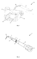
- FIG. 1 a medical, in particular dental, treatment device 29 with a vibration-transmitting handpiece 2 and a medical, in particular dental, tool 3 is shown.
- a vibration source is arranged, which is preferably designed as a piezo drive.
- the tool 3 is preferably detachably connected directly to the drive shaft of the piezo drive by means of the coupling device, so that the tool 3 can be activated by means of sound or ultrasound.
- a supply hose 30 serves to connect the handpiece 2, in particular its drive, with the control unit 31. During operation of the handpiece 2 this and the tool 3 with working media, in particular with electrical energy and spray water to cool the tool to supply.
- the supply hose 30 serves in particular to transmit electrical signals and / or data between the control unit 31 and the handpiece 2.
- the control unit 31 has at least one display 32 and at least one actuating element 33.
- a connectable to the control unit 31 container 34 serves as a source of fluid for the spray water for cooling the handpiece 2 and / or the tool.
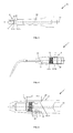
- FIG. 2 shows the coupling device 1 according to the invention with a first on a drive shaft 28 of the handpiece 2 and a second provided on the tool 3 coupling element 4, 5.
- the tool 2 shown for surface treatment of teeth comprises a tool shank to which a working head 35 is mounted.
- the working head 35 can have a wide variety of shapes.
- the coupling element 5 is arranged to releasably attach the tool 3 to the other coupling element 4, which is preferably connected to the drive shaft 28 of the handpiece 2.
- the coupling element 4 on the drive axle 28 is in this case preferably designed as a coupling projection 6, which is insertable into a coupling recess 6 of the other coupling element 5.
- FIG. 3 is the drive shaft 28 of the handpiece 2 with the coupling projection 4 formed as a coupling element 4 of the coupling device 1 shown.
- the first section 8 on the coupling projection 6 for releasably connecting the two coupling elements 4, 5 is in this embodiment by a Screw connection 13 is formed, which preferably comprises a multi-start thread.
- the drive shaft 28 with the coupling element 4 is preferably made of titanium and has a wear-resistant coating at least in the region of the screw connection.
- the second portion 10 for positioning the two coupling elements 4, 5 to each other is formed by a cylindrical guide surface 15 on the coupling projection 6, which extends along the axis of rotation 12.
- the first section 8 is in this case arranged in front of the second section 10 at the front end 17 of the coupling projection 6.
- the coupling projection 6 has a chamfer 21 at its front end 17.
- the diameter A of the first section 8 is on the coupling projection 6 smaller than the diameter B of the second portion 10 is formed.
- the coupling element 4 On the base surface of the drive shaft 28, from which the coupling projection 6 extends, the coupling element 4 has a stop face 23.
- the abutment surface 23 preferably extends in the radial direction about the coupling projection 6.
- the abutment surfaces 23 are also preferably provided with a wear-resistant coating.
- the corresponding coupling element 5 on the tool 3 also has a stop surface 24, so that both coupling elements 4, 5 by means of the first section 8, 9, in particular by means of the screw 13, 14, in the axial direction to the common axis of rotation 12 are braced together.
- the fluid channel 25 in the drive shaft 28 extends in this embodiment along the common axis of rotation 12 through the coupling element 4, in particular by the coupling projection 6 with the first and second portions 8, 10 to the free end 17 of the coupling projection.
- FIG. 4 The first portion 9 for releasably connecting the two coupling elements 4, 5 is formed by a screw 14 having an internal thread, which is connectable to the external thread 13 on the coupling projection 6 ,
- the first section 9 is arranged here at the rear end 18 of the coupling recess 7.
- the second section 11 in the coupling recess 7 for positioning the two coupling elements 4, 5 to each other is also by a cylindrical Guide surface 16 is formed, which extends in the axial direction to the common axis of rotation 12.
- coupling projection 6 in the coupling recess 7 and the diameter A 'of the first portion 9 is smaller than the diameter B' of the second portion 11 is formed.
- Both coupling elements 4, 5 are so guided by means of the second portion 10, 11 to each other in one another before they can be braced by means of the first portion 8, 9 and the stop surfaces 23, 24 with each other.
- the fluid channel 26 in the tool 3 can be connected to the fluid channel 25 of the drive axle by means of the coupling device 1.
- FIG. 5 is a detailed view of the coupling device 1 shown, in which the tool 3 and the handpiece 2, in particular the first coupling element 4 with the second coupling element 5, is firmly connected.
- This fixed and detachable connection is achieved in that both coupling elements 4, 5 are first positioned to the common axis of rotation 12, in which the coupling projection 6 is inserted with the lateral surface 19 in the coupling recess 7 with the lateral surface 20 until the second portion 10 of the coupling projection 6 is at least partially disposed in the second portion 11 of the coupling recess 7.
- both coupling elements 4, 5 guided to each other and moved along the common axis of rotation 12 until the first portion 8 of the coupling projection 6 engages at least partially in the first portion 9 of the coupling recess 7. Finally, both coupling elements 4, 5 are screwed together by means of the screw connection to the first section 8, 9 and firmly clamped by means of the stop surfaces 23, 24 against each other.
- a constriction 22 in the lateral surface 19 of the coupling projection 6 serves to relieve in the transmission of a drive movement of the handpiece 2 on the tool 3, the first portion 8 on the coupling projection 6, in particular the screw with the inner and outer threads.
- the lengths L, L 'and K, K' of the first section 8, 9 and the second section 10, 11 on the coupling projection 6 and the coupling recess 7 are in this case selected such that both coupling elements 4, 5 guided to each other and along the common axis of rotation 12 are slidable before they are detachably connected to each other by means of the first section 8, 9.
- the length L of the first portion 8 on the coupling projection 6 is smaller than the length K 'of the second portion 11 in the coupling recess 7, so that the second portion 10 of the coupling projection 6 engages in the coupling recess 7, before the first portion 8 of Coupling projection 6 in the first portion 9 of the coupling recess is insertable.
- the length K of the second portion 10 at the Coupling projection 6 and the length K 'of the second portion 11 on the coupling recess 7 are hereby selected to be as large as possible, so that due to the overlap of the two sections 10, 11 an exact positioning and guiding of the two coupling elements 4, 5 can be done to each other.
- the invention is not limited to the described embodiments, but includes all embodiments that apply or include the principle, analogous principle of operation of the invention. Furthermore, all features of all described and illustrated embodiments can be combined.
Landscapes
- Health & Medical Sciences (AREA)
- Oral & Maxillofacial Surgery (AREA)
- Dentistry (AREA)
- Epidemiology (AREA)
- Life Sciences & Earth Sciences (AREA)
- Animal Behavior & Ethology (AREA)
- General Health & Medical Sciences (AREA)
- Public Health (AREA)
- Veterinary Medicine (AREA)
- Engineering & Computer Science (AREA)
- Water Supply & Treatment (AREA)
- Dental Tools And Instruments Or Auxiliary Dental Instruments (AREA)
Priority Applications (7)
| Application Number | Priority Date | Filing Date | Title |
|---|---|---|---|
| ES14180304.9T ES2623140T3 (es) | 2014-08-08 | 2014-08-08 | Dispositivo de acoplamiento para transmitir un movimiento de impulsión de una pieza de mano, que transmite vibraciones, a una herramienta para uso clínico, particularmente odontológica |
| EP14180304.9A EP2982334B1 (fr) | 2014-08-08 | 2014-08-08 | Dispositif d'accouplement destiné à la transmission d'un mouvement d'entraînement d'une pièce à main transmettant des vibrations à un outil médical, en particulier dentaire |
| PL14180304T PL2982334T3 (pl) | 2014-08-08 | 2014-08-08 | Urządzenie sprzęgające do przenoszenia ruchu napędowego z elementu ręcznego przenoszącego drgania na narzędzie medyczne, w szczególności dentystyczne |
| JP2015157282A JP2016036741A (ja) | 2014-08-08 | 2015-08-07 | 振動伝達ハンドピースからの駆動運動を医療用、特に歯科用器具に伝達する結合装置 |
| US14/821,404 US20160038257A1 (en) | 2014-08-08 | 2015-08-07 | Coupling device for transferring a driving movement from a vibration transferring handpiece to a medical or dental tool |
| US15/296,219 US10828129B2 (en) | 2014-08-08 | 2016-10-18 | Tool-coupling device for a vibration transferring handpiece |
| JP2018094736A JP6955472B2 (ja) | 2014-08-08 | 2018-05-16 | 振動伝達ハンドピースからの駆動運動を医療用、特に歯科用器具に伝達する結合装置 |
Applications Claiming Priority (1)
| Application Number | Priority Date | Filing Date | Title |
|---|---|---|---|
| EP14180304.9A EP2982334B1 (fr) | 2014-08-08 | 2014-08-08 | Dispositif d'accouplement destiné à la transmission d'un mouvement d'entraînement d'une pièce à main transmettant des vibrations à un outil médical, en particulier dentaire |
Publications (2)
| Publication Number | Publication Date |
|---|---|
| EP2982334A1 true EP2982334A1 (fr) | 2016-02-10 |
| EP2982334B1 EP2982334B1 (fr) | 2017-02-01 |
Family
ID=51300585
Family Applications (1)
| Application Number | Title | Priority Date | Filing Date |
|---|---|---|---|
| EP14180304.9A Active EP2982334B1 (fr) | 2014-08-08 | 2014-08-08 | Dispositif d'accouplement destiné à la transmission d'un mouvement d'entraînement d'une pièce à main transmettant des vibrations à un outil médical, en particulier dentaire |
Country Status (5)
| Country | Link |
|---|---|
| US (1) | US20160038257A1 (fr) |
| EP (1) | EP2982334B1 (fr) |
| JP (2) | JP2016036741A (fr) |
| ES (1) | ES2623140T3 (fr) |
| PL (1) | PL2982334T3 (fr) |
Cited By (1)
| Publication number | Priority date | Publication date | Assignee | Title |
|---|---|---|---|---|
| EP3284435A1 (fr) * | 2016-08-18 | 2018-02-21 | W & H Dentalwerk Bürmoos GmbH | Dispositif d'accouplement d'outil pour un porte-outils transmettant des vibrations |
Families Citing this family (7)
| Publication number | Priority date | Publication date | Assignee | Title |
|---|---|---|---|---|
| USD768862S1 (en) * | 2015-06-18 | 2016-10-11 | Dentsply International, Inc. | Dental scaler with display |
| USD770626S1 (en) * | 2015-06-18 | 2016-11-01 | Dentsply International, Inc. | Display for dental scaler |
| US20170079754A1 (en) * | 2015-09-22 | 2017-03-23 | Kreigh SEDILLO | Apparatus for tooth stain removal |
| CN107951580B (zh) * | 2016-10-14 | 2020-07-28 | W和H牙科产品比莫斯有限公司 | 联接装置及振动传递手持件 |
| USD956241S1 (en) * | 2019-03-14 | 2022-06-28 | Light Instruments Ltd. | Laser delivery system |
| USD1035007S1 (en) * | 2022-05-20 | 2024-07-09 | Guilin Woodpecker Medical Instrument Co., Ltd. | Dental instrument |
| USD1041013S1 (en) * | 2022-10-13 | 2024-09-03 | Saeyang Co. Ltd. | Dental handpiece controller |
Citations (4)
| Publication number | Priority date | Publication date | Assignee | Title |
|---|---|---|---|---|
| EP0293654A2 (fr) * | 1987-06-03 | 1988-12-07 | Mikrona Technologie Ag | Appareil à détartrer les dents |
| EP1728483A1 (fr) * | 2005-05-30 | 2006-12-06 | Kaltenbach & Voigt GmbH | Pièce à main avec revêtement pour parties mobiles |
| DE102005058879A1 (de) * | 2005-12-09 | 2007-06-14 | Gebr. Brasseler Gmbh & Co. Kg | Schallaktivierbares Dentalinstrument |
| EP2160997A1 (fr) | 2008-09-04 | 2010-03-10 | W & H Dentalwerk Bürmoos GmbH | Dispositif d'embrayage destiné à l'utilisation avec une pièce à main médicale, en particulier à transmission de vibrations |
Family Cites Families (12)
| Publication number | Priority date | Publication date | Assignee | Title |
|---|---|---|---|---|
| DE2256059B2 (de) * | 1972-11-15 | 1977-10-06 | Kaitenbach & Voigt GmbH & Co, 7950 Biberach | Zahnaerztliches hand- oder winkelstueck |
| EP0642770B1 (fr) * | 1993-07-30 | 1999-10-06 | Kaltenbach & Voigt Gmbh & Co. | Pièce à main contre-angle ou droite avec dispositif de serrage détachable pour un outil, en particulier pour des fins médicales |
| US5801110A (en) * | 1997-04-07 | 1998-09-01 | Miltex Instrument Company | Ceramic composition for coating surgical and dental instruments |
| DE19947325A1 (de) * | 1999-10-01 | 2001-04-05 | Kaltenbach & Voigt | Durch eine Schraubverbindung zu verbindende Teile, insbesondere eines medizinischen Instrumentes |
| US6811399B2 (en) * | 2001-07-27 | 2004-11-02 | Hu-Friedy Mfg. Co., Inc. | Torque lock for ultrasonic swivelable inserts and method |
| US20060234185A1 (en) * | 2005-02-17 | 2006-10-19 | Discus Dental Impressions Inc. | Ultrasonic dental tool having a light source |
| ITBO20050097A1 (it) * | 2005-02-24 | 2006-08-25 | Italia Medica S R L | Manipolo per apparecchiature eletromedicali ad ultrasuoni |
| EP1747766B1 (fr) * | 2005-07-25 | 2010-10-13 | Deldent Ltd. | Appareil dentaire à ultrasons avec pièce à main adaptable |
| DE102007004808A1 (de) * | 2007-01-31 | 2008-08-07 | Kaltenbach & Voigt Gmbh | Zahnärztliches Behandlungsinstrument mit Kopplungseinrichtung zur Bewegungsübertragung und lösbaren Befestigung eines Behandlungswerkzeugs |
| DE102008014667A1 (de) * | 2008-03-18 | 2009-10-22 | Ferton Holding S.A. | Befestigungssystem |
| FR2957243B1 (fr) * | 2010-03-12 | 2012-04-13 | Conception Des Applic Des Tech Electroniques Soc Pour | Instrument vibratoire a outil interchangeable |
| DE102011010897B4 (de) * | 2011-02-10 | 2023-02-09 | Gebr. Brasseler Gmbh & Co. Kg | Dentalinstrument sowie Verfahren zu dessen Herstellung |
-
2014
- 2014-08-08 EP EP14180304.9A patent/EP2982334B1/fr active Active
- 2014-08-08 PL PL14180304T patent/PL2982334T3/pl unknown
- 2014-08-08 ES ES14180304.9T patent/ES2623140T3/es active Active
-
2015
- 2015-08-07 JP JP2015157282A patent/JP2016036741A/ja active Pending
- 2015-08-07 US US14/821,404 patent/US20160038257A1/en not_active Abandoned
-
2018
- 2018-05-16 JP JP2018094736A patent/JP6955472B2/ja active Active
Patent Citations (4)
| Publication number | Priority date | Publication date | Assignee | Title |
|---|---|---|---|---|
| EP0293654A2 (fr) * | 1987-06-03 | 1988-12-07 | Mikrona Technologie Ag | Appareil à détartrer les dents |
| EP1728483A1 (fr) * | 2005-05-30 | 2006-12-06 | Kaltenbach & Voigt GmbH | Pièce à main avec revêtement pour parties mobiles |
| DE102005058879A1 (de) * | 2005-12-09 | 2007-06-14 | Gebr. Brasseler Gmbh & Co. Kg | Schallaktivierbares Dentalinstrument |
| EP2160997A1 (fr) | 2008-09-04 | 2010-03-10 | W & H Dentalwerk Bürmoos GmbH | Dispositif d'embrayage destiné à l'utilisation avec une pièce à main médicale, en particulier à transmission de vibrations |
Cited By (1)
| Publication number | Priority date | Publication date | Assignee | Title |
|---|---|---|---|---|
| EP3284435A1 (fr) * | 2016-08-18 | 2018-02-21 | W & H Dentalwerk Bürmoos GmbH | Dispositif d'accouplement d'outil pour un porte-outils transmettant des vibrations |
Also Published As
| Publication number | Publication date |
|---|---|
| JP6955472B2 (ja) | 2021-10-27 |
| JP2016036741A (ja) | 2016-03-22 |
| JP2018149341A (ja) | 2018-09-27 |
| ES2623140T3 (es) | 2017-07-10 |
| EP2982334B1 (fr) | 2017-02-01 |
| PL2982334T3 (pl) | 2017-07-31 |
| US20160038257A1 (en) | 2016-02-11 |
Similar Documents
| Publication | Publication Date | Title |
|---|---|---|
| EP2982334B1 (fr) | Dispositif d'accouplement destiné à la transmission d'un mouvement d'entraînement d'une pièce à main transmettant des vibrations à un outil médical, en particulier dentaire | |
| DE2347624A1 (de) | Chirurgischer bohrer | |
| DE102009052482A1 (de) | Verfahren und Vorrichtung zur Herstellung von rohrförmigen Werkstücken aus einen vorgelochten Hohlblock | |
| EP2163220B1 (fr) | Système de guidage de forage médical dentaire | |
| EP3172002A1 (fr) | Logement d'outil destiné à relier une foreuse au diamant avec une couronne de forage | |
| EP2160997B1 (fr) | Dispositif de connection pour utiliser avec une pièce à main médicale, en particulier à transmission de vibrations | |
| DE102007004808A1 (de) | Zahnärztliches Behandlungsinstrument mit Kopplungseinrichtung zur Bewegungsübertragung und lösbaren Befestigung eines Behandlungswerkzeugs | |
| EP2522297B1 (fr) | Instrument manuel dentaire doté d'une poignée longitudinale | |
| EP2745797B1 (fr) | Outil de coupe à entraînement sonore | |
| EP2422738B1 (fr) | Instrument dentaire sonique et ultrasonique, dispositif de couplage de pointes soniques et outil à pointes soniques | |
| EP2444587A1 (fr) | Dispositif d'entraînement | |
| AT413330B (de) | Drehmomentübertragung für ein chirurgisches oder dentales, rotierendes werkzeug | |
| DE102004006930A1 (de) | Werkzeug zur Erweiterung eines in einem Knochen ausgebildeten Loches, insbesondere zum Einsetzen eines intraossären Zahnimplantates | |
| EP4422545B1 (fr) | Système de préparation et/ou de réalisation d'une insertion d'implant dentaire | |
| EP3284435B1 (fr) | Dispositif d'accouplement d'outil pour un porte-outils transmettant des vibrations | |
| EP3518814A1 (fr) | Instrument de traitement de dentisterie pour le fonctionnement d'un outil rotatif | |
| DE202014010694U1 (de) | Kupplungsvorrichtung zur Übertragung einer Antriebsbewegung von einem schwingungsübertragenden Handstück auf ein medizinisches, insbesondere zahnärztliches, Werkzeug | |
| DE19744856A1 (de) | Vorrichtung für die Mikrosondenchirurgie | |
| EP2995274B1 (fr) | Instrument dentaire à main et son boîtier de tête | |
| EP2165673B1 (fr) | Instrument dentaire à ultrasons | |
| EP1402997A2 (fr) | Moyens de blocage pour la prévention de la rotation non-voulue d'un axe ou d'une partie d'axe, en particulier pour des pièces à main médicales | |
| DE202015101895U1 (de) | Bohrhülsensatz und implantologisches Kit | |
| EP2910215B1 (fr) | Instrument manuel médical, en particulier dentaire | |
| EP1709933A2 (fr) | Pièce à main médicale avec axe formant un angle | |
| DE102006007232A1 (de) | Hinterschnittwerkzeug und Plateau-Bohrer |
Legal Events
| Date | Code | Title | Description |
|---|---|---|---|
| REG | Reference to a national code |
Ref country code: DE Ref legal event code: R138 Ref document number: 202014010694 Country of ref document: DE Free format text: GERMAN DOCUMENT NUMBER IS 502014002593 |
|
| PUAI | Public reference made under article 153(3) epc to a published international application that has entered the european phase |
Free format text: ORIGINAL CODE: 0009012 |
|
| 17P | Request for examination filed |
Effective date: 20151113 |
|
| AK | Designated contracting states |
Kind code of ref document: A1 Designated state(s): AL AT BE BG CH CY CZ DE DK EE ES FI FR GB GR HR HU IE IS IT LI LT LU LV MC MK MT NL NO PL PT RO RS SE SI SK SM TR |
|
| AX | Request for extension of the european patent |
Extension state: BA ME |
|
| REG | Reference to a national code |
Ref country code: DE Ref legal event code: R079 Ref document number: 502014002593 Country of ref document: DE Free format text: PREVIOUS MAIN CLASS: A61C0001140000 Ipc: A61C0017200000 |
|
| GRAP | Despatch of communication of intention to grant a patent |
Free format text: ORIGINAL CODE: EPIDOSNIGR1 |
|
| RIC1 | Information provided on ipc code assigned before grant |
Ipc: A61C 3/03 20060101ALI20161018BHEP Ipc: A61C 1/00 20060101ALI20161018BHEP Ipc: A61C 17/20 20060101AFI20161018BHEP Ipc: A61C 1/14 20060101ALI20161018BHEP Ipc: A61C 1/07 20060101ALI20161018BHEP |
|
| INTG | Intention to grant announced |
Effective date: 20161116 |
|
| GRAS | Grant fee paid |
Free format text: ORIGINAL CODE: EPIDOSNIGR3 |
|
| GRAA | (expected) grant |
Free format text: ORIGINAL CODE: 0009210 |
|
| AK | Designated contracting states |
Kind code of ref document: B1 Designated state(s): AL AT BE BG CH CY CZ DE DK EE ES FI FR GB GR HR HU IE IS IT LI LT LU LV MC MK MT NL NO PL PT RO RS SE SI SK SM TR |
|
| REG | Reference to a national code |
Ref country code: GB Ref legal event code: FG4D Free format text: NOT ENGLISH |
|
| REG | Reference to a national code |
Ref country code: CH Ref legal event code: EP Ref country code: AT Ref legal event code: REF Ref document number: 864909 Country of ref document: AT Kind code of ref document: T Effective date: 20170215 |
|
| REG | Reference to a national code |
Ref country code: IE Ref legal event code: FG4D Free format text: LANGUAGE OF EP DOCUMENT: GERMAN |
|
| REG | Reference to a national code |
Ref country code: DE Ref legal event code: R096 Ref document number: 502014002593 Country of ref document: DE |
|
| REG | Reference to a national code |
Ref country code: SE Ref legal event code: TRGR |
|
| REG | Reference to a national code |
Ref country code: NL Ref legal event code: MP Effective date: 20170201 |
|
| REG | Reference to a national code |
Ref country code: LT Ref legal event code: MG4D |
|
| REG | Reference to a national code |
Ref country code: ES Ref legal event code: FG2A Ref document number: 2623140 Country of ref document: ES Kind code of ref document: T3 Effective date: 20170710 |
|
| PG25 | Lapsed in a contracting state [announced via postgrant information from national office to epo] |
Ref country code: GR Free format text: LAPSE BECAUSE OF FAILURE TO SUBMIT A TRANSLATION OF THE DESCRIPTION OR TO PAY THE FEE WITHIN THE PRESCRIBED TIME-LIMIT Effective date: 20170502 Ref country code: NO Free format text: LAPSE BECAUSE OF FAILURE TO SUBMIT A TRANSLATION OF THE DESCRIPTION OR TO PAY THE FEE WITHIN THE PRESCRIBED TIME-LIMIT Effective date: 20170501 Ref country code: LT Free format text: LAPSE BECAUSE OF FAILURE TO SUBMIT A TRANSLATION OF THE DESCRIPTION OR TO PAY THE FEE WITHIN THE PRESCRIBED TIME-LIMIT Effective date: 20170201 Ref country code: HR Free format text: LAPSE BECAUSE OF FAILURE TO SUBMIT A TRANSLATION OF THE DESCRIPTION OR TO PAY THE FEE WITHIN THE PRESCRIBED TIME-LIMIT Effective date: 20170201 Ref country code: FI Free format text: LAPSE BECAUSE OF FAILURE TO SUBMIT A TRANSLATION OF THE DESCRIPTION OR TO PAY THE FEE WITHIN THE PRESCRIBED TIME-LIMIT Effective date: 20170201 Ref country code: IS Free format text: LAPSE BECAUSE OF FAILURE TO SUBMIT A TRANSLATION OF THE DESCRIPTION OR TO PAY THE FEE WITHIN THE PRESCRIBED TIME-LIMIT Effective date: 20170601 |
|
| REG | Reference to a national code |
Ref country code: FR Ref legal event code: PLFP Year of fee payment: 4 |
|
| PG25 | Lapsed in a contracting state [announced via postgrant information from national office to epo] |
Ref country code: BG Free format text: LAPSE BECAUSE OF FAILURE TO SUBMIT A TRANSLATION OF THE DESCRIPTION OR TO PAY THE FEE WITHIN THE PRESCRIBED TIME-LIMIT Effective date: 20170501 Ref country code: NL Free format text: LAPSE BECAUSE OF NON-PAYMENT OF DUE FEES Effective date: 20170201 Ref country code: PT Free format text: LAPSE BECAUSE OF FAILURE TO SUBMIT A TRANSLATION OF THE DESCRIPTION OR TO PAY THE FEE WITHIN THE PRESCRIBED TIME-LIMIT Effective date: 20170601 Ref country code: RS Free format text: LAPSE BECAUSE OF FAILURE TO SUBMIT A TRANSLATION OF THE DESCRIPTION OR TO PAY THE FEE WITHIN THE PRESCRIBED TIME-LIMIT Effective date: 20170201 Ref country code: LV Free format text: LAPSE BECAUSE OF FAILURE TO SUBMIT A TRANSLATION OF THE DESCRIPTION OR TO PAY THE FEE WITHIN THE PRESCRIBED TIME-LIMIT Effective date: 20170201 |
|
| PG25 | Lapsed in a contracting state [announced via postgrant information from national office to epo] |
Ref country code: SK Free format text: LAPSE BECAUSE OF FAILURE TO SUBMIT A TRANSLATION OF THE DESCRIPTION OR TO PAY THE FEE WITHIN THE PRESCRIBED TIME-LIMIT Effective date: 20170201 Ref country code: EE Free format text: LAPSE BECAUSE OF FAILURE TO SUBMIT A TRANSLATION OF THE DESCRIPTION OR TO PAY THE FEE WITHIN THE PRESCRIBED TIME-LIMIT Effective date: 20170201 Ref country code: RO Free format text: LAPSE BECAUSE OF FAILURE TO SUBMIT A TRANSLATION OF THE DESCRIPTION OR TO PAY THE FEE WITHIN THE PRESCRIBED TIME-LIMIT Effective date: 20170201 Ref country code: CZ Free format text: LAPSE BECAUSE OF FAILURE TO SUBMIT A TRANSLATION OF THE DESCRIPTION OR TO PAY THE FEE WITHIN THE PRESCRIBED TIME-LIMIT Effective date: 20170201 |
|
| REG | Reference to a national code |
Ref country code: DE Ref legal event code: R097 Ref document number: 502014002593 Country of ref document: DE |
|
| PG25 | Lapsed in a contracting state [announced via postgrant information from national office to epo] |
Ref country code: DK Free format text: LAPSE BECAUSE OF FAILURE TO SUBMIT A TRANSLATION OF THE DESCRIPTION OR TO PAY THE FEE WITHIN THE PRESCRIBED TIME-LIMIT Effective date: 20170201 Ref country code: SM Free format text: LAPSE BECAUSE OF FAILURE TO SUBMIT A TRANSLATION OF THE DESCRIPTION OR TO PAY THE FEE WITHIN THE PRESCRIBED TIME-LIMIT Effective date: 20170201 |
|
| PLBE | No opposition filed within time limit |
Free format text: ORIGINAL CODE: 0009261 |
|
| STAA | Information on the status of an ep patent application or granted ep patent |
Free format text: STATUS: NO OPPOSITION FILED WITHIN TIME LIMIT |
|
| 26N | No opposition filed |
Effective date: 20171103 |
|
| PG25 | Lapsed in a contracting state [announced via postgrant information from national office to epo] |
Ref country code: SI Free format text: LAPSE BECAUSE OF FAILURE TO SUBMIT A TRANSLATION OF THE DESCRIPTION OR TO PAY THE FEE WITHIN THE PRESCRIBED TIME-LIMIT Effective date: 20170201 |
|
| PG25 | Lapsed in a contracting state [announced via postgrant information from national office to epo] |
Ref country code: MC Free format text: LAPSE BECAUSE OF FAILURE TO SUBMIT A TRANSLATION OF THE DESCRIPTION OR TO PAY THE FEE WITHIN THE PRESCRIBED TIME-LIMIT Effective date: 20170201 |
|
| REG | Reference to a national code |
Ref country code: IE Ref legal event code: MM4A |
|
| REG | Reference to a national code |
Ref country code: BE Ref legal event code: MM Effective date: 20170831 |
|
| PG25 | Lapsed in a contracting state [announced via postgrant information from national office to epo] |
Ref country code: LU Free format text: LAPSE BECAUSE OF NON-PAYMENT OF DUE FEES Effective date: 20170808 |
|
| PG25 | Lapsed in a contracting state [announced via postgrant information from national office to epo] |
Ref country code: IE Free format text: LAPSE BECAUSE OF NON-PAYMENT OF DUE FEES Effective date: 20170808 |
|
| REG | Reference to a national code |
Ref country code: FR Ref legal event code: PLFP Year of fee payment: 5 |
|
| PG25 | Lapsed in a contracting state [announced via postgrant information from national office to epo] |
Ref country code: BE Free format text: LAPSE BECAUSE OF NON-PAYMENT OF DUE FEES Effective date: 20170831 |
|
| PG25 | Lapsed in a contracting state [announced via postgrant information from national office to epo] |
Ref country code: MT Free format text: LAPSE BECAUSE OF FAILURE TO SUBMIT A TRANSLATION OF THE DESCRIPTION OR TO PAY THE FEE WITHIN THE PRESCRIBED TIME-LIMIT Effective date: 20170201 |
|
| PG25 | Lapsed in a contracting state [announced via postgrant information from national office to epo] |
Ref country code: HU Free format text: LAPSE BECAUSE OF FAILURE TO SUBMIT A TRANSLATION OF THE DESCRIPTION OR TO PAY THE FEE WITHIN THE PRESCRIBED TIME-LIMIT; INVALID AB INITIO Effective date: 20140808 |
|
| PG25 | Lapsed in a contracting state [announced via postgrant information from national office to epo] |
Ref country code: CY Free format text: LAPSE BECAUSE OF FAILURE TO SUBMIT A TRANSLATION OF THE DESCRIPTION OR TO PAY THE FEE WITHIN THE PRESCRIBED TIME-LIMIT Effective date: 20170201 |
|
| PG25 | Lapsed in a contracting state [announced via postgrant information from national office to epo] |
Ref country code: MK Free format text: LAPSE BECAUSE OF FAILURE TO SUBMIT A TRANSLATION OF THE DESCRIPTION OR TO PAY THE FEE WITHIN THE PRESCRIBED TIME-LIMIT Effective date: 20170201 |
|
| PG25 | Lapsed in a contracting state [announced via postgrant information from national office to epo] |
Ref country code: TR Free format text: LAPSE BECAUSE OF FAILURE TO SUBMIT A TRANSLATION OF THE DESCRIPTION OR TO PAY THE FEE WITHIN THE PRESCRIBED TIME-LIMIT Effective date: 20170201 |
|
| PG25 | Lapsed in a contracting state [announced via postgrant information from national office to epo] |
Ref country code: AL Free format text: LAPSE BECAUSE OF FAILURE TO SUBMIT A TRANSLATION OF THE DESCRIPTION OR TO PAY THE FEE WITHIN THE PRESCRIBED TIME-LIMIT Effective date: 20170201 |
|
| REG | Reference to a national code |
Ref country code: AT Ref legal event code: MM01 Ref document number: 864909 Country of ref document: AT Kind code of ref document: T Effective date: 20190808 |
|
| PG25 | Lapsed in a contracting state [announced via postgrant information from national office to epo] |
Ref country code: AT Free format text: LAPSE BECAUSE OF NON-PAYMENT OF DUE FEES Effective date: 20190808 |
|
| P01 | Opt-out of the competence of the unified patent court (upc) registered |
Effective date: 20230531 |
|
| PGFP | Annual fee paid to national office [announced via postgrant information from national office to epo] |
Ref country code: DE Payment date: 20240821 Year of fee payment: 11 |
|
| PGFP | Annual fee paid to national office [announced via postgrant information from national office to epo] |
Ref country code: GB Payment date: 20240826 Year of fee payment: 11 |
|
| PGFP | Annual fee paid to national office [announced via postgrant information from national office to epo] |
Ref country code: FR Payment date: 20240829 Year of fee payment: 11 |
|
| PGFP | Annual fee paid to national office [announced via postgrant information from national office to epo] |
Ref country code: ES Payment date: 20240927 Year of fee payment: 11 Ref country code: CH Payment date: 20240901 Year of fee payment: 11 |
|
| PGFP | Annual fee paid to national office [announced via postgrant information from national office to epo] |
Ref country code: PL Payment date: 20240730 Year of fee payment: 11 |
|
| PGFP | Annual fee paid to national office [announced via postgrant information from national office to epo] |
Ref country code: SE Payment date: 20240821 Year of fee payment: 11 Ref country code: IT Payment date: 20240827 Year of fee payment: 11 |
|
| REG | Reference to a national code |
Ref country code: DE Ref legal event code: R119 Ref document number: 502014002593 Country of ref document: DE |
|
| REG | Reference to a national code |
Ref country code: CH Ref legal event code: H13 Free format text: ST27 STATUS EVENT CODE: U-0-0-H10-H13 (AS PROVIDED BY THE NATIONAL OFFICE) Effective date: 20260324 |
|
| PG25 | Lapsed in a contracting state [announced via postgrant information from national office to epo] |
Ref country code: CH Free format text: LAPSE BECAUSE OF NON-PAYMENT OF DUE FEES Effective date: 20250831 |