EP2982631A1 - Bras de va-et-vient et machine de bobinage de fil - Google Patents
Bras de va-et-vient et machine de bobinage de fil Download PDFInfo
- Publication number
- EP2982631A1 EP2982631A1 EP15178002.0A EP15178002A EP2982631A1 EP 2982631 A1 EP2982631 A1 EP 2982631A1 EP 15178002 A EP15178002 A EP 15178002A EP 2982631 A1 EP2982631 A1 EP 2982631A1
- Authority
- EP
- European Patent Office
- Prior art keywords
- yarn
- traverse
- arm
- section
- traverse arm
- Prior art date
- Legal status (The legal status is an assumption and is not a legal conclusion. Google has not performed a legal analysis and makes no representation as to the accuracy of the status listed.)
- Withdrawn
Links
- 238000004804 winding Methods 0.000 title claims description 32
- 239000002344 surface layer Substances 0.000 claims abstract description 42
- 238000004381 surface treatment Methods 0.000 claims abstract description 9
- XAGFODPZIPBFFR-UHFFFAOYSA-N aluminium Chemical compound [Al] XAGFODPZIPBFFR-UHFFFAOYSA-N 0.000 claims description 9
- 229910052782 aluminium Inorganic materials 0.000 claims description 9
- 229910000838 Al alloy Inorganic materials 0.000 claims description 8
- VYZAMTAEIAYCRO-UHFFFAOYSA-N Chromium Chemical compound [Cr] VYZAMTAEIAYCRO-UHFFFAOYSA-N 0.000 claims description 8
- 239000000919 ceramic Substances 0.000 claims description 8
- 229910052804 chromium Inorganic materials 0.000 claims description 8
- 239000011651 chromium Substances 0.000 claims description 8
- NRTOMJZYCJJWKI-UHFFFAOYSA-N Titanium nitride Chemical compound [Ti]#N NRTOMJZYCJJWKI-UHFFFAOYSA-N 0.000 claims description 7
- OKTJSMMVPCPJKN-UHFFFAOYSA-N Carbon Chemical compound [C] OKTJSMMVPCPJKN-UHFFFAOYSA-N 0.000 claims description 3
- FYYHWMGAXLPEAU-UHFFFAOYSA-N Magnesium Chemical compound [Mg] FYYHWMGAXLPEAU-UHFFFAOYSA-N 0.000 claims description 3
- 229910000861 Mg alloy Inorganic materials 0.000 claims description 3
- 229910001069 Ti alloy Inorganic materials 0.000 claims description 3
- RTAQQCXQSZGOHL-UHFFFAOYSA-N Titanium Chemical compound [Ti] RTAQQCXQSZGOHL-UHFFFAOYSA-N 0.000 claims description 3
- 229910052799 carbon Inorganic materials 0.000 claims description 3
- 229910003460 diamond Inorganic materials 0.000 claims description 3
- 239000010432 diamond Substances 0.000 claims description 3
- 229910052749 magnesium Inorganic materials 0.000 claims description 3
- 239000011777 magnesium Substances 0.000 claims description 3
- 239000011347 resin Substances 0.000 claims description 3
- 229920005989 resin Polymers 0.000 claims description 3
- 229910052719 titanium Inorganic materials 0.000 claims description 3
- 239000010936 titanium Substances 0.000 claims description 3
- 239000010410 layer Substances 0.000 description 41
- 238000005299 abrasion Methods 0.000 description 13
- 238000005304 joining Methods 0.000 description 7
- 239000000463 material Substances 0.000 description 5
- 238000012806 monitoring device Methods 0.000 description 5
- 230000000873 masking effect Effects 0.000 description 4
- 238000000034 method Methods 0.000 description 4
- 230000001105 regulatory effect Effects 0.000 description 4
- 238000004891 communication Methods 0.000 description 3
- 230000007547 defect Effects 0.000 description 3
- 238000007747 plating Methods 0.000 description 3
- 238000005260 corrosion Methods 0.000 description 2
- 238000005520 cutting process Methods 0.000 description 2
- JEIPFZHSYJVQDO-UHFFFAOYSA-N iron(III) oxide Inorganic materials O=[Fe]O[Fe]=O JEIPFZHSYJVQDO-UHFFFAOYSA-N 0.000 description 2
- 238000004519 manufacturing process Methods 0.000 description 2
- 230000002265 prevention Effects 0.000 description 2
- 238000005507 spraying Methods 0.000 description 2
- 238000011144 upstream manufacturing Methods 0.000 description 2
- 230000002159 abnormal effect Effects 0.000 description 1
- 239000000853 adhesive Substances 0.000 description 1
- 230000001070 adhesive effect Effects 0.000 description 1
- 230000001276 controlling effect Effects 0.000 description 1
- 238000004880 explosion Methods 0.000 description 1
- 239000012530 fluid Substances 0.000 description 1
- 238000007733 ion plating Methods 0.000 description 1
- 239000000203 mixture Substances 0.000 description 1
- 230000002093 peripheral effect Effects 0.000 description 1
- 238000005240 physical vapour deposition Methods 0.000 description 1
- 238000005268 plasma chemical vapour deposition Methods 0.000 description 1
- 239000000843 powder Substances 0.000 description 1
- 239000002356 single layer Substances 0.000 description 1
Images


Classifications
-
- B—PERFORMING OPERATIONS; TRANSPORTING
- B65—CONVEYING; PACKING; STORING; HANDLING THIN OR FILAMENTARY MATERIAL
- B65H—HANDLING THIN OR FILAMENTARY MATERIAL, e.g. SHEETS, WEBS, CABLES
- B65H54/00—Winding, coiling, or depositing filamentary material
- B65H54/02—Winding and traversing material on to reels, bobbins, tubes, or like package cores or formers
- B65H54/28—Traversing devices; Package-shaping arrangements
- B65H54/2827—Traversing devices with a pivotally mounted guide arm
-
- B—PERFORMING OPERATIONS; TRANSPORTING
- B65—CONVEYING; PACKING; STORING; HANDLING THIN OR FILAMENTARY MATERIAL
- B65H—HANDLING THIN OR FILAMENTARY MATERIAL, e.g. SHEETS, WEBS, CABLES
- B65H57/00—Guides for filamentary materials; Supports therefor
- B65H57/24—Guides for filamentary materials; Supports therefor with wear-resistant surfaces
-
- B—PERFORMING OPERATIONS; TRANSPORTING
- B65—CONVEYING; PACKING; STORING; HANDLING THIN OR FILAMENTARY MATERIAL
- B65H—HANDLING THIN OR FILAMENTARY MATERIAL, e.g. SHEETS, WEBS, CABLES
- B65H2701/00—Handled material; Storage means
- B65H2701/30—Handled filamentary material
- B65H2701/31—Textiles threads or artificial strands of filaments
Definitions
- the present invention relates to a traverse arm and a yarn winding machine
- the yarn winding machine includes a traverse device adapted to traverse a yarn to be wound around a winding bobbin.
- a traverse device adapted to traverse a yarn to be wound around a winding bobbin.
- Japanese Unexamined Patent Publication No. 2014-69931 discloses, as the traverse device, an arm type traverse device including a traverse arm adapted to swing.
- the traverse arm is provided with a traverse guide adapted to guide the yarn at a tip-end portion of an arm body.
- the traverse guide may be subjected to abrasion by use since the traverse guide makes contact with the yarn.
- the traverse guide thus includes a guide member made of a material superior in abrasion resistance such as ceramic at a portion that makes contact with the yarn.
- the guide member is fixed to the traverse guide, for example, by an adhesive. In such a configuration, a gap may be formed between the traverse guide and the guide member depending on the adhered state, for example, and the yarn may get caught at the gap.
- a traverse arm is adapted to traverse a yarn by swinging, the traverse arm including a body section having a yarn guiding section adapted to guide the yarn, wherein a surface layer having a hardness higher than that of the body section is formed by performing surface treatment on a surface including at least the yarn guiding section of the body section.
- the traverse arm has the surface layer formed on the surface of the yarn guiding section.
- the surface layer has a hardness higher than that of the body section.
- abrasion resistance of the yarn guiding section can be ensured. Since the abrasion resistance of the yarn guiding section can be ensured by the surface layer, the traverse arm does not need to include another member having abrasion resistance on the body section. Thus, a gap, a step, or the like that may become the cause of the yarn getting caught is not formed in the traverse arm. Therefore, the yarn can be prevented from getting caught.
- the surface layer may contain at least one of diamond like carbon, ceramic, titanium nitride, or hard chromium.
- the abrasion resistance can be ensured by forming the surface layer with such materials.
- the body section may be made of aluminum, aluminum alloy, magnesium, magnesium alloy, titanium, titanium alloy, or resin.
- the weight of the traverse arm thus can be lightened. Therefore, the speed of swinging of the traverse arm can be increased.
- the surface layer may be directly formed on the surface of the body section. Since an intermediate layer is not provided between the body section and the surface layer, the weight of the traverse arm becomes lighter. Furthermore, since the process for forming the intermediate layer is not required, the traverse arm can be more easily manufactured.
- the surface layer may be formed on the entire body section.
- the masking operation and the like are required, and hence the process becomes more complex. If the surface layer is formed over the entire body section, the masking operation and the like are not required, and thus the manufacturing can be simplified.
- the yarn guiding section is a cutout groove formed in the body section.
- the gap, the step, or the like to which the yarn gets caught is not formed by forming the yarn guiding section with the cutout groove. Therefore, the yarn can be further prevented from getting caught.
- the body section has the yarn guiding section at one end in a longitudinal direction of the body section, and has a center of swing located at the other end, and the yarn guiding section extends along the longitudinal direction and is opened in a direction of the other end.
- the one end in the longitudinal direction of the body section may be formed into a hook shape.
- a yarn winding machine includes the above-described traverse arm; a driving section adapted to swing the traverse arm; and a winding section adapted to wind the yarn traversed by the swing of the traverse arm into a package.
- the traverse arm is provided.
- the yarn can be prevented from getting caught at the traverse arm when the traverse arm traverses the yarn by the drive of the driving section.
- the quality of the yarn to be wound into the package can be maintained.
- the traverse arm may be fixed to a drive shaft of the driving section.
- the drive of the driving section is directly transmitted to the traverse arm, and thus the traverse arm can be accurately driven.
- the yarn can be prevented from getting caught while suppressing the abrasion caused by the contact with the yarn.
- upstream and downstream respectively indicate upstream and downstream in a travelling direction of a yarn Y at the time of yarn winding.
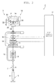
- the automatic winder (yarn winding machine) 1 includes a plurality of winder units 2 arranged next to each another and a machine control device 4.
- the machine control device 4 is adapted to control (manage) the operation of the entire automatic winder 1.
- the automatic winder 1 may further include an automatic doffing device (not illustrated).
- each winder unit 2 includes a winding unit body 3 and a unit control section 17 as the main components.
- the unit control section 17 is configured to include, for example, a Central Processing Unit (CPU), a Random Access Memory (RAM), a Read Only Memory (ROM), an Input-and-Output (I/O) port, and a communication port.
- the ROM stores a program for controlling each component of the winder unit 2.
- Each section (details will be described later) of the winder unit 2 and the machine control device 4 are connected to the I/O port and the communication port, thus enabling communication of control information and the like.
- the unit control section 17 thus can control an operation of each of the sections of the winder unit 2.
- the winding unit body 3 includes a yarn supplying section 5, a yarn unwinding assisting device 7, a tension applying device 9, a yarn monitoring device 11, a yarn joining device 13, and a winding section 15 on a yarn travelling path between a yarn supplying bobbin 6 and a contact roller 22.
- the yarn supplying section 5 is provided at a lower part of the winder unit 2.
- the yarn supplying section 5 is configured to hold the yarn supplying bobbin 6 fed by a bobbin feeding system (not illustrated) at a predetermined position.
- the yarn unwinding assisting device 7 assists unwinding of the yarn Y from the yarn supplying bobbin 6 by lowering a regulating member 8 covering a core tube of the yarn supplying bobbin 6 in conjunction with the unwinding of the yarn Y from the yarn supplying bobbin 6.
- the regulating member 8 makes contact with a balloon of the yarn Y formed at an upper part of the yarn supplying bobbin 6 by rotation and a centrifugal force of the yarn Y unwound from the yarn supplying bobbin 6 to control the balloon of the yarn Y to an appropriate size, thus assisting the unwinding of the yarn Y.
- a sensor (not illustrated) for detecting a chase portion of the yarn supplying bobbin 6 is provided in proximity to the regulating member 8. When this sensor detects lowering of the chase portion, the yarn unwinding assisting device 7 lowers the regulating member 8 by an air cylinder (not illustrated), for example, following the lowering of the chase portion.
- the tension applying device 9 applies a predetermined tension on the travelling yarn Y.
- the tension applying device 9 may be, for example, a gate type tension applying device in which movable comb teeth are arranged with respect to fixed comb teeth. Since the yarn Y bends and passes through between the engaged comb teeth, resistance is applied on the travelling yarn Y and thereby allowing an appropriate tension to be applied on the yarn Y.
- a disc type tension applying device for example, may be employed as the tension applying device 9.
- the yarn monitoring device 11 includes a sensor (not illustrated) adapted to detect an abnormal portion (yarn defect) of the yarn Y.
- a cutter 12 which is adapted to immediately cut the yarn Y when the yarn monitoring device 11 detects the yarn defect, is provided in proximity to the yarn monitoring device 11.
- the yarn joining device 13 joins a lower yarn from the yarn supplying bobbin 6 and an upper yarn from a winding bobbin 14 at the time of yarn cutting performed after the yarn monitoring device 11 detects a yarn defect, yarn breakage during unwinding of the yarn Y from the yarn supplying bobbin 6, and the like.
- the yarn joining device adapted to join the upper yarn and the lower yarn may be a mechanical knotter, a splicer using fluid such as compressed air, or the like.
- a lower yarn catching member 16 adapted to catch a lower yarn and to guide the lower yarn to the yarn joining device 13 is arranged below the yarn joining device 13.
- An upper yarn catching member 18 adapted to catch an upper yarn and to guide the upper yarn to the yarn joining device 13 is arranged above the yarn joining device 13.
- the winding section 15 includes a cradle 20 adapted to support the winding bobbin 14 for winding the yarn Y, and the contact roller 22 that rotates when brought into contact with a peripheral surface of the winding bobbin 14.
- the winding section 15 includes a rotary drive source (not illustrated) adapted to rotatably drive the winding bobbin 14 supported by the cradle 20. By driving and rotating the winding bobbin 14, the yarn Y can be wound around the outer periphery of the winding bobbin 14.
- the winding bobbin 14 around which the yarn Y is wound is referred to as a package P.
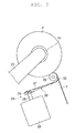
- the winder unit 2 includes an arm type traverse device 24 in proximity to the cradle 20, the traverse device 24 being adapted to traverse the yarn Y to be wound around the winding bobbin 14. As illustrated in FIG. 3 , the traverse device 24 includes a traverse drive motor (driving section) 26 and a traverse arm 30.
- the traverse drive motor 26 is a drive source adapted to swing the traverse arm 30 and is configured by a servo motor and the like.
- the traverse drive motor 26 has a swing-drive shaft 28 as an output shaft.
- the swing-drive shaft 28 is connected to a base-end portion of the traverse arm 30 in a longitudinal direction of the traverse arm 30.
- the traverse arm 30 is fixed to the swing-drive shaft 28 in a relatively non-rotatable manner. As illustrated in FIG. 3 , in a state where the traverse arm 30 is fixed to the swing-drive shaft 28, the longitudinal direction of the traverse arm 30 and the swing-drive shaft 28 are substantially perpendicular to each other.
- a traverse guide 32 is provided at a tip-end portion of the traverse arm 30 (end portion opposite to the base-end portion in the longitudinal direction).
- the traverse guide 32 is formed into a shape by which the yarn Y to be wound around the winding bobbin 14 can be guided (shape by which the yarn Y can be arranged inside or shape by which the traverse guide 32 can hook the yarn Y).
- the traverse guide 32 reciprocates with respect to a direction of a winding width of the package P (left-right direction in FIG. 2 ).
- the yarn Y is wound around the winding bobbin 14 while being traversed, thereby forming a predetermined-shaped package P.
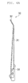
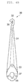
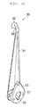
- the traverse arm 30 includes an arm body (body section) 31 and a mounting member 33.
- the arm body 31 is formed into a tapered shape.
- a side where the swing-drive shaft 28 is mounted and a side opposite thereof (side where the traverse guide 32 is formed) are respectively referred to as a "base-end (other end)" and a "tip-end (one end)".
- the arm body 31 is made of a processed plate member.
- the arm body 31 is made of a pressed aluminum plate or a pressed aluminum alloy plate.
- the material for forming the arm body 31 may be magnesium, magnesium alloy, titanium, titanium alloy, resin, or the like.
- the traverse guide 32 is provided at a tip-end portion of the arm body 31.
- the traverse guide 32 and the arm body 31 are integrally molded.
- the traverse guide 32 is formed with the arm body 31 by processing an aluminum plate or an aluminum alloy plate by a press machine.
- the traverse guide 32 is formed into a shape by which the yarn Y can be guided by the traverse guide 32.
- the traverse guide 32 is formed into a hook shape.
- a yarn guiding section 35 adapted to guide the yarn Y (to hook the yarn Y) is formed in the traverse guide 32.
- the yarn guiding section 35 is a cutout groove formed in the traverse guide 32.
- the yarn guiding section 35 extends along the longitudinal direction of the arm body 31 and is opened on a base-end side (direction of the base-end portion). The yarn Y to be traversed by the traverse device 24 slides and travels while making contact with the yarn guiding section 35.
- the mounting member 33 is mounted to the base-end portion of the arm body 31.
- the mounting member 33 is mounted to the swing-drive shaft 28.
- the arm body 31 is fixed to the swing-drive shaft 28 via the mounting member 33.
- the arm body 31 has a center of the swing located at the base-end portion.
- the mounting member 33 is a member different from the arm body 31.
- the mounting member 33 is made of aluminum, for example, and is formed by using a cutting machine, and the like.
- the mounting member 33 is provided with a mounting hole 37 for mounting the swing-drive shaft 28.
- a key groove 39 for preventing the traverse arm 30 from relatively rotating with respect to the swing-drive shaft 28 is formed in the mounting hole 37.
- the arm body 31 and the mounting member 33 are, for example, fixed by screws.
- the arm body 31 is provided with a plurality of (three herein) through holes 41, 42, 43, and the screws are screwed into the mounting member 33 via the through holes 41, 42, 43.
- the mounting member 33 is thereby mounted to the arm body 31.
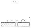
- a surface layer 44 is formed on a surface 31a of the arm body 31 having the above-described configuration.
- the surface layer 44 is formed over the entire surface 31a of the arm body 31 including the yarn guiding section 35.
- the surface layer 44 is formed by surface treatment.
- the surface treatment is treatment performed on the surface 31a of the arm body 31 to enhance the abrasion resistance and the like of the surface 31a of the arm body 31.
- the surface treatment is, for example, treatment for forming a film on the surface 31a of the arm body 31, or treatment for improving the surface 31a of the arm body 31.
- the surface layer 44 includes a first layer 45 and a second layer 46.
- the first layer 45 is directly formed on the surface 31a of the arm body 31, and the second layer 46 is formed on the first layer 45.
- the first layer 45 is, for example, chromium-based plating.
- the first layer 45 may be a single layer or may be a multi-layer.
- the component of the material of the first layer 45 may contain a gradient composition.
- the second layer 46 is, for example, a film of DLC (Diamond Like Carbon), and is formed by plasma CVD.
- the arm body 31 is made black by the second layer 46 of the DLC.
- the second layer 46 has a hardness (Vicker's hardness) higher than that of the arm body 31.
- the arm body 31 is made of aluminum or aluminum alloy, and thus the hardness of the second layer 46 is higher than the hardness of aluminum or aluminum alloy (e.g., 50 Hv to 150 Hv).
- the hardness of the second layer 46 made of DLC is, for example, 1300 Hv or more and 1500 Hv or less.
- the thickness of the second layer 46 may be appropriately set, and is, for example, 5 ⁇ m or more and 10 ⁇ m or less.
- the traverse arm 30 of the present embodiment has the surface layer 44 formed on the surface 31a of the arm body 31 including the yarn guiding section 35 by the surface treatment.
- the second layer 46 of the surface layer 44 has a hardness higher than that of the arm body 31.
- the second layer 46 of the surface layer 44 is the film of the DLC.
- the arm body 31 is made of aluminum or aluminum alloy. Therefore, the speed of swinging of the traverse arm 30 can be increased.
- the surface layer 44 is formed over the entire surface 31a of the arm body 31.
- a masking operation and the like are required, and hence the process becomes more complex.
- the surface layer 44 is formed over the entire surface 31a of the arm body 31, the masking operation and the like are not required, and thus the manufacturing can be simplified.
- the surface layer 44 functions as a rust prevention (anti-corrosion layer), and hence rust prevention (anti-corrosion) treatment is not required to be separately performed on the traverse arm 30.
- the yarn guiding section 35 is a cutout groove formed in the traverse guide 32. Therefore, the gap, the step, or the like to which the yarn Y gets caught is not formed.
- the surface layer 44 includes the first layer 45.
- the first layer 45 made of chromium-based plating has satisfactory adhesiveness with the surface 31a of the arm body 31 made of aluminum or aluminum alloy
- the second layer 46 made of DLC has satisfactory adhesiveness with the first layer 45. Therefore, stripping of the second layer 46 (the surface layer 44) can be prevented by providing the first layer 45.
- the present invention is not limited to the above-described embodiment.
- the film of DLC has been described by way of example as the second layer 46 of the surface layer 44.
- the second layer 46 of the surface layer 44 merely needs to have a hardness higher than that of the arm body 31, and may be made of, for example, ceramic, titanium nitride, hard chromium, or the like.
- the second layer 46 may be formed to contain a plurality of materials of the DLC, the ceramic, the titanium nitride, and the hard chromium.
- the surface layer can be formed on the surface 31a of the arm body 31 by a plasma powder spraying method, an explosion spraying method, or the like.
- the hardness of the ceramic is, for example, 800 Hv or more and 850 Hv or less.
- the thickness of the surface layer made of ceramic is, for example, 30 ⁇ m or more and 200 ⁇ m or less.
- the surface layer can be formed on the surface 31a of the arm body 31 by a PVD ion plating method.
- the hardness of the titanium nitride is, for example, 2200 Hv or more and 2500 Hv or less.
- the thickness of the surface layer made of titanium nitride is, for example, 2 ⁇ m or more and 4 ⁇ m or less.
- the surface layer can be formed on the surface 31a of the arm body 31 by a plating bath.
- the hardness of the hard chromium is, for example, 800 Hv or more and 1000 Hv or less.
- the surface layer 44 includes the first layer 45 and the second layer 46
- the first layer 45 may not be provided.
- the second layer 46 may be directly formed on the surface 31a of the arm body 31. Since the first layer 45 is not provided between the surface 31a of the arm body 31 and the second layer 46, the weight of the traverse arm 30 becomes lighter. Furthermore, since the process of forming the first layer 45 is not required, the traverse arm 30 can be more easily manufactured.
- the surface layer 44 includes the first layer 45 and the second layer 46 has been described by way of example, but the surface layer 44 may include other layers.
- the mounting member 33 is formed as a member different from the arm body 31, but may be integrally molded.
Landscapes
- Winding Filamentary Materials (AREA)
- Guides For Winding Or Rewinding, Or Guides For Filamentary Materials (AREA)
Applications Claiming Priority (1)
| Application Number | Priority Date | Filing Date | Title |
|---|---|---|---|
| JP2014161528A JP2016037354A (ja) | 2014-08-07 | 2014-08-07 | トラバースアーム及び糸巻取機 |
Publications (1)
| Publication Number | Publication Date |
|---|---|
| EP2982631A1 true EP2982631A1 (fr) | 2016-02-10 |
Family
ID=53776357
Family Applications (1)
| Application Number | Title | Priority Date | Filing Date |
|---|---|---|---|
| EP15178002.0A Withdrawn EP2982631A1 (fr) | 2014-08-07 | 2015-07-23 | Bras de va-et-vient et machine de bobinage de fil |
Country Status (3)
| Country | Link |
|---|---|
| EP (1) | EP2982631A1 (fr) |
| JP (1) | JP2016037354A (fr) |
| CN (1) | CN105366435A (fr) |
Citations (5)
| Publication number | Priority date | Publication date | Assignee | Title |
|---|---|---|---|---|
| US6505791B1 (en) * | 1998-06-12 | 2003-01-14 | Maschinenfabrik Rieter Ag | Thread traversing device |
| WO2007007004A2 (fr) * | 2005-07-11 | 2007-01-18 | Ritm | Dispositif de va-et-vient a bras oscillant |
| EP2537788A1 (fr) * | 2011-06-25 | 2012-12-26 | Oerlikon Textile GmbH & Co. KG | Elément de guide-fil pour un guide-fil à doigt |
| EP2570377A1 (fr) * | 2011-09-15 | 2013-03-20 | Murata Machinery, Ltd. | Guide-fil va-et-vient, unité d'enroulement et machine d'enroulement |
| JP2014069931A (ja) | 2012-09-28 | 2014-04-21 | Murata Mach Ltd | トラバースアーム、及びこれを備えた糸巻取機 |
Family Cites Families (1)
| Publication number | Priority date | Publication date | Assignee | Title |
|---|---|---|---|---|
| DE102011105553A1 (de) * | 2011-06-25 | 2012-12-27 | Oerlikon Textile Gmbh & Co. Kg | Fingerfadenführer |
-
2014
- 2014-08-07 JP JP2014161528A patent/JP2016037354A/ja active Pending
-
2015
- 2015-07-17 CN CN201510424111.XA patent/CN105366435A/zh active Pending
- 2015-07-23 EP EP15178002.0A patent/EP2982631A1/fr not_active Withdrawn
Patent Citations (5)
| Publication number | Priority date | Publication date | Assignee | Title |
|---|---|---|---|---|
| US6505791B1 (en) * | 1998-06-12 | 2003-01-14 | Maschinenfabrik Rieter Ag | Thread traversing device |
| WO2007007004A2 (fr) * | 2005-07-11 | 2007-01-18 | Ritm | Dispositif de va-et-vient a bras oscillant |
| EP2537788A1 (fr) * | 2011-06-25 | 2012-12-26 | Oerlikon Textile GmbH & Co. KG | Elément de guide-fil pour un guide-fil à doigt |
| EP2570377A1 (fr) * | 2011-09-15 | 2013-03-20 | Murata Machinery, Ltd. | Guide-fil va-et-vient, unité d'enroulement et machine d'enroulement |
| JP2014069931A (ja) | 2012-09-28 | 2014-04-21 | Murata Mach Ltd | トラバースアーム、及びこれを備えた糸巻取機 |
Also Published As
| Publication number | Publication date |
|---|---|
| JP2016037354A (ja) | 2016-03-22 |
| CN105366435A (zh) | 2016-03-02 |
Similar Documents
| Publication | Publication Date | Title |
|---|---|---|
| US8202385B2 (en) | Head for application of carbon-fibre strips and application method | |
| JP5915219B2 (ja) | 糸巻取装置 | |
| ATE503049T1 (de) | Verbesserte vorrichtung zur beschickung einer textilmaschine mit einem faden oder garn sowie beschickungsverfahren | |
| EP2738129B1 (fr) | Machine de bobinage de fil et machine textile la comprenant | |
| JP2012517904A (ja) | ワイヤソー装置およびワイヤソー装置を動作させる方法 | |
| EP2712830B1 (fr) | Bras de va-et-vient et machine de renvideur de fil l'incluant | |
| JP2017014015A (ja) | 綾巻きオートワインダの作業ユニットにおいて製造された綾巻きパッケージの密度を最適化する方法および装置 | |
| EP2570377B1 (fr) | Guide-fil va-et-vient, unité d'enroulement et machine d'enroulement | |
| EP2530039B1 (fr) | Dispositif de renvidage de fil | |
| EP2738127A2 (fr) | Machine de renvideur de fil et procédé de retrait de fil | |
| EP2966022B1 (fr) | Machine de renvidage de fil et procédé de renvidage de fil | |
| JP5505621B2 (ja) | 糸巻取機及び糸巻取方法 | |
| EP2982631A1 (fr) | Bras de va-et-vient et machine de bobinage de fil | |
| JP2010137944A (ja) | トラバースアーム及びこのトラバースアームを備える糸巻取機 | |
| EP3453662B1 (fr) | Machine d'enroulement de fil | |
| JP2013063808A (ja) | クレードル、巻取ユニット、及び糸巻取機 | |
| EP3042872A1 (fr) | Machine de bobinage de fil, bobine et procédé de fabrication d'une bobine | |
| EP2738128B1 (fr) | Machine de renvideur de fil | |
| CN105270915A (zh) | 纱线卷绕机 | |
| JP2014094786A (ja) | 綾振装置およびこれを備えた巻取装置 | |
| JP2009214984A (ja) | パッケージの製造方法、糸巻取機及びパッケージ | |
| EP3165488A1 (fr) | Guide transversal, machine de bobinage de fil et procédé de production de guide transversal | |
| WO2019155807A1 (fr) | Dispositif d'enroulage de fil et procédé d'enroulage de fil | |
| CN111132918A (zh) | 纱线卷取机 | |
| JP2018090419A (ja) | 糸接続手段 |
Legal Events
| Date | Code | Title | Description |
|---|---|---|---|
| PUAI | Public reference made under article 153(3) epc to a published international application that has entered the european phase |
Free format text: ORIGINAL CODE: 0009012 |
|
| AK | Designated contracting states |
Kind code of ref document: A1 Designated state(s): AL AT BE BG CH CY CZ DE DK EE ES FI FR GB GR HR HU IE IS IT LI LT LU LV MC MK MT NL NO PL PT RO RS SE SI SK SM TR |
|
| AX | Request for extension of the european patent |
Extension state: BA ME |
|
| STAA | Information on the status of an ep patent application or granted ep patent |
Free format text: STATUS: THE APPLICATION HAS BEEN WITHDRAWN |
|
| 18W | Application withdrawn |
Effective date: 20160711 |