EP2982873A1 - Adaptateur d'entraînement destiné à entraîner une fixation hélicoïdale dans un substrat - Google Patents
Adaptateur d'entraînement destiné à entraîner une fixation hélicoïdale dans un substrat Download PDFInfo
- Publication number
- EP2982873A1 EP2982873A1 EP15170718.9A EP15170718A EP2982873A1 EP 2982873 A1 EP2982873 A1 EP 2982873A1 EP 15170718 A EP15170718 A EP 15170718A EP 2982873 A1 EP2982873 A1 EP 2982873A1
- Authority
- EP
- European Patent Office
- Prior art keywords
- fastener
- drive
- driving
- diameter
- shank
- Prior art date
- Legal status (The legal status is an assumption and is not a legal conclusion. Google has not performed a legal analysis and makes no representation as to the accuracy of the status listed.)
- Granted
Links
Images

Classifications
-
- E—FIXED CONSTRUCTIONS
- E04—BUILDING
- E04B—GENERAL BUILDING CONSTRUCTIONS; WALLS, e.g. PARTITIONS; ROOFS; FLOORS; CEILINGS; INSULATION OR OTHER PROTECTION OF BUILDINGS
- E04B1/00—Constructions in general; Structures which are not restricted either to walls, e.g. partitions, or floors or ceilings or roofs
- E04B1/38—Connections for building structures in general
- E04B1/41—Connecting devices specially adapted for embedding in concrete or masonry
- E04B1/4178—Masonry wall ties
- E04B1/4185—Masonry wall ties for cavity walls with both wall leaves made of masonry
-
- B—PERFORMING OPERATIONS; TRANSPORTING
- B25—HAND TOOLS; PORTABLE POWER-DRIVEN TOOLS; MANIPULATORS
- B25B—TOOLS OR BENCH DEVICES NOT OTHERWISE PROVIDED FOR, FOR FASTENING, CONNECTING, DISENGAGING, OR HOLDING
- B25B13/00—Spanners; Wrenches
- B25B13/02—Spanners; Wrenches with rigid jaws
- B25B13/06—Spanners; Wrenches with rigid jaws of socket type
- B25B13/065—Spanners; Wrenches with rigid jaws of socket type characterised by the cross-section of the socket
-
- B—PERFORMING OPERATIONS; TRANSPORTING
- B25—HAND TOOLS; PORTABLE POWER-DRIVEN TOOLS; MANIPULATORS
- B25B—TOOLS OR BENCH DEVICES NOT OTHERWISE PROVIDED FOR, FOR FASTENING, CONNECTING, DISENGAGING, OR HOLDING
- B25B15/00—Screwdrivers
- B25B15/001—Screwdrivers characterised by material or shape of the tool bit
- B25B15/004—Screwdrivers characterised by material or shape of the tool bit characterised by cross-section
-
- B—PERFORMING OPERATIONS; TRANSPORTING
- B25—HAND TOOLS; PORTABLE POWER-DRIVEN TOOLS; MANIPULATORS
- B25B—TOOLS OR BENCH DEVICES NOT OTHERWISE PROVIDED FOR, FOR FASTENING, CONNECTING, DISENGAGING, OR HOLDING
- B25B23/00—Details of, or accessories for, spanners, wrenches, screwdrivers
- B25B23/0007—Connections or joints between tool parts
- B25B23/0035—Connection means between socket or screwdriver bit and tool
-
- E—FIXED CONSTRUCTIONS
- E04—BUILDING
- E04B—GENERAL BUILDING CONSTRUCTIONS; WALLS, e.g. PARTITIONS; ROOFS; FLOORS; CEILINGS; INSULATION OR OTHER PROTECTION OF BUILDINGS
- E04B1/00—Constructions in general; Structures which are not restricted either to walls, e.g. partitions, or floors or ceilings or roofs
- E04B1/38—Connections for building structures in general
- E04B1/41—Connecting devices specially adapted for embedding in concrete or masonry
- E04B1/4178—Masonry wall ties
-
- E—FIXED CONSTRUCTIONS
- E04—BUILDING
- E04G—SCAFFOLDING; FORMS; SHUTTERING; BUILDING IMPLEMENTS OR AIDS, OR THEIR USE; HANDLING BUILDING MATERIALS ON THE SITE; REPAIRING, BREAKING-UP OR OTHER WORK ON EXISTING BUILDINGS
- E04G23/00—Working measures on existing buildings
- E04G23/02—Repairing, e.g. filling cracks; Restoring; Altering; Enlarging
- E04G23/0218—Increasing or restoring the load-bearing capacity of building construction elements
- E04G23/0222—Replacing or adding wall ties
-
- F—MECHANICAL ENGINEERING; LIGHTING; HEATING; WEAPONS; BLASTING
- F16—ENGINEERING ELEMENTS AND UNITS; GENERAL MEASURES FOR PRODUCING AND MAINTAINING EFFECTIVE FUNCTIONING OF MACHINES OR INSTALLATIONS; THERMAL INSULATION IN GENERAL
- F16B—DEVICES FOR FASTENING OR SECURING CONSTRUCTIONAL ELEMENTS OR MACHINE PARTS TOGETHER, e.g. NAILS, BOLTS, CIRCLIPS, CLAMPS, CLIPS OR WEDGES; JOINTS OR JOINTING
- F16B23/00—Specially shaped nuts or heads of bolts or screws for rotations by a tool
- F16B23/0061—Specially shaped nuts or heads of bolts or screws for rotations by a tool with grooves, notches or splines on the external peripheral surface designed for tools engaging in radial direction
-
- F—MECHANICAL ENGINEERING; LIGHTING; HEATING; WEAPONS; BLASTING
- F16—ENGINEERING ELEMENTS AND UNITS; GENERAL MEASURES FOR PRODUCING AND MAINTAINING EFFECTIVE FUNCTIONING OF MACHINES OR INSTALLATIONS; THERMAL INSULATION IN GENERAL
- F16B—DEVICES FOR FASTENING OR SECURING CONSTRUCTIONAL ELEMENTS OR MACHINE PARTS TOGETHER, e.g. NAILS, BOLTS, CIRCLIPS, CLAMPS, CLIPS OR WEDGES; JOINTS OR JOINTING
- F16B25/00—Screws that cut thread in the body into which they are screwed, e.g. wood screws
- F16B25/001—Screws that cut thread in the body into which they are screwed, e.g. wood screws characterised by the material of the body into which the screw is screwed
- F16B25/0031—Screws that cut thread in the body into which they are screwed, e.g. wood screws characterised by the material of the body into which the screw is screwed the screw being designed to be screwed into different materials, e.g. a layered structure or through metallic and wooden parts
-
- F—MECHANICAL ENGINEERING; LIGHTING; HEATING; WEAPONS; BLASTING
- F16—ENGINEERING ELEMENTS AND UNITS; GENERAL MEASURES FOR PRODUCING AND MAINTAINING EFFECTIVE FUNCTIONING OF MACHINES OR INSTALLATIONS; THERMAL INSULATION IN GENERAL
- F16B—DEVICES FOR FASTENING OR SECURING CONSTRUCTIONAL ELEMENTS OR MACHINE PARTS TOGETHER, e.g. NAILS, BOLTS, CIRCLIPS, CLAMPS, CLIPS OR WEDGES; JOINTS OR JOINTING
- F16B25/00—Screws that cut thread in the body into which they are screwed, e.g. wood screws
- F16B25/10—Screws performing an additional function to thread-forming, e.g. drill screws or self-piercing screws
-
- Y—GENERAL TAGGING OF NEW TECHNOLOGICAL DEVELOPMENTS; GENERAL TAGGING OF CROSS-SECTIONAL TECHNOLOGIES SPANNING OVER SEVERAL SECTIONS OF THE IPC; TECHNICAL SUBJECTS COVERED BY FORMER USPC CROSS-REFERENCE ART COLLECTIONS [XRACs] AND DIGESTS
- Y10—TECHNICAL SUBJECTS COVERED BY FORMER USPC
- Y10T—TECHNICAL SUBJECTS COVERED BY FORMER US CLASSIFICATION
- Y10T29/00—Metal working
- Y10T29/49—Method of mechanical manufacture
- Y10T29/49826—Assembling or joining
- Y10T29/49947—Assembling or joining by applying separate fastener
- Y10T29/49963—Threaded fastener
Definitions
- the present invention is directed to a drive adaptor for transmitting at least axial force from an impact-energy driving machine to a driving shank of a helical profiled fastener.
- the fastener is arranged to be driven into a plurality of layers of a structure in which the helically profiled fastener is arranged to secure the layers substantially in relation to one another.
- the technology of connecting two or more construction elements using impact-driven helically profiled fasteners that is to say helical fixings having loosely wound thread-forming blades, has been commercially practised for the past 20 years.
- the helical fasteners rely upon the peaks and troughs of a deep set helical profile to interlock within the host material to provide anchorage.
- the fasteners are used as headless and flush finish screw-nails that are simply hammered into nailable layers whereupon they cut a helical interlocking path of penetration.
- One of the more common applications is in the connection or reconnection of two or more masonry units, whereby long slender versions of the fastener are utilised to tie two layers of a cavity structure.
- Such telescopic mechanisms are, by nature, highly elaborate and such intricacy has detrimental consequence in terms of operational reliability and cost. Indeed insertion tools of this type, or of similar design and function, commonly sell for around one hundred and seventy five US dollars.
- the tooling costs equate to a hefty nine US cents per fastener.
- the tooling cost equates to a prohibitive ninety US cents per fixing.
- Such tooling expenditure is commercially flawed, in terms of cost off-set, and as such is an impediment to the saleability and wide spread exploitation of well established fasteners.
- Such telescopic driving tools rely upon an impacting confrontation with a hosting layer to force a telescoping reaction by which to recess the tie.
- Such pounding confrontation provides further cost penalty prospect in terms of damage repair to a hosting layer; for example for the repair of damage to a buildings' façade.
- a further disadvantage of telescopic driving apparatus is the length of the assembled installation arrangement in use, which in concentric combination comprises the fastener, the extended telescopic insertion tool and the powered machinery that energises the tool.
- Such lengthy assemblies are operationally cumbersome and may compromise the usability of such a system, particularly in confined spaces.
- the arrangement of an average 9 inch (230mm) long wall tie fitted in a telescopic insertion adapter that is in turn fitted to a small rotary hammer drill is over 32 inches (800mm) long and weighs between 7- 9Ib (3-4kg).
- the process of offering up and concentrically aligning the entire set up to an average 1 ⁇ 4 inch (6.35mm) pilot hole is itself cumbersome.
- the further unwieldy process of operating the rotary hammer drill in one hand and using the other outstretched hand to restrain the hefty set up axially and rotationally during the driving operation serves to compound handling difficulties and operator fatigue.
- the invention seeks to mitigate at least one of the above-mentioned problems or provide an alternative means for and method of inserting helically profiled fasteners into a structure.
- EP 0151906 (Ollis ), which teaches tools and installation methods, including means to drive and recess a helical tube into an undersized pilot bore using a punch with a long spigot.
- Examples of commercially viable impact-driven helical wall ties are disclosed in EP 0171250 (Ollis ), GB 2262560 (Knight ) and GB 2359109 (Kemp ), which individually teach different fastener types, including those manufactured from rolled wire, drawn wire and flat strip respectively, each having loosely wound thread-forming projections along substantially the whole of the length of the fastener.
- Each document teaches specific installation methods and tools, including means by which to recess these solid helical ties into a clearance bore or partial clearance bore, said clearance having a diameter that is large enough to accommodate the full helix diameter and that of a driving sleeve.
- EP 1169524 (Knight ), which teaches a fastener having major thread forming fins and minor thread-forming fins whereby the major fins can be deformed or removed at the leading end of the fastener leaving the minor interlocking fins, which extend the whole of the length of the fastener, to drive into steel.
- the invention finds significant advantage in a modified impact driven fastening system that is used to efficiently connect and secure construction layers or elements using a solid helical fastener that can be drivingly recessed without the need for unsightly clearance bores and without the need for costly and intricate adapters of the telescopic type.
- the essential elements of the inventions are defined by the independent claims and the advantageous embodiments are distinguished in the dependent claims.
- an improved impactdrivable helical fastener according to original claim 1.
- the fastener is in the form of a solid wall tie, fixing or fastener that is formed and configured with a twisted body having a common axial core and a protruding helix adjacent to a pointed leading end and an elongate lost-end driving shank of reduced diameter at a trailing end.
- the fastener incorporates two or three loosely wound thread-cutting blade-like projections extending radially from a solid core said projections being inclined upon a sweeping helical angle of less than 42° to the longitudinal axis of said core.
- the fasteners peg-like shank has means to engage a recessing and/or countersinking drive adapter and provides the keying means by which the fastener's insertion can be neatly disguised and/or can be made non-obtrusive.
- the driving adaptor can be in the form of an unyielding essentially singular element driving and recessing adapter, which has means to co-operate with an elongate driving shaft of an improved helical fastener and means to recess the fastener without need for costly and unwieldy telescopic tool mechanisms or unsightly large diameter clearance holes.
- the adapter can be made in the form of a single substantially rigid body or alternatively in the form of an assembly of parts in a fixed relationship that together make a substantially rigid body.
- the adaptor has a fixed geometry, that is, it has no axially moving parts between the impact driving machine and the fastener.
- a method of simultaneously driving and recessing a helical wall tie fixing or fastener according to original claim 31 provides a more controlled and safer approach whereby hazards associated with malfunction of multi-part tool mechanisms are alleviated and the unwieldy balance and cumbersome length of the overall insertion arrangement is reduced and is manageable.
- an impact drivable fastening assembly according to original claim 50.
- a beneficial result of the invention is a novel and cooperative fastener and tooling arrangement having means to safely and reliably drive and recess a helical tie to offer an improved systematic fastening method.
- An additional benefit of the present invention is the efficiency of the fastener and adapter combination, which delivers extremely rapid insertion rates. For example when driven with a machine that delivers about 2 ft. lbs. of impact energy (2.7 joules) rapid thread-cutting rates of penetration of between 1 ⁇ 2 an inch and 11 ⁇ 2 inches (12.7mm and 38.1 mm) per second are readily achievable in masonry layers. This permits an average 9 inch (230mm) long tie to be fully driven and recessed in between 6 and 18 seconds, a fixing rate of between 3 and 10 per minute.
- trailing reduced diameter peg-like driving shank which permits a secure keying encasement with bore-disguising fillers.
- a drive adapter for transmitting at least axial force from an impact-energy driving machine to a driving shank of a helical profiled fastener
- said drive adaptor including a substantially rigid body having a tail end that is arranged to be engaged and driven by the impact-energy driving machine and a leading end that includes a formation that is arranged for drivingly engaging the driving shank.
- the formation may comprise a substantially axial recess that is arranged to receive the drive shank, wherein the recess includes a fixed end wall that is arranged to impart impacting drive from the driving machine to the drive shank.
- the outer periphery of the leading end may include an abrasive part or cutting formation that is arranged to abrade or cut a host material when inserting the fastener into the host material.
- the recess is dimensioned to allow relative rotational movement between the drive shank and the adaptor. For example, if the impact-energy driving machine is arranged to rotate the adaptor as well as impart an axial driving force, then the fastener is able to rotate at a different speed to the adaptor. This enables tools such as hammer drills to be used to provide the axial driving force to the fastener.
- the outer periphery of the leading end may have a smaller maximum cross sectional dimension than the maximum cross sectional dimension of the fastener.
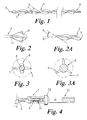
- a typical impact-driven fastener 1 of the present invention has a twisted wire body incorporating a protruding swept angle helix 3 positioned between a substantially conical or frusto-conical 11 leading point end and an elongate trailing lost-end driving shank 4 of reduced radial diameter and is shown in exemplified form at Figure 1 .
- the twisted body has a solid common axial core 2 that continues substantially the whole of the length of the fastener, said common axial core 2 having a maximum cross sectional diameter that is at least sixty percent less than a cross sectional circumscribed diameter of the fasteners helix 7. It will be appreciated that in having a twisted body and a relatively small axial core the fastener benefits from having torsional elastic properties that permit it to accommodate minor movements between affixed layers without affecting the security of connection.
- a helix 3, which tapers from the leading end of a fastener 1, is formed by two or three loosely wound thread-cutting blade-like helical projections 5 that are preferably work hardened and which extend radially from a solid common core 2 of the fastener.
- the slender thread-cutting projections are inclined upon a sweeping helical angle of less than 42° to the longitudinal axis of the core.
- the swept angle blade-like projections 5 may vary in length and are continuous around the core 2 for one full 360° rotation of pitch at least up to a length whereby they form a substantive proportion of the fasteners length, although not a full length portion.
- said swept angle blade-like projections 5 extend along at least 75% of the full length of the fastener 1.
- said swept angle blade-like projections 5 extend along less than 97% of the full length of the fastener 1.
- an integral elongate lost-end driving shank 4 which carries no swept angle thread-cutting blades.
- the elongate shank 4 has a reduced cross sectional diameter that is approximately one half or less of a cross-sectional circumscribed diameter 7 of a protruding helix 3, from which it extends coaxially such as to permit a sliding engagement into a hollow portion of a drive adapter having sufficient wall thickness to neatly recess the fastener as later described.
- Figure 2 shows the leading end of the fastener having an axial core 2 that is tapered at its leading edge. This leading point end is sharp enough to aid efficient driving and prevent wander whilst being not so sharp as to cause splitting of the material into which it is being hammered.
- the axial core 2 is locally reduced in diameter by at least 10% and not more than 90% to form a small substantially conical or frusto-conical 11 leading portion from which a plurality of helical projections gradually extend.
- the inclusive taper angle 10 at the leading portion of the fastener is greater than 40° and less than 120°.
- Figure 2A shows a portion of the fastener of Figure 1 and identifies a swept angle of the blade-like projections 5.
- the helical fastener features "sweeping" loosely wound blade-like projections 5, as opposed to conventional tightly coiled machine-screw threads, which would need to be driven with a primarily rotational driving force. That is to say the sweeping projections are essentially inclined upon an angle that is nearer to the longitudinal axis of the fastener than an angle that is perpendicular to it.
- a beneficial and cooperative sweeping angle that is between 0° and 45° to the longitudinal axis of the fastener rather than a detrimental and uncooperative angle that is between 45° and 90° to said axis.
- neither a solely axial force nor a solely rotational force is likely to drive a thread-cutting fastener having a thread angle of between 42° and 48°.
- the fastener has a full 360° rotation of pitch over an axial distance that is equal to five times the circumscribed diameter of the fasteners helix.
- the resultant sweeping helical angle 8 of the blade-like projections 5, at their outer periphery can be calculated as being a little over 32° to the longitudinal axis 9 of the fastener.
- the fasteners helical twist rate to diameter may vary from a 3.5:1 ratio up to a 8.5:1 ratio such that the helical angle 8 at the periphery of blade-like projections 5 is greater than 20° and less than 42° to the longitudinal axis of the fastener 9.
- the most preferred swept helix angle 8 is greater than 30° and less than 39° to the fasteners longitudinal axis 9.
- Figure 3 shows, in an enlarged form, a cross section of a protruding helix portion and a circumscribed diameter 7 thereof, in which slender and elongate blade-like projections 5 are tapered in cross section from a radiused cross sectional root.
- the gauge of the blade at its tip is at least 1/100 th of an inch (0.25mm) and less than 1/10 th of an inch (2.5mm).
- the example shows stubby reinforcing ribs 6 that extend radially from the core 2 and which are spaced equidistantly between the blades 5.
- the projecting ribs 6 may, at their outer periphery, have an edge thickness that is at between 1.5 times and 8.5 times an edge thickness of a blade tip and said ribs 6, which have the same pitch distance as the blades 5 but a smaller diameter, may have a sweeping helix angle of between 8° and 23° to the fastener's longitudinal axis provided that a swept helical angle of rib like projections 6 is at least 6° more shallow than a swept helical angle 8 of the thread forming blade-like projections 5.
- the length of the fastener may range from as little as 2 inches (50mm) for use in connecting slender abutting articles up to around 40 inches (1000mm) for use in connecting much thicker, or relatively widely spaced apart, components.
- the circumscribed diameter of the protruding helix portion 7 may be as small as approximately 1 ⁇ 4 inch (6.35mm), such as might be useful in instances where great flexibility of a fastener would be an asset to a particular application.
- the circumscribed diameter of the protruding helix portion 7 may measure up to about 3 ⁇ 4 inch (19mm) for uses that require greater shear resisting capacity and rigidity.
- the rigidity or flexibility of the twisted fastener is a function of its size and shape, for example the fasteners circumscribed diameter 7, the diameter of its common axial core material 2, and the provision or absence of stiffening elements such as reinforcing ribs 6 each have an effect on rigidity and torsional elasticity. Further flexural modifications are obtainable by making adjustments to the number of helical blades 5 and/or by fine-tuning the configuration of the projections in terms of dimension and pitch angle.
- Figure 3A shows in an enlarged form a cross section of a protruding helix portion that is stiffened by triangulation, and a circumscribed diameter 7 thereof, in which three equidistantly spaced blade-like projections 5 extend radially from an axial core 2.
- a helix 3 having thread-cutting blades 5 that are positioned at a relative angle of at least 120° to each other, for example those with two or three thread cutting blades 5, provides the fastener with enhanced axial grip by virtue of accommodating, within its active interlocking troughs, a larger and thus stronger portion of the host material than a helical fastener with blades that are spaced at closer angles, for example a helical fastener with four, six or eight thread-cutting blades 5.
- Fasteners having more than one protruding helix portion 3 may incorporate a different diameter and helical angle 8 upon each helix portion and this may prove useful in helically connecting layers of varying thickness, density or hardness.
- the blade-like projections are thread-cutting it is vital that the angle of helical profile is substantially uniform upon a given helix diameter.
- the motivation for the new driving adapter is the need to more safely drive and recess a solid helical fastener into and beneath a surface of a layer of a structure without reliance on complex telescoping tooling and without the need to provide an unsightly large diameter clearance bore.
- Figure 4 shows a driving adapter 21, which is made of metal or possibly a sintered compound or indeed a combination of both. It has a substantially solid shaft-like tail end 22 and a leading nose end 24 having a hollow axial slideway and is effectively of an unyielding one-piece design, that is to say the fundamental driving portions of the adapter 21 have no telescoping mechanisms or other internal workings that functionally move independently of each other.
- the hollow nose portion 24 is dimensioned to receive and cooperate with a reduced diameter shank 4 of a helical profiled fastener.
- the nose has an external diameter that is preferably smaller than a cross-sectional circumscribed diameter 7 of a helical fastener 1, as is represented by the parallel broken lines in the example shown.
- an outer periphery of the adapter's hollow nose end 24 carries a serrated or knurled portion or similar abrasive formation ( Fig 8 , 29) upon its leading section at least.
- the substantially solid shaft-like tail end 22 of the adapter 21 has means to engage an impact-energy-delivering driving machine.
- this end of the driving adapter may be fluted such as to permit connection into an SDS type chuck of a rotary hammer drilling machine.
- it may be formed to engage any suitable energising source.
- the driving adapter 21 may have a shoulder portion 23 located between each end of the adapter. Ideally the shoulder 23 may carry a compliant washer or buffer.
- the fastening method which connects a plurality of layers of a structure and secures them substantially in relation to one another, utilises a helically profiled fastener 1 that is dimensioned to fit into and cooperate with a driving and recessing adapter 21 that has no telescopic driving mechanisms or internal workings.
- the fastener 1 is impact-driven directly into softer materials such as aerated concrete 41 and softwood 42 by the adapter 21.
- the fasteners integral lost-end driving shank 4 slides neatly into a hollow slideway in the leading nose end 24 of a driving adapter 21, the tail end 22 of the adapter being fitted to an impact energy-delivering driving machine.
- the elongate driving shank 4 is of sufficient dimension to engage the driving adapter's nose portion 24 in a manner that confines the fastener 1 axially and aligns it longitudinally.
- the length of the hollow slideway in the leading end 24 of the adapter preferably ranges from approximately 1 ⁇ 8 of an inch (3mm) to about 21 ⁇ 2 inches (65mm) and is less than the length of the fastener's trailing shank 4.
- the fastening arrangement is aligned to a material layer or work piece at the desired entry point and entry angle.
- the fastener 1 is energised by an impact-driving machine/rotary impact driving machine, via axial engagement between the sectional end of the fastener's integral driving shank 4 and a base of a hollow bore within an adapter 21, whereby the fastener 1 is impelled by a series of imparted impacting forces into a host construction material or layer.
- the sweeping helical angle of the profile provides sufficient interface gradient to windingly deflect and rotate the impacted fastener 1, independently of the adapters' spin rate, if any, as its blade-like helical projections 5 set up a self generated spiral penetrative path to windingly cut corresponding helical seating grooves into a host material layer and sequentially on into a subsequent layer or series of layers.
- the fasteners small and substantially conical or frusto-conical leading portion helps to guide the fastener along its winding penetrative passage to prevent wandering.
- Fasteners that have no pointed end or that have a two dimensional chiselled chevron type formation with no substantially conical or frusto-conical portion tend to hinder the natural roll of the penetrating fastener and allow it to wander off of the desired path.
- the fastener in use can only rotate at the rate that it cuts a helical path in the host material, for example its helical pitch angle 8 may rotate the fastener one complete revolution for say each 2 inches (50mm) of penetration. It may take 2 seconds or so to drive the fastener the 2 inches (50mm) or 1 full rotation, a spin rate of just 30 revolutions per minute. This will be a different spin rate than that of the driving adapter, which is either energised by a hammer machine having no rotational speed or by a rotary hammer machine having a spin rate many times that of the helically penetrating fastener.
- the driving shank is dimensioned to fit into and cooperate with a driving adapter having a hollow leading end, wherein the inner diameter of the adapter's nose preferably has an internal diameter that is between 20% and 60% of a cross-sectional circumscribed diameter 7 of the fastener 1 such that provides a slight clearance on the driving shank in order that no rotational force or rotational brake is provided by the inner nose wall of the adapter 21 to the ties shank 4.
- the absence of any swept angle blade like projections upon the driving shank 4 permits a snag-free interface during driving.
- the leading nose 24 of the adapter which has sufficient wall thickness and abrasive periphery to form a countersink into these softer construction layers, follows a fastener's helix 3 beneath a near surface of a host material whereby the fastener 1 including its trailing lost end driving shank 4 is simultaneously recessed or countersunk to an appropriate depth.
- the adapter's hollow nose portion 24 has a wall thickness that is between 10% and 25% of a circumscribed cross sectional diameter 7 of the fastener 1 such as to provide a balance between its preferred small outer diameter and its robustness in use.
- a predetermined recessing or countersinking depth can be controlled by the provision of the shoulder portion 23 on a driving adaptor and its relationship to a blind end base within a hollow nose end 24.
- a depth-setting shoulder 23 will incorporate a compliant washer or buffer to avoid any impact damage to a host layer. It will be appreciated that as a shoulder 23 meets a surface of a host material the fastener's lost-end 4 is then set to a correct recessed depth and the adapter 21 can be immediately removed, as there is no need to drive an adapter against a hosting material in order to urge a telescopic recessing reaction.
- the fastener 1 of the present invention can be used to tie together a variety of similar or dissimilar construction material layers or work-pieces.
- articles of brick, block, concrete and timber will each yield to the impacting blades 5 such as to permit a loosely wound thread-cutting penetration by the fastener and its helical interlock anchorage.
- pilot bore is pre-formed into the host materials to facilitate and ease driving penetration.
- diameter of a pilot bore is greater than that of a fastener's common axial core 2 and lost-end driving shank yet smaller than a circumscribed diameter 7 of an active helix 3.
- diameter of a hosting pilot bore will be between 10% smaller and 55% smaller than the fastener's largest diameter.
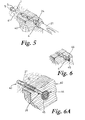
- Figure 6 illustrates a localised recess or countersink bore 44, which accommodates a fastener's reduced diameter lost end driving shank 4.
- the recess 44 can be neatly disguised by the insertion of a plug of filling material 45 that encases, and is compacted around, a peg-like lost-end shank 4, which has a sufficiently reduced radial diameter to permit the use of coarse aggregate particles where appropriate.
- the filling material preferably matches the existing finish of the structure, for example it may be a colour-formulated paste, mortar or grout that matches a face of the host material in terms of colour, texture and porosity.
- the recessed or countersunk lost-end driving shank 4 provides a good key for the retention of bore-disguising filler material 45, said keyed surface may be enhanced by the provision of shallow grooves upon a surface of the integral peg-like shank 4.
- the recessed lost-end shank portion 4 may be adapted to provide means to engage add-on components or connections, for example to engage with a push-on crown or a female connecting piece for engaging elongate members in axial alignment with the fastener or substantially perpendicular thereto.
- Figure 6A is representative of a common alternative fixing arrangement, whereby even in the softer materials, such as softwoods 42 and aerated concretes 41, more laborious operations include pre-drilling a clearance bore 43, pre-forming a countersink 44, inserting a wall plug 27, inserting and rotationally driving a screw 28 and making good a large diameter countersink 44 with a shallow dish of filler material 45, all of which fails to provide fixing reliability, deep secure keying or an inconspicuous finish.
- more laborious operations include pre-drilling a clearance bore 43, pre-forming a countersink 44, inserting a wall plug 27, inserting and rotationally driving a screw 28 and making good a large diameter countersink 44 with a shallow dish of filler material 45, all of which fails to provide fixing reliability, deep secure keying or an inconspicuous finish.
- Figures 7A and 7B are provided to illustrate functional improvements offered by the fastener 1 and the fastening system of the present invention over conventional helical fastening arrangements, notwithstanding the cost and reliability issues associated with complex insertion tooling that cannot be illustratively represented.
- the examples show a typical application for a helical wire fastener, which has been produced through slotted shaping rollers and a twisting arrangement, whereby it is used to connect two wall layers of a cavity wall construction that are of sufficient hardness to require a fine pre-formed pilot bore 53.
- the fastener is impact-driven by an insertion tool that, in this example, is energised by the rotary hammer action of a drilling machine 25 and the fastener is driven into a pilot hole 53 whereupon it windingly penetrates through the first wall 52 and into the second wall 51 such that helical projections cut into and grippingly interlock with both connected layers.
- Figure 7A illustrates the use of a conventional helical fastener, for example one that has no reduced diameter driving shank portion.
- the full diameter profile at one end of a helix is inserted into a tubular end of a large diameter telescopic driving tool 26.
- the fastener is driven until the telescopic tool 26 collides with the first wall layer 52 whereupon hammering continues until a pin telescopically protrudes from the tool to drive the fastener from the tube and recess it beneath the face of the first wall layer 52.
- the operator has to take the weight of the rotary hammer drill 25 in one hand and has to use the other hand on his outstretched arm to support the weighty telescopic tool 26 and to restrain it from against spinning uncontrollably during driving. He also has to guide this cumbersomely long and unbalanced arrangement such that the lead end of a fastener is driven concentrically into a fine pilot bore 53 that may be only a quarter of an inch (6.4mm) in diameter, or less. It will be appreciated that with only one hand on a drill 25 the operator is at risk of wrist or shoulder damage if the drill should 'snatch' due to tooling malfunction.
- Figure 7B illustrates an example of the modified fastener, adapter and fastening system in use for the same exemplified application.
- the elongate reduced diameter driving shank at the trailing end of the fastener 1 is inserted into the adapter 21 of Figure 4 , which confines the axis of said driving shank 4 and aligns the fastener 1 to a pilot hole 53 and permits a controlled and balanced driving operation within much closer working quarters.
- the fastener's pointed leading end centres it within the pilot bore 53 as the winding helical fastener 1 is impact driven until the slender leading nose end 24 of a driving adapter 21 is itself driven beneath a surface of a masonry layer 52 such as to recess the fastener 1 without complex telescopic means and without prolonged confrontation between an adapter 21 and a wall surface 52.
- the operator is thus able to work the power drill 25 safely with both hands.
- Figure 8 shows the nose 24 of an insertion adapter 21 having means to ream out and locally widen a pilot bore 53 in a near-most construction layer 52 to simultaneously provide a countersink recess 44 for the fastener 1 as its lost end driving shank 4 is driven below the surface of the hosting layer.
- This reaming and countersink forming effect is preferably achieved by the incorporation of a serrated, knurled or similar abrasive formations 29 upon an outer periphery of a leading portion at least of the adapters' nose end 24. It will be appreciated that the adapters' nose end 24 may fit neatly into a clearance afforded by larger pilot bores permitting recessing of the fastener 1 without a localised countersink formation.
- the invention can be arranged as follows:
- the impact-drivable fastener includes a twisted body having: a substantially solid common axial core; a protruding helix extending from a pointed leading end; and a trailing elongate lost-end driving shank of reduced radial diameter; wherein the protruding helix includes two or three loosely wound thread-cutting blade-like projections extending radially from the core, said projections being inclined on a sweeping helical angle of less than 42° to the longitudinal axis of said core.
- the swept angle blade-like projections are continuous around the core for at least one full 360° rotation of pitch.
- the swept angle blade-like projections of the helix can form a substantive proportion of the fastener's length, although not a full length portion.
- the swept angle blade-like projections can extend along less than 97% of the full length of the fastener.
- the swept angle blade-like projections can extend along at least 75% of the full length of the fastener.
- the elongate lost-end driving shank may carry no swept angle thread-cutting blades.
- the elongate lost-end driving shank can have a reduced cross sectional diameter that is approximately one half or less of the cross-sectional circumscribed diameter of the protruding helix.
- the elongate reduced diameter lost-end driving shank can extend coaxially with respect to the protruding helix.
- the lost-end driving shank can incorporate a keyed surface.
- the lost-end driving shank can incorporate shallow grooves on its surface.
- the lost-end driving shank can be adapted to engage add-on components or connections.
- a maximum cross sectional diameter of the common axial core is preferably at least sixty percent less than a cross sectional circumscribed diameter of the helix.
- the common axial core can be locally reduced in diameter by at least 10% to form a small substantially conical or frusto-conical leading point portion from which a plurality of helical projections gradually extend.
- the leading portion of the fastener can have an inclusive taper angle that is greater than 40°.
- the leading portion of the fastener can have an inclusive taper angle that is less than 120°.
- the blade-like projections can be inclined upon a sweeping helical angle of more than 20° to the longitudinal axis of the core.
- the angle of the helical profile is substantially uniform upon a given diameter.
- the blade-like projections can be substantially slender and elongate in cross section.
- the blade-like projections can be tapered in cross-section.
- the blade-like projections can have a radiused cross sectional root.
- the cross-sectional circumscribed diameter of the protruding helix can be approximately 1 ⁇ 4 inch (6.35mm) or more.
- the cross-sectional circumscribed diameter of the protruding helix is prefably approximately 3 ⁇ 4 inch (19mm) or less.
- the gauge of each blade-like projection at its tip is preferably at least 1/100 th of an inch (0.25mm) and less than 1/10 th of an inch (2.5mm).
- Preferably fastener includes stubby reinforcing ribs which extend radially from the axial core and are spaced equidistantly between the helical blade-like projections.
- the stubby reinforcing ribs can have at their outer periphery an edge thickness that is at between 1.5 times and 8.5 times an edge thickness of a blade tip.
- the stubby reinforcing ribs can be inclined upon a sweeping helical angle of between 8° and 23° to the longitudinal axis of the core.
- a swept helical angle of the stubby rib like projections is preferably at least 6° more shallow than the swept helical angle of the thread forming blade-like projections
- the driving shank is preferably dimensioned to fit into and cooperate with a driving adapter having a hollow leading end, said leading end of the driving adapter having an external diameter that is less than a cross-sectional circumscribed diameter of the fastener.
- the driving shank is preferably dimensioned to fit into and cooperate with a driving adapter having a hollow leading end, wherein the inner diameter of the adapter's nose has an internal diameter that is between 20% and 60% of a cross-sectional circumscribed diameter of the fastener.
- the fastener can be, in use, recessed or countersunk.
- a method for connecting a plurality of layers of a structure using a helically profiled fastener having a twisted body having a common axial core, a protruding helix and an integral elongate lost-end driving shank of reduced radial diameter including: sliding the driving shank into a hollow slideway in a leading nose of an unyielding driving adapter, which is fitted to an impact-energy driving machine; aligning the fastener arrangement to a hosting material layer; energising the fastener with the impact-driving machine via the adapter; whereupon the fastener is impelled by a series of impacting forces to windingly cut helical grooves into the host material layer and onwards into a subsequent layer until the adapter's leading hollow nose penetrates the near surface of the host material layer whereby the fastener and its lost-end driving shank is recessed or countersunk.
- the method can include a preparatory step of pre-drilling a pilot bore into a host material.
- the pilot bore can have a greater diameter than that of the maximum common axial core and has a smaller diameter than the circumscribed diameter of the protruding helix.
- the pilot bore can have a greater diameter than that of the integral driving shank and has a smaller diameter than the circumscribed diameter of the protruding helix.
- the adapter can include an abrasive formation upon its nose portion to ream out or locally widen the pilot bore into which the nose is simultaneously driven in order to countersink the fastener.
- the adapter can include an abrasive formation upon the rigid wall of its nose portion and simultaneously forms a countersink in the construction material as the fastener is driven therein.
- the thread-cutting rates of penetration are preferably 1 ⁇ 2 an inch (12.7mm) or more per second.
- the method can include a further step of disguising a fastener entry bore by inserting therein filling material to encase and key to the recessed or countersunk lost-end driving shank.
- the lost end driving shank can include means to engage add-on components.
- the method can include providing a shoulder portion on the driving adaptor that sets a predetermined recessing or countersinking depth via its relationship to a blind end base within the hollow nose end.
- the method can include providing a compliant washer or buffer upon the adapter shoulder portion.
- the length of the hollow slideway can be less than the length of the driving shank.
- the hollow nose end can have an external diameter that is smaller than the cross-sectional circumscribed diameter of the helical fastener.
- the hollow slideway within the nose end can have an internal diameter that is between 20% and 60% of a cross-sectional circumscribed diameter of the fastener.
- the hollow nose portion can have a wall thickness that is between 10% and 25% of a cross-sectional circumscribed diameter of the fastener.
- the helically profiled fastener can be a fastener according to any configuration described herein.
- an unyielding drive adapter for transmitting axial force from an impact-energy driving machine to a driving shank of a helical profiled fastener, said drive adaptor having: a driven shaft end having means to engage the impact-energy driving machine; and a leading nose end having a hollow axial slideway that is dimensioned to receive and cooperate with the reduced diameter shank of the helical profiled fastener; wherein the outer periphery of the leading nose end includes an abrasive part or cutting formation that is arranged to abrade or cut a host material.
- the adapter can incorporate a shoulder portion between its driven shank end and its driving hollow nose end.
- the shoulder can carry a compliant washer or buffer.
- an impact drivable fastening assembly comprising: a helically profiled fastener according to any one of claims 1 to 30; and an unyielding drive adapter according to any one of claims 47 to 49; wherein the adapters hollow nose end includes means to engage a reduced diameter driving shank of the helically profiled fastener and is arranged to permit the engaged helical fastener to rotate independently of the adapter.
- the hollow nose end can have an external diameter that is smaller than a cross-sectional circumscribed diameter of a helical fastener.
- the hollow nose end can have an internal diameter that is between 20% and 60% of a cross-sectional circumscribed diameter of the fastener.
- the hollow nose portion can have a wall thickness that is between 10% and 25% of a cross-sectional circumscribed diameter of the fastener.
Landscapes
- Engineering & Computer Science (AREA)
- Architecture (AREA)
- Mechanical Engineering (AREA)
- General Engineering & Computer Science (AREA)
- Civil Engineering (AREA)
- Structural Engineering (AREA)
- Electromagnetism (AREA)
- Physics & Mathematics (AREA)
- Electrochemistry (AREA)
- Chemical Kinetics & Catalysis (AREA)
- Chemical & Material Sciences (AREA)
- Processing Of Stones Or Stones Resemblance Materials (AREA)
- Dowels (AREA)
- Joining Of Building Structures In Genera (AREA)
Applications Claiming Priority (2)
| Application Number | Priority Date | Filing Date | Title |
|---|---|---|---|
| GBGB0612745.0A GB0612745D0 (en) | 2006-06-27 | 2006-06-27 | Impact driven fastener and fastening system |
| EP07700349.9A EP2032863B1 (fr) | 2006-06-27 | 2007-01-10 | Élément de fixation et système de fixation |
Related Parent Applications (1)
| Application Number | Title | Priority Date | Filing Date |
|---|---|---|---|
| EP07700349.9A Division EP2032863B1 (fr) | 2006-06-27 | 2007-01-10 | Élément de fixation et système de fixation |
Publications (2)
| Publication Number | Publication Date |
|---|---|
| EP2982873A1 true EP2982873A1 (fr) | 2016-02-10 |
| EP2982873B1 EP2982873B1 (fr) | 2017-03-01 |
Family
ID=36888162
Family Applications (2)
| Application Number | Title | Priority Date | Filing Date |
|---|---|---|---|
| EP07700349.9A Active EP2032863B1 (fr) | 2006-06-27 | 2007-01-10 | Élément de fixation et système de fixation |
| EP15170718.9A Active EP2982873B1 (fr) | 2006-06-27 | 2007-01-10 | Adaptateur d'entraînement destiné à entraîner une fixation hélicoïdale dans un substrat |
Family Applications Before (1)
| Application Number | Title | Priority Date | Filing Date |
|---|---|---|---|
| EP07700349.9A Active EP2032863B1 (fr) | 2006-06-27 | 2007-01-10 | Élément de fixation et système de fixation |
Country Status (7)
| Country | Link |
|---|---|
| US (1) | US8192125B2 (fr) |
| EP (2) | EP2032863B1 (fr) |
| CN (1) | CN101479487B (fr) |
| AU (1) | AU2007264783B2 (fr) |
| GB (2) | GB0612745D0 (fr) |
| PL (1) | PL2032863T3 (fr) |
| WO (1) | WO2008001031A1 (fr) |
Families Citing this family (11)
| Publication number | Priority date | Publication date | Assignee | Title |
|---|---|---|---|---|
| GB0019786D0 (en) * | 2000-08-12 | 2000-09-27 | Ollis William H | Method of manufacturing connecting devices |
| GB2501462B (en) * | 2012-03-26 | 2016-12-28 | Wallfast Ltd | Structural fixing |
| US8904731B2 (en) | 2013-02-28 | 2014-12-09 | Columbia Insurance Company | Laser configured hook column anchors and anchoring systems utilizing the same |
| US9458626B2 (en) * | 2013-03-07 | 2016-10-04 | Columbia Insurance Company | Laser configured column anchors and anchoring systems utilizing the same |
| GB201518060D0 (en) * | 2015-10-13 | 2015-11-25 | Ollis William H And Ollis Jack W | Spiral head anchor |
| TWM576950U (zh) | 2017-07-25 | 2019-04-21 | 美商米沃奇電子工具公司 | 成角適配器 |
| CN109469347B (zh) * | 2018-10-30 | 2021-03-05 | 河北省建筑科学研究院有限公司 | 一种应用于装配式体外预应力的一字型端锚固装置 |
| GB201912551D0 (en) * | 2019-09-01 | 2019-10-16 | Product Licensing Company Ltd | Method & means of forming threaded ties and rods |
| CN114576251A (zh) * | 2022-03-23 | 2022-06-03 | 深圳数码模汽车技术有限公司 | 一种零件自动化排钉及折弯工艺 |
| KR200498219Y1 (ko) * | 2024-03-04 | 2024-08-05 | 김정현 | 조적벽체 보강 구조체 |
| KR102691425B1 (ko) * | 2024-03-04 | 2024-08-05 | 김정현 | 조적벽체 보강 구조체를 이용한 벽체 내진 공법 |
Citations (8)
| Publication number | Priority date | Publication date | Assignee | Title |
|---|---|---|---|---|
| EP0151906A2 (fr) | 1983-08-11 | 1985-08-21 | Hydraulic Specialty Company | Filtre pour fluide placé dans un courant secondaire |
| DE8529898U1 (de) * | 1985-10-22 | 1985-12-05 | Hebel GmbH Holding, 8080 Emmering | Befestigungsvorrichtung zur Befestigung von Konstruktionsteilen an Porenbetonteilen |
| EP0171250A2 (fr) | 1984-07-31 | 1986-02-12 | OLLIS, William John Bernard | Méthode de fabrication d'une armature de liaison pour murs et armature obtenue par cette méthode |
| GB2262560A (en) | 1991-12-19 | 1993-06-23 | Keith Knight | Wall ties |
| EP0741217A1 (fr) * | 1995-05-02 | 1996-11-06 | Helifix Limited | Système de fixation à sec |
| US5586605A (en) | 1994-02-28 | 1996-12-24 | Helifix Ltd. | Multi-wall tie apparatus |
| GB2359109A (en) | 2000-02-09 | 2001-08-15 | Cheshunt Engineering Ltd | Wall tie |
| EP1169524A1 (fr) | 1999-04-09 | 2002-01-09 | Keith Knight | Element de fixation murale |
Family Cites Families (10)
| Publication number | Priority date | Publication date | Assignee | Title |
|---|---|---|---|---|
| DE83203C (fr) | ||||
| GB2103965A (en) * | 1981-08-24 | 1983-03-02 | John Walker | Chucks having jaws with countersinking means |
| GB8400160D0 (en) | 1984-01-05 | 1984-02-08 | Ollis W J B | Helical dowel |
| DE3716808A1 (de) | 1987-05-19 | 1988-12-01 | Herbert Kern | Schraube |
| GB8714775D0 (en) * | 1987-06-24 | 1987-07-29 | Clan Contracting Ltd | Ties for building structures |
| JP2563069B2 (ja) * | 1992-06-26 | 1996-12-11 | ダブリュウ.エー.ドイッチャー プロプリタリー リミテッド | 釘 |
| US6039125A (en) * | 1994-02-28 | 2000-03-21 | Helifix Limited | Wall tie reinforcement and method |
| US6520509B1 (en) * | 1999-08-13 | 2003-02-18 | Maxtech Manufacturing Inc. | Screw guide device with drill bit/screw bit and counter sink/drill stop means |
| GB0019786D0 (en) * | 2000-08-12 | 2000-09-27 | Ollis William H | Method of manufacturing connecting devices |
| JP4501757B2 (ja) * | 2005-04-11 | 2010-07-14 | 日立工機株式会社 | インパクト工具 |
-
2006
- 2006-06-27 GB GBGB0612745.0A patent/GB0612745D0/en not_active Ceased
-
2007
- 2007-01-10 CN CN200780024063.9A patent/CN101479487B/zh active Active
- 2007-01-10 WO PCT/GB2007/000047 patent/WO2008001031A1/fr not_active Ceased
- 2007-01-10 PL PL07700349T patent/PL2032863T3/pl unknown
- 2007-01-10 EP EP07700349.9A patent/EP2032863B1/fr active Active
- 2007-01-10 US US12/306,711 patent/US8192125B2/en active Active
- 2007-01-10 AU AU2007264783A patent/AU2007264783B2/en active Active
- 2007-01-10 GB GB0711897A patent/GB2439633B/en active Active
- 2007-01-10 EP EP15170718.9A patent/EP2982873B1/fr active Active
Patent Citations (8)
| Publication number | Priority date | Publication date | Assignee | Title |
|---|---|---|---|---|
| EP0151906A2 (fr) | 1983-08-11 | 1985-08-21 | Hydraulic Specialty Company | Filtre pour fluide placé dans un courant secondaire |
| EP0171250A2 (fr) | 1984-07-31 | 1986-02-12 | OLLIS, William John Bernard | Méthode de fabrication d'une armature de liaison pour murs et armature obtenue par cette méthode |
| DE8529898U1 (de) * | 1985-10-22 | 1985-12-05 | Hebel GmbH Holding, 8080 Emmering | Befestigungsvorrichtung zur Befestigung von Konstruktionsteilen an Porenbetonteilen |
| GB2262560A (en) | 1991-12-19 | 1993-06-23 | Keith Knight | Wall ties |
| US5586605A (en) | 1994-02-28 | 1996-12-24 | Helifix Ltd. | Multi-wall tie apparatus |
| EP0741217A1 (fr) * | 1995-05-02 | 1996-11-06 | Helifix Limited | Système de fixation à sec |
| EP1169524A1 (fr) | 1999-04-09 | 2002-01-09 | Keith Knight | Element de fixation murale |
| GB2359109A (en) | 2000-02-09 | 2001-08-15 | Cheshunt Engineering Ltd | Wall tie |
Also Published As
| Publication number | Publication date |
|---|---|
| GB2439633A (en) | 2008-01-02 |
| GB2439633B (en) | 2009-09-02 |
| CN101479487B (zh) | 2011-08-17 |
| WO2008001031A1 (fr) | 2008-01-03 |
| EP2032863A1 (fr) | 2009-03-11 |
| EP2032863B1 (fr) | 2015-07-08 |
| AU2007264783A1 (en) | 2008-01-03 |
| US20090279983A1 (en) | 2009-11-12 |
| GB0612745D0 (en) | 2006-08-09 |
| EP2982873B1 (fr) | 2017-03-01 |
| PL2032863T3 (pl) | 2015-10-30 |
| CN101479487A (zh) | 2009-07-08 |
| GB0711897D0 (en) | 2007-07-25 |
| US8192125B2 (en) | 2012-06-05 |
| AU2007264783B2 (en) | 2013-01-17 |
Similar Documents
| Publication | Publication Date | Title |
|---|---|---|
| EP2032863B1 (fr) | Élément de fixation et système de fixation | |
| US7267513B2 (en) | Spade drill bit | |
| US20100247267A1 (en) | Method for anchoring a fastening element in a mineral component, and fastening element for mineral components | |
| US20080014048A1 (en) | Anchoring drill bit, system and method of anchoring | |
| US20190388976A1 (en) | Side-lock modular drill with spring-assisted bump-off | |
| WO2018067247A1 (fr) | Élément de fixation fileté à ailettes | |
| US11746819B2 (en) | Multifunction drill bit with a replaceable tip | |
| US10954982B2 (en) | Construction nailing screw | |
| US20190232391A1 (en) | Drill bit | |
| EP2507002B1 (fr) | Perceuse rotative | |
| CN103726789A (zh) | 凿岩钻头 | |
| US20040079556A1 (en) | Concrete drill | |
| EP3156667A1 (fr) | Ancrage servant à fixer un isolant sur un substrat | |
| US5746095A (en) | Method of forming rotary drilling tools | |
| EP1606073A1 (fr) | Trepan en forme de pelle | |
| JP3849793B2 (ja) | ドリル及びセルフドリルネジ | |
| US6845827B2 (en) | Rock drill head | |
| HU223127B1 (hu) | Ütve fúró szerszám kőzetekhez | |
| CN210025633U (zh) | 无绳电动工具及其钻头 | |
| EP4426954B1 (fr) | Vis, son utilisation et procédé de fixation de pièces sur une terrasse et de pose de celle-ci | |
| US20060117543A1 (en) | Method of rotary impact driving and apparatus | |
| US20230093803A1 (en) | Driver for nail anchor | |
| KR20200000750U (ko) | 셀프 드릴형 다단 직결 나사못 | |
| DK202170536A1 (en) | Screw, its use and a method for fastening wood plastic composite workpieces |
Legal Events
| Date | Code | Title | Description |
|---|---|---|---|
| PUAI | Public reference made under article 153(3) epc to a published international application that has entered the european phase |
Free format text: ORIGINAL CODE: 0009012 |
|
| AC | Divisional application: reference to earlier application |
Ref document number: 2032863 Country of ref document: EP Kind code of ref document: P |
|
| AK | Designated contracting states |
Kind code of ref document: A1 Designated state(s): AT BE BG CH CY CZ DE DK EE ES FI FR GB GR HU IE IS IT LI LT LU LV MC NL PL PT RO SE SI SK TR |
|
| 17P | Request for examination filed |
Effective date: 20160413 |
|
| RBV | Designated contracting states (corrected) |
Designated state(s): AT BE BG CH CY CZ DE DK EE ES FI FR GB GR HU IE IS IT LI LT LU LV MC NL PL PT RO SE SI SK TR |
|
| 17Q | First examination report despatched |
Effective date: 20160525 |
|
| GRAP | Despatch of communication of intention to grant a patent |
Free format text: ORIGINAL CODE: EPIDOSNIGR1 |
|
| STAA | Information on the status of an ep patent application or granted ep patent |
Free format text: STATUS: GRANT OF PATENT IS INTENDED |
|
| INTG | Intention to grant announced |
Effective date: 20161205 |
|
| GRAS | Grant fee paid |
Free format text: ORIGINAL CODE: EPIDOSNIGR3 |
|
| GRAA | (expected) grant |
Free format text: ORIGINAL CODE: 0009210 |
|
| STAA | Information on the status of an ep patent application or granted ep patent |
Free format text: STATUS: THE PATENT HAS BEEN GRANTED |
|
| AC | Divisional application: reference to earlier application |
Ref document number: 2032863 Country of ref document: EP Kind code of ref document: P |
|
| AK | Designated contracting states |
Kind code of ref document: B1 Designated state(s): AT BE BG CH CY CZ DE DK EE ES FI FR GB GR HU IE IS IT LI LT LU LV MC NL PL PT RO SE SI SK TR |
|
| REG | Reference to a national code |
Ref country code: GB Ref legal event code: FG4D |
|
| REG | Reference to a national code |
Ref country code: CH Ref legal event code: EP Ref country code: AT Ref legal event code: REF Ref document number: 871727 Country of ref document: AT Kind code of ref document: T Effective date: 20170315 |
|
| REG | Reference to a national code |
Ref country code: IE Ref legal event code: FG4D |
|
| REG | Reference to a national code |
Ref country code: DE Ref legal event code: R096 Ref document number: 602007050038 Country of ref document: DE |
|
| REG | Reference to a national code |
Ref country code: NL Ref legal event code: FP |
|
| REG | Reference to a national code |
Ref country code: LT Ref legal event code: MG4D |
|
| REG | Reference to a national code |
Ref country code: AT Ref legal event code: MK05 Ref document number: 871727 Country of ref document: AT Kind code of ref document: T Effective date: 20170301 |
|
| PG25 | Lapsed in a contracting state [announced via postgrant information from national office to epo] |
Ref country code: LT Free format text: LAPSE BECAUSE OF FAILURE TO SUBMIT A TRANSLATION OF THE DESCRIPTION OR TO PAY THE FEE WITHIN THE PRESCRIBED TIME-LIMIT Effective date: 20170301 Ref country code: GR Free format text: LAPSE BECAUSE OF FAILURE TO SUBMIT A TRANSLATION OF THE DESCRIPTION OR TO PAY THE FEE WITHIN THE PRESCRIBED TIME-LIMIT Effective date: 20170602 Ref country code: FI Free format text: LAPSE BECAUSE OF FAILURE TO SUBMIT A TRANSLATION OF THE DESCRIPTION OR TO PAY THE FEE WITHIN THE PRESCRIBED TIME-LIMIT Effective date: 20170301 |
|
| PG25 | Lapsed in a contracting state [announced via postgrant information from national office to epo] |
Ref country code: AT Free format text: LAPSE BECAUSE OF FAILURE TO SUBMIT A TRANSLATION OF THE DESCRIPTION OR TO PAY THE FEE WITHIN THE PRESCRIBED TIME-LIMIT Effective date: 20170301 Ref country code: LV Free format text: LAPSE BECAUSE OF FAILURE TO SUBMIT A TRANSLATION OF THE DESCRIPTION OR TO PAY THE FEE WITHIN THE PRESCRIBED TIME-LIMIT Effective date: 20170301 Ref country code: SE Free format text: LAPSE BECAUSE OF FAILURE TO SUBMIT A TRANSLATION OF THE DESCRIPTION OR TO PAY THE FEE WITHIN THE PRESCRIBED TIME-LIMIT Effective date: 20170301 Ref country code: ES Free format text: LAPSE BECAUSE OF FAILURE TO SUBMIT A TRANSLATION OF THE DESCRIPTION OR TO PAY THE FEE WITHIN THE PRESCRIBED TIME-LIMIT Effective date: 20170301 Ref country code: BG Free format text: LAPSE BECAUSE OF FAILURE TO SUBMIT A TRANSLATION OF THE DESCRIPTION OR TO PAY THE FEE WITHIN THE PRESCRIBED TIME-LIMIT Effective date: 20170601 |
|
| PG25 | Lapsed in a contracting state [announced via postgrant information from national office to epo] |
Ref country code: CZ Free format text: LAPSE BECAUSE OF FAILURE TO SUBMIT A TRANSLATION OF THE DESCRIPTION OR TO PAY THE FEE WITHIN THE PRESCRIBED TIME-LIMIT Effective date: 20170301 Ref country code: SK Free format text: LAPSE BECAUSE OF FAILURE TO SUBMIT A TRANSLATION OF THE DESCRIPTION OR TO PAY THE FEE WITHIN THE PRESCRIBED TIME-LIMIT Effective date: 20170301 Ref country code: RO Free format text: LAPSE BECAUSE OF FAILURE TO SUBMIT A TRANSLATION OF THE DESCRIPTION OR TO PAY THE FEE WITHIN THE PRESCRIBED TIME-LIMIT Effective date: 20170301 Ref country code: EE Free format text: LAPSE BECAUSE OF FAILURE TO SUBMIT A TRANSLATION OF THE DESCRIPTION OR TO PAY THE FEE WITHIN THE PRESCRIBED TIME-LIMIT Effective date: 20170301 |
|
| PG25 | Lapsed in a contracting state [announced via postgrant information from national office to epo] |
Ref country code: PT Free format text: LAPSE BECAUSE OF FAILURE TO SUBMIT A TRANSLATION OF THE DESCRIPTION OR TO PAY THE FEE WITHIN THE PRESCRIBED TIME-LIMIT Effective date: 20170703 Ref country code: IS Free format text: LAPSE BECAUSE OF FAILURE TO SUBMIT A TRANSLATION OF THE DESCRIPTION OR TO PAY THE FEE WITHIN THE PRESCRIBED TIME-LIMIT Effective date: 20170701 Ref country code: PL Free format text: LAPSE BECAUSE OF FAILURE TO SUBMIT A TRANSLATION OF THE DESCRIPTION OR TO PAY THE FEE WITHIN THE PRESCRIBED TIME-LIMIT Effective date: 20170301 |
|
| REG | Reference to a national code |
Ref country code: DE Ref legal event code: R097 Ref document number: 602007050038 Country of ref document: DE |
|
| PLBE | No opposition filed within time limit |
Free format text: ORIGINAL CODE: 0009261 |
|
| STAA | Information on the status of an ep patent application or granted ep patent |
Free format text: STATUS: NO OPPOSITION FILED WITHIN TIME LIMIT |
|
| PG25 | Lapsed in a contracting state [announced via postgrant information from national office to epo] |
Ref country code: DK Free format text: LAPSE BECAUSE OF FAILURE TO SUBMIT A TRANSLATION OF THE DESCRIPTION OR TO PAY THE FEE WITHIN THE PRESCRIBED TIME-LIMIT Effective date: 20170301 |
|
| 26N | No opposition filed |
Effective date: 20171204 |
|
| PG25 | Lapsed in a contracting state [announced via postgrant information from national office to epo] |
Ref country code: SI Free format text: LAPSE BECAUSE OF FAILURE TO SUBMIT A TRANSLATION OF THE DESCRIPTION OR TO PAY THE FEE WITHIN THE PRESCRIBED TIME-LIMIT Effective date: 20170301 |
|
| REG | Reference to a national code |
Ref country code: CH Ref legal event code: PL |
|
| PG25 | Lapsed in a contracting state [announced via postgrant information from national office to epo] |
Ref country code: FR Free format text: LAPSE BECAUSE OF NON-PAYMENT OF DUE FEES Effective date: 20180131 Ref country code: LU Free format text: LAPSE BECAUSE OF NON-PAYMENT OF DUE FEES Effective date: 20180110 |
|
| REG | Reference to a national code |
Ref country code: FR Ref legal event code: ST Effective date: 20180928 |
|
| PG25 | Lapsed in a contracting state [announced via postgrant information from national office to epo] |
Ref country code: CH Free format text: LAPSE BECAUSE OF NON-PAYMENT OF DUE FEES Effective date: 20180131 Ref country code: LI Free format text: LAPSE BECAUSE OF NON-PAYMENT OF DUE FEES Effective date: 20180131 |
|
| PG25 | Lapsed in a contracting state [announced via postgrant information from national office to epo] |
Ref country code: MC Free format text: LAPSE BECAUSE OF FAILURE TO SUBMIT A TRANSLATION OF THE DESCRIPTION OR TO PAY THE FEE WITHIN THE PRESCRIBED TIME-LIMIT Effective date: 20170301 |
|
| REG | Reference to a national code |
Ref country code: DE Ref legal event code: R082 Ref document number: 602007050038 Country of ref document: DE Representative=s name: HERNANDEZ, YORCK, DIPL.-ING., DE Ref country code: DE Ref legal event code: R081 Ref document number: 602007050038 Country of ref document: DE Owner name: PRODUCT LICENSING COMPANY LTD., PORTSMOUTH, GB Free format text: FORMER OWNERS: CHADWICK, DAVID, JAMES, MANCHESTER, GB; OLLIS, WILLIAM HENRY, HADDENHAM, BUCKINGHAMSHIRE, GB |
|
| REG | Reference to a national code |
Ref country code: BE Ref legal event code: PD Owner name: PRODUCT LICENSING COMPANY LIMITED; GB Free format text: DETAILS ASSIGNMENT: CHANGE OF OWNER(S), CESSION; FORMER OWNER NAME: CHADWICK, DAVID, JAMES Effective date: 20190822 |
|
| REG | Reference to a national code |
Ref country code: GB Ref legal event code: 732E Free format text: REGISTERED BETWEEN 20191003 AND 20191009 |
|
| REG | Reference to a national code |
Ref country code: NL Ref legal event code: PD Owner name: PRODUCT LICENSING COMPANY LIMITED; GB Free format text: DETAILS ASSIGNMENT: CHANGE OF OWNER(S), ASSIGNMENT; FORMER OWNER NAME: OLLIS, WILLIAM HENRY Effective date: 20191206 |
|
| PG25 | Lapsed in a contracting state [announced via postgrant information from national office to epo] |
Ref country code: TR Free format text: LAPSE BECAUSE OF FAILURE TO SUBMIT A TRANSLATION OF THE DESCRIPTION OR TO PAY THE FEE WITHIN THE PRESCRIBED TIME-LIMIT Effective date: 20170301 |
|
| PG25 | Lapsed in a contracting state [announced via postgrant information from national office to epo] |
Ref country code: HU Free format text: LAPSE BECAUSE OF FAILURE TO SUBMIT A TRANSLATION OF THE DESCRIPTION OR TO PAY THE FEE WITHIN THE PRESCRIBED TIME-LIMIT; INVALID AB INITIO Effective date: 20070110 Ref country code: CY Free format text: LAPSE BECAUSE OF FAILURE TO SUBMIT A TRANSLATION OF THE DESCRIPTION OR TO PAY THE FEE WITHIN THE PRESCRIBED TIME-LIMIT Effective date: 20170301 |
|
| PGFP | Annual fee paid to national office [announced via postgrant information from national office to epo] |
Ref country code: NL Payment date: 20260129 Year of fee payment: 20 |
|
| PGFP | Annual fee paid to national office [announced via postgrant information from national office to epo] |
Ref country code: GB Payment date: 20260202 Year of fee payment: 20 |
|
| PGFP | Annual fee paid to national office [announced via postgrant information from national office to epo] |
Ref country code: DE Payment date: 20260130 Year of fee payment: 20 Ref country code: IE Payment date: 20260202 Year of fee payment: 20 |
|
| PGFP | Annual fee paid to national office [announced via postgrant information from national office to epo] |
Ref country code: BE Payment date: 20260201 Year of fee payment: 20 Ref country code: IT Payment date: 20260130 Year of fee payment: 20 |