EP2983263B1 - Strombegrenzungs-/-flusssteuerungsvorrichtung - Google Patents
Strombegrenzungs-/-flusssteuerungsvorrichtung Download PDFInfo
- Publication number
- EP2983263B1 EP2983263B1 EP14779757.5A EP14779757A EP2983263B1 EP 2983263 B1 EP2983263 B1 EP 2983263B1 EP 14779757 A EP14779757 A EP 14779757A EP 2983263 B1 EP2983263 B1 EP 2983263B1
- Authority
- EP
- European Patent Office
- Prior art keywords
- current
- limiting
- power
- control device
- flow control
- Prior art date
- Legal status (The legal status is an assumption and is not a legal conclusion. Google has not performed a legal analysis and makes no representation as to the accuracy of the status listed.)
- Active
Links
- 239000003990 capacitor Substances 0.000 claims description 36
- 239000002887 superconductor Substances 0.000 claims description 9
- 230000007704 transition Effects 0.000 claims description 8
- 238000011084 recovery Methods 0.000 claims description 5
- 238000000034 method Methods 0.000 claims description 3
- 230000005540 biological transmission Effects 0.000 description 27
- 238000004088 simulation Methods 0.000 description 15
- 230000001939 inductive effect Effects 0.000 description 12
- 230000000694 effects Effects 0.000 description 8
- 230000008859 change Effects 0.000 description 3
- 238000010586 diagram Methods 0.000 description 3
- 238000009434 installation Methods 0.000 description 2
- 230000001052 transient effect Effects 0.000 description 2
- 238000012795 verification Methods 0.000 description 2
- 230000003247 decreasing effect Effects 0.000 description 1
- 238000011161 development Methods 0.000 description 1
- 238000002474 experimental method Methods 0.000 description 1
- 238000010304 firing Methods 0.000 description 1
- 238000003780 insertion Methods 0.000 description 1
- 230000037431 insertion Effects 0.000 description 1
- 238000012423 maintenance Methods 0.000 description 1
- 238000012986 modification Methods 0.000 description 1
- 230000004048 modification Effects 0.000 description 1
- 230000008569 process Effects 0.000 description 1
- 230000001629 suppression Effects 0.000 description 1
Images

Classifications
-
- H—ELECTRICITY
- H02—GENERATION; CONVERSION OR DISTRIBUTION OF ELECTRIC POWER
- H02H—EMERGENCY PROTECTIVE CIRCUIT ARRANGEMENTS
- H02H9/00—Emergency protective circuit arrangements for limiting excess current or voltage without disconnection
- H02H9/02—Emergency protective circuit arrangements for limiting excess current or voltage without disconnection responsive to excess current
- H02H9/023—Current limitation using superconducting elements
-
- H—ELECTRICITY
- H02—GENERATION; CONVERSION OR DISTRIBUTION OF ELECTRIC POWER
- H02H—EMERGENCY PROTECTIVE CIRCUIT ARRANGEMENTS
- H02H3/00—Emergency protective circuit arrangements for automatic disconnection directly responsive to an undesired change from normal electric working condition with or without subsequent reconnection ; integrated protection
- H02H3/08—Emergency protective circuit arrangements for automatic disconnection directly responsive to an undesired change from normal electric working condition with or without subsequent reconnection ; integrated protection responsive to excess current
-
- H—ELECTRICITY
- H02—GENERATION; CONVERSION OR DISTRIBUTION OF ELECTRIC POWER
- H02H—EMERGENCY PROTECTIVE CIRCUIT ARRANGEMENTS
- H02H9/00—Emergency protective circuit arrangements for limiting excess current or voltage without disconnection
- H02H9/02—Emergency protective circuit arrangements for limiting excess current or voltage without disconnection responsive to excess current
- H02H9/021—Current limitation using saturable reactors
-
- Y—GENERAL TAGGING OF NEW TECHNOLOGICAL DEVELOPMENTS; GENERAL TAGGING OF CROSS-SECTIONAL TECHNOLOGIES SPANNING OVER SEVERAL SECTIONS OF THE IPC; TECHNICAL SUBJECTS COVERED BY FORMER USPC CROSS-REFERENCE ART COLLECTIONS [XRACs] AND DIGESTS
- Y02—TECHNOLOGIES OR APPLICATIONS FOR MITIGATION OR ADAPTATION AGAINST CLIMATE CHANGE
- Y02E—REDUCTION OF GREENHOUSE GAS [GHG] EMISSIONS, RELATED TO ENERGY GENERATION, TRANSMISSION OR DISTRIBUTION
- Y02E40/00—Technologies for an efficient electrical power generation, transmission or distribution
- Y02E40/60—Superconducting electric elements or equipment; Power systems integrating superconducting elements or equipment
Definitions
- the present invention relates to a current-limiting and power-flow control device in which a superconductor is used and a method of operating it.
- a parallel LC type power-flow control device installed in an electric power system has been known.
- operation of such a power-flow control device may be accompanied by an increase of the short-circuit capacity of the system having its impedance compensated for by the effect of insertion of a capacitor.
- the power-flow control device is applied to such a system having a large short-circuit capacity, it is desirable to equip the device with a current-limiting function for addressing a short-circuit fault in addition to power-flow control, to thereby address the short-circuit current.
- a device current-limiting and power-flow control device
- a current-limiting reactor is connected in series with a thyristor control series capacitor (TCSC) so as to equip the device with the current-limiting function in NPD 1: Yuji Yamazaki et al., "Development of TCSC Application to Fault Current Limiters," IEEJ Transactions on Power and Energy, the Institute of Electrical Engineers of Japan, Vol. 121 (2001), No. 4, pp. 514-519 .
- JP-2004350337 A teaches a variable coil capable of varying the inductance and a capacitor in parallel with another coil and then connecting the parallel circuit with an arrestor.
- the present invention has been made to solve the above-described problems, and an object of the present invention is to provide a current-limiting and power-flow control device having no complicated device configuration and having less restrictions in terms of control.
- the parallel circuit includes a reactor connected in parallel with a series circuit including the superconducting current-limiting element and the capacitor.
- overcurrent short-circuit current
- overcurrent causes transition of the superconductor of the superconducting current-limiting element to a normal conducting state and thereby causes the superconducting current-limiting element to automatically perform a current-limiting operation.
- an excessively large load due to the fault can surely be prevented from being applied across the terminals of the capacitor. It is therefore unnecessary, unlike the conventional device, to install an arrester for the sake of capacitor protection, and the configuration of the current-limiting and power-flow control device can be simplified. Further, because the arrester like that of the conventional device is not used, there is no restriction in terms of control due to the recovery time of the arrester. Further, because overcurrent causes automatic transition of the superconducting current-limiting element to the normal conducting state, a reliable current-limiting operation can be carried out.
- a current-limiting and power-flow control device having no complicated device configuration and having less restrictions in terms of control can be provided.
- a current-limiting and power-flow control device 10 of the present invention includes a series capacitor 1, a superconducting current-limiting element 8, reactors 2, 11, a bypass switch 3, a thyristor switch 4, and a control circuit 5.
- Superconducting current-limiting element 8 is connected with capacitor 1.
- a parallel circuit including thyristor switch 4 and reactor 2 is formed so that the parallel circuit is connected in parallel with a series circuit made up of series capacitor 1 and superconducting current-limiting element 8. This parallel circuit is connected, at connection points 21, 22, with the aforementioned series circuit made up of superconducting current-limiting element 8 and series capacitor 1.
- thyristor switch 4 is connected in series with reactor 2.
- control circuit 5 is connected to thyristor switch 4.
- Another parallel circuit including bypass switch 3 and reactor 11 is formed so that this parallel circuit is connected in parallel with the aforementioned series circuit.
- the other parallel circuit is connected, at connection points 21, 22, with the series circuit made up of superconducting current-limiting element 8 and series capacitor 1.
- bypass switch 3 is connected in series with reactor 11. Bypass switch 3 is provided for bypassing superconducting current-limiting element 8 for example when the device is inspected.
- FIG. 2 a second embodiment of the current-limiting and power-flow control device of the present invention will be described.
- current-limiting and power-flow control device 10 basically has a structure similar to that of current-limiting and power-flow control device 10 shown in Fig. 1 , the configuration of the parallel circuit is different from that of current-limiting and power-flow control device 10 shown in Fig. 1 . Namely, in current-limiting and power-flow control device 10 shown in Fig. 2 , thyristor switch 4 is not placed in the parallel circuit. Instead, a reactor 2 and a tapped reactor 9 are connected in series with each other in this parallel circuit. To tapped reactor 9, control circuit 5 is connected. Like current-limiting and power-flow control device 10 shown in Fig.
- current-limiting and power-flow control device 10 having such a structure also enables an overvoltage across the terminals of series capacitor 1 to be suppressed and enables simplification of the configuration of current-limiting and power-flow control device 10 to thereby eliminate restrictions in terms of control due to the arrester or the like.
- current-limiting and power-flow control device 10 shown in Fig. 2 has a larger inductance of the reactors of the parallel circuit that is necessary for the same power flow control as compared with the case where thyristor switch 4 shown in Fig. 1 is used, and therefore achieves a better effect of suppressing fault current relative to that of the device configuration shown in Fig. 1 .
- tapped reactor 9 of the configuration shown in Fig. 2 the rate of change of the inductance (L) is slower as compared with thyristor switch 4 shown in Fig. 1 .
- current-limiting and power-flow control device 10 configured as shown in Fig. 2 may be applied.
- Current-limiting and power-flow control device 10 is current-limiting and power-flow control device 10 in which a superconductor is used and which includes superconducting current-limiting element 8 including the superconductor, a capacitor (series capacitor 1), and a parallel circuit.
- Series capacitor 1 is connected in series with superconducting current-limiting element 8.
- the parallel circuit includes reactor 2 connected in parallel with a series circuit which includes superconducting current-limiting element 8 and series capacitor 1.
- overcurrent short-circuit current
- superconducting current-limiting element 8 causes transition of the superconductor of superconducting current-limiting element 8 to a normal conducting state and thereby causes superconducting current-limiting element 8 to autonomously perform a current-limiting operation.
- an excessively large load excessively large voltage
- the configuration of current-limiting and power-flow control device 10 can be simplified.
- the arrester like that of the conventional device is not used, there is no restriction in terms of control due to the recovery time of the arrester.
- overcurrent causes automatic transition of superconducting current-limiting element 8 to the normal conducting state, a reliable current-limiting operation can be carried out.
- reactor 2 included in the parallel circuit also functions as a current-limiting reactor.
- reactor 2 in this parallel circuit can perform the current-limiting operation.
- the parallel circuit may include a thyristor switch 4 connected in series with reactor 2.
- the autonomous operation of superconducting current-limiting element 8 immediately after occurrence of a fault prevents a load from being applied to series capacitor 1, and thyristor switch 4 can be operated (fully turned on) to surely cause current flowing in superconducting current-limiting element 8 to flow into the parallel circuit. Consequently, the fault current flowing in superconducting current-limiting element 8 can be reduced and superconducting current-limiting element 8 can immediately and surely be caused to recover.
- the parallel circuit may include tapped reactor 9 connected in series with reactor 2.
- the inductance in the parallel circuit is larger than that in the parallel circuit where thyristor switch 4 as described above is used, and therefore, the fault current can be suppressed to a greater extent relative to the case where thyristor switch 4 is used.
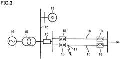
- a model system studied for the simulation is a system in which electric power is transmitted from a power supply 14 through a transformer 15, and it is assumed that a power supply 13 is newly installed on a secondary bus of transformer 15.
- the rated voltage of secondary bus 12 of the transformer was assumed to be 77 kV. It was assumed that three transformers having a rated capacity of 250 MVA were used as transformers 15. It was assumed that transformer 15 had a short-circuit impedance of 22% (based on the self capacity).
- Current-limiting and power-flow control device 10 is installed on a power transmission end of a line extending from bus 12 to a power transmission line 16. Namely, bus 12 and power transmission line 16 including two lines are connected to each other through current-limiting and power-flow control device 10.
- the transmission line had a relatively large capacity among those applied as power transmission lines for 77 kV, and it was assumed that the regular capacity of one line determined by thermal conditions was 170 MW.
- the transmitted power as an index for the sake of the stability should be 80 MW or less (per line). Power transmission of 160 MW is therefore possible even through a single line, as long as 50% of a line reactance X1 (50 km) is compensated for.
- Capacitive reactance Xc of series capacitor 1 of current-limiting and power-flow control device 10 and inductive reactance XL of reactor 2 thereof were studied in the following way.
- the steady-state current flowing in series capacitor 1 and reactor 2 in the case of the parallel LC type, the current flowing in series capacitor 1 and reactor 2 of current-limiting and power-flow control device 10 increases relative to the line current, which causes an increase of the device cost.
- the steady-state current flowing in series capacitor 1 and reactor 2 in the case of power transmission through the two lines was set to twice or less as high as the line current.
- inductive reactance XL of reactor 2 necessary for suppressing short-circuit current was studied.
- the study was conducted of suppression of fault current to 30 kA or less when three-phase short circuit occurs at a fault point 17 in Fig. 3 to thereby cause the current value to become maximum.
- the characteristics of current-limiting and power-flow control device 10 satisfying this condition were determined in the following way.
- Inductive reactance XL of reactor 2 is therefore 0.046 pu or more.
- the current at the start of operation of superconducting current-limiting element 8 in current-limiting and power-flow control device 10 was assumed to be 4800A rms (6.7 kAp). This value is twice as large as the steady-state current (2400A) flowing in the superconducting current-limiting element. Further, the current-limiting resistance in the normal conducting state of superconducting current-limiting element 8 was assumed to be 8 ⁇ .
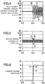
- Figs. 4 to 6 show the results of a simulation to which current-limiting and power-flow control device 10 of the present invention is applied.
- the horizontal axis of each graph represents time.
- the vertical axis of the graph in Fig. 4 represents the fault current (passing current in the current-limiting and power-flow control device), and the unit of the fault current is kA.
- the vertical axis in Fig. 5 represents the voltage across the terminals of the series capacitor in current-limiting and power-flow control device 10, and the unit of the voltage is kV.
- the vertical axis in Fig. 6 represents the current-limiting resistance, and the unit of the resistance is ⁇ .
- Fig. 4 shows the results of a simulation to which current-limiting and power-flow control device 10 of the present invention is applied.
- the horizontal axis of each graph represents time.
- the vertical axis of the graph in Fig. 4 represents the fault current (passing current in the current-limiting and power-flow control device), and the unit of the fault current
- the magnitude of the voltage across the terminals of series capacitor 1 in current-limiting and power-flow control device 10 at the time of occurrence of a fault is an excessive voltage of approximately 3.2 pu at a half wave immediately after the fault, due to an influence of a slight operation delay of the current limiter for example.
- the voltage is thereafter suppressed to substantially the same extent as the steady-state voltage.
- superconducting current-limiting element 8 which exhibits an autonomous and rapid current-limiting effect is applied to current-limiting and power-flow control device 10 to thereby eliminate the need for installation of an arrester for the sake of protecting series capacitor 1 from an excessive voltage across the terminals, and also eliminate the need for a bypass switch operation for bypassing series capacitor 1 at the time of occurrence of a fault.
- the present invention is particularly advantageously applied to a current-limiting and power-flow control device including a superconducting current-limiting element.
Landscapes
- Engineering & Computer Science (AREA)
- Power Engineering (AREA)
- Emergency Protection Circuit Devices (AREA)
- Containers, Films, And Cooling For Superconductive Devices (AREA)
Claims (2)
- Strombegrenzungs- und Leistungsflusssteuervorrichtung (10), bei der ein Supraleiter zur Strombegrenzung mittels Übergang von einem supraleitenden Zustand in einen normalleitenden Zustand, der von einem Überstrom ausgelöst wird, verwendet wird, umfassend:- ein supraleitendes Strombegrenzungselement (8), das den Supraleiter aufweist,- einen Kondensator (1), der mit dem supraleitenden Strombegrenzungselement (8) in Reihe geschaltet ist, und- eine Parallelschaltung mit einer Drossel (2), die parallel mit einer Reihenschaltung geschaltet ist, die das supraleitende Strombegrenzungselement (8) und den Kondensator (1) aufweist und entweder einen Thyristorschalter (4) oder eine angeschlossene Drossel (9), die mit der Drossel (2) in Reihe geschaltet ist, aufweist,dadurch gekennzeichnet, dass
die Strombegrenzungs- und Leistungsflusssteuervorrichtung (10) eine Steuerschaltung (5) umfasst, die dazu ausgelegt ist, den Thyristorschalter (4) oder die angeschlossene Drossel (9) zu steuern, so dass die in der Parallelschaltung vorgesehene Drossel (2) als Strombegrenzungsdrossel und zum Begrenzen des Überstroms nach dem Übergang dient, um eine Wiederherstellung des Strombegrenzungselements (8) in den supraleitenden Zustand des Supraleiters zu erlauben. - Verfahren zum Betrieb der Strombegrenzungs- und Leistungsflusssteuervorrichtung (10) nach Anspruch 1 zur Strombegrenzung mittels Übergang von einem supraleitenden Zustand in einen normalleitenden Zustand, der von einem Überstrom ausgelöst wird, zur automatischen Durchführung eines Strombegrenzungsvorgangs,
gekennzeichnet durch
Umschalten der die Drossel (2) aufweisenden Parallelschaltung nach diesem Strombegrenzungsvorgang auf Stromfluss, um das supraleitende Strombegrenzungselement (8) zu umgehen, um zum Wiederherstellen des Strombegrenzungselements (8) in den supraleitenden Zustand entsprechend der Steuerung der Steuerschaltung (5) den Überstrom zu begrenzen.
Applications Claiming Priority (2)
| Application Number | Priority Date | Filing Date | Title |
|---|---|---|---|
| JP2013075938A JP2014204460A (ja) | 2013-04-01 | 2013-04-01 | 限流・潮流制御装置 |
| PCT/JP2014/058535 WO2014162949A1 (ja) | 2013-04-01 | 2014-03-26 | 限流・潮流制御装置 |
Publications (3)
| Publication Number | Publication Date |
|---|---|
| EP2983263A1 EP2983263A1 (de) | 2016-02-10 |
| EP2983263A4 EP2983263A4 (de) | 2017-01-11 |
| EP2983263B1 true EP2983263B1 (de) | 2019-11-06 |
Family
ID=51658247
Family Applications (1)
| Application Number | Title | Priority Date | Filing Date |
|---|---|---|---|
| EP14779757.5A Active EP2983263B1 (de) | 2013-04-01 | 2014-03-26 | Strombegrenzungs-/-flusssteuerungsvorrichtung |
Country Status (7)
| Country | Link |
|---|---|
| US (1) | US9762051B2 (de) |
| EP (1) | EP2983263B1 (de) |
| JP (1) | JP2014204460A (de) |
| KR (1) | KR20150136534A (de) |
| CN (1) | CN105103397B (de) |
| ES (1) | ES2759913T3 (de) |
| WO (1) | WO2014162949A1 (de) |
Families Citing this family (6)
| Publication number | Priority date | Publication date | Assignee | Title |
|---|---|---|---|---|
| JP6069073B2 (ja) * | 2013-04-01 | 2017-01-25 | 住友電気工業株式会社 | 限流装置 |
| KR101622187B1 (ko) * | 2014-05-13 | 2016-05-18 | 엘에스산전 주식회사 | 한류기 |
| KR102077528B1 (ko) * | 2019-07-11 | 2020-02-14 | 아이에프텍(주) | Iot 기반의 무정전 전원 공급 장치의 연결 구조 및 그 제어 방법 |
| CN111541231A (zh) * | 2020-05-19 | 2020-08-14 | 中天集团上海超导技术有限公司 | 一种增强三相同轴式超导电缆抗故障电流能力的方法 |
| CN112165078B (zh) * | 2020-06-15 | 2022-07-05 | 国网湖北省电力有限公司黄冈供电公司 | 一种利用短路电流变化率的谐振型限流器投入控制方法 |
| CN121529460B (zh) * | 2026-01-15 | 2026-04-10 | 杭州布雷科电气有限公司 | 基于igbt和接触器的可切换串并联限流电路的离散组合优化控制方法 |
Family Cites Families (22)
| Publication number | Priority date | Publication date | Assignee | Title |
|---|---|---|---|---|
| DE1932379C3 (de) * | 1969-06-26 | 1978-05-11 | Siemens Ag, 1000 Berlin Und 8000 Muenchen | Spule mit veränderlicher Induktivität als Strombegrenzungseinrichtung für Energieübertragungsanlagen |
| JP2901068B2 (ja) | 1988-10-07 | 1999-06-02 | 株式会社東芝 | 限流装置 |
| JPH02116184A (ja) * | 1988-10-26 | 1990-04-27 | Toshiba Corp | パルスレーザ電源装置 |
| JP2941833B2 (ja) | 1989-01-27 | 1999-08-30 | 株式会社東芝 | 超電導限流装置 |
| JPH03245725A (ja) | 1990-02-22 | 1991-11-01 | Takaoka Electric Mfg Co Ltd | 過電流限流装置 |
| JP2947927B2 (ja) * | 1990-11-30 | 1999-09-13 | 東京電力株式会社 | 超電導限流装置 |
| JPH07209371A (ja) * | 1994-01-21 | 1995-08-11 | Fuji Electric Co Ltd | ケーブルの交流耐電圧試験装置および方法 |
| JPH0974682A (ja) * | 1995-09-04 | 1997-03-18 | Hitachi Ltd | 直列コンデンサ制御装置 |
| JP2850810B2 (ja) * | 1995-11-01 | 1999-01-27 | 日新電機株式会社 | 超電導限流装置 |
| JPH11146555A (ja) * | 1997-11-05 | 1999-05-28 | Toshiba Corp | 超電導限流装置 |
| JP2000090788A (ja) | 1998-09-09 | 2000-03-31 | Toshiba Corp | 限流装置及び限流遮断装置 |
| JP2001078362A (ja) * | 1999-09-07 | 2001-03-23 | Toshiba Corp | 電力系統安定化装置 |
| DE19963181C2 (de) | 1999-12-27 | 2002-04-18 | Siemens Ag | Resistive Strombegrenzereinrichtung für Gleich- oder Wechselstrom mit wenigstens einer Leiterbahn mit Hoch-T¶c¶-Supraleitermaterial |
| JP2004350337A (ja) * | 2003-05-20 | 2004-12-09 | National Institute Of Advanced Industrial & Technology | 限流機能付き潮流制御装置 |
| JP4851814B2 (ja) * | 2006-03-01 | 2012-01-11 | 株式会社東芝 | 電力システム |
| KR100780706B1 (ko) * | 2006-08-17 | 2007-11-30 | 엘에스산전 주식회사 | 복합형 초전도 한류기 |
| US20080056327A1 (en) * | 2006-08-30 | 2008-03-06 | Hatch Ltd. | Method and system for predictive electrode lowering in a furnace |
| KR100888147B1 (ko) | 2007-08-20 | 2009-03-13 | 한국전력공사 | 하이브리드 초전도 한류기 |
| CN101183129A (zh) | 2007-11-26 | 2008-05-21 | 天津理工大学 | 一种失超型超导故障限流器的故障检测系统及其检测方法 |
| JP5187750B2 (ja) * | 2008-07-04 | 2013-04-24 | 株式会社前川製作所 | 磁気飽和型限流器 |
| CN102035196A (zh) * | 2010-12-30 | 2011-04-27 | 东南大学 | 一种基于可控串补的故障限流装置 |
| CN102646968B (zh) * | 2012-05-04 | 2015-03-18 | 中国科学院电工研究所 | 一种电抗器型短路故障限流器 |
-
2013
- 2013-04-01 JP JP2013075938A patent/JP2014204460A/ja active Pending
-
2014
- 2014-03-26 CN CN201480019156.2A patent/CN105103397B/zh not_active Expired - Fee Related
- 2014-03-26 EP EP14779757.5A patent/EP2983263B1/de active Active
- 2014-03-26 ES ES14779757T patent/ES2759913T3/es active Active
- 2014-03-26 WO PCT/JP2014/058535 patent/WO2014162949A1/ja not_active Ceased
- 2014-03-26 US US14/770,998 patent/US9762051B2/en not_active Expired - Fee Related
- 2014-03-26 KR KR1020157031202A patent/KR20150136534A/ko not_active Ceased
Non-Patent Citations (1)
| Title |
|---|
| None * |
Also Published As
| Publication number | Publication date |
|---|---|
| CN105103397A (zh) | 2015-11-25 |
| EP2983263A4 (de) | 2017-01-11 |
| KR20150136534A (ko) | 2015-12-07 |
| CN105103397B (zh) | 2019-01-11 |
| JP2014204460A (ja) | 2014-10-27 |
| US9762051B2 (en) | 2017-09-12 |
| ES2759913T3 (es) | 2020-05-12 |
| EP2983263A1 (de) | 2016-02-10 |
| US20160020604A1 (en) | 2016-01-21 |
| WO2014162949A1 (ja) | 2014-10-09 |
Similar Documents
| Publication | Publication Date | Title |
|---|---|---|
| EP2983263B1 (de) | Strombegrenzungs-/-flusssteuerungsvorrichtung | |
| WO2019119886A1 (zh) | 一种串联补偿器及控制方法 | |
| Kuchanskyy | Application of controlled shunt reactors for suppression abnormal resonance overvoltages in assymetric modes | |
| KR101673956B1 (ko) | 전력계통을 보호하기 위한 복합형 초전도 한류기 및 이를 포함하는 차단기 시스템 | |
| US7605499B2 (en) | Systems and methods of dynamic reactive support for a power transmission system | |
| Župan et al. | Transients caused by switching of 420 kV three-phase variable shunt reactor | |
| US10218170B2 (en) | Current-limiting device utilizing a superconductor for a current-limiting operation | |
| CA2753992C (en) | Poly-phase reactive power compensator | |
| Wu et al. | Research on current limiting solid state circuit breaker for DC microgrid | |
| CN101646985A (zh) | 用于缓解动态过电压的方法和装置 | |
| Panasetsky et al. | On the problem of shunt reactor tripping during single-and three-phase auto-reclosing | |
| CN103280819B (zh) | 一种变电站的并联电抗器补偿回路及其补偿方法 | |
| Ben-Ashour et al. | Transient overvoltages protection for series capacitors in compensated transmission lines | |
| Golshani et al. | Facts based fault current limiter utilization in HV grid | |
| Boribun et al. | Comparative study on a fault current limiter with thyristor-controlled impedances | |
| KR20090120766A (ko) | 전력계통의 중성선에 초전도 전류제한기의 적용을 통한고장전류 제한 방법 | |
| CN221177278U (zh) | 单相接地故障处理系统 | |
| Kowalski et al. | Application of static var compensation on the southern california edison system to improve transmission system capacity and address voltage stability issues-part 1. planning, design and performance criteria considerations | |
| Filipović-Grčić et al. | Transients caused by switching of 420 kV three-phase variable shunt reactor | |
| Zeng et al. | Investigation on Internal Overvoltage Performance of EHV Multi-Break Circuit Breaker | |
| Patcharoen et al. | Inrush current analysis for switching large shunt capacitor bank in a 230 kV substation system | |
| An et al. | HVDC Scheme’s Dynamic/Transient Responses to AC and DC Faults | |
| Klucznik et al. | Resonance problems in UHV transmission lines | |
| WO2000052805A1 (en) | Temporary overvoltage limiter for high voltage transmission systems | |
| Bahrami | An integrated control scheme for dynamic voltage restorer to limit downstream fault currents |
Legal Events
| Date | Code | Title | Description |
|---|---|---|---|
| PUAI | Public reference made under article 153(3) epc to a published international application that has entered the european phase |
Free format text: ORIGINAL CODE: 0009012 |
|
| 17P | Request for examination filed |
Effective date: 20151021 |
|
| AK | Designated contracting states |
Kind code of ref document: A1 Designated state(s): AL AT BE BG CH CY CZ DE DK EE ES FI FR GB GR HR HU IE IS IT LI LT LU LV MC MK MT NL NO PL PT RO RS SE SI SK SM TR |
|
| AX | Request for extension of the european patent |
Extension state: BA ME |
|
| DAX | Request for extension of the european patent (deleted) | ||
| A4 | Supplementary search report drawn up and despatched |
Effective date: 20161209 |
|
| RIC1 | Information provided on ipc code assigned before grant |
Ipc: H02H 9/02 20060101AFI20161205BHEP Ipc: H02H 3/08 20060101ALI20161205BHEP |
|
| STAA | Information on the status of an ep patent application or granted ep patent |
Free format text: STATUS: EXAMINATION IS IN PROGRESS |
|
| 17Q | First examination report despatched |
Effective date: 20181019 |
|
| GRAP | Despatch of communication of intention to grant a patent |
Free format text: ORIGINAL CODE: EPIDOSNIGR1 |
|
| STAA | Information on the status of an ep patent application or granted ep patent |
Free format text: STATUS: GRANT OF PATENT IS INTENDED |
|
| INTG | Intention to grant announced |
Effective date: 20190606 |
|
| GRAS | Grant fee paid |
Free format text: ORIGINAL CODE: EPIDOSNIGR3 |
|
| GRAA | (expected) grant |
Free format text: ORIGINAL CODE: 0009210 |
|
| STAA | Information on the status of an ep patent application or granted ep patent |
Free format text: STATUS: THE PATENT HAS BEEN GRANTED |
|
| AK | Designated contracting states |
Kind code of ref document: B1 Designated state(s): AL AT BE BG CH CY CZ DE DK EE ES FI FR GB GR HR HU IE IS IT LI LT LU LV MC MK MT NL NO PL PT RO RS SE SI SK SM TR |
|
| REG | Reference to a national code |
Ref country code: GB Ref legal event code: FG4D |
|
| REG | Reference to a national code |
Ref country code: CH Ref legal event code: EP Ref country code: AT Ref legal event code: REF Ref document number: 1200094 Country of ref document: AT Kind code of ref document: T Effective date: 20191115 |
|
| REG | Reference to a national code |
Ref country code: DE Ref legal event code: R096 Ref document number: 602014056354 Country of ref document: DE |
|
| REG | Reference to a national code |
Ref country code: IE Ref legal event code: FG4D |
|
| REG | Reference to a national code |
Ref country code: NL Ref legal event code: MP Effective date: 20191106 |
|
| REG | Reference to a national code |
Ref country code: LT Ref legal event code: MG4D |
|
| PG25 | Lapsed in a contracting state [announced via postgrant information from national office to epo] |
Ref country code: PT Free format text: LAPSE BECAUSE OF FAILURE TO SUBMIT A TRANSLATION OF THE DESCRIPTION OR TO PAY THE FEE WITHIN THE PRESCRIBED TIME-LIMIT Effective date: 20200306 Ref country code: FI Free format text: LAPSE BECAUSE OF FAILURE TO SUBMIT A TRANSLATION OF THE DESCRIPTION OR TO PAY THE FEE WITHIN THE PRESCRIBED TIME-LIMIT Effective date: 20191106 Ref country code: LV Free format text: LAPSE BECAUSE OF FAILURE TO SUBMIT A TRANSLATION OF THE DESCRIPTION OR TO PAY THE FEE WITHIN THE PRESCRIBED TIME-LIMIT Effective date: 20191106 Ref country code: SE Free format text: LAPSE BECAUSE OF FAILURE TO SUBMIT A TRANSLATION OF THE DESCRIPTION OR TO PAY THE FEE WITHIN THE PRESCRIBED TIME-LIMIT Effective date: 20191106 Ref country code: BG Free format text: LAPSE BECAUSE OF FAILURE TO SUBMIT A TRANSLATION OF THE DESCRIPTION OR TO PAY THE FEE WITHIN THE PRESCRIBED TIME-LIMIT Effective date: 20200206 Ref country code: PL Free format text: LAPSE BECAUSE OF FAILURE TO SUBMIT A TRANSLATION OF THE DESCRIPTION OR TO PAY THE FEE WITHIN THE PRESCRIBED TIME-LIMIT Effective date: 20191106 Ref country code: LT Free format text: LAPSE BECAUSE OF FAILURE TO SUBMIT A TRANSLATION OF THE DESCRIPTION OR TO PAY THE FEE WITHIN THE PRESCRIBED TIME-LIMIT Effective date: 20191106 Ref country code: NO Free format text: LAPSE BECAUSE OF FAILURE TO SUBMIT A TRANSLATION OF THE DESCRIPTION OR TO PAY THE FEE WITHIN THE PRESCRIBED TIME-LIMIT Effective date: 20200206 Ref country code: GR Free format text: LAPSE BECAUSE OF FAILURE TO SUBMIT A TRANSLATION OF THE DESCRIPTION OR TO PAY THE FEE WITHIN THE PRESCRIBED TIME-LIMIT Effective date: 20200207 Ref country code: NL Free format text: LAPSE BECAUSE OF FAILURE TO SUBMIT A TRANSLATION OF THE DESCRIPTION OR TO PAY THE FEE WITHIN THE PRESCRIBED TIME-LIMIT Effective date: 20191106 |
|
| PGFP | Annual fee paid to national office [announced via postgrant information from national office to epo] |
Ref country code: IT Payment date: 20200221 Year of fee payment: 7 Ref country code: DE Payment date: 20200310 Year of fee payment: 7 Ref country code: GB Payment date: 20200318 Year of fee payment: 7 |
|
| REG | Reference to a national code |
Ref country code: ES Ref legal event code: FG2A Ref document number: 2759913 Country of ref document: ES Kind code of ref document: T3 Effective date: 20200512 |
|
| PG25 | Lapsed in a contracting state [announced via postgrant information from national office to epo] |
Ref country code: HR Free format text: LAPSE BECAUSE OF FAILURE TO SUBMIT A TRANSLATION OF THE DESCRIPTION OR TO PAY THE FEE WITHIN THE PRESCRIBED TIME-LIMIT Effective date: 20191106 Ref country code: IS Free format text: LAPSE BECAUSE OF FAILURE TO SUBMIT A TRANSLATION OF THE DESCRIPTION OR TO PAY THE FEE WITHIN THE PRESCRIBED TIME-LIMIT Effective date: 20200306 Ref country code: RS Free format text: LAPSE BECAUSE OF FAILURE TO SUBMIT A TRANSLATION OF THE DESCRIPTION OR TO PAY THE FEE WITHIN THE PRESCRIBED TIME-LIMIT Effective date: 20191106 |
|
| PG25 | Lapsed in a contracting state [announced via postgrant information from national office to epo] |
Ref country code: AL Free format text: LAPSE BECAUSE OF FAILURE TO SUBMIT A TRANSLATION OF THE DESCRIPTION OR TO PAY THE FEE WITHIN THE PRESCRIBED TIME-LIMIT Effective date: 20191106 |
|
| PG25 | Lapsed in a contracting state [announced via postgrant information from national office to epo] |
Ref country code: EE Free format text: LAPSE BECAUSE OF FAILURE TO SUBMIT A TRANSLATION OF THE DESCRIPTION OR TO PAY THE FEE WITHIN THE PRESCRIBED TIME-LIMIT Effective date: 20191106 Ref country code: DK Free format text: LAPSE BECAUSE OF FAILURE TO SUBMIT A TRANSLATION OF THE DESCRIPTION OR TO PAY THE FEE WITHIN THE PRESCRIBED TIME-LIMIT Effective date: 20191106 Ref country code: RO Free format text: LAPSE BECAUSE OF FAILURE TO SUBMIT A TRANSLATION OF THE DESCRIPTION OR TO PAY THE FEE WITHIN THE PRESCRIBED TIME-LIMIT Effective date: 20191106 Ref country code: CZ Free format text: LAPSE BECAUSE OF FAILURE TO SUBMIT A TRANSLATION OF THE DESCRIPTION OR TO PAY THE FEE WITHIN THE PRESCRIBED TIME-LIMIT Effective date: 20191106 |
|
| PGFP | Annual fee paid to national office [announced via postgrant information from national office to epo] |
Ref country code: ES Payment date: 20200401 Year of fee payment: 7 |
|
| REG | Reference to a national code |
Ref country code: DE Ref legal event code: R097 Ref document number: 602014056354 Country of ref document: DE |
|
| REG | Reference to a national code |
Ref country code: AT Ref legal event code: MK05 Ref document number: 1200094 Country of ref document: AT Kind code of ref document: T Effective date: 20191106 |
|
| PG25 | Lapsed in a contracting state [announced via postgrant information from national office to epo] |
Ref country code: SM Free format text: LAPSE BECAUSE OF FAILURE TO SUBMIT A TRANSLATION OF THE DESCRIPTION OR TO PAY THE FEE WITHIN THE PRESCRIBED TIME-LIMIT Effective date: 20191106 Ref country code: SK Free format text: LAPSE BECAUSE OF FAILURE TO SUBMIT A TRANSLATION OF THE DESCRIPTION OR TO PAY THE FEE WITHIN THE PRESCRIBED TIME-LIMIT Effective date: 20191106 |
|
| PLBE | No opposition filed within time limit |
Free format text: ORIGINAL CODE: 0009261 |
|
| STAA | Information on the status of an ep patent application or granted ep patent |
Free format text: STATUS: NO OPPOSITION FILED WITHIN TIME LIMIT |
|
| 26N | No opposition filed |
Effective date: 20200807 |
|
| PG25 | Lapsed in a contracting state [announced via postgrant information from national office to epo] |
Ref country code: MC Free format text: LAPSE BECAUSE OF FAILURE TO SUBMIT A TRANSLATION OF THE DESCRIPTION OR TO PAY THE FEE WITHIN THE PRESCRIBED TIME-LIMIT Effective date: 20191106 |
|
| REG | Reference to a national code |
Ref country code: CH Ref legal event code: PL |
|
| PG25 | Lapsed in a contracting state [announced via postgrant information from national office to epo] |
Ref country code: AT Free format text: LAPSE BECAUSE OF FAILURE TO SUBMIT A TRANSLATION OF THE DESCRIPTION OR TO PAY THE FEE WITHIN THE PRESCRIBED TIME-LIMIT Effective date: 20191106 Ref country code: SI Free format text: LAPSE BECAUSE OF FAILURE TO SUBMIT A TRANSLATION OF THE DESCRIPTION OR TO PAY THE FEE WITHIN THE PRESCRIBED TIME-LIMIT Effective date: 20191106 |
|
| REG | Reference to a national code |
Ref country code: BE Ref legal event code: MM Effective date: 20200331 |
|
| PG25 | Lapsed in a contracting state [announced via postgrant information from national office to epo] |
Ref country code: LU Free format text: LAPSE BECAUSE OF NON-PAYMENT OF DUE FEES Effective date: 20200326 |
|
| PG25 | Lapsed in a contracting state [announced via postgrant information from national office to epo] |
Ref country code: LI Free format text: LAPSE BECAUSE OF NON-PAYMENT OF DUE FEES Effective date: 20200331 Ref country code: FR Free format text: LAPSE BECAUSE OF NON-PAYMENT OF DUE FEES Effective date: 20200331 Ref country code: CH Free format text: LAPSE BECAUSE OF NON-PAYMENT OF DUE FEES Effective date: 20200331 Ref country code: IE Free format text: LAPSE BECAUSE OF NON-PAYMENT OF DUE FEES Effective date: 20200326 |
|
| PG25 | Lapsed in a contracting state [announced via postgrant information from national office to epo] |
Ref country code: BE Free format text: LAPSE BECAUSE OF NON-PAYMENT OF DUE FEES Effective date: 20200331 |
|
| REG | Reference to a national code |
Ref country code: DE Ref legal event code: R119 Ref document number: 602014056354 Country of ref document: DE |
|
| GBPC | Gb: european patent ceased through non-payment of renewal fee |
Effective date: 20210326 |
|
| PG25 | Lapsed in a contracting state [announced via postgrant information from national office to epo] |
Ref country code: GB Free format text: LAPSE BECAUSE OF NON-PAYMENT OF DUE FEES Effective date: 20210326 Ref country code: DE Free format text: LAPSE BECAUSE OF NON-PAYMENT OF DUE FEES Effective date: 20211001 |
|
| PG25 | Lapsed in a contracting state [announced via postgrant information from national office to epo] |
Ref country code: IT Free format text: LAPSE BECAUSE OF NON-PAYMENT OF DUE FEES Effective date: 20210326 |
|
| PG25 | Lapsed in a contracting state [announced via postgrant information from national office to epo] |
Ref country code: TR Free format text: LAPSE BECAUSE OF FAILURE TO SUBMIT A TRANSLATION OF THE DESCRIPTION OR TO PAY THE FEE WITHIN THE PRESCRIBED TIME-LIMIT Effective date: 20191106 Ref country code: MT Free format text: LAPSE BECAUSE OF FAILURE TO SUBMIT A TRANSLATION OF THE DESCRIPTION OR TO PAY THE FEE WITHIN THE PRESCRIBED TIME-LIMIT Effective date: 20191106 Ref country code: CY Free format text: LAPSE BECAUSE OF FAILURE TO SUBMIT A TRANSLATION OF THE DESCRIPTION OR TO PAY THE FEE WITHIN THE PRESCRIBED TIME-LIMIT Effective date: 20191106 |
|
| PG25 | Lapsed in a contracting state [announced via postgrant information from national office to epo] |
Ref country code: MK Free format text: LAPSE BECAUSE OF FAILURE TO SUBMIT A TRANSLATION OF THE DESCRIPTION OR TO PAY THE FEE WITHIN THE PRESCRIBED TIME-LIMIT Effective date: 20191106 |
|
| REG | Reference to a national code |
Ref country code: ES Ref legal event code: FD2A Effective date: 20220630 |
|
| PG25 | Lapsed in a contracting state [announced via postgrant information from national office to epo] |
Ref country code: ES Free format text: LAPSE BECAUSE OF NON-PAYMENT OF DUE FEES Effective date: 20210327 |