EP2983274B1 - Litzenquerschnittvariationen zum erhöhen des füllfaktor elektromaschinenwindungsnuten - Google Patents
Litzenquerschnittvariationen zum erhöhen des füllfaktor elektromaschinenwindungsnuten Download PDFInfo
- Publication number
- EP2983274B1 EP2983274B1 EP15170719.7A EP15170719A EP2983274B1 EP 2983274 B1 EP2983274 B1 EP 2983274B1 EP 15170719 A EP15170719 A EP 15170719A EP 2983274 B1 EP2983274 B1 EP 2983274B1
- Authority
- EP
- European Patent Office
- Prior art keywords
- conductor
- slot
- conductor strands
- cross
- winding
- Prior art date
- Legal status (The legal status is an assumption and is not a legal conclusion. Google has not performed a legal analysis and makes no representation as to the accuracy of the status listed.)
- Not-in-force
Links
Images



Classifications
-
- H—ELECTRICITY
- H02—GENERATION; CONVERSION OR DISTRIBUTION OF ELECTRIC POWER
- H02K—DYNAMO-ELECTRIC MACHINES
- H02K3/00—Details of windings
- H02K3/04—Windings characterised by the conductor shape, form or construction, e.g. with bar conductors
- H02K3/12—Windings characterised by the conductor shape, form or construction, e.g. with bar conductors arranged in slots
-
- H—ELECTRICITY
- H02—GENERATION; CONVERSION OR DISTRIBUTION OF ELECTRIC POWER
- H02K—DYNAMO-ELECTRIC MACHINES
- H02K15/00—Processes or apparatus specially adapted for manufacturing, assembling, maintaining or repairing of dynamo-electric machines
- H02K15/04—Processes or apparatus specially adapted for manufacturing, assembling, maintaining or repairing of dynamo-electric machines of windings prior to their mounting into the machines
-
- H—ELECTRICITY
- H02—GENERATION; CONVERSION OR DISTRIBUTION OF ELECTRIC POWER
- H02K—DYNAMO-ELECTRIC MACHINES
- H02K15/00—Processes or apparatus specially adapted for manufacturing, assembling, maintaining or repairing of dynamo-electric machines
- H02K15/08—Forming windings by laying conductors into or around core parts
- H02K15/085—Forming windings by laying conductors into or around core parts by laying conductors into slotted stators
-
- H—ELECTRICITY
- H02—GENERATION; CONVERSION OR DISTRIBUTION OF ELECTRIC POWER
- H02K—DYNAMO-ELECTRIC MACHINES
- H02K3/00—Details of windings
- H02K3/02—Windings characterised by the conductor material
-
- H—ELECTRICITY
- H02—GENERATION; CONVERSION OR DISTRIBUTION OF ELECTRIC POWER
- H02K—DYNAMO-ELECTRIC MACHINES
- H02K3/00—Details of windings
- H02K3/04—Windings characterised by the conductor shape, form or construction, e.g. with bar conductors
- H02K3/24—Windings characterised by the conductor shape, form or construction, e.g. with bar conductors with channels or ducts for cooling medium between the conductors
-
- H—ELECTRICITY
- H02—GENERATION; CONVERSION OR DISTRIBUTION OF ELECTRIC POWER
- H02K—DYNAMO-ELECTRIC MACHINES
- H02K3/00—Details of windings
- H02K3/30—Windings characterised by the insulating material
-
- H—ELECTRICITY
- H02—GENERATION; CONVERSION OR DISTRIBUTION OF ELECTRIC POWER
- H02K—DYNAMO-ELECTRIC MACHINES
- H02K3/00—Details of windings
- H02K3/32—Windings characterised by the shape, form or construction of the insulation
- H02K3/34—Windings characterised by the shape, form or construction of the insulation between conductors or between conductor and core, e.g. slot insulation
-
- H—ELECTRICITY
- H02—GENERATION; CONVERSION OR DISTRIBUTION OF ELECTRIC POWER
- H02K—DYNAMO-ELECTRIC MACHINES
- H02K3/00—Details of windings
- H02K3/32—Windings characterised by the shape, form or construction of the insulation
- H02K3/34—Windings characterised by the shape, form or construction of the insulation between conductors or between conductor and core, e.g. slot insulation
- H02K3/345—Windings characterised by the shape, form or construction of the insulation between conductors or between conductor and core, e.g. slot insulation between conductor and core, e.g. slot insulation
Definitions
- the subject matter disclosed herein relates to the field of electric machines and other electromagnetic devices, and to strand cross-sections and stacked conducting strands for high fill-factor electric machine windings.
- Slot fill factor of a stator winding placed inside a stator slot is a critical design parameter for achieving higher power densities.
- Slot fill factor is defined as a portion of a slot cross-section in a stator that is occupied by a conductive material, typically copper wire.
- Conventional electric machines use individual wires, which can have a circular- or a rectangular cross-section.
- one cross-section shape of conductor strand e.g. circle
- an effective conductor fill-factor for a distributed winding is in the range of about 30 percent to about 40 percent and the effective conductor fill-factor for a concentrated winding is in the range of about 50 percent to about 60 percent.
- windings use numerous small solid section strands whose cross-sectional dimensions are limited and decided by the skin effect and proximity effect.
- Use of numerous strands of individually small cross-sectional area maximizes the combined current-carrying conductor cross section in the slot.
- Having many strands of small cross-section area maximizes the effective current-carrying cross section.
- An electric machine winding that can use shape-conforming conductors to increase slot fill factor is desired.
- US2014/035423A1 describes the production of electric machines such as induction motors or generators.
- the winding slot includes a slot cavity with a cross-section area and the plurality of distributed conductor strands are configured to maximize slot fill factor.
- the conductor strands and its associated insulator can be manufactured through additive manufacturing or conventional methods that facilitate filling the slot with the conductor strands and insulator.
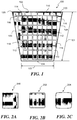
- FIG. 1 depicts an exemplary winding arrangement of manifold conductor strands in a slot of a stator of an electric machine, e.g., an electric motor in accordance with an example.
- a total cross-section area of slot 100 has a trapezoidal shape and can include manifold conductor strands of various cross-sectional shapes that are arranged orthogonally to the plane of the slot cross-section area (i.e., with cross sectional shapes 112 stacked along both dimension 101 and dimension 103 of the slot 100) in order to increase the packing or fill factor of slot 100.
- a trapezoidal cross-section shaped slot 100 is described and shown in FIG. 1
- other slots with square, rectangular, triangular, or polygon cross-sections can also be used in accordance with embodiments of the invention.
- manifold conductor strands can be made from conductive metals such as but not limited to copper, aluminum, silver, or a combination of these conductive metals.
- slot 100 can include substantially similar conductor strands 112 with a substantially similar cross-section area A disposed between slot top or side 102 and slot bottom or side 104 in slot cavity. Conductor strands 112 are packed into slot 100 as tightly as possible and fill as much of the slot cross-section. In gap 110 of slot cavity where conductor strands 112 cannot be placed due to interference with slot walls 106 and 108, other rectangular or polygonal cross-section shaped conductor strands are introduced in order to maximize fill factor of total slot cross-section area.
- slot 100 includes strand 114 with a cross-section area B, strand 116 with a cross-section area C, strand 118 with a cross-section area D, and strand 120 with a cross-section area E.
- Each additional strand 114-120 has a cross-section area that is equal to cross-section area A of strand 112 in order to provide equivalent impedance among all conductor strands.
- An insulation matrix is used between each strand 112-120 that insulates each conductor strand and prevents shorting out of the electric machine.
- the insulation matrix can be made from ceramic, glass, and/or polymers.
- arrangement of conductor strands can be a "basis shape" (e.g., a square cross-section 112 shape of FIG. 1 ) that is used to fill a majority of the volume in gap 110 of slot cavity and using other space-filling cross-section shapes where a basis shape is not used.
- basic shape e.g., a square cross-section 112 shape of FIG. 1
- the conductor strands 112-120 can be manufactured through various manufacturing methodologies.
- a cross-section of a honeycomb structure for the insulation matrix can be made for different types of honeycomb structures, for example, honeycomb structures being regular, irregular, customized, etc.
- the honeycomb structure can be made through extrusion, casting, additive manufacturing, and molten copper can be back-filled in the honeycomb structure to define conductor strands.
- Methods to make the strand layout can include traditional methods of manufacturing by carefully placing these strands shapes together with their insulation and filling the slot appropriately.
- additive manufacturing can be utilized to deposit each of the manifold conductor strands 112-120 of a desired cross-section and the insulation matrix in the slot cavity and within the conductor strands 112-120 in order to provide highly packed conductor strands with good feature control.
- either the conductor or insulator can be separately manufactured initially and then backfilled with the other. Either or both of the conductor and the insulating matrix could be done with additive manufacturing.
- additive manufacturing can be utilized to deposit each of the manifold conductor strands 112-120 of a desired cross-section in the slot cavity and the insulation matrix can be introduced afterward using a process other than additive manufacturing.
- integrated additive manufacturing can be used to incorporate manufacturing of conductor strands that is integrated with manufacturing of the insulation matrix.
- the stator slots may be fabricated individually and then the stator may be assembled with iron core layers or additive manufacturing may be utilized to make the slots and core simultaneously.
- an optimized configuration can include hollow regions at one or more locations within the arrangement of conductor strands, e.g., conductor strands 112-120. These hollow regions can be configured to provide a channel for carrying fluid-based coolant through the slot in order to provide closed loop cooling to each slot. As one or more cooling channels are provided to be immediately adjacent to current carrying conductor strands that generate heat, cooling will be efficient and effective due to being close to the source of the heat.
- conductor strands 112-120 While the arrangement of conductor strands 112-120 has been described in accordance with an exemplary arrangement or packing of conductor strands in a slot 100, it is to be understood that aspects of the invention may include other slot shapes and other conductor strands of any cross-section shape.
- conductor strands e.g., strands 112-120 can include exact polygonal conductor strands as well as conductor strands based on polygons with rounded corners, rounded faces, or other similar rounded features.
- FIG. 2A illustrates an example polygon conductor strand 200 with sharp corners
- FIG. 2B illustrates an example polygon conductor strand 202 shape with rounded corners
- FIG. 2C illustrates an example polygon conductor strand 204 with rounded faces.
- Rounded corners can be introduced to avoid mechanical or thermal stress risers and/or to avoid undesirable electromagnetic effects arising from sharp features. It also increases the insulation thickness and maximizes breakdown strength. Rounding during manufacturing can be produced, for instance, by additive manufacturing.
- other conductor packing schemes are contemplated, depending on application and design strategy.
- the packing arrangement of conductors strands can include conformally-shaped conductor strands immediately adjacent to slot bottom 102 that mimic the shape of arc shaped slot bottom with other polygonal shaped conductor strands with, for example, a rectangular cross-section can be used for achieving a higher fill factor.
- the choice of strand sizes and/or cross-section shapes can also be defined by considering the skin effect inherent to conductors that carry alternating electrical current, as will be described below in FIGS. 4-7E .
- layout of conductor strands described in the enclosed embodiments can also be optimized.
- conductor strand packing in a slot may be determined on the basis of maximizing the fraction of the slot cross section devoted to conductor material subject to the constraints associated with requirements for insulation between strands.
- Slot packing can also be constrained by matching strand cross-section areas and limit aspect ratios to avoid eddy current losses due to slot leakage and other flux components.
- Applicable optimization schemes include, but are not limited to, optimization of size of strands, shape of strands, aspect ratios of strands, number of strands, and optimum combinations of sizes, shape, and number. Tailoring strand shapes provides flexibility in the design of electric machines. Slots can take on any cross-section shape due to the ability to fill such shapes with conductor strands. Also, conductor strand shapes may be informed by conductor pathway planning for electric machine end-turns.
- FIGS. 3A-3E illustrate exemplary cross-section shapes of conductor strands that can be used with the invention while FIG. 3F illustrates an exemplary packing arrangement 312 of slots using more than one type of the polygons of FIGS. 3A-3E .
- a wide variety of polygon cross-section shaped conductor strands can be used to fill the slot 100 including, but not limited to, triangles 302 ( FIG. 3A ), quadrilaterals 304 and 306 ( FIGS. 3B and 3C ), hexagons 308 ( FIG. 3D ), and n-sided concave polygons 310 ( FIG.
- a conductor strand can also include a generic freeform cross section shape.
- FIGS. 4-7E exemplary cross-section shapes of radially stacked conductor strands that leverage the skin effect of current carrying conductors is depicted.
- skin effect limits the AC current to the outer skin (having skin depth ⁇ ) of the conductor strand.
- Literature indicates skin depth can carry a significant percentage of the AC current close to the outer surface of the conductor.
- hollow conductor sections can be utilized as conductor sections that are also more space efficient than solid sections.
- radially stacked conductor strands can be used in accordance with an embodiment of the invention.
- strand assembly 400 includes radially stacked conductor strands 402a, 402b, 402c, and 402d that have a nested configuration with a minimum thin insulation later separating conductor strands 402a-402d (i.e., an inner conductor strand, e.g., strand 402c, is contained within a bore of an outer conductor strand, e.g., conductor strand 402b).
- the nested configuration can be used to mitigate the effects of skin effect.
- Each conductor strand would have the same resistance in the winding.
- slot topology-conforming shapes of radially stacked conductor strands 502a-502d in strand assembly 500 can be utilized in order to mitigate the effects of skin effect as well as provide efficient fill-factor of slot 500. Windings that use radially stacked conductor strands can maximize slot fill factor.
- hollow regions at the center of the radial stack may result in hollow regions at the center of the radial stack, depending on starting shapes utilized and aspect ratios.
- Such hollow regions can be used to provide a channel for fluid-based coolant that provides closed loop cooling to each slot.
- the center conductor strand can be made intentionally hollow and not be a current carrying conductor in order to provide cooling by circulating a fluid-based coolant to remove heat from the slot.
- the cooling channel is provided to be immediately adjacent to the current carrying conductor strands that generate heat, cooling will be efficient and effective due to being close to the source of heat.
- the radially stacked conductor strands for example, radially stacked conductor strands in strand assemblies 400 and 500 can be manufactured through various manufacturing methodologies.
- a cross-section of a honeycomb structure for insulation can be made for different types of honeycomb structures, for example, honeycomb structures being regular, irregular, customized, etc.
- the honeycomb structure can be made through extrusion, casting, or additive manufacturing, and molten copper can be back-filled in the honeycomb structure to define conductor strands, or can include traditional methods of manufacturing by carefully placing these strands shapes and filling the slot appropriately.
- additive manufacturing can be utilized to deposit each of the strand assemblies 400 or 500 of a desired cross-section and insulation, for example, ceramic, glass, and/or polymers between the conductor strands in order to provide highly packed conductor strands with good feature control.
- a desired cross-section and insulation for example, ceramic, glass, and/or polymers between the conductor strands in order to provide highly packed conductor strands with good feature control.
- either the conductor or insulator can be separately manufactured initially and then backfilled with the other. Either or both of the conductor and the insulating matrix could be done with additive manufacturing.
- additive manufacturing can be utilized to deposit each of the manifold conductor strands 112-120 of a desired cross-section in the slot cavity and the insulation matrix can be introduced afterward using a process other than additive manufacturing.
- integrated additive manufacturing can be used to incorporate manufacturing of conductor strands integrated with manufacturing of the insulation matrix.
- Benefits of additive manufacturing include the capability of producing highly packed windings as well as good feature control.
- an optimized configuration can include hollow regions at one or more locations within the arrangement of radially stacked conductor strands.
- conductor strands 502a-502d and insulation matrix can be integrally manufactured with one or more areas being left hollow. These hollow regions can be configured to provide a channel for carrying fluid-based coolant through the slot in order to provide closed loop cooling to each slot.
- cooling channels are provided to be immediately adjacent to the current carrying conductor strands that generate heat, cooling will be efficient and effective due to being close to the source of heat.
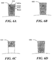
- FIG. 6A illustrates an exemplary coil winding for a single phase AC current
- FIG. 6B illustrates an exemplary coil winding for a dual-phase AC current
- the windings can be composed of multiple radially stacked conductor strands individually acting as turns. As shown in FIG.
- slot-conforming multiple conductor strands can be split to be discontinuous due to design constrains such as, for example, limits on aspect ratio along iron core radius, due to eddy current losses.
- width or thickness of individual conductor strands can be based on near constant cross-sectional area criteria and proximity effect. For example, due to a difference in mean circumference of each conductor strand in a radial direction, in order to keep near constant cross-sectional area in each conductor strand, the outer conductor strands would have to be smaller in thickness as compared to inner conductor strands, For example, in FIG.
- inner conductor strand 602d moving radially from center conductor strand 602d to outer conductor strand 602a, inner conductor strand 602d would have the largest thickness that correspondingly reduces as the slot is traversed radially in direction of arrow 604 to outer conductor strand 602a.
- the mean length travelled by individual conductor strands in a turn, would also be different based on its radial location in the stack. For example, a length travelled by the mean circumference of outer strand 602a would be greater than a length travelled by inner strand 602d, requiring outer strand 602a to be of smaller thickness than the inner strands, in order to maintain the same resistance in each conductor strand.
- radially stacked conductor strands 702, 704, 706, 708, and 710 have various cross-section shapes that can be used in stator slots.
- the remaining slot space can be filled with a variety of conductor strand cross-section shapes without a dominant shape. Limits on aspect ratios can also be selected in order to reduce eddy current losses.
- the cross-section shape of the radially stacked conductor strands in FIGS.6A-7E , number of groups (or turns) of radially stacked conductor strands per phase, number of conductor strands in a radial direction of a turn and thickness of individual conductor strands can also be optimized based on various winding requirements and constraints. Some of the requirements and constraints can include, but are not limited to, skin effect, proximity effect eddy current losses on the surface of individual conductor strands due to slot leakage inductance, voltage requirements, or the like. Additionally, these constraints may be defined by conductor pathway planning for electric machine end-turns.
- Embodiments of the invention disclosed herein for application to electric machines provide increased fill factor of electric machine windings. Using increased portions of the slot enables ultra-power dense electric machines.
Landscapes
- Engineering & Computer Science (AREA)
- Power Engineering (AREA)
- Manufacturing & Machinery (AREA)
- Windings For Motors And Generators (AREA)
Claims (12)
- Wicklungskonfiguration für eine elektrische Maschine, umfassend:einen Statorkern mit einer Vielzahl von Wicklungsschlitzen (100) ;eine Vielzahl von Leiterlitzen (112...), die in einem Wicklungsschlitz (100) der Vielzahl von Wicklungsschlitzen (100) verteilt ist; undeine Isolationsmatrix, die jede der Vielzahl von Leiterlitzen (112...) umgibt;wobei der Wicklungsschlitz (100) einen Schlitzhohlraum mit einem Querschnitt beinhaltet; undwobei die Vielzahl von Leiterlitzen (402; 502; 602; 702...710) dazu konfiguriert ist, radial mit unterschiedlichem Querschnitt gestapelt zu sein; und wobei wenigstens eine von der Isolationsmatrix und der Vielzahl von Leiterlitzen (112...) in dem Schlitzhohlraum durch additive Fertigung aufgebracht ist; und gekennzeichnet durcheine radial innere Leiterlitze (402d; 502d; 602d), die in einer verschachtelten Konfiguration in einer Bohrung einer radial äußeren Leiterlitze (402c; 502c; 602c) enthalten ist.
- Wicklungskonfiguration nach Anspruch 1, wobei jede Leiterlitze (112...) wahlweise aus Kupfer, Aluminium, Silber oder einer Kombination aus Kupfer, Aluminium und Silber besteht.
- Wicklungskonfiguration nach Anspruch 1 oder 2, wobei die Isolationsmatrix wahlweise aus Keramik, Glas, Polymer und einem glasgefüllten Polymer besteht.
- Wicklungskonfiguration nach einem der vorangehenden Ansprüche, wobei die Isolationsmatrix als eine Wabenstruktur konfiguriert ist.
- Wicklungskonfiguration nach Anspruch 4, wobei die Wabenstruktur, die eine jede der Vielzahl von Leiterlitzen (112...) definiert, durch Gießen oder einen anderen Prozess mit einem leitfähigen Material gefüllt wird.
- Wicklungskonfiguration nach einem der vorangehenden Ansprüche, wobei eine jede der Vielzahl von Leiterlitzen (112...) orthogonal zum Querschnitt angeordnet ist, um den Schlitzfüllfaktor zu definieren.
- Wicklungskonfiguration nach einem der vorangehenden Ansprüche, wobei die Vielzahl von Leiterlitzen dazu konfiguriert ist, radial gestapelt zu sein, wobei jede radial gestapelte Leiterlitze als eine Windung dient.
- Wicklung der Konfiguration nach Anspruch 7, wobei die radiale Stapelung dazu konfiguriert ist, der Schlitztopologie zu entsprechen.
- Wicklungskonfiguration nach einem der vorangehenden Ansprüche, wobei wenigstens eine der Vielzahl von Leiterlitzen (112...) einen Querschnitt beinhaltet, der ausgewählt ist aus einem von einem Dreieck, einem Trapez, einem Vierseiter, einem konkaven Vieleck oder einer allgemeinen Freiformquerschnittform.
- Wicklungskonfiguration nach einem der vorangehenden Ansprüche, wobei eine der Vielzahl von Leiterlitzen oder der Isolationsmatrix zunächst in dem Schlitzhohlraum gefertigt oder aufgebracht und dann durch Gießen oder ein anderes Verfahren mit dem anderen Material gefüllt sein kann.
- Wicklungskonfiguration nach einem der Ansprüche 1 bis 9, wobei eine jede der Vielzahl von Leiterlitzen mit einem gewünschten Querschnitt in dem Schlitzhohlraum durch additive Fertigung angeordnet wird und die Isolationsmatrix später mittels eines Extrusions-, Gieß- oder anderen Prozesses eingebracht wird.
- Wicklungskonfiguration nach einem der Ansprüche 1 bis 9, wobei eine integrierte additive Fertigung verwendet wird, um die Vielzahl von Leiterlitzen gleichzeitig mit dem Fertigen der Isolationsmatrix zu fertigen.
Applications Claiming Priority (1)
| Application Number | Priority Date | Filing Date | Title |
|---|---|---|---|
| US14/450,520 US20160036277A1 (en) | 2014-08-04 | 2014-08-04 | Strand cross-section for high fill-factor electric machine windings |
Publications (3)
| Publication Number | Publication Date |
|---|---|
| EP2983274A2 EP2983274A2 (de) | 2016-02-10 |
| EP2983274A3 EP2983274A3 (de) | 2016-06-22 |
| EP2983274B1 true EP2983274B1 (de) | 2017-09-13 |
Family
ID=53284127
Family Applications (1)
| Application Number | Title | Priority Date | Filing Date |
|---|---|---|---|
| EP15170719.7A Not-in-force EP2983274B1 (de) | 2014-08-04 | 2015-06-04 | Litzenquerschnittvariationen zum erhöhen des füllfaktor elektromaschinenwindungsnuten |
Country Status (2)
| Country | Link |
|---|---|
| US (1) | US20160036277A1 (de) |
| EP (1) | EP2983274B1 (de) |
Cited By (2)
| Publication number | Priority date | Publication date | Assignee | Title |
|---|---|---|---|---|
| EP3576256A1 (de) | 2018-05-29 | 2019-12-04 | Siemens Aktiengesellschaft | Elektrischer leiter mit gitterstruktur und herstellungsverfahren |
| DE102020211257A1 (de) | 2020-09-08 | 2022-03-10 | Magna Pt B.V. & Co. Kg | Herstellverfahren für eine Statoranordnung einer elektrischen Maschine, sowie Statoranordnung |
Families Citing this family (23)
| Publication number | Priority date | Publication date | Assignee | Title |
|---|---|---|---|---|
| US20190068044A1 (en) * | 2010-01-25 | 2019-02-28 | Svetozar B. Petrovich | In Evolution of Gravity Fields |
| US20160294243A1 (en) | 2015-03-31 | 2016-10-06 | Baker Hughes Incorporated | Electrical Submersible Pump with Motor Winding Encapsulated in Bonded Ceramic |
| EP3223394A1 (de) * | 2016-03-22 | 2017-09-27 | Siemens Aktiengesellschaft | Fluidgekühltes aktivteil, elektrische maschine und antriebssystem |
| US10790716B2 (en) | 2016-11-11 | 2020-09-29 | Hamilton Sundstrand Corporation | Layered conductors for reduced eddy loss |
| WO2018155221A1 (ja) * | 2017-02-21 | 2018-08-30 | パナソニックIpマネジメント株式会社 | モータ |
| DE102017119033B4 (de) * | 2017-08-21 | 2020-03-19 | Dynamic E Flow Gmbh | Wicklungsstück und elektrische Maschine mit einem solchen Wicklungsstück |
| US11496006B2 (en) * | 2017-10-10 | 2022-11-08 | Mitsubishi Electric Corporation | Stator, motor, compressor, air conditioning apparatus, and method for manufacturing stator |
| CA3082476A1 (en) * | 2017-11-13 | 2019-05-16 | Essex Group, Inc. | Winding wire articles having internal cavities |
| US10673293B2 (en) | 2017-11-14 | 2020-06-02 | Borgwarner Inc. | Electric machine with variable cross section stator windings |
| GB2574409B (en) * | 2018-06-04 | 2023-02-08 | Safran Electrical & Power | Stator for a multi-phase electrical machine |
| FR3088152B1 (fr) * | 2018-11-05 | 2024-06-28 | Safran | Machine electrique tournante et procede de fabrication d'une telle machine |
| DE102018219219B4 (de) * | 2018-11-12 | 2020-10-22 | Audi Ag | Stator für eine elektrische Maschine |
| US11165298B2 (en) | 2019-03-12 | 2021-11-02 | Borgwarner Inc. | Electric machine with solid and stranded conductors |
| US12081067B2 (en) | 2019-06-05 | 2024-09-03 | Milwaukee Electric Tool Corporation | Electric motor |
| US11323001B2 (en) * | 2019-07-02 | 2022-05-03 | GM Global Technology Operations LLC | Segmented bar conductors for electric machines |
| GB2586989B (en) * | 2019-09-11 | 2022-07-27 | Rolls Royce Plc | Electric Machines |
| DE102019215714B4 (de) * | 2019-10-14 | 2025-10-09 | Schaeffler Technologies AG & Co. KG | Leitersegment einer Spulenanordnung einer rotierenden elektrischen Maschine |
| FR3112905B1 (fr) * | 2020-07-23 | 2023-06-09 | Nidec Psa Emotors | Stator de machine électrique tournante |
| EP4193451A1 (de) * | 2020-08-06 | 2023-06-14 | Additive | Drives GmbH | Verfahren zur additiven fertigung eines dreidimensionalen bauteiles mit mindestens einem elektrischen leiter |
| CN115370661A (zh) | 2021-05-21 | 2022-11-22 | 开利公司 | 一种径向磁轴承定子的绕线方法、径向磁轴承定子及径向磁轴承 |
| US12316176B2 (en) * | 2021-11-17 | 2025-05-27 | Baker Hughes Oilfield Operations Llc | Method for external winding of ESP motor using a split core stator |
| DE102022106996A1 (de) | 2022-01-21 | 2023-07-27 | Liebherr-Electronics and Drives GmbH | Elektrische Mehrphasenmaschine |
| IT202200022068A1 (it) * | 2022-10-26 | 2024-04-26 | Raw Power S R L | Componente primario per macchine elettriche e motore elettrico comprendente tale componente |
Family Cites Families (14)
| Publication number | Priority date | Publication date | Assignee | Title |
|---|---|---|---|---|
| US3028266A (en) * | 1957-11-04 | 1962-04-03 | Everett P Larsh | Method and apparatus for impregnating motor windings and motor stator |
| CH546501A (de) * | 1972-06-20 | 1974-02-28 | Bbc Brown Boveri & Cie | Verfahren zur herstellung von stableitern fuer die statorwicklung einer rotierenden elektrischen hochspannungsmaschine. |
| JP2000166152A (ja) * | 1998-11-20 | 2000-06-16 | Mitsubishi Electric Corp | 車両用交流発電機の固定子およびその製造方法 |
| SE0001748D0 (sv) * | 2000-03-30 | 2000-05-12 | Abb Ab | Induktionslindning |
| EP1668653B1 (de) * | 2003-09-16 | 2014-04-23 | Commscope Inc. Of North Carolina | Koaxialkabel mit abisolierbarer zentralleiter-vorbeschichtung |
| JP2005160261A (ja) * | 2003-11-28 | 2005-06-16 | Hitachi Ltd | 電機子巻線及びそれを用いた回転電機 |
| US20100148623A1 (en) * | 2008-12-15 | 2010-06-17 | Schlumberger Technology Corporation | High voltage motor windings |
| JP5470015B2 (ja) * | 2009-12-04 | 2014-04-16 | 株式会社日立製作所 | 回転電機 |
| DK2362526T3 (da) * | 2010-02-26 | 2014-05-05 | Siemens Ag | Fremgangsmåde til fremstilling af en stator til en energiomdannelsesindretning |
| US9130430B2 (en) * | 2011-03-18 | 2015-09-08 | Remy Technologies Llc | Electric machine with fully enclosed in-slot conductors |
| JP5816567B2 (ja) * | 2012-02-01 | 2015-11-18 | 日立オートモティブシステムズ株式会社 | 回転電機 |
| US9419502B2 (en) * | 2012-08-03 | 2016-08-16 | Hamilton Sundstrand Corporation | Additive manufacturing of a component having a laminated stack of layers |
| JP5741534B2 (ja) * | 2012-08-03 | 2015-07-01 | トヨタ自動車株式会社 | 集中巻コイル |
| US8878414B2 (en) * | 2012-08-09 | 2014-11-04 | GM Global Technology Operations LLC | Stator weld joints and methods of forming same |
-
2014
- 2014-08-04 US US14/450,520 patent/US20160036277A1/en not_active Abandoned
-
2015
- 2015-06-04 EP EP15170719.7A patent/EP2983274B1/de not_active Not-in-force
Non-Patent Citations (1)
| Title |
|---|
| None * |
Cited By (2)
| Publication number | Priority date | Publication date | Assignee | Title |
|---|---|---|---|---|
| EP3576256A1 (de) | 2018-05-29 | 2019-12-04 | Siemens Aktiengesellschaft | Elektrischer leiter mit gitterstruktur und herstellungsverfahren |
| DE102020211257A1 (de) | 2020-09-08 | 2022-03-10 | Magna Pt B.V. & Co. Kg | Herstellverfahren für eine Statoranordnung einer elektrischen Maschine, sowie Statoranordnung |
Also Published As
| Publication number | Publication date |
|---|---|
| US20160036277A1 (en) | 2016-02-04 |
| EP2983274A2 (de) | 2016-02-10 |
| EP2983274A3 (de) | 2016-06-22 |
Similar Documents
| Publication | Publication Date | Title |
|---|---|---|
| EP2983274A2 (de) | Litzenquerschnittvariationen zum erhöhen des füllfaktor elektromaschinenwindungsnuten | |
| EP2362526B1 (de) | Verfahren zur Herstellung eines Stators für eine Energieumwandlungsvorrichtung | |
| US20150076951A1 (en) | Electric machine construction | |
| US11228215B2 (en) | System of a conductor disposed within an insulator | |
| EP2695284B1 (de) | Kompakter mehrphasiger wellenwicklung für einer elektrischen maschine mit hoher spezifische drehmomente | |
| US11469630B2 (en) | Common lamination component for accommodating multiple conductor geometries in an electric machine | |
| US20180233998A1 (en) | Coil segment for a stator coil and method for manufacturing a coil | |
| JP5774082B2 (ja) | 回転電機 | |
| EP2975732B1 (de) | Stranglayout für reduzierten wechselstromwicklungsverlust | |
| US12278533B2 (en) | Windings for electrical machines | |
| US20160013692A1 (en) | Stator winding assembly | |
| KR20160112959A (ko) | 전기 기기용 권선 | |
| JP2016149905A (ja) | 回転電機のステータおよびその製造方法 | |
| CN108323222B (zh) | 旋转电气机器的线圈和定子组件 | |
| JP2015065787A (ja) | 回転電機 | |
| JP5399317B2 (ja) | リアクトル | |
| CN104641433B (zh) | 制造层合绕组的方法和层合绕组 | |
| CN106030994B (zh) | 电机的主部件 | |
| KR102171907B1 (ko) | 평각형 코일 및 이를 포함하는 전동기 | |
| CN107078588B (zh) | 电机器的主动部分 | |
| EP3301788A1 (de) | Schenkelpolespulen für elektrische maschinen | |
| US20140144671A1 (en) | Multi-phase cable | |
| EP4092878A1 (de) | Hochleistungsspule für eine elektrische maschine und spulenanordnung für einen linearmotor | |
| JP6602759B2 (ja) | 電気機械 | |
| EP4533637A1 (de) | Leiter für eine elektrische maschine |
Legal Events
| Date | Code | Title | Description |
|---|---|---|---|
| PUAI | Public reference made under article 153(3) epc to a published international application that has entered the european phase |
Free format text: ORIGINAL CODE: 0009012 |
|
| AK | Designated contracting states |
Kind code of ref document: A2 Designated state(s): AL AT BE BG CH CY CZ DE DK EE ES FI FR GB GR HR HU IE IS IT LI LT LU LV MC MK MT NL NO PL PT RO RS SE SI SK SM TR |
|
| AX | Request for extension of the european patent |
Extension state: BA ME |
|
| PUAL | Search report despatched |
Free format text: ORIGINAL CODE: 0009013 |
|
| AK | Designated contracting states |
Kind code of ref document: A3 Designated state(s): AL AT BE BG CH CY CZ DE DK EE ES FI FR GB GR HR HU IE IS IT LI LT LU LV MC MK MT NL NO PL PT RO RS SE SI SK SM TR |
|
| AX | Request for extension of the european patent |
Extension state: BA ME |
|
| RIC1 | Information provided on ipc code assigned before grant |
Ipc: H02K 15/085 20060101ALI20160513BHEP Ipc: H02K 3/34 20060101ALI20160513BHEP Ipc: H02K 3/12 20060101AFI20160513BHEP |
|
| STAA | Information on the status of an ep patent application or granted ep patent |
Free format text: STATUS: REQUEST FOR EXAMINATION WAS MADE |
|
| 17P | Request for examination filed |
Effective date: 20161220 |
|
| RBV | Designated contracting states (corrected) |
Designated state(s): AL AT BE BG CH CY CZ DE DK EE ES FI FR GB GR HR HU IE IS IT LI LT LU LV MC MK MT NL NO PL PT RO RS SE SI SK SM TR |
|
| GRAP | Despatch of communication of intention to grant a patent |
Free format text: ORIGINAL CODE: EPIDOSNIGR1 |
|
| STAA | Information on the status of an ep patent application or granted ep patent |
Free format text: STATUS: GRANT OF PATENT IS INTENDED |
|
| INTG | Intention to grant announced |
Effective date: 20170331 |
|
| GRAS | Grant fee paid |
Free format text: ORIGINAL CODE: EPIDOSNIGR3 |
|
| GRAA | (expected) grant |
Free format text: ORIGINAL CODE: 0009210 |
|
| STAA | Information on the status of an ep patent application or granted ep patent |
Free format text: STATUS: THE PATENT HAS BEEN GRANTED |
|
| AK | Designated contracting states |
Kind code of ref document: B1 Designated state(s): AL AT BE BG CH CY CZ DE DK EE ES FI FR GB GR HR HU IE IS IT LI LT LU LV MC MK MT NL NO PL PT RO RS SE SI SK SM TR |
|
| REG | Reference to a national code |
Ref country code: GB Ref legal event code: FG4D |
|
| REG | Reference to a national code |
Ref country code: CH Ref legal event code: EP |
|
| REG | Reference to a national code |
Ref country code: IE Ref legal event code: FG4D |
|
| REG | Reference to a national code |
Ref country code: AT Ref legal event code: REF Ref document number: 929037 Country of ref document: AT Kind code of ref document: T Effective date: 20171015 |
|
| REG | Reference to a national code |
Ref country code: DE Ref legal event code: R096 Ref document number: 602015004600 Country of ref document: DE |
|
| REG | Reference to a national code |
Ref country code: NL Ref legal event code: MP Effective date: 20170913 |
|
| REG | Reference to a national code |
Ref country code: LT Ref legal event code: MG4D |
|
| PG25 | Lapsed in a contracting state [announced via postgrant information from national office to epo] |
Ref country code: FI Free format text: LAPSE BECAUSE OF FAILURE TO SUBMIT A TRANSLATION OF THE DESCRIPTION OR TO PAY THE FEE WITHIN THE PRESCRIBED TIME-LIMIT Effective date: 20170913 Ref country code: HR Free format text: LAPSE BECAUSE OF FAILURE TO SUBMIT A TRANSLATION OF THE DESCRIPTION OR TO PAY THE FEE WITHIN THE PRESCRIBED TIME-LIMIT Effective date: 20170913 Ref country code: SE Free format text: LAPSE BECAUSE OF FAILURE TO SUBMIT A TRANSLATION OF THE DESCRIPTION OR TO PAY THE FEE WITHIN THE PRESCRIBED TIME-LIMIT Effective date: 20170913 Ref country code: NO Free format text: LAPSE BECAUSE OF FAILURE TO SUBMIT A TRANSLATION OF THE DESCRIPTION OR TO PAY THE FEE WITHIN THE PRESCRIBED TIME-LIMIT Effective date: 20171213 Ref country code: LT Free format text: LAPSE BECAUSE OF FAILURE TO SUBMIT A TRANSLATION OF THE DESCRIPTION OR TO PAY THE FEE WITHIN THE PRESCRIBED TIME-LIMIT Effective date: 20170913 |
|
| REG | Reference to a national code |
Ref country code: AT Ref legal event code: MK05 Ref document number: 929037 Country of ref document: AT Kind code of ref document: T Effective date: 20170913 |
|
| PG25 | Lapsed in a contracting state [announced via postgrant information from national office to epo] |
Ref country code: GR Free format text: LAPSE BECAUSE OF FAILURE TO SUBMIT A TRANSLATION OF THE DESCRIPTION OR TO PAY THE FEE WITHIN THE PRESCRIBED TIME-LIMIT Effective date: 20171214 Ref country code: LV Free format text: LAPSE BECAUSE OF FAILURE TO SUBMIT A TRANSLATION OF THE DESCRIPTION OR TO PAY THE FEE WITHIN THE PRESCRIBED TIME-LIMIT Effective date: 20170913 Ref country code: BG Free format text: LAPSE BECAUSE OF FAILURE TO SUBMIT A TRANSLATION OF THE DESCRIPTION OR TO PAY THE FEE WITHIN THE PRESCRIBED TIME-LIMIT Effective date: 20171213 Ref country code: ES Free format text: LAPSE BECAUSE OF FAILURE TO SUBMIT A TRANSLATION OF THE DESCRIPTION OR TO PAY THE FEE WITHIN THE PRESCRIBED TIME-LIMIT Effective date: 20170913 Ref country code: RS Free format text: LAPSE BECAUSE OF FAILURE TO SUBMIT A TRANSLATION OF THE DESCRIPTION OR TO PAY THE FEE WITHIN THE PRESCRIBED TIME-LIMIT Effective date: 20170913 |
|
| PG25 | Lapsed in a contracting state [announced via postgrant information from national office to epo] |
Ref country code: NL Free format text: LAPSE BECAUSE OF FAILURE TO SUBMIT A TRANSLATION OF THE DESCRIPTION OR TO PAY THE FEE WITHIN THE PRESCRIBED TIME-LIMIT Effective date: 20170913 |
|
| PG25 | Lapsed in a contracting state [announced via postgrant information from national office to epo] |
Ref country code: CZ Free format text: LAPSE BECAUSE OF FAILURE TO SUBMIT A TRANSLATION OF THE DESCRIPTION OR TO PAY THE FEE WITHIN THE PRESCRIBED TIME-LIMIT Effective date: 20170913 Ref country code: PL Free format text: LAPSE BECAUSE OF FAILURE TO SUBMIT A TRANSLATION OF THE DESCRIPTION OR TO PAY THE FEE WITHIN THE PRESCRIBED TIME-LIMIT Effective date: 20170913 Ref country code: RO Free format text: LAPSE BECAUSE OF FAILURE TO SUBMIT A TRANSLATION OF THE DESCRIPTION OR TO PAY THE FEE WITHIN THE PRESCRIBED TIME-LIMIT Effective date: 20170913 |
|
| PG25 | Lapsed in a contracting state [announced via postgrant information from national office to epo] |
Ref country code: AT Free format text: LAPSE BECAUSE OF FAILURE TO SUBMIT A TRANSLATION OF THE DESCRIPTION OR TO PAY THE FEE WITHIN THE PRESCRIBED TIME-LIMIT Effective date: 20170913 Ref country code: IT Free format text: LAPSE BECAUSE OF FAILURE TO SUBMIT A TRANSLATION OF THE DESCRIPTION OR TO PAY THE FEE WITHIN THE PRESCRIBED TIME-LIMIT Effective date: 20170913 Ref country code: IS Free format text: LAPSE BECAUSE OF FAILURE TO SUBMIT A TRANSLATION OF THE DESCRIPTION OR TO PAY THE FEE WITHIN THE PRESCRIBED TIME-LIMIT Effective date: 20180113 Ref country code: EE Free format text: LAPSE BECAUSE OF FAILURE TO SUBMIT A TRANSLATION OF THE DESCRIPTION OR TO PAY THE FEE WITHIN THE PRESCRIBED TIME-LIMIT Effective date: 20170913 Ref country code: SM Free format text: LAPSE BECAUSE OF FAILURE TO SUBMIT A TRANSLATION OF THE DESCRIPTION OR TO PAY THE FEE WITHIN THE PRESCRIBED TIME-LIMIT Effective date: 20170913 Ref country code: SK Free format text: LAPSE BECAUSE OF FAILURE TO SUBMIT A TRANSLATION OF THE DESCRIPTION OR TO PAY THE FEE WITHIN THE PRESCRIBED TIME-LIMIT Effective date: 20170913 |
|
| REG | Reference to a national code |
Ref country code: FR Ref legal event code: PLFP Year of fee payment: 4 |
|
| REG | Reference to a national code |
Ref country code: DE Ref legal event code: R097 Ref document number: 602015004600 Country of ref document: DE |
|
| PLBE | No opposition filed within time limit |
Free format text: ORIGINAL CODE: 0009261 |
|
| STAA | Information on the status of an ep patent application or granted ep patent |
Free format text: STATUS: NO OPPOSITION FILED WITHIN TIME LIMIT |
|
| PG25 | Lapsed in a contracting state [announced via postgrant information from national office to epo] |
Ref country code: DK Free format text: LAPSE BECAUSE OF FAILURE TO SUBMIT A TRANSLATION OF THE DESCRIPTION OR TO PAY THE FEE WITHIN THE PRESCRIBED TIME-LIMIT Effective date: 20170913 |
|
| 26N | No opposition filed |
Effective date: 20180614 |
|
| PG25 | Lapsed in a contracting state [announced via postgrant information from national office to epo] |
Ref country code: SI Free format text: LAPSE BECAUSE OF FAILURE TO SUBMIT A TRANSLATION OF THE DESCRIPTION OR TO PAY THE FEE WITHIN THE PRESCRIBED TIME-LIMIT Effective date: 20170913 |
|
| REG | Reference to a national code |
Ref country code: CH Ref legal event code: PL |
|
| REG | Reference to a national code |
Ref country code: BE Ref legal event code: MM Effective date: 20180630 |
|
| REG | Reference to a national code |
Ref country code: IE Ref legal event code: MM4A |
|
| PG25 | Lapsed in a contracting state [announced via postgrant information from national office to epo] |
Ref country code: LU Free format text: LAPSE BECAUSE OF NON-PAYMENT OF DUE FEES Effective date: 20180604 Ref country code: MC Free format text: LAPSE BECAUSE OF FAILURE TO SUBMIT A TRANSLATION OF THE DESCRIPTION OR TO PAY THE FEE WITHIN THE PRESCRIBED TIME-LIMIT Effective date: 20170913 |
|
| PG25 | Lapsed in a contracting state [announced via postgrant information from national office to epo] |
Ref country code: LI Free format text: LAPSE BECAUSE OF NON-PAYMENT OF DUE FEES Effective date: 20180630 Ref country code: IE Free format text: LAPSE BECAUSE OF NON-PAYMENT OF DUE FEES Effective date: 20180604 Ref country code: CH Free format text: LAPSE BECAUSE OF NON-PAYMENT OF DUE FEES Effective date: 20180630 |
|
| PG25 | Lapsed in a contracting state [announced via postgrant information from national office to epo] |
Ref country code: BE Free format text: LAPSE BECAUSE OF NON-PAYMENT OF DUE FEES Effective date: 20180630 |
|
| PG25 | Lapsed in a contracting state [announced via postgrant information from national office to epo] |
Ref country code: MT Free format text: LAPSE BECAUSE OF NON-PAYMENT OF DUE FEES Effective date: 20180604 |
|
| PG25 | Lapsed in a contracting state [announced via postgrant information from national office to epo] |
Ref country code: TR Free format text: LAPSE BECAUSE OF FAILURE TO SUBMIT A TRANSLATION OF THE DESCRIPTION OR TO PAY THE FEE WITHIN THE PRESCRIBED TIME-LIMIT Effective date: 20170913 |
|
| PG25 | Lapsed in a contracting state [announced via postgrant information from national office to epo] |
Ref country code: PT Free format text: LAPSE BECAUSE OF FAILURE TO SUBMIT A TRANSLATION OF THE DESCRIPTION OR TO PAY THE FEE WITHIN THE PRESCRIBED TIME-LIMIT Effective date: 20170913 |
|
| PG25 | Lapsed in a contracting state [announced via postgrant information from national office to epo] |
Ref country code: MK Free format text: LAPSE BECAUSE OF NON-PAYMENT OF DUE FEES Effective date: 20170913 Ref country code: CY Free format text: LAPSE BECAUSE OF FAILURE TO SUBMIT A TRANSLATION OF THE DESCRIPTION OR TO PAY THE FEE WITHIN THE PRESCRIBED TIME-LIMIT Effective date: 20170913 Ref country code: HU Free format text: LAPSE BECAUSE OF FAILURE TO SUBMIT A TRANSLATION OF THE DESCRIPTION OR TO PAY THE FEE WITHIN THE PRESCRIBED TIME-LIMIT; INVALID AB INITIO Effective date: 20150604 |
|
| PG25 | Lapsed in a contracting state [announced via postgrant information from national office to epo] |
Ref country code: AL Free format text: LAPSE BECAUSE OF FAILURE TO SUBMIT A TRANSLATION OF THE DESCRIPTION OR TO PAY THE FEE WITHIN THE PRESCRIBED TIME-LIMIT Effective date: 20170913 |
|
| PGFP | Annual fee paid to national office [announced via postgrant information from national office to epo] |
Ref country code: DE Payment date: 20200519 Year of fee payment: 6 Ref country code: FR Payment date: 20200520 Year of fee payment: 6 |
|
| PGFP | Annual fee paid to national office [announced via postgrant information from national office to epo] |
Ref country code: GB Payment date: 20200525 Year of fee payment: 6 |
|
| REG | Reference to a national code |
Ref country code: DE Ref legal event code: R119 Ref document number: 602015004600 Country of ref document: DE |
|
| GBPC | Gb: european patent ceased through non-payment of renewal fee |
Effective date: 20210604 |
|
| PG25 | Lapsed in a contracting state [announced via postgrant information from national office to epo] |
Ref country code: GB Free format text: LAPSE BECAUSE OF NON-PAYMENT OF DUE FEES Effective date: 20210604 Ref country code: DE Free format text: LAPSE BECAUSE OF NON-PAYMENT OF DUE FEES Effective date: 20220101 |
|
| PG25 | Lapsed in a contracting state [announced via postgrant information from national office to epo] |
Ref country code: FR Free format text: LAPSE BECAUSE OF NON-PAYMENT OF DUE FEES Effective date: 20210630 |