EP2984052B1 - Procédés de fabrication d'un vitrage isolé compensé en pression - Google Patents
Procédés de fabrication d'un vitrage isolé compensé en pression Download PDFInfo
- Publication number
- EP2984052B1 EP2984052B1 EP14782906.3A EP14782906A EP2984052B1 EP 2984052 B1 EP2984052 B1 EP 2984052B1 EP 14782906 A EP14782906 A EP 14782906A EP 2984052 B1 EP2984052 B1 EP 2984052B1
- Authority
- EP
- European Patent Office
- Prior art keywords
- igu
- inert gas
- glass unit
- insulated glass
- spacer
- Prior art date
- Legal status (The legal status is an assumption and is not a legal conclusion. Google has not performed a legal analysis and makes no representation as to the accuracy of the status listed.)
- Not-in-force
Links
- 238000000034 method Methods 0.000 title claims description 45
- 239000011521 glass Substances 0.000 title claims description 25
- 239000011261 inert gas Substances 0.000 claims description 79
- 125000006850 spacer group Chemical group 0.000 claims description 43
- 238000004519 manufacturing process Methods 0.000 claims description 32
- XKRFYHLGVUSROY-UHFFFAOYSA-N Argon Chemical compound [Ar] XKRFYHLGVUSROY-UHFFFAOYSA-N 0.000 claims description 28
- 238000000576 coating method Methods 0.000 claims description 18
- 229910052786 argon Inorganic materials 0.000 claims description 14
- 238000007789 sealing Methods 0.000 claims description 14
- 239000000565 sealant Substances 0.000 claims description 10
- 239000011248 coating agent Substances 0.000 claims description 9
- 239000000203 mixture Substances 0.000 claims description 9
- 229910052743 krypton Inorganic materials 0.000 claims description 8
- DNNSSWSSYDEUBZ-UHFFFAOYSA-N krypton atom Chemical compound [Kr] DNNSSWSSYDEUBZ-UHFFFAOYSA-N 0.000 claims description 8
- 229910052724 xenon Inorganic materials 0.000 claims description 8
- FHNFHKCVQCLJFQ-UHFFFAOYSA-N xenon atom Chemical compound [Xe] FHNFHKCVQCLJFQ-UHFFFAOYSA-N 0.000 claims description 8
- 238000001816 cooling Methods 0.000 claims description 6
- 238000010438 heat treatment Methods 0.000 claims description 6
- 230000000149 penetrating effect Effects 0.000 claims description 4
- 229920000642 polymer Polymers 0.000 claims description 4
- 239000007789 gas Substances 0.000 description 48
- 238000009434 installation Methods 0.000 description 16
- 239000000758 substrate Substances 0.000 description 10
- 239000000463 material Substances 0.000 description 8
- 230000015572 biosynthetic process Effects 0.000 description 6
- 230000035515 penetration Effects 0.000 description 4
- 230000008569 process Effects 0.000 description 4
- 230000008859 change Effects 0.000 description 3
- 239000004973 liquid crystal related substance Substances 0.000 description 3
- 239000002245 particle Substances 0.000 description 3
- 239000012812 sealant material Substances 0.000 description 3
- 239000007787 solid Substances 0.000 description 3
- 238000012546 transfer Methods 0.000 description 3
- 229920002367 Polyisobutene Polymers 0.000 description 2
- 238000002835 absorbance Methods 0.000 description 2
- 239000000853 adhesive Substances 0.000 description 2
- 230000001070 adhesive effect Effects 0.000 description 2
- 230000008901 benefit Effects 0.000 description 2
- 239000003792 electrolyte Substances 0.000 description 2
- 238000004880 explosion Methods 0.000 description 2
- 238000009413 insulation Methods 0.000 description 2
- 229910052751 metal Inorganic materials 0.000 description 2
- 239000002184 metal Substances 0.000 description 2
- 230000003287 optical effect Effects 0.000 description 2
- 238000012545 processing Methods 0.000 description 2
- 238000002310 reflectometry Methods 0.000 description 2
- 230000002441 reversible effect Effects 0.000 description 2
- 238000002834 transmittance Methods 0.000 description 2
- QVGXLLKOCUKJST-UHFFFAOYSA-N atomic oxygen Chemical compound [O] QVGXLLKOCUKJST-UHFFFAOYSA-N 0.000 description 1
- 230000004888 barrier function Effects 0.000 description 1
- 239000012141 concentrate Substances 0.000 description 1
- 238000010276 construction Methods 0.000 description 1
- 238000007796 conventional method Methods 0.000 description 1
- 230000000994 depressogenic effect Effects 0.000 description 1
- 239000002274 desiccant Substances 0.000 description 1
- 238000009792 diffusion process Methods 0.000 description 1
- -1 e.g. Substances 0.000 description 1
- 230000000694 effects Effects 0.000 description 1
- 238000004134 energy conservation Methods 0.000 description 1
- 239000006260 foam Substances 0.000 description 1
- 230000001939 inductive effect Effects 0.000 description 1
- 230000013011 mating Effects 0.000 description 1
- 230000001404 mediated effect Effects 0.000 description 1
- 239000000155 melt Substances 0.000 description 1
- 238000012986 modification Methods 0.000 description 1
- 230000004048 modification Effects 0.000 description 1
- QGLKJKCYBOYXKC-UHFFFAOYSA-N nonaoxidotritungsten Chemical compound O=[W]1(=O)O[W](=O)(=O)O[W](=O)(=O)O1 QGLKJKCYBOYXKC-UHFFFAOYSA-N 0.000 description 1
- 239000001301 oxygen Substances 0.000 description 1
- 229910052760 oxygen Inorganic materials 0.000 description 1
- 230000009467 reduction Effects 0.000 description 1
- 238000005057 refrigeration Methods 0.000 description 1
- 230000001932 seasonal effect Effects 0.000 description 1
- 238000012360 testing method Methods 0.000 description 1
- 230000007704 transition Effects 0.000 description 1
- 229910001930 tungsten oxide Inorganic materials 0.000 description 1
- ZNOKGRXACCSDPY-UHFFFAOYSA-N tungsten trioxide Chemical compound O=[W](=O)=O ZNOKGRXACCSDPY-UHFFFAOYSA-N 0.000 description 1
Images




Classifications
-
- B—PERFORMING OPERATIONS; TRANSPORTING
- B32—LAYERED PRODUCTS
- B32B—LAYERED PRODUCTS, i.e. PRODUCTS BUILT-UP OF STRATA OF FLAT OR NON-FLAT, e.g. CELLULAR OR HONEYCOMB, FORM
- B32B37/00—Methods or apparatus for laminating, e.g. by curing or by ultrasonic bonding
- B32B37/14—Methods or apparatus for laminating, e.g. by curing or by ultrasonic bonding characterised by the properties of the layers
- B32B37/16—Methods or apparatus for laminating, e.g. by curing or by ultrasonic bonding characterised by the properties of the layers with all layers existing as coherent layers before laminating
- B32B37/18—Methods or apparatus for laminating, e.g. by curing or by ultrasonic bonding characterised by the properties of the layers with all layers existing as coherent layers before laminating involving the assembly of discrete sheets or panels only
-
- E—FIXED CONSTRUCTIONS
- E06—DOORS, WINDOWS, SHUTTERS, OR ROLLER BLINDS IN GENERAL; LADDERS
- E06B—FIXED OR MOVABLE CLOSURES FOR OPENINGS IN BUILDINGS, VEHICLES, FENCES OR LIKE ENCLOSURES IN GENERAL, e.g. DOORS, WINDOWS, BLINDS, GATES
- E06B3/00—Window sashes, door leaves, or like elements for closing wall or like openings; Layout of fixed or moving closures, e.g. windows in wall or like openings; Features of rigidly-mounted outer frames relating to the mounting of wing frames
- E06B3/66—Units comprising two or more parallel glass or like panes permanently secured together
- E06B3/677—Evacuating or filling the gap between the panes ; Equilibration of inside and outside pressure; Preventing condensation in the gap between the panes; Cleaning the gap between the panes
- E06B3/6775—Evacuating or filling the gap during assembly
-
- B—PERFORMING OPERATIONS; TRANSPORTING
- B32—LAYERED PRODUCTS
- B32B—LAYERED PRODUCTS, i.e. PRODUCTS BUILT-UP OF STRATA OF FLAT OR NON-FLAT, e.g. CELLULAR OR HONEYCOMB, FORM
- B32B37/00—Methods or apparatus for laminating, e.g. by curing or by ultrasonic bonding
- B32B37/06—Methods or apparatus for laminating, e.g. by curing or by ultrasonic bonding characterised by the heating method
-
- B—PERFORMING OPERATIONS; TRANSPORTING
- B32—LAYERED PRODUCTS
- B32B—LAYERED PRODUCTS, i.e. PRODUCTS BUILT-UP OF STRATA OF FLAT OR NON-FLAT, e.g. CELLULAR OR HONEYCOMB, FORM
- B32B37/00—Methods or apparatus for laminating, e.g. by curing or by ultrasonic bonding
- B32B37/08—Methods or apparatus for laminating, e.g. by curing or by ultrasonic bonding characterised by the cooling method
-
- E—FIXED CONSTRUCTIONS
- E06—DOORS, WINDOWS, SHUTTERS, OR ROLLER BLINDS IN GENERAL; LADDERS
- E06B—FIXED OR MOVABLE CLOSURES FOR OPENINGS IN BUILDINGS, VEHICLES, FENCES OR LIKE ENCLOSURES IN GENERAL, e.g. DOORS, WINDOWS, BLINDS, GATES
- E06B3/00—Window sashes, door leaves, or like elements for closing wall or like openings; Layout of fixed or moving closures, e.g. windows in wall or like openings; Features of rigidly-mounted outer frames relating to the mounting of wing frames
- E06B3/66—Units comprising two or more parallel glass or like panes permanently secured together
- E06B3/67—Units comprising two or more parallel glass or like panes permanently secured together characterised by additional arrangements or devices for heat or sound insulation or for controlled passage of light
- E06B3/6715—Units comprising two or more parallel glass or like panes permanently secured together characterised by additional arrangements or devices for heat or sound insulation or for controlled passage of light specially adapted for increased thermal insulation or for controlled passage of light
-
- E—FIXED CONSTRUCTIONS
- E06—DOORS, WINDOWS, SHUTTERS, OR ROLLER BLINDS IN GENERAL; LADDERS
- E06B—FIXED OR MOVABLE CLOSURES FOR OPENINGS IN BUILDINGS, VEHICLES, FENCES OR LIKE ENCLOSURES IN GENERAL, e.g. DOORS, WINDOWS, BLINDS, GATES
- E06B3/00—Window sashes, door leaves, or like elements for closing wall or like openings; Layout of fixed or moving closures, e.g. windows in wall or like openings; Features of rigidly-mounted outer frames relating to the mounting of wing frames
- E06B3/66—Units comprising two or more parallel glass or like panes permanently secured together
- E06B3/673—Assembling the units
- E06B3/67326—Assembling spacer elements with the panes
-
- B—PERFORMING OPERATIONS; TRANSPORTING
- B32—LAYERED PRODUCTS
- B32B—LAYERED PRODUCTS, i.e. PRODUCTS BUILT-UP OF STRATA OF FLAT OR NON-FLAT, e.g. CELLULAR OR HONEYCOMB, FORM
- B32B2315/00—Other materials containing non-metallic inorganic compounds not provided for in groups B32B2311/00 - B32B2313/04
- B32B2315/08—Glass
-
- E—FIXED CONSTRUCTIONS
- E06—DOORS, WINDOWS, SHUTTERS, OR ROLLER BLINDS IN GENERAL; LADDERS
- E06B—FIXED OR MOVABLE CLOSURES FOR OPENINGS IN BUILDINGS, VEHICLES, FENCES OR LIKE ENCLOSURES IN GENERAL, e.g. DOORS, WINDOWS, BLINDS, GATES
- E06B9/00—Screening or protective devices for wall or similar openings, with or without operating or securing mechanisms; Closures of similar construction
- E06B9/24—Screens or other constructions affording protection against light, especially against sunshine; Similar screens for privacy or appearance; Slat blinds
- E06B2009/2464—Screens or other constructions affording protection against light, especially against sunshine; Similar screens for privacy or appearance; Slat blinds featuring transparency control by applying voltage, e.g. LCD, electrochromic panels
-
- E—FIXED CONSTRUCTIONS
- E06—DOORS, WINDOWS, SHUTTERS, OR ROLLER BLINDS IN GENERAL; LADDERS
- E06B—FIXED OR MOVABLE CLOSURES FOR OPENINGS IN BUILDINGS, VEHICLES, FENCES OR LIKE ENCLOSURES IN GENERAL, e.g. DOORS, WINDOWS, BLINDS, GATES
- E06B3/00—Window sashes, door leaves, or like elements for closing wall or like openings; Layout of fixed or moving closures, e.g. windows in wall or like openings; Features of rigidly-mounted outer frames relating to the mounting of wing frames
- E06B3/66—Units comprising two or more parallel glass or like panes permanently secured together
- E06B3/663—Elements for spacing panes
- E06B3/66309—Section members positioned at the edges of the glazing unit
- E06B3/66328—Section members positioned at the edges of the glazing unit of rubber, plastics or similar materials
Definitions
- the pressure compensated IGUs include one or more electrochromic devices.
- Electrochromic devices are one example of optically switchable devices. Electrochromism is a phenomenon in which a material exhibits a reversible electrochemically-mediated change in an optical property when placed in a different electronic state, typically by being subjected to a voltage change. The optical property being manipulated is typically one or more of color, transmittance, absorbance, and reflectance.
- One well-known electrochromic material is tungsten oxide (WO 3 ). Tungsten oxide is a cathodic electrochromic material in which a coloration transition, transparent to blue, occurs by electrochemical reduction.
- Electrochromic materials may be incorporated into, for example, windows for home, commercial, and other uses.
- the color, transmittance, absorbance, and/or reflectance of such windows may be changed by inducing a change in the electrochromic material; i.e., electrochromic windows are windows that can be darkened or lightened electronically.
- electrochromic windows are windows that can be darkened or lightened electronically.
- a small voltage applied to an electrochromic device of the window will cause it to darken; reversing the voltage causes it to lighten.
- This capability allows for control of the amount of light that passes through the window, and presents an enormous opportunity for electrochromic windows to be used not only for aesthetic purposes but also for significant energy-savings. With energy conservation being foremost in modern energy policy, it is expected that growth of the electrochromic window industry will be robust in the coming years.
- DE 39 18 913 A1 discloses a method of fabricating a pressure compensated IGU, the method comprising providing an IGU comprising a first lite, a second lite, and a spacer between the first and second lites, introducing an inert gas into the interior volume of the IGU by penetrating a seal in the spacer of the IGU, and resealing the IGU.
- US 2012/147449 A1 discloses an electrochromic device for controlling tinting, reflectivity, etc., of window panes or lites, and controlling therefore the amount of light that passes through said window panes or lites, allowing saving energy.
- the disclosure concerns methods for fabricating pressure compensated IGUs.
- the pressure compensated IGU includes one or more electrochromic devices.
- the invention concerns methods of fabricating an IGU comprising providing a vented IGU having a first lite, a second lite, and a spacer between the first and second lites, the spacer comprising one or more open vent ports, wherein an electrochromic device coating is disposed on a surface of at least one of the lites, heating or cooling the vented IGU, introducing an inert gas into the interior volume of the vented IGU via the one or more vent ports, and sealing the one or more open vent ports before the IGU comes to ambient temperature.
- the inert gas is substantially moisture free.
- the invention concerns methods of fabricating a pressure compensated IGU, the method comprising: a) providing an IGU having a first lite, a second lite, and a spacer between the first and second lites, wherein an electrochromic device coating is disposed on a surface of at least one of the lites; b) introducing or removing an inert gas into or from the interior volume of the IGU by penetrating a seal in the spacer of the IGU, wherein the IGU is heated or cooled while the inert gas is introduced or removed; and c) resealing the IGU.
- the spacer of the IGU has a sealable septum through which the inert gas is removed or introduced.
- the sealable septum may comprise a heat sealing polymer so that resealing the IGU comprises applying heat to the area of the penetrated sealing septum.
- Certain aspects of the disclosure concern methods of manufacturing IGUs where during a gas fill stage, the IGUs are filled with a heated or cooled (relative to ambient) gas, e.g. argon, xenon, krypton and mixtures thereof, and sealed in order to create (once at ambient temperature) a partially evacuated or a partially pressurized IGU.
- a heated or cooled (relative to ambient) gas e.g. argon, xenon, krypton and mixtures thereof.
- the described IGUs compensate for pressure differences between the manufacturing site and the installation site. Described embodiments go against conventional wisdom by intentionally fabricating IGUs with the altitude of the installation site in mind.
- Embodiments described may avoid the use of pressure equalizing capillary or breather tubes, which inevitably allow inert gas fill to escape and/or add unwanted processing steps to IGU fabrication.
- the IGUs are sealed with the heated or cooled gas within the sealed volume of the IGU.
- the temperature of the gas is chosen so as not to result in implosion or explosion of the IGU, compromise the seal and/or apply undue stress to any coatings on the lites of the IGU.
- IGUs having one or more electrochromic device coatings on one or both lites of the IGU are fabricated using methods described herein.
- the pressure compensated IGU is manufactured such that the curvature, convex or concave, of the IGU lites is not such as to damage the seal or any coatings on the lite surfaces.
- the pressure or partial vacuum in the interior volume of the IGU is configured to approximate the ambient pressure at the installation site.
- one or more lites of an IGU may be a laminated structure having a liquid crystal, suspended particle, or electrochromic device between laminated substrates.
- the device is an all solid state device, e.g. an all solid state electrochromic device, the device coating may be on a single substrate (pane) of an IGU.
- the sealed volume of an IGU typically includes an inert gas which is often dry as well.
- an IGU includes at least two substantially transparent substrates having a spacer disposed between the substrates.
- an IGU may include two glass sheets (lites) registered with a spacer (e.g., metal or polymeric spacer) having a smaller width and length than the glass lites and disposed between the lites.
- At least one lite includes an electrochromic device disposed thereon.
- one of the substantially transparent substrates may be a laminate structure of lites.
- An IGU is typically hermetically sealed, having an interior volume that is isolated from the ambient environment. In an IGU having two substantially transparent substrates, the interior volume can be approximately defined by the interior surfaces of the two substantially transparent substrates and the interior perimeter surfaces of the spacer.
- FIG 1A is a simplified illustration of an insulated glass unit (IGU) fabrication process, 200, shown fabricating an IGU, 225.
- the substantially transparent substrates are a first lite, 205, and a second lite, 215, registered with a spacer, 220.
- Spacer 220 may be, for example, a metal or foam (polymeric) spacer that has a smaller width and length than the first and second lites, 205 and 215.
- Some examples of spacers that can be used in IGUs are described in U.S. Patent Application Serial No. 13/312,057, filed on December 6, 2011 and titled "SPACERS FOR INSULATED GLASS UNITS".
- IGU 225 has an associated interior volume defined by the faces of lites, 205 and 215, in contact with spacer 220 and the interior perimeter surfaces of spacer 220.
- Figure 1B shows a close up cut away perspective of construction aspects of IGU 225.
- spacer 220 is sandwiched in between and registered with the first and second lites, 205 and 215.
- a sealant material is applied so as to lie between the mating surfaces of first and second lites, 205 and 215, and spacer 220. Then, the three components are pressed together such that a hermetic seal is formed between the lite and spacer surfaces, thus forming the IGU 225.
- the IGU 225 is typically filled with an inert gas so as to provide insulation value, as the inert gas conducts less heat than air.
- the seal formed between spacer 220 and lites, 205 and 215, is called a primary seal.
- a secondary sealant material is typically applied around the perimeter of the spacer and between the glass sheets to form what is commonly referred to as a secondary seal.
- the secondary seal although also a sealing element, also provides structural rigidity to the IGU.
- FIG. 1B shows a more detailed structure of IGU 225.
- glass lites 205 and 215 are registered and parallel with each other.
- Spacer 220 mates on two of its surfaces with the lites with the aid of an adhesive, 250, e.g. polyisobutylene (PIB), to form the primary seal.
- PIB polyisobutylene
- a sealed volume, 255, is therefore formed.
- a secondary sealant, 260 is typically used as well, but not necessarily (e.g. if butt joints are to be used).
- an electrochromic device coating, 275 is fabricated on the inner surface of one of the lites, and includes a bus bar, 280, to provide electrical energy to coating 275 in order to effect switching of the device, e.g., from tinted to clear or the reverse. It is desirable to have an inert and dry atmosphere within interior volume 255 whether the IGU includes a device coating or not. However, it is even more important to maintain the inert and dry environment for IGUs having such device coatings within the interior volume, because many such devices are moisture sensitive and an inert atmosphere prevents any reactive gases from affecting the coating over time (e.g. oxygen).
- the primary (and secondary) seal is subject to breach due to mechanical forces acting on the structure.
- mechanical forces acting on the structure For example, conventionally, if the IGU is made at sea level and the installation site is in the mountains, since the IGU was sealed at sea level, it contains the pressure at sea level. When it was sealed there was no pressure differential between the ambient and the interior volume. Once it is transferred to high altitudes, the sealed volume will have an effective pressure relative to the ambient. This often causes mechanical forces to deleteriously affect the primary (and secondary) seal of the IGU. Conventionally this problem was overcome by using a capillary or breather tube to equilibrate the pressure to equalize the pressure when an IGU has been moved from a first altitude to a second altitude.
- Embodiments herein provide pressure equalization based on the intended installation site, not the production facility. Also, embodiments provide for this pressure equalization without having to compromise the hermetic seal of the IGU.
- the primary sealant is a hot seal type sealant, e.g., the IGU may be heated in an oven press at temperatures up to 800°C.
- the IGU components may be pressed together while slowly being conveyed through an oven, heating the sealant material sufficiently to flow and form a hermetic bond between the glass lites and the spacer.
- the IGUs are vented using a spacer with a vent port.
- air exchange between the volume of the IGU and the external environment occurs at least as a result of the vent port.
- IGUs are cooled prior to introduction of inert gas fill, but gas exchange occurs while cooling. Once cooled to ambient, the inert gas is introduced via the vent port and the port sealed. Finally the secondary sealant is applied.
- these conventional IGU fabrication methods are designed to specifically avoid pressure or vacuum differentials in the finished IGU.
- one problem with conventional IGU fabrication methods is that if the IGU is manufactured at a particular altitude and then shipped to a higher or lower altitude, then the pressure variance, between inside the sealed IGU and the ambient, creates either a pressurized IGU or a partially evacuated IGU.
- the lites of a pressurized IGU or partially-evacuated IGU may bulge or depress, which can cause many problems.
- concavity in an IGU may take a parabolic shape and thus concentrate reflected sunlight creating very hot areas on surrounding structures.
- IGU lites can compromise the seal(s) of the IGU, allowing the inert gas to escape, thus ruining what was meant to be an insulating component of a building's skin.
- the IGU could shatter, which may be dangerous to people near or under the IGU when it breaks.
- described methods include a gas fill operation where IGUs are filled with a heated or cooled (relative to ambient) inert gas, e.g., argon, xenon, krypton or mixtures thereof. Once filled with heated/cooled inert gas, the IGUs are sealed in order to create (once at ambient temperature) a partially-evacuated or a partially-pressurized IGU, which is referred to herein as a pressure compensated IGU.
- the described IGUs may compensate for pressure differences between the manufacturing site and the installation site.
- Described embodiments go against conventional wisdom by intentionally fabricating IGUs with an initial pressure difference at the manufacturing site with the altitude of the installation site in mind. Certain embodiments described herein avoid the use of conventional pressure equalizing capillary or breather tubes, which can allow inert gas fill to escape and/or add unwanted processing steps to IGU fabrication.
- the IGUs are formed (the primary seal established) with a heated or cooled inert gas (trapped) within the sealed volume of the IGU and/or otherwise evacuated or pressurized with inert gas at the production facility.
- the pressure or vacuum within the interior volume e.g. as a result of the temperature of the heated/cooled inert gas, is chosen so as not to result in implosion or explosion of the IGU, not to compromise the seal(s), and/or not to apply undue stress to any coatings on the lites of the IGU.
- IGUs having one or more electrochromic device coatings on one or both lites of an IGU can be fabricated using methods described herein.
- the pressure compensated IGUs are manufactured such that the curvature, convex or concave, of the IGU lites is not to the extent that it may damage the seal(s) or any coatings on the surfaces of the IGU lites.
- the idea is to create a partial pressure or vacuum within the interior volume that approximates the ambient atmospheric pressure at the installation site, so that there is no appreciable pressure differential once installed (and thus no bulge or concavity in the glass once installed).
- the average temperature of the IGU at the installation site may also be factored in to approximate pressure equalization across seasonal changes, heat load on the window and heating/cooling regimes of the building where the IGU is installed.
- electrochromic device coatings that can be deposited on one or more lites (electrochromic lites) of the pressure compensated IGUs are described in U.S. Patent Application Serial No. 12/772,055 (issued as U.S. Patent No. 8,300,298 ) filed on April 30, 2010 and titled "Electrochromic Devices," and U.S. Patent Application Serial No. 12/645,159 (issued as U.S. Patent No. 8,432,603) filed on April 30, 2010 and titled "Electrochromic Devices".
- the electrochromic device coatings include an electrochromic stack that comprises a series of layers.
- the electrochromic stack includes an electrochromic layer, an electrolyte layer, and an ion storage layer.
- the electrochromic stack may include an electrochromic layer and an ion storage layer with an interfacial region that acts as an electrolyte layer.
- the electrochromic stack is deposited on a first transparent conducting oxide (TCO) layer on the substantially transparent substrate or over a diffusion barrier on the substantially transparent substrate.
- TCO transparent conducting oxide
- a second TCO layer is deposited over the electrochromic stack.
- Methods described herein include first forming an IGU by establishing the primary (hermetic) seal, and then introducing or removing inert gas from the interior volume and/or establishing the primary seal in the presence of heated or cooled inert gas, such that the gas is trapped within the interior volume as the IGU is formed.
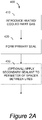
- FIG. 2A is a flowchart illustrating an example of a method of fabricating a pressure compensated IGU, 400, according to embodiments not forming part of the invention but representing background art that is useful for understanding the invention.
- the method 400 introduces a heated or cooled inert gas into a space between a (registered) first lite and a second lite and a spacer used to form the IGU (step 410 ).
- inert gases include argon, xenon, krypton, or a mixture thereof.
- Argon is typically used, but xenon and krypton have higher insulative properties; and, due to the higher price of the latter two, mixtures are sometimes used.
- the gas temperature sealed into the IGU may be between about -50°C to about +150°C.
- the inert gas has a temperature of between 30°C and about 150°C.
- the method also comprises forming a primary seal and thus the IGU (step 420 ).
- Step 420 is an example of a gas fill operation where the interior volume of the IGU is established (primary seal formed) with a heated or cooled inert gas therein. No further fill operation is necessary, and such methods can use standard IGU components, e.g. spacers and sealants.
- method 400 may also comprise applying a secondary sealant to a perimeter of the spacer between the first and second lites (step 430 ).
- the method 400 further comprises allowing the IGU to come to the ambient temperature at the manufacturing site after step 420 or after step 430.
- the IGU fabrication methods involve using an IGU press to press together IGU components (e.g., lites, adhesive and spacer) during one or more operations.
- the IGU press may be located in a chamber to provide a controlled environment or the IGU press itself may provide a controlled environment during the operation(s).
- the IGU press may be located within an oven chamber or refrigerated chamber during one or more operations to control the temperature of the IGU, the chamber having an inert gas environment.
- the chamber may be a conventional IGU press oven configured with inert gas atmosphere such that the IGU is pressed in a heated inert gas atmosphere.
- IGU formation is performed in a chamber configured with a cooled inert gas atmosphere.
- the chamber is configured to supply the inert gas atmosphere in a substantially moisture-free form.
- heated or cooled inert gas is introduced only to some areas of the IGU press, rather than the entire IGU press, prior to IGU formation.
- an inert gas is flushed through the registered IGU components in the IGU press during formation of the primary seal to form the IGU. A specific example of one such embodiment is described in more detail in the Example section below.
- the inert gas may be supplied in a substantially moisture-free form.
- an IGU, or its components are heated or cooled before the inert gas is introduced into the IGU (either after the IGU is formed or during primary seal formation).
- the inert gas is introduced into a hot IGU having one or more vent ports in the spacer. The one or more vent ports are sealed while the IGU components are still above ambient temperature.
- an IGU having one or more spacer vent ports is cooled. Inert gas is then introduced into the cooled IGU and the IGU sealed while still cool, thus trapping cooled inert gas in the IGU.
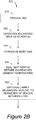
- FIG. 2B is a flowchart illustrating an example of a method of fabricating a pressure compensated IGU, 500 , according to embodiments forming part of the present invention.
- the IGU is heated or cooled before the inert gas is introduced into the IGU.
- method 500 includes providing an IGU having a first lite, a second lite, and a spacer between the first and second lites (step 510 ).
- Method 500 also includes heating or cooling the IGU having one or more open vent ports in the spacer (step 520 ).
- Method 500 includes introducing an inert gas into the interior volume of the IGU (step 530 ).
- the inert gas may be argon, xenon, krypton, or a mixture thereof.
- method 500 may also include applying a secondary sealant to a perimeter of the spacer between the first and second lites (step 550 ).
- sealed IGUs e.g. at ambient temperature or not, have inert gas removed from them, or introduced into them (at ambient temperature or not), via penetration of a seal and then resealing the seal. That is, these embodiments may include addition or removal of inert gas at ambient temperature of the IGU and the gas, or, the IGU and/or the gas may be at other than ambient temperature (e.g. between about -50°C and about +150°C). In this way, for example, the volume exchanged during the introduction or removal of inert gas may be lessened relative to not using heated or cooled gas and/or IGU.
- inert gas of a particular temperature may be added to obtain a final pressure level within the IGU.
- a smaller volume of hotter gas may be introduced to achieve the same end.
- the seal may be part of, or otherwise integrated with, the spacer.
- the spacer may be configured with a seal in the form of a sealable septum.
- the sealable septum is self-sealing, e.g. made of a polymeric material that allows penetration of a needle to transfer gas in or out of the interior volume, but which seals upon removal of the needle.
- the sealable septum includes a heat sealing polymer and resealing the IGU includes applying heat to the area of the sealing septum penetrated during introduction or removal of inert gas.
- the instrument e.g.
- a needle, used to transfer the gas may be heated or heatable, so that it locally melts the seal's material during penetration thereof, and thus allows the seal material to flow locally and reseal upon removal of the needle.
- a syringe pump is used to introduce or remove inert gas, e.g., via a needle that pierces the sealable septum or other seal.
- Use of a syringe pump allows for precise volumes to be introduced or removed from the IGU (in embodiments where heated or cooled gas is introduced while making the primary seal, e.g. in an IGU press, the (entire) interior volume of the IGU is established simultaneously with introduction of the heated or cooled gas).
- FIG. 2C is a flowchart illustrating an example of a method of fabricating a pressure compensated IGU, 600 , according to embodiments forming part of the invention.
- an inert gas e.g., argon, xenon, krypton, or a mixture thereof
- the inert gas may be substantially moisture free.
- method 600 includes introducing an inert gas into or removing inert gas from the interior space in an IGU by penetrating a seal of the IGU.
- a syringe pump can be used to penetrate the seal of the IGU and remove/introduce inert gas from/to the IGU.
- the inert gas may be heated or cooled, see 620 .
- the IGU is heated or cooled, see 630 , during transfer of the inert gas into or out of the interior volume.
- the method 600 reseals the IGU.
- the spacer of the IGU has a sealable septum through which the inert gas is removed or introduced.
- the sealable septum comprises a heat sealing polymer.
- resealing the IGU can include heating the area of the sealing septum around which was penetrated during introduction or removal of the inert gas.
- method 600 may include repeating steps 610-640 , e.g. if preformed pressure compensated IGUs are used to create pressure compensated IGUs having a different pressure within the interior volume. For example, a particular customer reports the elevation of his installation site incorrectly to the manufacturer. The pressure compensated IGUs are fabricated for this elevation. The correct elevation is revealed. The pressure compensated IGUs are recalibrated to the correct interior volume pressure. Re-sealable IGUs have the advantage of allowing such operations.
- the methods of fabricating pressure compensated IGUs can include one or more operations of the IGU fabrication processes described in reference to Figures 1A- 1B.
- the methods described with reference to Figures 2A-2C can include one or more operations of forming IGUs as described with reference to Figures 1A-1B .
- Table 1 is an example of a chart indicating the desired fill temperatures of inert gas (e.g., argon) needed to be sealed in an IGU in order to create a pressure compensated IGU for particular altitudes at the installation site, according to embodiments.
- inert gas e.g., argon
- the IGUs may be fabricated by methods herein where the IGU is sealed with inert gas of the particular temperature therein. These calculations are for Argon, but similar calculations for other inert gases and mixtures of inert gases can be determined by ordinary artisans.
- convex or concave of the installed IGU can be substantially avoided - and inert gas (leakage) loss can also substantially avoided while obviating the need for capillary or breather tubes for pressure equalization.
- These temperatures listed in Table 1 assume that the IGU fabrication takes place at approximately 500 feet above sea level, thus only ambient or heated gas is described, not cooled gas. Ordinary artisans could also calculate similar temperature values for cooled gases, used to make positive pressure IGUs at high elevation for installation at lower elevation.
- FIG. 3 depicts a schematic drawing of exemplary apparatus for fabricating pressure compensated IGUs, 700 .
- the apparatus 700 includes an IGU press, 720 , fitted with an inline gas heater, 730 (e.g., the commercially available heater from Imtec Acculine, LLC. of Fremont, California) that delivers heated gas (e.g., argon) into a four-way gas delivery manifold, 740 .
- the IGU press 720 includes three gas filling ports, 750 . Depending upon the size of the IGU, between one and three of gas filling ports 750 are used for gas fill of IGUs during operation.
- a four-way gas manifold 740 is fitted to the system apparatus 700 , whereby three of the manifold ports are plumbed to deliver gas to the three gas filling ports 750 of IGU press 720 .
- the final (fourth) manifold port of four-way manifold 740 is used for a bypass valve, 760 , (e.g. fitted with a solenoid activated valve) to release pressure if necessary or allow gas to flow out of the system while coming up to the desired temperature.
- Inline gas heater 730 feeds into the four-way manifold 740 .
- thermocouples, 770 for measuring the gas temperature within the gas lines, e.g., just after the inline gas heater 730 , just after exiting the four-way manifold 740 and just before the filling ports 750 of IGU press 720 (the heater also has internal thermocouples).
- Inline gas heater 730 receives gas from the gas source 780 .
- bypass valve 760 is open and the heated gas is allowed to pass through the four-way manifold 740 , not to the IGU press filling ports 750 , and out the open bypass valve 760 .
- bypass valve 760 is closed, and the heated gas flows to one or more filling ports 750 of the IGU press 720 (gas filling ports have internal valves as well, so that one, two or three can be used).
- Apparatus 700 is configured to deliver gas at temperatures between about 25°C and about 260°C. In a typical gas fill operation, gas used to make IGUs is at a temperature between about 90°C and about 150°C. A number of 14" by 14" IGUs were successfully fabricated using heated argon using apparatus 700 as illustrated in Figure 3 . IGUs were fabricated using 90°C, 120°C and 150°C argon and submitted for durability testing.
Landscapes
- Engineering & Computer Science (AREA)
- Civil Engineering (AREA)
- Structural Engineering (AREA)
- Electrochromic Elements, Electrophoresis, Or Variable Reflection Or Absorption Elements (AREA)
- Joining Of Glass To Other Materials (AREA)
Claims (7)
- Un procédé de fabrication d'un vitrage isolé compensé en pression (225), le procédé comprenant :a) la fourniture d'un vitrage isolé ventilé (225) comportant une première vitre (205), une seconde vitre (215) et une entretoise (220) entre les première et seconde vitres, dans lequel un revêtement électrochromique du dispositif (275) est disposé sur une surface d'au moins une des vitres, l'entretoise comprenant un ou plusieurs orifices d'évent ouverts ;b) le chauffage ou le refroidissement du vitrage isolé ventilé (225) ;c) l'introduction d'un gaz inerte dans le volume intérieur (255) du vitrage isolé ventilé chauffé ou refroidi par l'intermédiaire du ou des orifices d'évent ; etd) après l'introduction du gaz inerte en c), le scellement du ou des orifices d'évent ouverts avant que le vitrage isolé arrive à température ambiante.
- Le procédé selon la revendication 1, dans lequel le gaz inerte est de l'argon, du xénon, du krypton ou un mélange de ceux-ci et/ou dans lequel le gaz inerte est pratiquement exempt d'humidité.
- Le procédé de la revendication 2, comprenant en outre l'application d'un produit de scellement secondaire (260) sur le périmètre du vitrage isolé.
- Un procédé de fabrication d'un vitrage isolé compensé en pression (225), le procédé comprenant :a) la fourniture d'un vitrage isolé (225) comportant une première vitre (205), une seconde vitre (215) et une entretoise (220) entre les première et seconde vitres, dans lequel un revêtement électrochromique du dispositif (275) est disposé sur une surface d'au moins une des vitres ;b) l'introduction ou le retrait d'un gaz inerte dans ou à partir du volume intérieur (255) du vitrage isolé, par la pénétration d'un joint dans l'entretoise (220) du vitrage isolé, dans lequel le vitrage isolé est chauffé ou refroidi pendant que le gaz inerte est introduit ou retiré ;c) le rescellement du vitrage isolé.
- Le procédé selon la revendication 4, dans lequel le joint de l'entretoise (220) du vitrage isolé (225) est une cloison qui peut être scellée par laquelle le gaz inerte est retiré ou introduit, dans lequel éventuellement la cloison qui peut être scellée se compose d'un polymère de scellement thermique et c) comprend l'application de chaleur à la région de la cloison étant scellée et pénétrée pendant b).
- Le procédé selon la revendication 5, dans lequel une pompe à seringue est utilisée pendant b).
- Le procédé selon la revendication 4, dans lequel le gaz inerte est de l'argon, du xénon, du krypton ou un mélange de ceux-ci, et/ou dans lequel le gaz inerte est pratiquement exempt d'humidité.
Applications Claiming Priority (2)
| Application Number | Priority Date | Filing Date | Title |
|---|---|---|---|
| US201361810994P | 2013-04-11 | 2013-04-11 | |
| PCT/US2014/033870 WO2014169253A1 (fr) | 2013-04-11 | 2014-04-11 | Vitrages isolés compensés en pression |
Publications (3)
| Publication Number | Publication Date |
|---|---|
| EP2984052A1 EP2984052A1 (fr) | 2016-02-17 |
| EP2984052A4 EP2984052A4 (fr) | 2016-11-09 |
| EP2984052B1 true EP2984052B1 (fr) | 2018-12-26 |
Family
ID=51690048
Family Applications (1)
| Application Number | Title | Priority Date | Filing Date |
|---|---|---|---|
| EP14782906.3A Not-in-force EP2984052B1 (fr) | 2013-04-11 | 2014-04-11 | Procédés de fabrication d'un vitrage isolé compensé en pression |
Country Status (4)
| Country | Link |
|---|---|
| US (2) | US20160089869A1 (fr) |
| EP (1) | EP2984052B1 (fr) |
| CA (1) | CA2909224A1 (fr) |
| WO (1) | WO2014169253A1 (fr) |
Families Citing this family (21)
| Publication number | Priority date | Publication date | Assignee | Title |
|---|---|---|---|---|
| US10303035B2 (en) | 2009-12-22 | 2019-05-28 | View, Inc. | Self-contained EC IGU |
| US11314139B2 (en) | 2009-12-22 | 2022-04-26 | View, Inc. | Self-contained EC IGU |
| US9958750B2 (en) | 2010-11-08 | 2018-05-01 | View, Inc. | Electrochromic window fabrication methods |
| US8643933B2 (en) | 2011-12-14 | 2014-02-04 | View, Inc. | Connectors for smart windows |
| US9442339B2 (en) | 2010-12-08 | 2016-09-13 | View, Inc. | Spacers and connectors for insulated glass units |
| CN112731720A (zh) | 2010-12-08 | 2021-04-30 | 唯景公司 | 绝缘玻璃装置的改良隔板 |
| US10180606B2 (en) | 2010-12-08 | 2019-01-15 | View, Inc. | Connectors for smart windows |
| US10175549B2 (en) | 2011-03-16 | 2019-01-08 | View, Inc. | Connectors for smart windows |
| US9454055B2 (en) | 2011-03-16 | 2016-09-27 | View, Inc. | Multipurpose controller for multistate windows |
| US11719039B2 (en) | 2011-12-14 | 2023-08-08 | View, Inc. | Connectors for smart windows |
| US11255120B2 (en) | 2012-05-25 | 2022-02-22 | View, Inc. | Tester and electrical connectors for insulated glass units |
| EP2888427B1 (fr) | 2012-08-23 | 2021-02-17 | View, Inc. | Dispositifs électrochromiques (ec) alimentés par une énergie photonique |
| CA2850875A1 (fr) * | 2013-05-30 | 2014-11-30 | Benjamin J. Zurn | Vitrage isolant rempli de gaz adsorbable |
| CN105373459A (zh) * | 2014-08-15 | 2016-03-02 | 新益先创科技股份有限公司 | 控制装置 |
| US20170364201A1 (en) * | 2014-08-15 | 2017-12-21 | Touchplus Information Corp. | Touch-sensitive remote control |
| WO2016100075A1 (fr) | 2014-12-15 | 2016-06-23 | View, Inc. | Joints pour fenêtres électrochromiques |
| EP3070254A1 (fr) * | 2015-03-20 | 2016-09-21 | Sunglass Design Sarl | Vitrage isolant a pression interne adaptee lors du scellement |
| US10968685B2 (en) | 2016-01-04 | 2021-04-06 | PDS IG Holding LLC | Gas filling of an insulating glass unit |
| US11187028B2 (en) | 2017-07-01 | 2021-11-30 | PDSD IG Holding LLC | Filling and sealing device and method for an insulated glass unit |
| PL3477035T3 (pl) * | 2017-10-30 | 2020-12-28 | Technoform Glass Insulation Holding Gmbh | Element dystansowy do zastosowań fotowoltaicznych |
| KR102068648B1 (ko) * | 2017-11-30 | 2020-01-22 | 엘지전자 주식회사 | 진공유리 및 그 제조방법 |
Citations (1)
| Publication number | Priority date | Publication date | Assignee | Title |
|---|---|---|---|---|
| US20120147449A1 (en) * | 2010-12-08 | 2012-06-14 | Soladigm, Inc. | Spacers for insulated glass units |
Family Cites Families (10)
| Publication number | Priority date | Publication date | Assignee | Title |
|---|---|---|---|---|
| CH525376A (de) * | 1970-06-22 | 1972-07-15 | Meierhans Robert | Verfahren zur Herstellung von Doppelglasscheiben |
| US4393105A (en) * | 1981-04-20 | 1983-07-12 | Spire Corporation | Method of fabricating a thermal pane window and product |
| AT394997B (de) * | 1988-06-20 | 1992-08-10 | Glastechnische Ind Peter Lisec | Verfahren zum einstellen des bei normaltemperatur im innenraum einer isolierglasscheibe herrschendendruckes |
| US4941302A (en) * | 1989-06-09 | 1990-07-17 | Libbey-Owens-Ford Co. | Insulating double glazed window assembly |
| US5313761A (en) * | 1992-01-29 | 1994-05-24 | Glass Equipment Development, Inc. | Insulating glass unit |
| DE19611245A1 (de) * | 1996-03-22 | 1997-09-25 | Henkel Teroson Gmbh | Verwendung kontrolliert konditionierter Gase zur Füllung von Mehrscheibenisolierglas |
| US5948195A (en) * | 1997-03-11 | 1999-09-07 | Artic Window, Inc. | Process for rapid manufacturing multi-pane glass windows |
| US6068720A (en) * | 1998-07-01 | 2000-05-30 | Edge Seal Technologies, Inc. | Method of manufacturing insulating glass units |
| US6407847B1 (en) * | 2000-07-25 | 2002-06-18 | Gentex Corporation | Electrochromic medium having a color stability |
| JP5237054B2 (ja) * | 2008-11-07 | 2013-07-17 | 三菱重工業株式会社 | 蓄圧式燃料噴射装置の制御弁構造 |
-
2014
- 2014-04-11 EP EP14782906.3A patent/EP2984052B1/fr not_active Not-in-force
- 2014-04-11 CA CA2909224A patent/CA2909224A1/fr not_active Abandoned
- 2014-04-11 WO PCT/US2014/033870 patent/WO2014169253A1/fr not_active Ceased
- 2014-04-11 US US14/782,772 patent/US20160089869A1/en not_active Abandoned
-
2019
- 2019-03-20 US US16/359,945 patent/US20190210346A1/en not_active Abandoned
Patent Citations (1)
| Publication number | Priority date | Publication date | Assignee | Title |
|---|---|---|---|---|
| US20120147449A1 (en) * | 2010-12-08 | 2012-06-14 | Soladigm, Inc. | Spacers for insulated glass units |
Also Published As
| Publication number | Publication date |
|---|---|
| EP2984052A1 (fr) | 2016-02-17 |
| US20190210346A1 (en) | 2019-07-11 |
| US20160089869A1 (en) | 2016-03-31 |
| WO2014169253A1 (fr) | 2014-10-16 |
| EP2984052A4 (fr) | 2016-11-09 |
| CA2909224A1 (fr) | 2014-10-16 |
Similar Documents
| Publication | Publication Date | Title |
|---|---|---|
| EP2984052B1 (fr) | Procédés de fabrication d'un vitrage isolé compensé en pression | |
| KR101616835B1 (ko) | 라미네이트된 전기적으로 염색가능한 윈도우들 | |
| JP7574353B2 (ja) | 反りの少ない調光可能な窓ガラスおよびそれを含む断熱ガラスユニット | |
| US10435938B2 (en) | Vacuum insulated glass (VIG) window unit with reduced seal height variation and method for making same | |
| TWI582508B (zh) | 多窗格之電致變色窗戶 | |
| CN102388341B (zh) | 低缺陷率电致变色装置的制造 | |
| US20160136930A1 (en) | Electrochromic Devices and Manufacturing Methods Therefore | |
| CN102438827B (zh) | 层叠窗玻璃 | |
| CA2966027C (fr) | Feuille permettant d'economiser l'energie et son procede de fabrication | |
| US12098587B2 (en) | Glass panel unit and glass window | |
| CN116953971A (zh) | 调光玻璃及其制备方法 | |
| US12590490B2 (en) | Vacuum insulated glass and method of making same | |
| US20250028214A1 (en) | Electrochromic vacuum insulating glass units | |
| US20200263484A1 (en) | Vacuum insulated glass unit with a polymer spacer matrix and methods of making the same | |
| GB2580172A (en) | Vacuum insulated glazing unit |
Legal Events
| Date | Code | Title | Description |
|---|---|---|---|
| PUAI | Public reference made under article 153(3) epc to a published international application that has entered the european phase |
Free format text: ORIGINAL CODE: 0009012 |
|
| 17P | Request for examination filed |
Effective date: 20151022 |
|
| AK | Designated contracting states |
Kind code of ref document: A1 Designated state(s): AL AT BE BG CH CY CZ DE DK EE ES FI FR GB GR HR HU IE IS IT LI LT LU LV MC MK MT NL NO PL PT RO RS SE SI SK SM TR |
|
| AX | Request for extension of the european patent |
Extension state: BA ME |
|
| DAX | Request for extension of the european patent (deleted) | ||
| A4 | Supplementary search report drawn up and despatched |
Effective date: 20161011 |
|
| RIC1 | Information provided on ipc code assigned before grant |
Ipc: E06B 3/673 20060101ALI20161005BHEP Ipc: B32B 37/18 20060101ALI20161005BHEP Ipc: E06B 3/677 20060101ALI20161005BHEP Ipc: E06B 9/24 20060101ALI20161005BHEP Ipc: B32B 37/08 20060101ALI20161005BHEP Ipc: E06B 3/67 20060101ALI20161005BHEP Ipc: C03C 27/12 20060101AFI20161005BHEP Ipc: B32B 37/06 20060101ALI20161005BHEP Ipc: E06B 3/663 20060101ALI20161005BHEP |
|
| STAA | Information on the status of an ep patent application or granted ep patent |
Free format text: STATUS: EXAMINATION IS IN PROGRESS |
|
| 17Q | First examination report despatched |
Effective date: 20170609 |
|
| GRAP | Despatch of communication of intention to grant a patent |
Free format text: ORIGINAL CODE: EPIDOSNIGR1 |
|
| STAA | Information on the status of an ep patent application or granted ep patent |
Free format text: STATUS: GRANT OF PATENT IS INTENDED |
|
| INTG | Intention to grant announced |
Effective date: 20180621 |
|
| GRAS | Grant fee paid |
Free format text: ORIGINAL CODE: EPIDOSNIGR3 |
|
| GRAJ | Information related to disapproval of communication of intention to grant by the applicant or resumption of examination proceedings by the epo deleted |
Free format text: ORIGINAL CODE: EPIDOSDIGR1 |
|
| GRAL | Information related to payment of fee for publishing/printing deleted |
Free format text: ORIGINAL CODE: EPIDOSDIGR3 |
|
| GRAR | Information related to intention to grant a patent recorded |
Free format text: ORIGINAL CODE: EPIDOSNIGR71 |
|
| GRAA | (expected) grant |
Free format text: ORIGINAL CODE: 0009210 |
|
| STAA | Information on the status of an ep patent application or granted ep patent |
Free format text: STATUS: THE PATENT HAS BEEN GRANTED |
|
| INTG | Intention to grant announced |
Effective date: 20181114 |
|
| AK | Designated contracting states |
Kind code of ref document: B1 Designated state(s): AL AT BE BG CH CY CZ DE DK EE ES FI FR GB GR HR HU IE IS IT LI LT LU LV MC MK MT NL NO PL PT RO RS SE SI SK SM TR |
|
| REG | Reference to a national code |
Ref country code: GB Ref legal event code: FG4D |
|
| REG | Reference to a national code |
Ref country code: CH Ref legal event code: EP |
|
| REG | Reference to a national code |
Ref country code: AT Ref legal event code: REF Ref document number: 1081162 Country of ref document: AT Kind code of ref document: T Effective date: 20190115 |
|
| REG | Reference to a national code |
Ref country code: DE Ref legal event code: R096 Ref document number: 602014038709 Country of ref document: DE |
|
| REG | Reference to a national code |
Ref country code: IE Ref legal event code: FG4D |
|
| PG25 | Lapsed in a contracting state [announced via postgrant information from national office to epo] |
Ref country code: LT Free format text: LAPSE BECAUSE OF FAILURE TO SUBMIT A TRANSLATION OF THE DESCRIPTION OR TO PAY THE FEE WITHIN THE PRESCRIBED TIME-LIMIT Effective date: 20181226 Ref country code: HR Free format text: LAPSE BECAUSE OF FAILURE TO SUBMIT A TRANSLATION OF THE DESCRIPTION OR TO PAY THE FEE WITHIN THE PRESCRIBED TIME-LIMIT Effective date: 20181226 Ref country code: NO Free format text: LAPSE BECAUSE OF FAILURE TO SUBMIT A TRANSLATION OF THE DESCRIPTION OR TO PAY THE FEE WITHIN THE PRESCRIBED TIME-LIMIT Effective date: 20190326 Ref country code: FI Free format text: LAPSE BECAUSE OF FAILURE TO SUBMIT A TRANSLATION OF THE DESCRIPTION OR TO PAY THE FEE WITHIN THE PRESCRIBED TIME-LIMIT Effective date: 20181226 Ref country code: LV Free format text: LAPSE BECAUSE OF FAILURE TO SUBMIT A TRANSLATION OF THE DESCRIPTION OR TO PAY THE FEE WITHIN THE PRESCRIBED TIME-LIMIT Effective date: 20181226 Ref country code: BG Free format text: LAPSE BECAUSE OF FAILURE TO SUBMIT A TRANSLATION OF THE DESCRIPTION OR TO PAY THE FEE WITHIN THE PRESCRIBED TIME-LIMIT Effective date: 20190326 |
|
| REG | Reference to a national code |
Ref country code: NL Ref legal event code: MP Effective date: 20181226 |
|
| REG | Reference to a national code |
Ref country code: LT Ref legal event code: MG4D |
|
| PG25 | Lapsed in a contracting state [announced via postgrant information from national office to epo] |
Ref country code: SE Free format text: LAPSE BECAUSE OF FAILURE TO SUBMIT A TRANSLATION OF THE DESCRIPTION OR TO PAY THE FEE WITHIN THE PRESCRIBED TIME-LIMIT Effective date: 20181226 Ref country code: AL Free format text: LAPSE BECAUSE OF FAILURE TO SUBMIT A TRANSLATION OF THE DESCRIPTION OR TO PAY THE FEE WITHIN THE PRESCRIBED TIME-LIMIT Effective date: 20181226 Ref country code: RS Free format text: LAPSE BECAUSE OF FAILURE TO SUBMIT A TRANSLATION OF THE DESCRIPTION OR TO PAY THE FEE WITHIN THE PRESCRIBED TIME-LIMIT Effective date: 20181226 Ref country code: GR Free format text: LAPSE BECAUSE OF FAILURE TO SUBMIT A TRANSLATION OF THE DESCRIPTION OR TO PAY THE FEE WITHIN THE PRESCRIBED TIME-LIMIT Effective date: 20190327 |
|
| REG | Reference to a national code |
Ref country code: AT Ref legal event code: MK05 Ref document number: 1081162 Country of ref document: AT Kind code of ref document: T Effective date: 20181226 |
|
| PG25 | Lapsed in a contracting state [announced via postgrant information from national office to epo] |
Ref country code: NL Free format text: LAPSE BECAUSE OF FAILURE TO SUBMIT A TRANSLATION OF THE DESCRIPTION OR TO PAY THE FEE WITHIN THE PRESCRIBED TIME-LIMIT Effective date: 20181226 |
|
| PG25 | Lapsed in a contracting state [announced via postgrant information from national office to epo] |
Ref country code: ES Free format text: LAPSE BECAUSE OF FAILURE TO SUBMIT A TRANSLATION OF THE DESCRIPTION OR TO PAY THE FEE WITHIN THE PRESCRIBED TIME-LIMIT Effective date: 20181226 Ref country code: PL Free format text: LAPSE BECAUSE OF FAILURE TO SUBMIT A TRANSLATION OF THE DESCRIPTION OR TO PAY THE FEE WITHIN THE PRESCRIBED TIME-LIMIT Effective date: 20181226 Ref country code: PT Free format text: LAPSE BECAUSE OF FAILURE TO SUBMIT A TRANSLATION OF THE DESCRIPTION OR TO PAY THE FEE WITHIN THE PRESCRIBED TIME-LIMIT Effective date: 20190426 Ref country code: CZ Free format text: LAPSE BECAUSE OF FAILURE TO SUBMIT A TRANSLATION OF THE DESCRIPTION OR TO PAY THE FEE WITHIN THE PRESCRIBED TIME-LIMIT Effective date: 20181226 Ref country code: IT Free format text: LAPSE BECAUSE OF FAILURE TO SUBMIT A TRANSLATION OF THE DESCRIPTION OR TO PAY THE FEE WITHIN THE PRESCRIBED TIME-LIMIT Effective date: 20181226 |
|
| PG25 | Lapsed in a contracting state [announced via postgrant information from national office to epo] |
Ref country code: RO Free format text: LAPSE BECAUSE OF FAILURE TO SUBMIT A TRANSLATION OF THE DESCRIPTION OR TO PAY THE FEE WITHIN THE PRESCRIBED TIME-LIMIT Effective date: 20181226 Ref country code: EE Free format text: LAPSE BECAUSE OF FAILURE TO SUBMIT A TRANSLATION OF THE DESCRIPTION OR TO PAY THE FEE WITHIN THE PRESCRIBED TIME-LIMIT Effective date: 20181226 Ref country code: SM Free format text: LAPSE BECAUSE OF FAILURE TO SUBMIT A TRANSLATION OF THE DESCRIPTION OR TO PAY THE FEE WITHIN THE PRESCRIBED TIME-LIMIT Effective date: 20181226 Ref country code: IS Free format text: LAPSE BECAUSE OF FAILURE TO SUBMIT A TRANSLATION OF THE DESCRIPTION OR TO PAY THE FEE WITHIN THE PRESCRIBED TIME-LIMIT Effective date: 20190426 Ref country code: SK Free format text: LAPSE BECAUSE OF FAILURE TO SUBMIT A TRANSLATION OF THE DESCRIPTION OR TO PAY THE FEE WITHIN THE PRESCRIBED TIME-LIMIT Effective date: 20181226 |
|
| REG | Reference to a national code |
Ref country code: DE Ref legal event code: R097 Ref document number: 602014038709 Country of ref document: DE |
|
| PG25 | Lapsed in a contracting state [announced via postgrant information from national office to epo] |
Ref country code: AT Free format text: LAPSE BECAUSE OF FAILURE TO SUBMIT A TRANSLATION OF THE DESCRIPTION OR TO PAY THE FEE WITHIN THE PRESCRIBED TIME-LIMIT Effective date: 20181226 Ref country code: DK Free format text: LAPSE BECAUSE OF FAILURE TO SUBMIT A TRANSLATION OF THE DESCRIPTION OR TO PAY THE FEE WITHIN THE PRESCRIBED TIME-LIMIT Effective date: 20181226 |
|
| PLBE | No opposition filed within time limit |
Free format text: ORIGINAL CODE: 0009261 |
|
| STAA | Information on the status of an ep patent application or granted ep patent |
Free format text: STATUS: NO OPPOSITION FILED WITHIN TIME LIMIT |
|
| REG | Reference to a national code |
Ref country code: CH Ref legal event code: PL |
|
| 26N | No opposition filed |
Effective date: 20190927 |
|
| REG | Reference to a national code |
Ref country code: BE Ref legal event code: MM Effective date: 20190430 |
|
| PG25 | Lapsed in a contracting state [announced via postgrant information from national office to epo] |
Ref country code: MC Free format text: LAPSE BECAUSE OF FAILURE TO SUBMIT A TRANSLATION OF THE DESCRIPTION OR TO PAY THE FEE WITHIN THE PRESCRIBED TIME-LIMIT Effective date: 20181226 Ref country code: LU Free format text: LAPSE BECAUSE OF NON-PAYMENT OF DUE FEES Effective date: 20190411 |
|
| PG25 | Lapsed in a contracting state [announced via postgrant information from national office to epo] |
Ref country code: CH Free format text: LAPSE BECAUSE OF NON-PAYMENT OF DUE FEES Effective date: 20190430 Ref country code: LI Free format text: LAPSE BECAUSE OF NON-PAYMENT OF DUE FEES Effective date: 20190430 |
|
| PG25 | Lapsed in a contracting state [announced via postgrant information from national office to epo] |
Ref country code: BE Free format text: LAPSE BECAUSE OF NON-PAYMENT OF DUE FEES Effective date: 20190430 Ref country code: SI Free format text: LAPSE BECAUSE OF FAILURE TO SUBMIT A TRANSLATION OF THE DESCRIPTION OR TO PAY THE FEE WITHIN THE PRESCRIBED TIME-LIMIT Effective date: 20181226 |
|
| PG25 | Lapsed in a contracting state [announced via postgrant information from national office to epo] |
Ref country code: TR Free format text: LAPSE BECAUSE OF FAILURE TO SUBMIT A TRANSLATION OF THE DESCRIPTION OR TO PAY THE FEE WITHIN THE PRESCRIBED TIME-LIMIT Effective date: 20181226 |
|
| PG25 | Lapsed in a contracting state [announced via postgrant information from national office to epo] |
Ref country code: IE Free format text: LAPSE BECAUSE OF NON-PAYMENT OF DUE FEES Effective date: 20190411 |
|
| REG | Reference to a national code |
Ref country code: DE Ref legal event code: R082 Ref document number: 602014038709 Country of ref document: DE Representative=s name: HL KEMPNER PATENTANWALT, RECHTSANWALT, SOLICIT, DE |
|
| PG25 | Lapsed in a contracting state [announced via postgrant information from national office to epo] |
Ref country code: CY Free format text: LAPSE BECAUSE OF FAILURE TO SUBMIT A TRANSLATION OF THE DESCRIPTION OR TO PAY THE FEE WITHIN THE PRESCRIBED TIME-LIMIT Effective date: 20181226 |
|
| PG25 | Lapsed in a contracting state [announced via postgrant information from national office to epo] |
Ref country code: HU Free format text: LAPSE BECAUSE OF FAILURE TO SUBMIT A TRANSLATION OF THE DESCRIPTION OR TO PAY THE FEE WITHIN THE PRESCRIBED TIME-LIMIT; INVALID AB INITIO Effective date: 20140411 Ref country code: MT Free format text: LAPSE BECAUSE OF FAILURE TO SUBMIT A TRANSLATION OF THE DESCRIPTION OR TO PAY THE FEE WITHIN THE PRESCRIBED TIME-LIMIT Effective date: 20181226 |
|
| PGFP | Annual fee paid to national office [announced via postgrant information from national office to epo] |
Ref country code: DE Payment date: 20210428 Year of fee payment: 8 Ref country code: FR Payment date: 20210426 Year of fee payment: 8 |
|
| PGFP | Annual fee paid to national office [announced via postgrant information from national office to epo] |
Ref country code: GB Payment date: 20210427 Year of fee payment: 8 |
|
| PG25 | Lapsed in a contracting state [announced via postgrant information from national office to epo] |
Ref country code: MK Free format text: LAPSE BECAUSE OF FAILURE TO SUBMIT A TRANSLATION OF THE DESCRIPTION OR TO PAY THE FEE WITHIN THE PRESCRIBED TIME-LIMIT Effective date: 20181226 |
|
| REG | Reference to a national code |
Ref country code: DE Ref legal event code: R119 Ref document number: 602014038709 Country of ref document: DE |
|
| GBPC | Gb: european patent ceased through non-payment of renewal fee |
Effective date: 20220411 |
|
| PG25 | Lapsed in a contracting state [announced via postgrant information from national office to epo] |
Ref country code: GB Free format text: LAPSE BECAUSE OF NON-PAYMENT OF DUE FEES Effective date: 20220411 Ref country code: FR Free format text: LAPSE BECAUSE OF NON-PAYMENT OF DUE FEES Effective date: 20220430 Ref country code: DE Free format text: LAPSE BECAUSE OF NON-PAYMENT OF DUE FEES Effective date: 20221103 |