EP2984251B1 - Lame de revêtement pour échafaudages - Google Patents
Lame de revêtement pour échafaudages Download PDFInfo
- Publication number
- EP2984251B1 EP2984251B1 EP14719671.1A EP14719671A EP2984251B1 EP 2984251 B1 EP2984251 B1 EP 2984251B1 EP 14719671 A EP14719671 A EP 14719671A EP 2984251 B1 EP2984251 B1 EP 2984251B1
- Authority
- EP
- European Patent Office
- Prior art keywords
- floorboard
- elements
- longitudinal beam
- projections
- engagement
- Prior art date
- Legal status (The legal status is an assumption and is not a legal conclusion. Google has not performed a legal analysis and makes no representation as to the accuracy of the status listed.)
- Active
Links
Images



Classifications
-
- E—FIXED CONSTRUCTIONS
- E04—BUILDING
- E04G—SCAFFOLDING; FORMS; SHUTTERING; BUILDING IMPLEMENTS OR AIDS, OR THEIR USE; HANDLING BUILDING MATERIALS ON THE SITE; REPAIRING, BREAKING-UP OR OTHER WORK ON EXISTING BUILDINGS
- E04G17/00—Connecting or other auxiliary members for forms, falsework structures, or shutterings
- E04G17/002—Workplatforms, railings; Arrangements for pouring concrete, attached to the form
-
- E—FIXED CONSTRUCTIONS
- E04—BUILDING
- E04G—SCAFFOLDING; FORMS; SHUTTERING; BUILDING IMPLEMENTS OR AIDS, OR THEIR USE; HANDLING BUILDING MATERIALS ON THE SITE; REPAIRING, BREAKING-UP OR OTHER WORK ON EXISTING BUILDINGS
- E04G1/00—Scaffolds primarily resting on the ground
- E04G1/15—Scaffolds primarily resting on the ground essentially comprising special means for supporting or forming platforms; Platforms
- E04G1/153—Platforms made of plastics, with or without reinforcement
-
- E—FIXED CONSTRUCTIONS
- E04—BUILDING
- E04G—SCAFFOLDING; FORMS; SHUTTERING; BUILDING IMPLEMENTS OR AIDS, OR THEIR USE; HANDLING BUILDING MATERIALS ON THE SITE; REPAIRING, BREAKING-UP OR OTHER WORK ON EXISTING BUILDINGS
- E04G5/00—Component parts or accessories for scaffolds
- E04G5/08—Scaffold boards or planks
Definitions
- a decking for scaffolds having the above features (a) to (d) is known from DE 10 2011 007 431 A1 known.
- Each adjacent elements are, at least in terms of forces acting at right angles to the element-Nutztime, thereby bi-directionally positively engaged with each other that extend inserted filler of foam plastic over the border between two adjacent elements away.
- a concreting panel which has two edge beams and a plurality of plastic or metal elements leading from edge beam to edge beam.
- the plastic elements have plastic stiffening ribs.
- the metal elements have side walls and snap bars, which lead obliquely from the formwork to the respective side wall and optimize the dissipation of forces into the edge beams.
- a scaffold is a device that allows people or loads to be located in a location that is remote from the location of the base of the scaffolding, with the weight of the person (s) and / or load ( en) is forwarded by means of the scaffold from the whereabouts to the location of the scaffold base.
- the abode referred to is at a higher level than the location of the scaffold base; however, the location may also be laterally spaced or at a lower level than the location of the scaffold base.
- the location of the scaffold base z. B. the ground or z. B. may be a building surface as the top of a floor ceiling.
- a scaffolding for constructing a concrete formwork for a bridge arch or for a tunnel ceiling as well as a scaffold for carrying out work on the inside of a church vault, and a scaffold for carrying out manufacturing work on the underside of the wing of a large aircraft.
- the framework is erected parallel to a building wall, so that one can carry out work on the building wall from the framework.
- the flooring plank according to the invention is also provided for a type of scaffold which is usually called a scaffold framework.
- Console scaffoldings have - usually in a number of arranged in a row - consoles, which are also commonly called scaffold consoles, which are attached to a console supporting structures and project from this.
- This structure may be, in particular, a building or a concreting formwork, in which case the area from which the brackets protrude is also substantially vertical, even in accordance with the invention.
- a particularly typical console scaffold, which is also preferred for the covering flooring according to the invention is a so-called working and concreting platform, in which on the outside of wall formwork elements Consoles are mounted in series, on which flooring planks are mounted.
- Inventive flooring planks are elements for attachment to scaffolds (in which context the word scaffold denotes the support structure of the scaffolding which is not yet complete).
- Floors are those elements of the complete scaffolding on which - depending on the scaffolding - people can stand or walk or other loads, such. As tools, mortar containers, bricks, can be parked. Siding boards are sometimes referred to as Gehbelag or Gehbelagdielen, which terminology comes from the fact that you can go on these elements - in contrast to the rest of the scaffold.
- the term plank flooring is preferred, to indicate that it can also be used in those cases where it is not important to walk on the plank flooring.
- the term lining plank has been chosen to express that it is usually an elongated structure, which is typically narrower than long. Overall, the structure is - roughly speaking - plate-like, d. H. It has a thickness that is significantly smaller than the length and width of the floorboard.
- the claim 1 is not limited to flooring planks, in which the longitudinal members are longer than the measured transverse to the longitudinal beams floorboard width.
- flooring planks for scaffolding which consist of metal.
- metallic decking can be lighter than decking boards and are much more durable than decking boards.
- the flooring plank according to the invention realizes a fundamentally different construction principle.
- the forces which occur in the region of a span (or respectively one of several spans) on the covering plank which lead to a bending stress of the planking, essentially taken up by the longitudinal members.
- the covering plank in a front view in which the elements mentioned in claim 1 each lead horizontally from the first side member to the second side member, the forces coming into this span on the respective element will lead to a bending stress of the element in question derived from the element in question to the two side members.
- the derived from the plastic elements loads are much lower than in the above-mentioned paragraph covering plank with a one piece for almost the entire plank length plastic part.
- outer side members as used in the application is not intended to be limiting in that these outer side members must necessarily be located entirely at the outer edge of the covering plank. It should only be expressed that these two outer side members are each nearer to the respective edge of the lining plank than at the center line of the planking. It is thus possible that the plastic elements in each case go beyond the two outer longitudinal members to the edge end of the covering plank. This too should with the expression “elements that each lead from the first side member to the second side member” include. In one embodiment of the invention, however, it is the case that the two outer longitudinal members are positioned completely against the relevant edge ends of the covering plank, that is to say that the elements do not extend beyond the longitudinal members to the outside.
- the floor covering according to the invention is not limited to the fact that only two side members, namely the "outer, spaced side members" cited in claim 1, are present.
- the distance between the two outer side members is relatively large or when particularly large loads are to be expected on the members, it is possible to provide one or more further side members between the "two outer, spaced side members".
- plastic element as used in the application does not necessarily mean that the element must be 100% plastic (including any reinforcing means, e.g., fibers, in the plastic), although this is a viable option. Other materials may be present in minor amounts, e.g. cast-in metal bushings for holding screws.
- the dimension of the elements as measured in the direction from the first outer side rail to the second outer side rail is dictated by the desired width of the decking.
- the dimension of the elements, measured in the direction of the longitudinal direction of the side members, can be determined according to manufacturing requirements for the element in question, and usually follows a suitable modularity to the frame.
- the dimension of the respective element, referred to second in this paragraph is at least 50% and at most 200% of the dimension mentioned first in this paragraph.
- the bidirectionally positive engagement between each two adjacent elements causes forces, the at least one component perpendicular to the respective element-Nutzseite have to be divided to divide the forces on several elements.
- the load-bearing capacity of each element is supported by the load-carrying capacity of at least one neighboring element or also several neighboring elements (at least one left then and at least one right subsequently, or also several consecutive rows to the left and / or several consecutive rows to the right).
- a load for. B. the foot of a person who comes directly to two adjacent elements.
- at least one further element adjoining this element pair is involved in the force derivation.
- respective bidirectional form-fitting engagement that no grading is formed at the transition between a directly loaded element and a not directly loaded element. This is also a safety-enhancing feature.
- a convenient way to create the bidirectional interlocking engagement between two adjacent elements is that one forms the respective element edges so that the two adjacent elements are moved towards each other, so as it can be put together. In this way, the assembly of the elements and thus the flooring plank designed particularly simple. Tensile forces in the longitudinal direction of the longitudinal members are not transferred at the relevant intervention site on schedule. Furthermore, it is possible-instead of or in addition-to design the bi-directional positive-locking element / element interventions in such a way that no pressure forces acting in the longitudinal direction of the side members are transmitted at the points of engagement, at least not before any further further collapsing movement takes place between adjacent elements Has. The formation of the element / element interventions can be designed such that forces which have at least one component in the direction of the extension direction of the respective element edge are respectively transmitted between the two adjacent elements.
- the first longitudinal carrier and the second longitudinal carrier as well as, at least predominantly Part of the elements, in each case the respective two opposite edges of the elements have such a shape that, at least in terms of forces acting at right angles to the element Nutztime, bidirectionally positive side member / element engagement. This training perfects the power transmission from the elements to the side members.
- the elements have at their respective edges such a plastic molding that by means of this plastic molding of the positive element / element engagement and / or the form-fitting Side member / element engagement is accomplished.
- These means may be formed integrally with the rest of the element.
- the flooring plank according to the invention which may also contain at least one of the possibility features disclosed in the preceding text, it is possible that those elements which have two element / element engagement edges, each formed with two mutually substantially rotationally symmetric element / element engagement edges are, wherein the axis of rotational symmetry passes through the center of the useful side of the element in question and is perpendicular to this Nutzseite. In this way, it is no longer necessary to pay attention to which of the two element / element engagement edges of the element in question is connected to a neighboring element when assembling the elements and thus the covering plank.
- the two possible relative orientations are equally "correct" and result in the interlocking element / element engagement.
- the flooring plank according to the invention which may also contain at least one of the possible features disclosed in the preceding text, that the respective form-fitting element / element engagement and / or the respective form-fitting side member / element engagement, at least in the respective predominant part the cases of positive engagement, is divided into a plurality of engagement points along the respective element edge.
- the elements each at the edge or edges where interlocking element / element engagement takes place, a number of projections and Have gaps between the projections, wherein this series of projections and gaps and a series of projections and gaps on the respective edge of a neighboring element mesh with each other, and wherein at least the majority of the projections of these two rows is formed either such that they rest from above on counter surfaces of the neighboring element, or is such that rest on them from above mating surfaces of the neighboring element.
- the covering floor according to the invention which may also contain at least one of the possible features disclosed in the preceding text, that the projections, at least for the most part, viewed in a section extending along the row of projections, each having a U-shaped configuration have opening of the U facing away from the useful side of the element.
- Such projections are favorable in terms of production.
- the required to overcome the shear stress material cross section can be displayed well.
- the elements may each have a series of spaced projections at the edges where form-fitting side member / element engagement takes place a groove of the respective longitudinal carrier engage, wherein preferably at least a portion of these projections a wall-like shape with a direction transverse to the longitudinal direction has the respective longitudinal beam aligned Wanderstreckungsebene.
- This training is particularly low production and allows easy representation of the required for the transmission of shear forces material cross sections.
- the elements are each releasably connected to the first side member and the second side member, preferably by means of screws and / or rivets. In this way, not only the assembly of the planking in the simplest way possible. Rather, even already used flooring planks can be easily disassembled (recycling!) And / or repaired. Conversion to shorter flooring planks and further use of elements in other flooring planks are readily possible.
- the elements are injection-molded parts.
- the elements whether injection molded or not, can have - in addition to the stiffening tubes on the back - stiffening ribs on the back and / or a slip-resistant uneven design on the useful side.
- the covering plank contains a plurality of elements, each element is considerably smaller than the plastic body of the above-mentioned, known plastic covering plank.
- the elements present in the covering flooring according to the invention can therefore be produced much less complicated and cheaper.
- the training as a plastic injection molded part allows production on injection molding machines with a common size of the production forms. Injection molding allows the molding of desired molded part details cost directly in the injection mold.
- stiffening tubes and / or the said stiffening ribs and / or said non-slip uneven design on the useful side can be molded in a simple manner during injection molding.
- the elements used in the covering flooring according to the invention can be made of fiber-reinforced plastic.
- the execution as an injection molded part is possible with fiber-reinforced plastic.
- connection carriers are present, which are connected to the first side member and the second side member, preferably releasably, and for a Attachment of the planking are formed on a scaffold.
- the at least two connection carriers are intended to dissipate the forces or loads, which are introduced via the elements, ultimately to the framework or the scaffold consoles in the state installed in the scaffold or in the condition of the screed brackets attached to the scaffold consoles ,
- the at least two connection carrier can be made of metal.
- the outer side members and the connection carrier may be made of metal.
- suitable metals for the two outer side members are aluminum and aluminum alloys, whereas for the connection supports, the best option is steel, since at times very high loads can add up. In both cases, these may be extruded, rolled or canted profiles.
- connection carrier is to be understood functionally broad.
- the relevant connection carrier can also be realized by a meaningful thick sheet metal or a folded sheet metal.
- the at least two connection carrier can be designed so that they allow the attachment of the covering plank to cantilever frame consoles.
- the at least two connection carriers can be provided on the underside of the covering plank.
- connection carrier which is formed for a Auflagerung of the relevant flooring planking on a transverse to the longitudinal direction of the covering plank extending scaffold support
- said connection support are preferably designed in such a way that can be stored on this framework carrier transverse ends of two flush-fitting flooring planks.
- the latter can be z. B. realize that each of the connection carrier has a number of spaced support claws, wherein the support claws of the connection carrier of the aligned subsequent flooring plank fit into the gaps between the support claws of the considered flooring plank.
- the flooring plank according to the invention which may also contain at least one of the possible features disclosed in the preceding text, it is possible that it is at least 0.5 m, preferably at least 1 m, long and at least 25 cm, preferably at least 32 cm wide , If very wide coverings are desired in a scaffold or a console scaffold, it is also possible to attach two or even more scouring boards according to the invention next to one another, so that their widths add up.
- Another object of the invention is a scaffold, characterized in that it contains several flooring planks of the disclosed in this application embodiment.
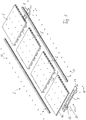
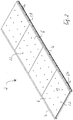
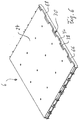
- Planking 2 shown has as main components: two edge support 4, four elements 6 and two connection carrier 8. Die Fig. 1 can also be viewed as a representation of these main components before assembling them.
- Each of the two side rails 4 in this embodiment has a cross-section like a double-T beam and, in this embodiment, is an extruded profile of aluminum or an aluminum alloy.
- the positioned at the two ends of the covering plank 2 elements 6 are formed equal to each other, but mounted in mirror image in the covering plank 2.
- the two positioned between the end elements 6 elements 6 are formed equal to each other. The difference between the end elements 6 and the remaining normal elements 6 will be described in more detail below.
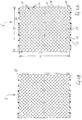
- the element 6 has the overall shape of a - in plan view of the useful side 10 or on the back 12 substantially rectangular - plate whose thickness is much smaller than the first dimension 14 and the second dimension 16 (s. Fig. 4A ) of the element 6.
- the second dimension 16 lies in a direction parallel to the longitudinal direction of the longitudinal members 4. In the illustrated embodiment, the second dimension 16 is about 90% of the size of the first dimension 14.
- the aspect ratio between the The second dimension 16 and the first dimension 14 may be varied quite freely within reasonable design constraints.
- FIGS. 4A and 4B the real appearance of the relevant element 6 in plan view of the Nutzseite 10 play.
- the elevations 18 are arranged overall in the form of straight, broken lines 20, each extending at 45 ° relative to the edges of the element.
- the surveys 18 create an overall uneven, anti-slip profiling of the useful side 10 of the relevant element. 6
- FIGS. 1 . 2 . 6 . 7 . 9 . 10 the elevations 18 are omitted for the sake of drawing simplification.
- FIGS. 1 . 2 . 4A, 4B . 5A, 5B . 6 . 7 . 9 it can be seen that, distributed in a checkerboard pattern on the useful side 10 of the relevant element 6-in this exemplary embodiment-there are 12 holes 22 which pass through the material of the element 6 from the useful side 10. These holes 22 serve the drainage. They are in Fig. 10 omitted only for the sake of drawing simplification.
- Each element 6 is a one-piece injection molded part.
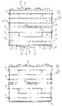
- each of the elements 6, which are not an end member one can constructively a Nutztime wall 24; 10 rear stiffening ribs 26 extending on the back side of the utility side wall 24 parallel to the first dimension 14; some short stiffening ribs 28 extending at the rear of the utility side wall 24 in the direction of the second dimension 16; two edge formations 30 of the first type, which are provided for bidirectionally positive element / element engagement; two edge formations 32 of the second type, which are provided for bidirectionally form-fitting side members / element engagement; and two boundary ribs 54 that extend along the edge formations 32 of the second type.
- Fig. 3 it can be seen that the stiffening ribs 26 in the vicinity of the longitudinal members 4 have a lower height (measured at right angles to the useful side 10) and that the rib height in a large central region is so great that the relevant element 6, taken as a whole, has substantially the same thickness as each of the side members 4 (see, in particular Fig. 3 ).
- the edge formation 30 of the first type includes four regular width projections b and a projection 36 of approximately half width b / 2, these projections 34 and 36 being lined up along the respective element edge at a mutual distance of width a.
- the gap width a is slightly larger than the projection width b, so that a projection 34 of an adjacent element 6 fits into each of the gaps 38, as can be seen in FIG Fig. 3 and in synopsis with Figs. 5A and 5B sees.
- Each of the projections 34, 36 has a top wall 40 which extends parallel to the payload side 10 of the element 6 (see FIG. Fig. 1 ), and at the back of the upper wall 40 a plurality of stiffening ribs 42.
- the upper wall 40 is located approximately at the level of half the thickness of the element. 6
- each of the gaps 38 there is a pocket 44, which occupies approximately the lower (of the Nutzseite 10 more distant) half of the thickness of the element 6.
- the respective pocket 44 is delimited by the lower edges of ribs 46 which extend downwards from the rear side of the useful side wall 24. Due to the described geometry of the projections 34, the gaps 38 and the pockets 44 adjacent elements 6 - with a relative direction of movement, which is in the same direction as the longitudinal extension of the side members 4 - moved towards each other and finally "put together". In this case, each projection 34 or 36 passes into a pocket 44. If now comes from the useful side 10 ago a load on a viewed element 6, z. B.
- the described takes place in the reverse manner, when a neighboring element of a considered element 6 is loaded.
- the neighboring element is supported by one or more projections 34 of the considered element 6 on the observed element 6. From the described and from the FIGS. 1 to 5B shows that you see nothing of the edge formations 30 of the first type in assembled decking 2.
- the positive, with respect to acting at right angles to the element-Nutzrest 10 bidirectionally effective teeth of the two edges 30 adjacent elements 6 takes place below the visible from above the useful side wall 24 from.
- the two edge formations 30 of the first type are rotationally symmetrical in the element 6, the axis of rotation passing through the center of the useful side 10 of the element 6 and being at right angles to this useful side 10.
- the position of the axis of rotation is in Fig. 5A marked with a small cross 48. This results in that upon rotation of the element 6 by 180 ° about the axis of rotation 48, the edge formation 30 of the first type, which is initially at in Fig. 5A left edge 30, in which one edge formation 30 merges, which one in Fig. 5A looks at the right edge of the drawing.
- the half-width projection 36 which is lower left at the left edge 30, comes to lie on the right edge 30 to the upper right.
- This rotationally symmetric configuration has the effect of being able to "infect" a contemplated element 6 on the side of a first-type edge 30 of a neighboring element 6, irrespective of which of the two first-type adjacent edges 30 is used therefor. One therefore does not have to pay attention to the mounting with which edge 30 of the first type one "infects" the neighboring element 6.
- FIG. 5B drawn end element 6 differs from that in Fig. 5A illustrated normal element 6 in that only one edge 30 of the first type with the projections 34, 36 and the gaps 38 and the pockets 44 is formed, as described, whereas the opposite edge 50 is simply formed as a rib extending from edge 32 of the second type extends to edge 32 of the second type. Because of the described rotational symmetry of the normal elements 6, the two end elements can be made the same. This in Fig. 5B drawn end element 6 can be rotated by 180 ° about the drawn axis 48 and then used at the other end of the covering plank 2 as the end element 6.
- edge formation 32 of the second type will now be described. This is always the same for all normal elements 6 and for the two end elements 6.
- Each edge formation 32 of the second type includes 10 protrusions 52 which are distributed over the length of the respective edge 32 at a mutual distance, wherein a part of the distances are equal to each other, but also partially smaller distances are present.
- Each projection 52 has substantially the shape of a wall whose plane is perpendicular to the useful side 10 and perpendicular to the longitudinal extent of the respective longitudinal member 4. The projections 52 sit in places where they each form an extension of a rib 26 of the element. At the roots of the projections 52 is a common boundary rib 54, which is aligned in the same direction as the edge 32.
- the projections 52 have such a course in each case of their edge that the projections 52 each in a groove or the U-shaped receiving space of a half of the double-T-profile of the respective longitudinal member 4 fit.
- Fig. 1 bottom left, you can see one of the twoeursen 8.
- Fig. 3 in that the terminating support 8 is screwed in each case from the rear side to the two longitudinal members 4 and to an end element 6 by means of screws 60.
- the two connection carrier 8 are formed equal to each other.
- connection carrier 8 is pressed from sheet steel and has in each case more to the terminal support end toward a section 62 with - roughly speaking - U-shaped cross-section.
- connection carrier 8 is provided at one of its two ends with a bolt 64 which extends in the direction of the longitudinal extension of the connection carrier 8 and - protrudes with assembled plank 2 - with a portion of its length beyond the local side member 4.
- Fig. 6 an end element 6 is shown with an alternative embodiment of the rim 30 of the first type.
- the projections 34 and the gaps 38 are no longer in a "lower floor", which is located a distance away from the Nutzseite 10, formed, but as edge profiling of Nutzhos-wall 24.
- the gaps 38 jump a bit further to the middle Uses Wall 24 area back as it the position of a limiting rib 66 corresponds, which runs there in the same direction as the edge 30.
- the projections 34 of the adjacent edge 30 of an adjacent element 6 can be placed on the exposed upper edge of the limiting rib 66. The same applies vice versa for the projections 34 of in Fig.
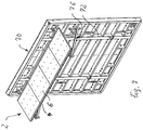
- FIGS. 7 . 8, 9 It is illustrated how to apply the covering plank 2 described with reference to FIGS. 1 to 5 to a wall formwork module of a concrete wall formwork.
- Drawn is a so-called frame formwork module 70, which consists essentially of a skeleton of metal beams 72 and two attached thereto form skin panels 74 on the useful side of the frame formwork module 70.
- At the support frame 72 are two spaced apart - roughly speaking - triangular scaffold brackets 76 attached.
- On the upper, horizontal arm 78 of each bracket 76 is one of the two connection carrier 8 of the covering plank 6 is placed.
- a partial length of the bolt 64 described above has been inserted into a matching bush-like channel on the respective console 76.
- connection carrier 8 is equipped with undercuts 80, in which transverse bolts are received, which are provided on the horizontal leg 78 of the bracket 76.
- undercuts 80 in which transverse bolts are received, which are provided on the horizontal leg 78 of the bracket 76.
- a connection carrier 84 are provided with two support brackets 82 instead of the connection carrier 8 at each end of the covering plank 2, wherein the connection carrier 84 are in turn attached to the two longitudinal members 4.
- Each of the two connection carrier 84 is made of strong, folded sheet metal, wherein it is possible to form the support claws 82 respectively from a notched sheet metal area.
- Fig. 10 are also all the details of the elements and the screws 58 are not shown, as they have already been described in connection with the preceding embodiments.
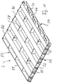
- Fig. 11 designated embodiment of the invention differs from the in Fig. 1 to 5B illustrated embodiments in that the element 6 on its back instead of the 10 stiffening ribs 26 which extend parallel to the edges 30, four stiffening tubes 86 and an end stiffening rib 88 has.
- the stiffening tubes 86 are each hollow and have a rectangular cross-section. In the case of the stiffening tubes 86, it could also be said that in each case two adjacent stiffening ribs are joined together by a rear wall extending parallel to the useful side 10. Alternatively, one could provide eight stiffening tubes 86 immediately adjacent to one another laterally so that the element 2 is almost completely closed at the rear. In both cases, the stiffening tubes 86 may have a different cross-section than the drawn rectangular cross-section, in particular an arcuate, wavy or zigzag-shaped extending rear wall as far away from its user side boundary.
- FIG. 11 drawn element 8 is an end element 6. If one imagines the projections 84, the gaps 38 and the pockets 44, which are seen in the edge formation 30 of the first type in the drawing right-bottom, also complements the opposite, parallel edge , one has in front of how a normal element 6 formed with stiffening tubes 86 looks like.
- Drawn element 6 is an injection molded part. This element 6 is more rigid than the elements 6 according to the Fig. 1 to 5B ,
Landscapes
- Engineering & Computer Science (AREA)
- Architecture (AREA)
- Mechanical Engineering (AREA)
- Civil Engineering (AREA)
- Structural Engineering (AREA)
- Floor Finish (AREA)
- Finishing Walls (AREA)
Claims (17)
- Plancher (2) pour échafaudages, comprenant :(a) deux poutres longitudinales (4) extérieures écartées l'une de l'autre, de préférences métalliques ;(b) plusieurs éléments (6) rectangulaires juxtaposés, en matière plastique et essentiellement en forme de plaque, chacun s'étendant de la première poutre longitudinale (4) à la seconde poutre longitudinale (4) ;(c) les éléments (6) étant respectivement connectés à la première poutre longitudinale (4) et à la seconde poutre longitudinale (4) ;(d) et les éléments (6) adjacents étant disposés en engagement positif bidirectionnel l'un avec l'autre, au moins en termes de forces s'exerçant à angle droit sur les côtés utiles (10) de l'élément,caractérisé en ce que les éléments (6) comportent des tubes de renfort (86) à l'arrière, leur cours longitudinal s'étendant en direction de la première poutre longitudinale (4) à la seconde poutre longitudinale (4).
- Plancher (2) selon la revendication 1, caractérisé en ce que la première poutre longitudinale (4), la seconde poutre longitudinale (4) et, au moins dans la plus grande partie des éléments (6), les deux bords opposés des éléments (6) ont une forme telle qu'ils se présentent en engagement positif bidirectionnel poutre longitudinal-élément, au moins en termes de forces s'exerçant à angle droit sur les côtés utiles (10) des éléments.
- Plancher (2) selon la revendication 1 ou 2, caractérisé en ce que la forme de la matière plastique dont sont constitués les éléments (6), en leurs bords respectifs, soit telle qu'elle réalise l'engagement positif élément-élément et/ou l'engagement positif poutre longitudinal-élément.
- Plancher (2) selon l'une quelconque des revendications 1 à 3, caractérisé en ce que les éléments (6) qui présentent deux bords à engagement élément-élément sont formés de manière telle que lesdits bords sont essentiellement l'image l'un de l'autre par une symétrie rotative, l'axe de cette symétrie passant par le centre du côté utile (10) de l'élément respectif (6) et étant perpendiculaire au côté utile (10).
- Plancher (2) selon l'une quelconque des revendications 1 à 4, caractérisé en ce que l'engagement positif élément-élément et/ou l'engagement positif poutre longitudinal-élément, au moins dans la plupart des cas d'engagement positif, sont distribués entre plusieurs points d'engagement le long du bord d'élément concerné.
- Plancher (2) selon la revendication 5, caractérisé en ce que les éléments (6), en leur(s) bord(s) où s'effectue l'engagement positif élément-élément, comprennent une série de projections (34) et d'espaces (38) entre les projections (34), ladite série de projections (34) et d'espaces (38), et une série de projections (34) et d'espaces (38) située sur le bord de l'élément (6) voisin s'engageant l'une dans l'autre à la manière de peignes, et, au moins pour la plupart des projections (34) de ces deux séries, la configuration des projections étant telle soit qu'elles reposent sur des contre-surfaces de l'élément (6) voisin par le dessus, soit que les contre-surfaces de l'élément (6) voisin reposent sur elles par le dessus.
- Plancher (2) selon la revendication 6, caractérisé en ce que les projections (34), pour la plupart au moins, telles que vues en coupe le long de la série de projections, présentent chacune une configuration en forme de U, l'ouverture du U étant dirigée à l'opposé du côté utile (10) de l'élément (6).
- Plancher (2) selon l'une quelconque des revendications 5 à 7, caractérisé en ce que les éléments (6), en leurs bords où s'effectue l'engagement positif poutre longitudinal-élément, présentent une série de projections (52) espacées les unes des autres et qui s'engagent dans un canal de la poutre longitudinale (4), une partie de ces projections (52) au moins présentant de préférence une forme en mur orienté dans un plan transversal par rapport à la direction longitudinale de l'extension de la poutre longitudinale (4) correspondante.
- Plancher (2) selon l'une quelconque des revendications 1 à 8, caractérisé en ce que les éléments (6) sont chacun connectés de façon détachable à la première poutre longitudinale (4) et à la seconde poutre longitudinale (4), de préférence à l'aide de vis (58) et/ou de rivets.
- Plancher (2) selon l'une quelconque des revendications 1 à 9, caractérisé en ce que les éléments (6) sont des pièces moulées par injection.
- Plancher (2) selon l'une quelconque des revendications 1 à 10, caractérisé en ce que les éléments (6) comportent des nervures de renfort (26, 28) à l'arrière et/ou un dessin irrégulier, antidérapant (18) sur le côté utile (10).
- Plancher (2) selon l'une quelconque des revendications 1 à 11, caractérisé en ce que les éléments (6) qui possèdent deux bords d'engagement élément-élément sont identiques l'un à l'autre.
- Plancher (2) selon l'une quelconque des revendications 1 à 12, caractérisé en ce qu'au moins deux poutres de liaison (8), de préférence détachables, sont prévues, qui sont connectées à la première poutre longitudinale (4) et à la seconde poutre longitudinale (4), et sont conçues pour fixer le plancher (2) à un échafaudage ou à des équerres d'échafaudage (76).
- Plancher (2) selon la revendication 13, caractérisé en ce qu'au moins deux poutres de liaison (8) sont prévues, qui sont conçues pour fixer le plancher (2) à des équerres d'échafaudage en porte-à-faux (76).
- Plancher (2) selon la revendication 13, caractérisée en ce qu'une poutre de liaison (84) est prévue à chacune des extrémités transverses du plancher (2) et conçue pour soutenir l'extrémité respective sur une poutre d'échafaudage s'étendant transversalement dans la direction longitudinale d'extension du plancher (2), et est de préférence conçue pour que les extrémités transverses de deux planchers (2) adjacents et alignés l'un avec l'autre puissent s'appuyer sur ladite poutre d'échafaudage.
- Plancher (2) selon l'une quelconque des revendications 1 à 15, caractérisé en ce qu'il présente une longueur d'au moins 0,5 m, de préférence au moins 1 m, et une largeur d'au moins 25 cm, de préférence au moins 32 cm.
- Echafaudage caractérisé en ce qu'il comprend plusieurs planchers (2) selon l'une quelconque des revendications 1 à 16.
Applications Claiming Priority (2)
| Application Number | Priority Date | Filing Date | Title |
|---|---|---|---|
| DE102013006380.9A DE102013006380A1 (de) | 2013-04-12 | 2013-04-12 | Belagdiele für Gerüste |
| PCT/EP2014/057433 WO2014167116A1 (fr) | 2013-04-12 | 2014-04-11 | Lame de revêtement pour échafaudages |
Publications (2)
| Publication Number | Publication Date |
|---|---|
| EP2984251A1 EP2984251A1 (fr) | 2016-02-17 |
| EP2984251B1 true EP2984251B1 (fr) | 2017-11-22 |
Family
ID=50588653
Family Applications (1)
| Application Number | Title | Priority Date | Filing Date |
|---|---|---|---|
| EP14719671.1A Active EP2984251B1 (fr) | 2013-04-12 | 2014-04-11 | Lame de revêtement pour échafaudages |
Country Status (4)
| Country | Link |
|---|---|
| EP (1) | EP2984251B1 (fr) |
| DE (1) | DE102013006380A1 (fr) |
| ES (1) | ES2660670T3 (fr) |
| WO (1) | WO2014167116A1 (fr) |
Families Citing this family (4)
| Publication number | Priority date | Publication date | Assignee | Title |
|---|---|---|---|---|
| CN105908963B (zh) * | 2016-06-08 | 2018-09-11 | 苏州莲敬机械工程科技有限公司 | 一种脚手架站立板 |
| DE102018106221A1 (de) * | 2018-03-16 | 2019-09-19 | Polytech Gmbh | Schalhaut aus Kunststoff für eine Rahmenschalungs-Schaltafel für das Betonieren |
| CN109812006B (zh) * | 2019-02-01 | 2021-07-16 | 深圳市特辰科技股份有限公司 | 爬架走道及其连接调节件和组装方法 |
| DE202019001296U1 (de) | 2019-03-19 | 2020-06-25 | Doka Gmbh | Schalungsbühne |
Family Cites Families (7)
| Publication number | Priority date | Publication date | Assignee | Title |
|---|---|---|---|---|
| FR1329597A (fr) * | 1961-11-21 | 1963-06-14 | échafaudage tubulaire perfectionné | |
| JPS6145541U (ja) * | 1984-08-28 | 1986-03-26 | 住金鋼材工業株式会社 | 鋼製足場板 |
| AU617808B2 (en) * | 1989-05-26 | 1991-12-05 | Hendrik Petrus Botes | Shuttering for use in building construction |
| JP2006342615A (ja) * | 2005-06-10 | 2006-12-21 | Sanwa Seisakusho:Kk | 足場形成ユニット及び足場形成具 |
| DE202009010716U1 (de) * | 2009-08-07 | 2009-11-19 | Hofin Gmbh | Betonierungs-Schaltafel |
| DE102011007431A1 (de) * | 2011-04-14 | 2012-10-18 | Hofin Gmbh | Plattenartiges Lastaufnahmeelement für Betonierungsschalungen oder für Gerüste im Bauwesen, sowie Verfahren zum Herstellen dieses Lastaufnahmeelements |
| EP2511444A1 (fr) * | 2011-04-14 | 2012-10-17 | Hofin GmbH | Elément de de sol de type plaque pour structures d'echafaudage |
-
2013
- 2013-04-12 DE DE102013006380.9A patent/DE102013006380A1/de not_active Ceased
-
2014
- 2014-04-11 ES ES14719671.1T patent/ES2660670T3/es active Active
- 2014-04-11 WO PCT/EP2014/057433 patent/WO2014167116A1/fr not_active Ceased
- 2014-04-11 EP EP14719671.1A patent/EP2984251B1/fr active Active
Also Published As
| Publication number | Publication date |
|---|---|
| WO2014167116A1 (fr) | 2014-10-16 |
| ES2660670T3 (es) | 2018-03-23 |
| EP2984251A1 (fr) | 2016-02-17 |
| DE102013006380A1 (de) | 2014-10-16 |
Similar Documents
| Publication | Publication Date | Title |
|---|---|---|
| EP0851075B1 (fr) | Plate-forme surélevée ou charpente, plus particulièrement exécutée comme coffrage de dalles en béton | |
| EP2798133B1 (fr) | Panneau pour un système de coffrage de plafond et système de coffrage de plafond | |
| DE2419394A1 (de) | Montageschalung fuer den betonbau | |
| EP2984251B1 (fr) | Lame de revêtement pour échafaudages | |
| EP3574160B1 (fr) | Élément de construction hybride en béton poreux | |
| WO2005090220A2 (fr) | Escalier roulant ou trottoir roulant | |
| EP2535463B1 (fr) | Mur de soutènement préfabriqué modulaire, mur de soutènement en béton ainsi fabriqué et procédé de montage du mur de soutènement | |
| EP3344823B1 (fr) | Sommier pour des systèmes de plafonds, un système de plafonds et une méthode de fabrication respective | |
| EP2281959B1 (fr) | Elément de connexion pour dalle en porte-à-faux | |
| DE2109088A1 (de) | Raeumliches Bauelement zur Bildung von Trag- und Stuetzwerken aller Art | |
| DE2616058C2 (de) | Blechprofilträger für Dachkonstruktionen | |
| EP1669505B1 (fr) | Poutre composite en acier-béton avec support ignifuge pour éléments de plafond | |
| DE1484009A1 (de) | Haus in Fertigbauweise,plattenfoermiges Bauelement zur Herstellung dieses Hauses,Zwischenstueck zur Verbindung der Bauelemente und Verfahren zur Herstellung des Hauses | |
| DE2937478A1 (de) | Bauteilsatz und bauelement zur herstellung von bauwerken sowie damit gebildete mauer und verwendung zur mauerherstellung | |
| DE2319190A1 (de) | Vorrichtung zur herstellung von ausnehmungen in gussbeton | |
| DE2718135A1 (de) | Schalungstraeger fuer den betonbau | |
| EP0851074B1 (fr) | Echafaudage pour plate-forme, charpente ou coffrage de dalle | |
| DE102021122288A1 (de) | Gerüststiel zum vertikalen Einbau in einen Gerüstabschnitt | |
| EP1327732A1 (fr) | Coffrage de rive pour dalles en béton | |
| DE202006017431U1 (de) | Übergangskonstruktion mit Betonelementen | |
| AT412359B (de) | Schalung | |
| EP4047156B1 (fr) | Planche de bordure en matière plastique | |
| DE202019102611U1 (de) | Trockenbau-Wandsystem | |
| DE2250505C3 (de) | Raumzelle für Bauwerke | |
| DE802280C (de) | Baugeruest |
Legal Events
| Date | Code | Title | Description |
|---|---|---|---|
| PUAI | Public reference made under article 153(3) epc to a published international application that has entered the european phase |
Free format text: ORIGINAL CODE: 0009012 |
|
| 17P | Request for examination filed |
Effective date: 20151002 |
|
| AK | Designated contracting states |
Kind code of ref document: A1 Designated state(s): AL AT BE BG CH CY CZ DE DK EE ES FI FR GB GR HR HU IE IS IT LI LT LU LV MC MK MT NL NO PL PT RO RS SE SI SK SM TR |
|
| AX | Request for extension of the european patent |
Extension state: BA ME |
|
| DAX | Request for extension of the european patent (deleted) | ||
| GRAP | Despatch of communication of intention to grant a patent |
Free format text: ORIGINAL CODE: EPIDOSNIGR1 |
|
| INTG | Intention to grant announced |
Effective date: 20161223 |
|
| GRAS | Grant fee paid |
Free format text: ORIGINAL CODE: EPIDOSNIGR3 |
|
| GRAJ | Information related to disapproval of communication of intention to grant by the applicant or resumption of examination proceedings by the epo deleted |
Free format text: ORIGINAL CODE: EPIDOSDIGR1 |
|
| GRAL | Information related to payment of fee for publishing/printing deleted |
Free format text: ORIGINAL CODE: EPIDOSDIGR3 |
|
| GRAP | Despatch of communication of intention to grant a patent |
Free format text: ORIGINAL CODE: EPIDOSNIGR1 |
|
| INTC | Intention to grant announced (deleted) | ||
| INTG | Intention to grant announced |
Effective date: 20170531 |
|
| GRAA | (expected) grant |
Free format text: ORIGINAL CODE: 0009210 |
|
| AK | Designated contracting states |
Kind code of ref document: B1 Designated state(s): AL AT BE BG CH CY CZ DE DK EE ES FI FR GB GR HR HU IE IS IT LI LT LU LV MC MK MT NL NO PL PT RO RS SE SI SK SM TR |
|
| REG | Reference to a national code |
Ref country code: GB Ref legal event code: FG4D Free format text: NOT ENGLISH |
|
| REG | Reference to a national code |
Ref country code: CH Ref legal event code: EP |
|
| REG | Reference to a national code |
Ref country code: IE Ref legal event code: FG4D Free format text: LANGUAGE OF EP DOCUMENT: GERMAN |
|
| REG | Reference to a national code |
Ref country code: AT Ref legal event code: REF Ref document number: 948555 Country of ref document: AT Kind code of ref document: T Effective date: 20171215 |
|
| REG | Reference to a national code |
Ref country code: DE Ref legal event code: R096 Ref document number: 502014006322 Country of ref document: DE |
|
| REG | Reference to a national code |
Ref country code: ES Ref legal event code: FG2A Ref document number: 2660670 Country of ref document: ES Kind code of ref document: T3 Effective date: 20180323 |
|
| REG | Reference to a national code |
Ref country code: NL Ref legal event code: MP Effective date: 20171122 |
|
| REG | Reference to a national code |
Ref country code: LT Ref legal event code: MG4D |
|
| REG | Reference to a national code |
Ref country code: FR Ref legal event code: PLFP Year of fee payment: 5 |
|
| PG25 | Lapsed in a contracting state [announced via postgrant information from national office to epo] |
Ref country code: SE Free format text: LAPSE BECAUSE OF FAILURE TO SUBMIT A TRANSLATION OF THE DESCRIPTION OR TO PAY THE FEE WITHIN THE PRESCRIBED TIME-LIMIT Effective date: 20171122 Ref country code: NO Free format text: LAPSE BECAUSE OF FAILURE TO SUBMIT A TRANSLATION OF THE DESCRIPTION OR TO PAY THE FEE WITHIN THE PRESCRIBED TIME-LIMIT Effective date: 20180222 Ref country code: NL Free format text: LAPSE BECAUSE OF FAILURE TO SUBMIT A TRANSLATION OF THE DESCRIPTION OR TO PAY THE FEE WITHIN THE PRESCRIBED TIME-LIMIT Effective date: 20171122 Ref country code: FI Free format text: LAPSE BECAUSE OF FAILURE TO SUBMIT A TRANSLATION OF THE DESCRIPTION OR TO PAY THE FEE WITHIN THE PRESCRIBED TIME-LIMIT Effective date: 20171122 Ref country code: LT Free format text: LAPSE BECAUSE OF FAILURE TO SUBMIT A TRANSLATION OF THE DESCRIPTION OR TO PAY THE FEE WITHIN THE PRESCRIBED TIME-LIMIT Effective date: 20171122 |
|
| PG25 | Lapsed in a contracting state [announced via postgrant information from national office to epo] |
Ref country code: GR Free format text: LAPSE BECAUSE OF FAILURE TO SUBMIT A TRANSLATION OF THE DESCRIPTION OR TO PAY THE FEE WITHIN THE PRESCRIBED TIME-LIMIT Effective date: 20180223 Ref country code: HR Free format text: LAPSE BECAUSE OF FAILURE TO SUBMIT A TRANSLATION OF THE DESCRIPTION OR TO PAY THE FEE WITHIN THE PRESCRIBED TIME-LIMIT Effective date: 20171122 Ref country code: BG Free format text: LAPSE BECAUSE OF FAILURE TO SUBMIT A TRANSLATION OF THE DESCRIPTION OR TO PAY THE FEE WITHIN THE PRESCRIBED TIME-LIMIT Effective date: 20180222 Ref country code: RS Free format text: LAPSE BECAUSE OF FAILURE TO SUBMIT A TRANSLATION OF THE DESCRIPTION OR TO PAY THE FEE WITHIN THE PRESCRIBED TIME-LIMIT Effective date: 20171122 Ref country code: LV Free format text: LAPSE BECAUSE OF FAILURE TO SUBMIT A TRANSLATION OF THE DESCRIPTION OR TO PAY THE FEE WITHIN THE PRESCRIBED TIME-LIMIT Effective date: 20171122 |
|
| PG25 | Lapsed in a contracting state [announced via postgrant information from national office to epo] |
Ref country code: DK Free format text: LAPSE BECAUSE OF FAILURE TO SUBMIT A TRANSLATION OF THE DESCRIPTION OR TO PAY THE FEE WITHIN THE PRESCRIBED TIME-LIMIT Effective date: 20171122 Ref country code: EE Free format text: LAPSE BECAUSE OF FAILURE TO SUBMIT A TRANSLATION OF THE DESCRIPTION OR TO PAY THE FEE WITHIN THE PRESCRIBED TIME-LIMIT Effective date: 20171122 Ref country code: CY Free format text: LAPSE BECAUSE OF FAILURE TO SUBMIT A TRANSLATION OF THE DESCRIPTION OR TO PAY THE FEE WITHIN THE PRESCRIBED TIME-LIMIT Effective date: 20171122 Ref country code: SK Free format text: LAPSE BECAUSE OF FAILURE TO SUBMIT A TRANSLATION OF THE DESCRIPTION OR TO PAY THE FEE WITHIN THE PRESCRIBED TIME-LIMIT Effective date: 20171122 Ref country code: CZ Free format text: LAPSE BECAUSE OF FAILURE TO SUBMIT A TRANSLATION OF THE DESCRIPTION OR TO PAY THE FEE WITHIN THE PRESCRIBED TIME-LIMIT Effective date: 20171122 |
|
| REG | Reference to a national code |
Ref country code: DE Ref legal event code: R097 Ref document number: 502014006322 Country of ref document: DE |
|
| PG25 | Lapsed in a contracting state [announced via postgrant information from national office to epo] |
Ref country code: SM Free format text: LAPSE BECAUSE OF FAILURE TO SUBMIT A TRANSLATION OF THE DESCRIPTION OR TO PAY THE FEE WITHIN THE PRESCRIBED TIME-LIMIT Effective date: 20171122 Ref country code: RO Free format text: LAPSE BECAUSE OF FAILURE TO SUBMIT A TRANSLATION OF THE DESCRIPTION OR TO PAY THE FEE WITHIN THE PRESCRIBED TIME-LIMIT Effective date: 20171122 Ref country code: PL Free format text: LAPSE BECAUSE OF FAILURE TO SUBMIT A TRANSLATION OF THE DESCRIPTION OR TO PAY THE FEE WITHIN THE PRESCRIBED TIME-LIMIT Effective date: 20171122 |
|
| PG25 | Lapsed in a contracting state [announced via postgrant information from national office to epo] |
Ref country code: MT Free format text: LAPSE BECAUSE OF FAILURE TO SUBMIT A TRANSLATION OF THE DESCRIPTION OR TO PAY THE FEE WITHIN THE PRESCRIBED TIME-LIMIT Effective date: 20171122 |
|
| PLBE | No opposition filed within time limit |
Free format text: ORIGINAL CODE: 0009261 |
|
| STAA | Information on the status of an ep patent application or granted ep patent |
Free format text: STATUS: NO OPPOSITION FILED WITHIN TIME LIMIT |
|
| 26N | No opposition filed |
Effective date: 20180823 |
|
| PG25 | Lapsed in a contracting state [announced via postgrant information from national office to epo] |
Ref country code: MC Free format text: LAPSE BECAUSE OF FAILURE TO SUBMIT A TRANSLATION OF THE DESCRIPTION OR TO PAY THE FEE WITHIN THE PRESCRIBED TIME-LIMIT Effective date: 20171122 Ref country code: SI Free format text: LAPSE BECAUSE OF FAILURE TO SUBMIT A TRANSLATION OF THE DESCRIPTION OR TO PAY THE FEE WITHIN THE PRESCRIBED TIME-LIMIT Effective date: 20171122 |
|
| REG | Reference to a national code |
Ref country code: CH Ref legal event code: PL |
|
| REG | Reference to a national code |
Ref country code: BE Ref legal event code: MM Effective date: 20180430 |
|
| REG | Reference to a national code |
Ref country code: IE Ref legal event code: MM4A |
|
| PG25 | Lapsed in a contracting state [announced via postgrant information from national office to epo] |
Ref country code: LU Free format text: LAPSE BECAUSE OF NON-PAYMENT OF DUE FEES Effective date: 20180411 |
|
| PG25 | Lapsed in a contracting state [announced via postgrant information from national office to epo] |
Ref country code: CH Free format text: LAPSE BECAUSE OF NON-PAYMENT OF DUE FEES Effective date: 20180430 Ref country code: BE Free format text: LAPSE BECAUSE OF NON-PAYMENT OF DUE FEES Effective date: 20180430 Ref country code: LI Free format text: LAPSE BECAUSE OF NON-PAYMENT OF DUE FEES Effective date: 20180430 |
|
| PG25 | Lapsed in a contracting state [announced via postgrant information from national office to epo] |
Ref country code: IE Free format text: LAPSE BECAUSE OF NON-PAYMENT OF DUE FEES Effective date: 20180411 |
|
| PG25 | Lapsed in a contracting state [announced via postgrant information from national office to epo] |
Ref country code: TR Free format text: LAPSE BECAUSE OF FAILURE TO SUBMIT A TRANSLATION OF THE DESCRIPTION OR TO PAY THE FEE WITHIN THE PRESCRIBED TIME-LIMIT Effective date: 20171122 |
|
| PG25 | Lapsed in a contracting state [announced via postgrant information from national office to epo] |
Ref country code: PT Free format text: LAPSE BECAUSE OF FAILURE TO SUBMIT A TRANSLATION OF THE DESCRIPTION OR TO PAY THE FEE WITHIN THE PRESCRIBED TIME-LIMIT Effective date: 20171122 |
|
| PG25 | Lapsed in a contracting state [announced via postgrant information from national office to epo] |
Ref country code: MK Free format text: LAPSE BECAUSE OF NON-PAYMENT OF DUE FEES Effective date: 20171122 Ref country code: HU Free format text: LAPSE BECAUSE OF FAILURE TO SUBMIT A TRANSLATION OF THE DESCRIPTION OR TO PAY THE FEE WITHIN THE PRESCRIBED TIME-LIMIT; INVALID AB INITIO Effective date: 20140411 |
|
| PG25 | Lapsed in a contracting state [announced via postgrant information from national office to epo] |
Ref country code: AL Free format text: LAPSE BECAUSE OF FAILURE TO SUBMIT A TRANSLATION OF THE DESCRIPTION OR TO PAY THE FEE WITHIN THE PRESCRIBED TIME-LIMIT Effective date: 20171122 Ref country code: IS Free format text: LAPSE BECAUSE OF FAILURE TO SUBMIT A TRANSLATION OF THE DESCRIPTION OR TO PAY THE FEE WITHIN THE PRESCRIBED TIME-LIMIT Effective date: 20180322 |
|
| PGFP | Annual fee paid to national office [announced via postgrant information from national office to epo] |
Ref country code: ES Payment date: 20210519 Year of fee payment: 8 |
|
| REG | Reference to a national code |
Ref country code: ES Ref legal event code: FD2A Effective date: 20230627 |
|
| P01 | Opt-out of the competence of the unified patent court (upc) registered |
Effective date: 20230602 |
|
| PG25 | Lapsed in a contracting state [announced via postgrant information from national office to epo] |
Ref country code: ES Free format text: LAPSE BECAUSE OF NON-PAYMENT OF DUE FEES Effective date: 20220412 |
|
| PGFP | Annual fee paid to national office [announced via postgrant information from national office to epo] |
Ref country code: DE Payment date: 20250418 Year of fee payment: 12 |
|
| PGFP | Annual fee paid to national office [announced via postgrant information from national office to epo] |
Ref country code: IT Payment date: 20250328 Year of fee payment: 12 |
|
| PGFP | Annual fee paid to national office [announced via postgrant information from national office to epo] |
Ref country code: FR Payment date: 20250425 Year of fee payment: 12 |
|
| PGFP | Annual fee paid to national office [announced via postgrant information from national office to epo] |
Ref country code: AT Payment date: 20250423 Year of fee payment: 12 |
|
| PGFP | Annual fee paid to national office [announced via postgrant information from national office to epo] |
Ref country code: GB Payment date: 20260327 Year of fee payment: 13 |