EP2984304B1 - Procédé de couplage d'une turbine à vapeur et d'une turbine à gaz avec un angle différentiel souhaité - Google Patents
Procédé de couplage d'une turbine à vapeur et d'une turbine à gaz avec un angle différentiel souhaité Download PDFInfo
- Publication number
- EP2984304B1 EP2984304B1 EP14732520.3A EP14732520A EP2984304B1 EP 2984304 B1 EP2984304 B1 EP 2984304B1 EP 14732520 A EP14732520 A EP 14732520A EP 2984304 B1 EP2984304 B1 EP 2984304B1
- Authority
- EP
- European Patent Office
- Prior art keywords
- angle
- steam turbine
- acceleration
- rotational speed
- coupling
- Prior art date
- Legal status (The legal status is an assumption and is not a legal conclusion. Google has not performed a legal analysis and makes no representation as to the accuracy of the status listed.)
- Active
Links
Images


Classifications
-
- F—MECHANICAL ENGINEERING; LIGHTING; HEATING; WEAPONS; BLASTING
- F02—COMBUSTION ENGINES; HOT-GAS OR COMBUSTION-PRODUCT ENGINE PLANTS
- F02C—GAS-TURBINE PLANTS; AIR INTAKES FOR JET-PROPULSION PLANTS; CONTROLLING FUEL SUPPLY IN AIR-BREATHING JET-PROPULSION PLANTS
- F02C7/00—Features, components parts, details or accessories, not provided for in, or of interest apart form groups F02C1/00 - F02C6/00; Air intakes for jet-propulsion plants
- F02C7/26—Starting; Ignition
-
- F—MECHANICAL ENGINEERING; LIGHTING; HEATING; WEAPONS; BLASTING
- F16—ENGINEERING ELEMENTS AND UNITS; GENERAL MEASURES FOR PRODUCING AND MAINTAINING EFFECTIVE FUNCTIONING OF MACHINES OR INSTALLATIONS; THERMAL INSULATION IN GENERAL
- F16D—COUPLINGS FOR TRANSMITTING ROTATION; CLUTCHES; BRAKES
- F16D48/00—External control of clutches
-
- F—MECHANICAL ENGINEERING; LIGHTING; HEATING; WEAPONS; BLASTING
- F16—ENGINEERING ELEMENTS AND UNITS; GENERAL MEASURES FOR PRODUCING AND MAINTAINING EFFECTIVE FUNCTIONING OF MACHINES OR INSTALLATIONS; THERMAL INSULATION IN GENERAL
- F16D—COUPLINGS FOR TRANSMITTING ROTATION; CLUTCHES; BRAKES
- F16D48/00—External control of clutches
- F16D48/06—Control by electric or electronic means, e.g. of fluid pressure
-
- F—MECHANICAL ENGINEERING; LIGHTING; HEATING; WEAPONS; BLASTING
- F01—MACHINES OR ENGINES IN GENERAL; ENGINE PLANTS IN GENERAL; STEAM ENGINES
- F01D—NON-POSITIVE DISPLACEMENT MACHINES OR ENGINES, e.g. STEAM TURBINES
- F01D19/00—Starting of machines or engines; Regulating, controlling, or safety means in connection therewith
-
- F—MECHANICAL ENGINEERING; LIGHTING; HEATING; WEAPONS; BLASTING
- F01—MACHINES OR ENGINES IN GENERAL; ENGINE PLANTS IN GENERAL; STEAM ENGINES
- F01K—STEAM ENGINE PLANTS; STEAM ACCUMULATORS; ENGINE PLANTS NOT OTHERWISE PROVIDED FOR; ENGINES USING SPECIAL WORKING FLUIDS OR CYCLES
- F01K23/00—Plants characterised by more than one engine delivering power external to the plant, the engines being driven by different fluids
- F01K23/12—Plants characterised by more than one engine delivering power external to the plant, the engines being driven by different fluids the engines being mechanically coupled
- F01K23/16—Plants characterised by more than one engine delivering power external to the plant, the engines being driven by different fluids the engines being mechanically coupled all the engines being turbines
-
- F—MECHANICAL ENGINEERING; LIGHTING; HEATING; WEAPONS; BLASTING
- F02—COMBUSTION ENGINES; HOT-GAS OR COMBUSTION-PRODUCT ENGINE PLANTS
- F02C—GAS-TURBINE PLANTS; AIR INTAKES FOR JET-PROPULSION PLANTS; CONTROLLING FUEL SUPPLY IN AIR-BREATHING JET-PROPULSION PLANTS
- F02C6/00—Plural gas-turbine plants; Combinations of gas-turbine plants with other apparatus; Adaptations of gas-turbine plants for special use
- F02C6/18—Plural gas-turbine plants; Combinations of gas-turbine plants with other apparatus; Adaptations of gas-turbine plants for special use using the waste heat of gas-turbine plants outside the plants themselves, e.g. gas-turbine power heat plants
-
- F—MECHANICAL ENGINEERING; LIGHTING; HEATING; WEAPONS; BLASTING
- F05—INDEXING SCHEMES RELATING TO ENGINES OR PUMPS IN VARIOUS SUBCLASSES OF CLASSES F01-F04
- F05D—INDEXING SCHEME FOR ASPECTS RELATING TO NON-POSITIVE-DISPLACEMENT MACHINES OR ENGINES, GAS-TURBINES OR JET-PROPULSION PLANTS
- F05D2220/00—Application
- F05D2220/70—Application in combination with
- F05D2220/72—Application in combination with a steam turbine
-
- F—MECHANICAL ENGINEERING; LIGHTING; HEATING; WEAPONS; BLASTING
- F05—INDEXING SCHEMES RELATING TO ENGINES OR PUMPS IN VARIOUS SUBCLASSES OF CLASSES F01-F04
- F05D—INDEXING SCHEME FOR ASPECTS RELATING TO NON-POSITIVE-DISPLACEMENT MACHINES OR ENGINES, GAS-TURBINES OR JET-PROPULSION PLANTS
- F05D2250/00—Geometry
- F05D2250/30—Arrangement of components
- F05D2250/31—Arrangement of components according to the direction of their main axis or their axis of rotation
- F05D2250/311—Arrangement of components according to the direction of their main axis or their axis of rotation the axes being in line
-
- F—MECHANICAL ENGINEERING; LIGHTING; HEATING; WEAPONS; BLASTING
- F05—INDEXING SCHEMES RELATING TO ENGINES OR PUMPS IN VARIOUS SUBCLASSES OF CLASSES F01-F04
- F05D—INDEXING SCHEME FOR ASPECTS RELATING TO NON-POSITIVE-DISPLACEMENT MACHINES OR ENGINES, GAS-TURBINES OR JET-PROPULSION PLANTS
- F05D2260/00—Function
- F05D2260/40—Transmission of power
-
- F—MECHANICAL ENGINEERING; LIGHTING; HEATING; WEAPONS; BLASTING
- F05—INDEXING SCHEMES RELATING TO ENGINES OR PUMPS IN VARIOUS SUBCLASSES OF CLASSES F01-F04
- F05D—INDEXING SCHEME FOR ASPECTS RELATING TO NON-POSITIVE-DISPLACEMENT MACHINES OR ENGINES, GAS-TURBINES OR JET-PROPULSION PLANTS
- F05D2260/00—Function
- F05D2260/40—Transmission of power
- F05D2260/402—Transmission of power through friction drives
- F05D2260/4023—Transmission of power through friction drives through a friction clutch
-
- F—MECHANICAL ENGINEERING; LIGHTING; HEATING; WEAPONS; BLASTING
- F05—INDEXING SCHEMES RELATING TO ENGINES OR PUMPS IN VARIOUS SUBCLASSES OF CLASSES F01-F04
- F05D—INDEXING SCHEME FOR ASPECTS RELATING TO NON-POSITIVE-DISPLACEMENT MACHINES OR ENGINES, GAS-TURBINES OR JET-PROPULSION PLANTS
- F05D2270/00—Control
- F05D2270/01—Purpose of the control system
- F05D2270/02—Purpose of the control system to control rotational speed (n)
- F05D2270/023—Purpose of the control system to control rotational speed (n) of different spools or shafts
-
- F—MECHANICAL ENGINEERING; LIGHTING; HEATING; WEAPONS; BLASTING
- F05—INDEXING SCHEMES RELATING TO ENGINES OR PUMPS IN VARIOUS SUBCLASSES OF CLASSES F01-F04
- F05D—INDEXING SCHEME FOR ASPECTS RELATING TO NON-POSITIVE-DISPLACEMENT MACHINES OR ENGINES, GAS-TURBINES OR JET-PROPULSION PLANTS
- F05D2270/00—Control
- F05D2270/30—Control parameters, e.g. input parameters
- F05D2270/304—Spool rotational speed
-
- F—MECHANICAL ENGINEERING; LIGHTING; HEATING; WEAPONS; BLASTING
- F16—ENGINEERING ELEMENTS AND UNITS; GENERAL MEASURES FOR PRODUCING AND MAINTAINING EFFECTIVE FUNCTIONING OF MACHINES OR INSTALLATIONS; THERMAL INSULATION IN GENERAL
- F16D—COUPLINGS FOR TRANSMITTING ROTATION; CLUTCHES; BRAKES
- F16D2300/00—Special features for couplings or clutches
- F16D2300/22—Vibration damping
-
- F—MECHANICAL ENGINEERING; LIGHTING; HEATING; WEAPONS; BLASTING
- F16—ENGINEERING ELEMENTS AND UNITS; GENERAL MEASURES FOR PRODUCING AND MAINTAINING EFFECTIVE FUNCTIONING OF MACHINES OR INSTALLATIONS; THERMAL INSULATION IN GENERAL
- F16D—COUPLINGS FOR TRANSMITTING ROTATION; CLUTCHES; BRAKES
- F16D2500/00—External control of clutches by electric or electronic means
- F16D2500/30—Signal inputs
- F16D2500/308—Signal inputs from the transmission
- F16D2500/3081—Signal inputs from the transmission from the input shaft
- F16D2500/30816—Speed of the input shaft
-
- F—MECHANICAL ENGINEERING; LIGHTING; HEATING; WEAPONS; BLASTING
- F16—ENGINEERING ELEMENTS AND UNITS; GENERAL MEASURES FOR PRODUCING AND MAINTAINING EFFECTIVE FUNCTIONING OF MACHINES OR INSTALLATIONS; THERMAL INSULATION IN GENERAL
- F16D—COUPLINGS FOR TRANSMITTING ROTATION; CLUTCHES; BRAKES
- F16D2500/00—External control of clutches by electric or electronic means
- F16D2500/30—Signal inputs
- F16D2500/308—Signal inputs from the transmission
- F16D2500/3081—Signal inputs from the transmission from the input shaft
- F16D2500/30816—Speed of the input shaft
- F16D2500/30818—Speed change rate of the input shaft
-
- F—MECHANICAL ENGINEERING; LIGHTING; HEATING; WEAPONS; BLASTING
- F16—ENGINEERING ELEMENTS AND UNITS; GENERAL MEASURES FOR PRODUCING AND MAINTAINING EFFECTIVE FUNCTIONING OF MACHINES OR INSTALLATIONS; THERMAL INSULATION IN GENERAL
- F16D—COUPLINGS FOR TRANSMITTING ROTATION; CLUTCHES; BRAKES
- F16D2500/00—External control of clutches by electric or electronic means
- F16D2500/30—Signal inputs
- F16D2500/308—Signal inputs from the transmission
- F16D2500/3082—Signal inputs from the transmission from the output shaft
- F16D2500/30825—Speed of the output shaft
-
- Y—GENERAL TAGGING OF NEW TECHNOLOGICAL DEVELOPMENTS; GENERAL TAGGING OF CROSS-SECTIONAL TECHNOLOGIES SPANNING OVER SEVERAL SECTIONS OF THE IPC; TECHNICAL SUBJECTS COVERED BY FORMER USPC CROSS-REFERENCE ART COLLECTIONS [XRACs] AND DIGESTS
- Y02—TECHNOLOGIES OR APPLICATIONS FOR MITIGATION OR ADAPTATION AGAINST CLIMATE CHANGE
- Y02E—REDUCTION OF GREENHOUSE GAS [GHG] EMISSIONS, RELATED TO ENERGY GENERATION, TRANSMISSION OR DISTRIBUTION
- Y02E20/00—Combustion technologies with mitigation potential
- Y02E20/16—Combined cycle power plant [CCPP], or combined cycle gas turbine [CCGT]
Definitions
- the gas turbine In combined gas and steam power plants, the gas turbine is initially driven by the combustion of gas. With the waste heat of the gas turbine steam is generated for a steam turbine. When starting the gas and steam power plant, therefore, the gas turbine is operated first. The steam turbine can only be switched on if enough steam is provided. In single-shaft systems, the gas turbine and generator are firmly connected on a shaft. The steam turbine is arranged in the same axis and can be connected via a coupling. It is therefore required a coupling of steam turbine and gas turbine.
- the dome angle results in practice while random. From the EP 1 911 939 A1 it is known to select the dome angle targeted. This makes it possible to choose a dome angle at which the vibration load is minimized. Roughly speaking, it is thus possible to compensate for imbalances of the two turbines to some extent. Especially in comparison to a clutch in which both turbines are coupled so that add imbalances, so that a reduction of the vibration load can be achieved. Despite this advantage, this method is not used.
- the object of the invention is to provide an improved method of coupling with a desired dome angle. Likewise, a corresponding arrangement is to be developed. The object is achieved by a method according to claim 1 and an arrangement according to claim 6.
- the dependent claims show advantageous developments.
- the steam turbine is to accelerate up to an output speed that is below the speed of the gas turbine. This can be done as usual and be approached with sufficient steam, the steam turbine. It is necessary to detect a difference angle between gas turbine and steam turbine. Upon reaching the output speed, the acceleration of the steam turbine is continued with an acceleration value which is selected as a function of the speed difference and differential angle. As soon as the speed difference between the steam turbine and the gas turbine has dropped to the value zero, the steam turbine is engaged, the steam turbine being simultaneously accelerated further. At the beginning of the engagement process, the speed of the steam turbine is therefore equal to the speed of the gas turbine. The steam turbine is accelerated relative to the gas turbine, so that the steam turbine speed rises briefly over the speed of the gas turbine.
- the steam turbine acceleration up to the output speed of the actually selected steam turbine speed setpoint is set in dependence on the angular difference and speed difference. It is thereby used the knowledge that there is a clear relationship between the differential angle at the output speed, the acceleration value at which the steam turbine is accelerated from the output speed to a target speed relative to the gas turbine and the resulting dome angle, in this case the target dome angle.
- the difference between the target speed and the speed of the gas turbine is referred to as the desired speed difference.
- the target speed of the steam turbine is time-variable and is formed as a function of speed difference and angular difference. During engagement, the speed of the steam turbine speed increases slightly above the speed of the gas turbine. After completion of the engagement, the speeds of gas turbine and steam turbine are naturally the same.
- the differential angle at the output speed short start differential angle
- the start difference angle is selected from a 360 ° comprehensive range around a so-called nominal start differential angle.
- the nominal starting differential angle is the angle that the gas turbine would precede, with the steam turbine acceleration remaining unchanged, taking into account the target angle until the steam turbine engages. This will be illustrated by an example: Let the start differential speed be - 1Hz, the previous steam turbine acceleration is 0.05 Hz / s, the target value is 0 °, then the nominal start differential angle is 3600 °.
- the target dome angle is normally selected to achieve minimization of vibration loading of the coupled gas turbine and steam turbine.
- the preferred target coupling angle can be determined by measurements of the vibration load and by computational considerations. As a rule, a combination of both will come into play.
- the speed of the steam turbine is less than the speed of the gas turbine.
- An essential advantage of the present method over that in the EP 1 911 939 A1 The method used is that no interruption of the acceleration process at a holding speed is required. This can be engaged quickly and at the same time a desired target dome angle can be achieved.
- the desired output speed difference is selected from a speed difference range such that when the desired acceleration value is set from the desired speed difference, the value at which the steam turbine has been accelerated to the output speed is selected. This can be achieved that the acceleration value to reach the target angle as little as possible or even ideally must not be changed.
- the output speed is about 1 Hz below the speed of the gas turbine, preferably about 0.5 Hz to about 1.5 Hz, and especially preferably about 0.5 Hz and about 1.1 Hz. These values have been found to be suitable.
- the acceleration value is about 0.025 Hz / s to about 0.075 Hz / s, preferably about 0.05 Hz / s.
- the differential angle is changed by a clutch twist angle when engaging. This is due to the fact that the steam turbine is initially accelerated to the setpoint speed, that is to say a speed slightly above the speed of the gas turbine, as a rule. By following this overtaking following screwing into a coupling sleeve can be done turning back to the Kupplungsverformatwinkel. By considering the clutch torsion angle, the vibration load can ultimately be further optimized.
- the invention also relates to a corresponding arrangement with a gas turbine and a steam turbine, with a coupling for coupling gas turbine and steam turbine.
- This arrangement has a device for detecting the difference angle between gas turbine and steam turbine.
- a device for accelerating the steam turbine with an acceleration value is arranged which allow depending on the detected differential angle by tuning an acceleration value, with which the steam turbine is accelerated, and a target speed difference between the gas turbine and steam turbine, in which a coupling operation begins to achieve a desired target coupling angle between gas turbine and steam turbine.
- This arrangement is suitable for carrying out the above-described method. By configuring the arrangement, the various embodiments of the method can be realized.
- the upper dashed curve shows the relationships at an acceleration value of 0.025 Hz / s, the middle dotted curve at an acceleration value of 0.05 Hz / s and the lower solid line at an acceleration value of 0.075 Hz / s. This will be explained in more detail with reference to the middle curve.
- the steam turbine is accelerated relative to the gas turbine with a constant acceleration of 0.05 Hz / s until both turbines have the same speed.
- the hitherto faster gas turbine sweeps up to the time at which the steam turbine has the same speed, a 3600 ° greater angle than the steam turbine, so it has experienced in the period 10 revolutions more than the steam turbine.
- the time axis is not shown here.
- the difference in the angle of difference between the gas turbine and the steam turbine decreases as the speeds approach, that is, the lower the speed difference.
- the smaller the acceleration the larger is the angle traveled until the start of engagement is. This effect is essentially used to control a selected target dome angle.
- the target coupling angle for the start of engagement would be 0 °.
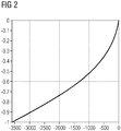
- FIG. 2 is an inverse representation of FIG. 1 , where only the curve with an acceleration value of 0.05 Hz / s is shown.
- the start differential angle is here compared to FIG. 1 set to -3600 ° to nominally reach a target dome angle of 0 °.
- the difference angle is plotted in degrees, whereby the integer multiples of 360 ° are added.
- the speed difference from gas turbine to steam turbine in Hz is plotted.
- FIG. 2 thus shows how with constant relative acceleration of 0.05 Hz / s the speed difference depends on the differential angle.
- a differential angle of 0 ° is assumed.
- the central setpoint curve For a selected acceleration of 0.05 Hz / s FIG. 2 the central setpoint curve.
- the speed difference between the gas and steam turbine should be at an angle difference of 900 ° -0.5 Hz. This means that with the angular difference of 900 °, the steam turbine is still 0.5 Hz slower than the gas turbine.
- FIG. 2 describes FIG. 2 the relationship between swept angle and speed difference between steam and gas turbine.
- the target angle 0 ° is not reached with a constant acceleration of 0.05 Hz / s, but a larger target angle. In this Case the steam turbine is too slow; it needs to be accelerated more. If, on the other hand, the difference in velocity is smaller for the real system with a measured difference angle of -900 °, the target angle 0 ° is not reached with a constant acceleration of 0.05 Hz / s, but a smaller target angle. In this case, the steam turbine is too fast, it must be braked.
- the engagement process as such is in FIG. 3 shown.
- the steam turbine is initially slower than the gas turbine, but is accelerated relative to this.
- the speed of the gas turbine is constant at 50 Hz, as shown by the dotted line.
- the speed of the steam turbine is shown by the solid line.
- FIG. 4 The effects of the engagement on the differential angle become FIG. 4 seen.
- the right-hand value axis again shows the time in seconds and the high-angle axis plots the rotation angle difference in degrees.
- the dashed line indicates a desired value of the angular difference, which is here at 0 °.
- the solid, initially running down line shows the time course of the actual angular difference.
- the rotation angle of the steam turbine is 250 ° smaller than the rotation angle of the gas turbine. This difference in rotational angle initially decreases rapidly to a difference of zero degrees. Thereafter, the rotational angle difference increases again, in this case by about 20 °. This is because when turning into the coupling sleeve, turning back the steam turbine about the Kupplungsverformatwinkel takes place.
- the course of the clutch torsion angle can be seen on the dotted line.
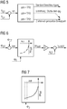
- FIGS. 5, 6 and 7 show schematically the scheme for performing the method described above.
- FIG. 5 gives an overview of the entire course of the startup of the steam turbine.
- a preset speed difference (1 Hz was selected here)
- the steam turbine is accelerated as usual over a specified ramp.
- a speed difference of 1Hz ie the output speed
- a changeover to the controlled-angle engagement takes place.
- the current angular difference in the range 0 ° - 360 ° is detected and reduced by the angular range that would pass the gas turbine while maintaining the previous acceleration of the steam turbine until the start of engagement.
- the speed difference between the gas and steam turbine is 1 Hz
- the steam turbine is accelerated at 0.05 Hz / s.
- the differential angle traveled is 3600 °.
- FIG. 6 describes the actual regulation of the target dome angle.
- the difference between Dampfturbinenverduswinkel and Gasturbinenverfitwinkel, ie the differential angle is converted by means of a characteristic curve in a target speed difference between steam and gas turbine.
- the target speed of the steam turbine is thus determined as a function of the gas turbine speed and the differential angle.
- the factor 'K' gives the additional possibility to further increase this target speed difference.
- the factor 'K' is the Feedback factor of the control difference, ie the deviation of the actual value from the setpoint. It is thus a P-controller. It must be separately analyzed and specified with regard to the properties of the resulting overall control loop.
Landscapes
- Engineering & Computer Science (AREA)
- General Engineering & Computer Science (AREA)
- Mechanical Engineering (AREA)
- Chemical & Material Sciences (AREA)
- Combustion & Propulsion (AREA)
- Physics & Mathematics (AREA)
- Fluid Mechanics (AREA)
- Control Of Turbines (AREA)
- Engine Equipment That Uses Special Cycles (AREA)
- Hydraulic Clutches, Magnetic Clutches, Fluid Clutches, And Fluid Joints (AREA)
Claims (7)
- Procédé d'accouplement d'un dispositif tournant,
notamment d'une turbine à vapeur,
et d'un dispositif à arbre,
notamment d'une turbine à gaz,
comprenant les stades suivants :- accélération du dispositif tournant jusqu'à une vitesse de rotation de sortie, qui est inférieure à la vitesse de rotation du dispositif à arbre ;- détermination d'une différence d'angle entre le dispositif à arbre et le dispositif tournant ;caractérisé par
l'accélération du dispositif tournant à une valeur d'accélération, qui est déduite d'une différence de vitesse de rotation de consigne prévue pour le début de l'opération d'accouplement entre le dispositif à arbre et le dispositif tournant, différence qui est formée en fonction de la différence d'angle détectée, de l'accélération jusqu'à la vitesse de rotation de sortie et d'un angle d'accouplement cible souhaité. - Procédé suivant la revendication 1,
caractérisé en ce que
pour un choix approprié de la différence de vitesse de rotation de sortie, on choisit, comme valeur d'accélération, la valeur avec laquelle l'accélération du dispositif tournant s'effectue jusqu'à la vitesse de rotation de sortie. - Procédé suivant l'une des revendications précédentes,
caractérisé en ce que
la vitesse de rotation de sortie est inférieure d'environ 1 Hz à la vitesse de rotation du dispositif à arbre, de préférence d'environ 0,5 Hz à environ 1,5 Hz, et d'une manière particulièrement préférée d'environ 0,9 Hz à environ 1,1 Hz. - Procédé suivant l'une des revendications précédentes,
caractérisé en ce que
pour un choix approprié de la différence de vitesse de rotation de sortie, la valeur d'accélération est d'environ 0,025 Hz/s à environ 0,075 Hz/s, de préférence d'environ 0,05 Hz/s. - Procédé suivant l'une des revendications précédentes,
caractérisé en ce que
dans la fixation de la valeur d'accélération à partir de la différence de vitesse de rotation de consigne, on prend en compte que, lors de l'accouplement, la différence d'angle se modifie d'un angle de torsion de l'accouplement. - Système comprenant un dispositif à arbre,
notamment une turbine à gaz,
un dispositif tournant,
notamment une turbine à vapeur,
comprenant un accouplement pour accoupler le dispositif à arbre et le dispositif de rotation, comprenant :un dispositif de détection de la différence d'angle entre le dispositif à arbre et le dispositif tournant,un dispositif d'accélération du dispositif tournant à une valeur d'accélération,des moyens, qui permettent, en fonction de la différence d'angle détectée, par fixation de la valeur d'accélération, d'atteindre un angle d'accouplement cible souhaité entre le dispositif à arbre et le dispositif tournant,caractérisé en ce quel'accélération du dispositif tournant à une valeur d'accélération, qui est déduite d'une différence de vitesse de rotation de consigne prévue pour le début de l'opération d'accouplement entre le dispositif à arbre et le dispositif tournant, différence qui est formée en fonction de la différence d'angle détectée de l'accélération jusqu'à la vitesse de rotation de sortie et d'un angle d'accouplement cible souhaité. - Système suivant la revendication 6,
caractérisé en ce que
la détection de la différence d'angle peut être déterminée à une cadence d'environ 4 ms à environ 20 ms ou plus petite.
Priority Applications (1)
| Application Number | Priority Date | Filing Date | Title |
|---|---|---|---|
| EP14732520.3A EP2984304B1 (fr) | 2013-06-14 | 2014-06-06 | Procédé de couplage d'une turbine à vapeur et d'une turbine à gaz avec un angle différentiel souhaité |
Applications Claiming Priority (3)
| Application Number | Priority Date | Filing Date | Title |
|---|---|---|---|
| EP13171947.8A EP2813675A1 (fr) | 2013-06-14 | 2013-06-14 | Procédé de couplage d'une turbine à vapeur et d'une turbine à gaz avec un angle différentiel souhaité |
| PCT/EP2014/061794 WO2014198649A1 (fr) | 2013-06-14 | 2014-06-06 | Procédé d'accouplement d'une turbine à vapeur et d'une turbine à gaz avec un écart angulaire souhaité |
| EP14732520.3A EP2984304B1 (fr) | 2013-06-14 | 2014-06-06 | Procédé de couplage d'une turbine à vapeur et d'une turbine à gaz avec un angle différentiel souhaité |
Publications (2)
| Publication Number | Publication Date |
|---|---|
| EP2984304A1 EP2984304A1 (fr) | 2016-02-17 |
| EP2984304B1 true EP2984304B1 (fr) | 2019-09-11 |
Family
ID=48669753
Family Applications (2)
| Application Number | Title | Priority Date | Filing Date |
|---|---|---|---|
| EP13171947.8A Withdrawn EP2813675A1 (fr) | 2013-06-14 | 2013-06-14 | Procédé de couplage d'une turbine à vapeur et d'une turbine à gaz avec un angle différentiel souhaité |
| EP14732520.3A Active EP2984304B1 (fr) | 2013-06-14 | 2014-06-06 | Procédé de couplage d'une turbine à vapeur et d'une turbine à gaz avec un angle différentiel souhaité |
Family Applications Before (1)
| Application Number | Title | Priority Date | Filing Date |
|---|---|---|---|
| EP13171947.8A Withdrawn EP2813675A1 (fr) | 2013-06-14 | 2013-06-14 | Procédé de couplage d'une turbine à vapeur et d'une turbine à gaz avec un angle différentiel souhaité |
Country Status (7)
| Country | Link |
|---|---|
| US (1) | US10309261B2 (fr) |
| EP (2) | EP2813675A1 (fr) |
| JP (1) | JP6227769B2 (fr) |
| KR (1) | KR101825311B1 (fr) |
| CN (1) | CN105308273B (fr) |
| RU (1) | RU2630054C2 (fr) |
| WO (1) | WO2014198649A1 (fr) |
Families Citing this family (7)
| Publication number | Priority date | Publication date | Assignee | Title |
|---|---|---|---|---|
| EP3130780A1 (fr) * | 2015-08-14 | 2017-02-15 | Siemens Aktiengesellschaft | Procede de couplage de deux demi-arbres |
| EP3232015A1 (fr) * | 2016-04-12 | 2017-10-18 | Siemens Aktiengesellschaft | Chaîne cinématique de turbomachine et procédé de couplage de la chaîne cinématique de turbomachine |
| EP3246536A1 (fr) * | 2016-05-17 | 2017-11-22 | Siemens Aktiengesellschaft | Procede de synchronisation d'une turbine au reseau electrique |
| EP3246538A1 (fr) * | 2016-05-18 | 2017-11-22 | Siemens Aktiengesellschaft | Procede de couplage d'une turbine a vapeur et d'une turbine a gaz avec reglage de l'angle differentiel souhaite a l'aide d'une acceleration de consigne |
| EP3252281A1 (fr) * | 2016-05-31 | 2017-12-06 | Siemens Aktiengesellschaft | Synchronisation d'une turbine a l'aide d'un reseau a courant alternatif selon une trajectoire theorique pour l'angle differentiel theorique |
| EP3511535A1 (fr) | 2018-01-10 | 2019-07-17 | Siemens Aktiengesellschaft | Installation et procédé de fonctionnement d'une installation |
| CN114486240B (zh) * | 2021-12-23 | 2024-04-19 | 华北电力科学研究院有限责任公司 | 一种用于汽轮机离合器的啮合方法及装置 |
Family Cites Families (15)
| Publication number | Priority date | Publication date | Assignee | Title |
|---|---|---|---|---|
| SU483337A1 (ru) | 1973-03-26 | 1975-09-05 | Волгоградское Отделение Государственного Ордена Трудового Красного Знамени Проектного Института "Тяжпромэлектропроект" | Устройство синхронизации механизмов передвижени крана |
| US3915271A (en) * | 1974-09-25 | 1975-10-28 | Koppers Co Inc | Method and apparatus for electronically controlling the engagement of coacting propulsion systems |
| DE3935450C1 (fr) | 1989-10-25 | 1991-05-23 | Heidelberger Druckmaschinen Ag, 6900 Heidelberg, De | |
| JP3701420B2 (ja) | 1996-11-28 | 2005-09-28 | 本田技研工業株式会社 | 車両用摩擦式クラッチの制御装置 |
| JPH10184317A (ja) * | 1996-12-26 | 1998-07-14 | Fuji Electric Co Ltd | 一軸型コンバインドサイクルプラント |
| JP4404324B2 (ja) * | 1999-11-19 | 2010-01-27 | 本田技研工業株式会社 | クラッチ接続制御装置 |
| JP2003013709A (ja) | 2001-06-28 | 2003-01-15 | Mitsubishi Heavy Ind Ltd | クラッチ嵌合検出装置及びこれを備えた一軸コンバインドプラント |
| JP3716244B2 (ja) | 2002-09-19 | 2005-11-16 | 三菱重工業株式会社 | クラッチを備えた一軸コンバインドプラントの運転制御装置及び運転制御方法。 |
| JP3930462B2 (ja) | 2003-08-01 | 2007-06-13 | 株式会社日立製作所 | 一軸コンバインドサイクル発電設備及びその運転方法 |
| JP2006063975A (ja) | 2004-07-28 | 2006-03-09 | Honda Motor Co Ltd | ガスタービンエンジンのセンサ出力監視装置 |
| EP1911939A1 (fr) | 2006-10-09 | 2008-04-16 | Siemens Aktiengesellschaft | Réglage de l'accouplement par l'angle d'accouplement |
| JP2008291839A (ja) | 2007-05-10 | 2008-12-04 | Ebara Corp | マイクロタービンコジェネレーションシステムの遠隔監視システムおよび故障診断方法 |
| CN101932914B (zh) * | 2008-02-01 | 2013-03-06 | 西门子公司 | 用于确定旋转角的方法 |
| US9752509B2 (en) * | 2013-08-27 | 2017-09-05 | Siemens Energy, Inc. | Method for controlling coupling of shafts between a first machine and a second machine using rotation speeds and angles |
| EP2910742A1 (fr) * | 2014-02-20 | 2015-08-26 | Siemens Aktiengesellschaft | Procédé de couplage d'une turbine à vapeur et d'une turbine à gaz avec un angle différentiel |
-
2013
- 2013-06-14 EP EP13171947.8A patent/EP2813675A1/fr not_active Withdrawn
-
2014
- 2014-06-06 KR KR1020167000605A patent/KR101825311B1/ko active Active
- 2014-06-06 CN CN201480033879.8A patent/CN105308273B/zh active Active
- 2014-06-06 EP EP14732520.3A patent/EP2984304B1/fr active Active
- 2014-06-06 WO PCT/EP2014/061794 patent/WO2014198649A1/fr not_active Ceased
- 2014-06-06 US US14/896,377 patent/US10309261B2/en active Active
- 2014-06-06 JP JP2016518943A patent/JP6227769B2/ja active Active
- 2014-06-06 RU RU2016100975A patent/RU2630054C2/ru active
Non-Patent Citations (1)
| Title |
|---|
| None * |
Also Published As
| Publication number | Publication date |
|---|---|
| JP6227769B2 (ja) | 2017-11-08 |
| US20160130983A1 (en) | 2016-05-12 |
| CN105308273B (zh) | 2017-09-05 |
| CN105308273A (zh) | 2016-02-03 |
| KR20160017085A (ko) | 2016-02-15 |
| RU2630054C2 (ru) | 2017-09-05 |
| WO2014198649A1 (fr) | 2014-12-18 |
| RU2016100975A (ru) | 2017-07-19 |
| EP2813675A1 (fr) | 2014-12-17 |
| US10309261B2 (en) | 2019-06-04 |
| JP2016528415A (ja) | 2016-09-15 |
| KR101825311B1 (ko) | 2018-03-14 |
| EP2984304A1 (fr) | 2016-02-17 |
Similar Documents
| Publication | Publication Date | Title |
|---|---|---|
| EP2984304B1 (fr) | Procédé de couplage d'une turbine à vapeur et d'une turbine à gaz avec un angle différentiel souhaité | |
| EP2324291B1 (fr) | Installation de combustion avec système de sécurité et procédé de fonctionnement de celle-ci | |
| DE60305768T2 (de) | Steuerflächensteuerungen für ein Flugzeug sowie dazugehöriges Verfahren | |
| AT518700A1 (de) | Verfahren zum Eindrehen einer Schraube mit einem vorbestimmten Anzugsdrehmoment | |
| DE69204070T2 (de) | Hubschraubermotorsteuerung mit von der zyklischen blattwinkeländerung in querrichtung abhängigem vorhersagewert. | |
| WO2015158344A2 (fr) | Procédé de réduction de vibrations de broutage d'un embrayage à friction dans une chaîne cinématique d'un véhicule automobile | |
| EP3080409B1 (fr) | Procédé de couplage d'une turbine à vapeur et d'une turbine à gaz avec un angle différentiel | |
| DE3023550A1 (de) | Steuersystem zur steuerung der kraftstoffzufuhr bei einer gasturbine | |
| DE102015010686A1 (de) | Verfahren und System zur Überwachung einer Einzelblattverstellung einer Windenergieanlage | |
| DE102007010768A1 (de) | Verfahren für die Optimierung der Ventilstellung und der Pumpendrehzahl in einem Ventilsystem mit PID-Regelung ohne die Verwendung externer Signale | |
| DE3425445C2 (fr) | ||
| AT509381B1 (de) | Prüfstand für dynamische prüfaufgaben an verbrennungskraftmaschinen, sowie verfahren zum betreiben eines derartigen prüfstandes | |
| EP3464862B1 (fr) | Procédé et dispositif d'étalonnage d'un système d'actionneur | |
| EP3245730A1 (fr) | Dispositif d'entraînement avec estimation du moment d'inertie | |
| DE2852911A1 (de) | Verfahren und vorrichtung fuer schnelle schuberhoehungen in einem turbofan-triebwerk | |
| EP3426897B1 (fr) | Procede de couplage d'une turbine a vapeur et d'une turbine a gaz avec reglage de l'angle differentiel souhaite a l'aide d'une acceleration de consigne | |
| DE102010046669A1 (de) | Verfahren zur Steuerung eines drehzahladaptiven Tilgers | |
| DE102016213720A1 (de) | System zur Datenübermittlung und -verarbeitung zur Regelung eines Rotorblattaktuators | |
| DE102007008613B4 (de) | Antriebsvorrichtung sowie Verfahren zum Antreiben eiens Fahrzeugs | |
| EP3238338B1 (fr) | Procédé et dispositif de surveillance du fonctionnement d'une installation de production d'électricité | |
| EP3296755B1 (fr) | Détermination d'ampleurs de charge en cours de fonctionnement | |
| DE10196104B4 (de) | Graphitkörper imprägniert mit einer Leichtmetall-Legierung, Verfahren zu dessen Herstellung und seine Verwendung | |
| WO2016004938A1 (fr) | Procédé permettant de faire fonctionner un déphaseur d'arbre à cames et dispositif de régulation d'un déphaseur d'arbre à cames | |
| WO2016055039A2 (fr) | Groupe propulseur de bateau et procédé de fonctionnement du groupe propulseur | |
| EP4134201B1 (fr) | Procédé de régulation d'une visseuse |
Legal Events
| Date | Code | Title | Description |
|---|---|---|---|
| PUAI | Public reference made under article 153(3) epc to a published international application that has entered the european phase |
Free format text: ORIGINAL CODE: 0009012 |
|
| 17P | Request for examination filed |
Effective date: 20151111 |
|
| AK | Designated contracting states |
Kind code of ref document: A1 Designated state(s): AL AT BE BG CH CY CZ DE DK EE ES FI FR GB GR HR HU IE IS IT LI LT LU LV MC MK MT NL NO PL PT RO RS SE SI SK SM TR |
|
| AX | Request for extension of the european patent |
Extension state: BA ME |
|
| DAX | Request for extension of the european patent (deleted) | ||
| RAP1 | Party data changed (applicant data changed or rights of an application transferred) |
Owner name: SIEMENS AKTIENGESELLSCHAFT |
|
| STAA | Information on the status of an ep patent application or granted ep patent |
Free format text: STATUS: EXAMINATION IS IN PROGRESS |
|
| 17Q | First examination report despatched |
Effective date: 20180605 |
|
| RIC1 | Information provided on ipc code assigned before grant |
Ipc: F02C 7/26 20060101ALI20190214BHEP Ipc: F01K 23/16 20060101AFI20190214BHEP Ipc: F16D 48/00 20060101ALI20190214BHEP Ipc: F01D 19/00 20060101ALI20190214BHEP Ipc: F02C 6/18 20060101ALI20190214BHEP |
|
| GRAP | Despatch of communication of intention to grant a patent |
Free format text: ORIGINAL CODE: EPIDOSNIGR1 |
|
| STAA | Information on the status of an ep patent application or granted ep patent |
Free format text: STATUS: GRANT OF PATENT IS INTENDED |
|
| INTG | Intention to grant announced |
Effective date: 20190408 |
|
| GRAS | Grant fee paid |
Free format text: ORIGINAL CODE: EPIDOSNIGR3 |
|
| GRAA | (expected) grant |
Free format text: ORIGINAL CODE: 0009210 |
|
| STAA | Information on the status of an ep patent application or granted ep patent |
Free format text: STATUS: THE PATENT HAS BEEN GRANTED |
|
| AK | Designated contracting states |
Kind code of ref document: B1 Designated state(s): AL AT BE BG CH CY CZ DE DK EE ES FI FR GB GR HR HU IE IS IT LI LT LU LV MC MK MT NL NO PL PT RO RS SE SI SK SM TR |
|
| REG | Reference to a national code |
Ref country code: GB Ref legal event code: FG4D Free format text: NOT ENGLISH |
|
| REG | Reference to a national code |
Ref country code: CH Ref legal event code: EP |
|
| REG | Reference to a national code |
Ref country code: AT Ref legal event code: REF Ref document number: 1178726 Country of ref document: AT Kind code of ref document: T Effective date: 20190915 |
|
| REG | Reference to a national code |
Ref country code: DE Ref legal event code: R096 Ref document number: 502014012626 Country of ref document: DE Ref country code: IE Ref legal event code: FG4D Free format text: LANGUAGE OF EP DOCUMENT: GERMAN |
|
| REG | Reference to a national code |
Ref country code: NL Ref legal event code: MP Effective date: 20190911 |
|
| REG | Reference to a national code |
Ref country code: LT Ref legal event code: MG4D |
|
| PG25 | Lapsed in a contracting state [announced via postgrant information from national office to epo] |
Ref country code: FI Free format text: LAPSE BECAUSE OF FAILURE TO SUBMIT A TRANSLATION OF THE DESCRIPTION OR TO PAY THE FEE WITHIN THE PRESCRIBED TIME-LIMIT Effective date: 20190911 Ref country code: NO Free format text: LAPSE BECAUSE OF FAILURE TO SUBMIT A TRANSLATION OF THE DESCRIPTION OR TO PAY THE FEE WITHIN THE PRESCRIBED TIME-LIMIT Effective date: 20191211 Ref country code: HR Free format text: LAPSE BECAUSE OF FAILURE TO SUBMIT A TRANSLATION OF THE DESCRIPTION OR TO PAY THE FEE WITHIN THE PRESCRIBED TIME-LIMIT Effective date: 20190911 Ref country code: LT Free format text: LAPSE BECAUSE OF FAILURE TO SUBMIT A TRANSLATION OF THE DESCRIPTION OR TO PAY THE FEE WITHIN THE PRESCRIBED TIME-LIMIT Effective date: 20190911 Ref country code: BG Free format text: LAPSE BECAUSE OF FAILURE TO SUBMIT A TRANSLATION OF THE DESCRIPTION OR TO PAY THE FEE WITHIN THE PRESCRIBED TIME-LIMIT Effective date: 20191211 Ref country code: SE Free format text: LAPSE BECAUSE OF FAILURE TO SUBMIT A TRANSLATION OF THE DESCRIPTION OR TO PAY THE FEE WITHIN THE PRESCRIBED TIME-LIMIT Effective date: 20190911 |
|
| PG25 | Lapsed in a contracting state [announced via postgrant information from national office to epo] |
Ref country code: GR Free format text: LAPSE BECAUSE OF FAILURE TO SUBMIT A TRANSLATION OF THE DESCRIPTION OR TO PAY THE FEE WITHIN THE PRESCRIBED TIME-LIMIT Effective date: 20191212 Ref country code: LV Free format text: LAPSE BECAUSE OF FAILURE TO SUBMIT A TRANSLATION OF THE DESCRIPTION OR TO PAY THE FEE WITHIN THE PRESCRIBED TIME-LIMIT Effective date: 20190911 Ref country code: AL Free format text: LAPSE BECAUSE OF FAILURE TO SUBMIT A TRANSLATION OF THE DESCRIPTION OR TO PAY THE FEE WITHIN THE PRESCRIBED TIME-LIMIT Effective date: 20190911 Ref country code: RS Free format text: LAPSE BECAUSE OF FAILURE TO SUBMIT A TRANSLATION OF THE DESCRIPTION OR TO PAY THE FEE WITHIN THE PRESCRIBED TIME-LIMIT Effective date: 20190911 Ref country code: ES Free format text: LAPSE BECAUSE OF FAILURE TO SUBMIT A TRANSLATION OF THE DESCRIPTION OR TO PAY THE FEE WITHIN THE PRESCRIBED TIME-LIMIT Effective date: 20190911 |
|
| REG | Reference to a national code |
Ref country code: CH Ref legal event code: NV Representative=s name: SIEMENS SCHWEIZ AG, CH |
|
| PG25 | Lapsed in a contracting state [announced via postgrant information from national office to epo] |
Ref country code: IT Free format text: LAPSE BECAUSE OF FAILURE TO SUBMIT A TRANSLATION OF THE DESCRIPTION OR TO PAY THE FEE WITHIN THE PRESCRIBED TIME-LIMIT Effective date: 20190911 Ref country code: RO Free format text: LAPSE BECAUSE OF FAILURE TO SUBMIT A TRANSLATION OF THE DESCRIPTION OR TO PAY THE FEE WITHIN THE PRESCRIBED TIME-LIMIT Effective date: 20190911 Ref country code: PT Free format text: LAPSE BECAUSE OF FAILURE TO SUBMIT A TRANSLATION OF THE DESCRIPTION OR TO PAY THE FEE WITHIN THE PRESCRIBED TIME-LIMIT Effective date: 20200113 Ref country code: PL Free format text: LAPSE BECAUSE OF FAILURE TO SUBMIT A TRANSLATION OF THE DESCRIPTION OR TO PAY THE FEE WITHIN THE PRESCRIBED TIME-LIMIT Effective date: 20190911 Ref country code: NL Free format text: LAPSE BECAUSE OF FAILURE TO SUBMIT A TRANSLATION OF THE DESCRIPTION OR TO PAY THE FEE WITHIN THE PRESCRIBED TIME-LIMIT Effective date: 20190911 Ref country code: EE Free format text: LAPSE BECAUSE OF FAILURE TO SUBMIT A TRANSLATION OF THE DESCRIPTION OR TO PAY THE FEE WITHIN THE PRESCRIBED TIME-LIMIT Effective date: 20190911 |
|
| PG25 | Lapsed in a contracting state [announced via postgrant information from national office to epo] |
Ref country code: IS Free format text: LAPSE BECAUSE OF FAILURE TO SUBMIT A TRANSLATION OF THE DESCRIPTION OR TO PAY THE FEE WITHIN THE PRESCRIBED TIME-LIMIT Effective date: 20200224 Ref country code: SM Free format text: LAPSE BECAUSE OF FAILURE TO SUBMIT A TRANSLATION OF THE DESCRIPTION OR TO PAY THE FEE WITHIN THE PRESCRIBED TIME-LIMIT Effective date: 20190911 Ref country code: SK Free format text: LAPSE BECAUSE OF FAILURE TO SUBMIT A TRANSLATION OF THE DESCRIPTION OR TO PAY THE FEE WITHIN THE PRESCRIBED TIME-LIMIT Effective date: 20190911 |
|
| REG | Reference to a national code |
Ref country code: DE Ref legal event code: R097 Ref document number: 502014012626 Country of ref document: DE |
|
| PLBE | No opposition filed within time limit |
Free format text: ORIGINAL CODE: 0009261 |
|
| STAA | Information on the status of an ep patent application or granted ep patent |
Free format text: STATUS: NO OPPOSITION FILED WITHIN TIME LIMIT |
|
| PG2D | Information on lapse in contracting state deleted |
Ref country code: IS |
|
| PG25 | Lapsed in a contracting state [announced via postgrant information from national office to epo] |
Ref country code: DK Free format text: LAPSE BECAUSE OF FAILURE TO SUBMIT A TRANSLATION OF THE DESCRIPTION OR TO PAY THE FEE WITHIN THE PRESCRIBED TIME-LIMIT Effective date: 20190911 Ref country code: IS Free format text: LAPSE BECAUSE OF FAILURE TO SUBMIT A TRANSLATION OF THE DESCRIPTION OR TO PAY THE FEE WITHIN THE PRESCRIBED TIME-LIMIT Effective date: 20200112 |
|
| 26N | No opposition filed |
Effective date: 20200615 |
|
| PG25 | Lapsed in a contracting state [announced via postgrant information from national office to epo] |
Ref country code: SI Free format text: LAPSE BECAUSE OF FAILURE TO SUBMIT A TRANSLATION OF THE DESCRIPTION OR TO PAY THE FEE WITHIN THE PRESCRIBED TIME-LIMIT Effective date: 20190911 |
|
| REG | Reference to a national code |
Ref country code: DE Ref legal event code: R119 Ref document number: 502014012626 Country of ref document: DE |
|
| PG25 | Lapsed in a contracting state [announced via postgrant information from national office to epo] |
Ref country code: MC Free format text: LAPSE BECAUSE OF FAILURE TO SUBMIT A TRANSLATION OF THE DESCRIPTION OR TO PAY THE FEE WITHIN THE PRESCRIBED TIME-LIMIT Effective date: 20190911 |
|
| REG | Reference to a national code |
Ref country code: CH Ref legal event code: PL |
|
| GBPC | Gb: european patent ceased through non-payment of renewal fee |
Effective date: 20200606 |
|
| PG25 | Lapsed in a contracting state [announced via postgrant information from national office to epo] |
Ref country code: LU Free format text: LAPSE BECAUSE OF NON-PAYMENT OF DUE FEES Effective date: 20200606 |
|
| REG | Reference to a national code |
Ref country code: BE Ref legal event code: MM Effective date: 20200630 |
|
| PG25 | Lapsed in a contracting state [announced via postgrant information from national office to epo] |
Ref country code: CH Free format text: LAPSE BECAUSE OF NON-PAYMENT OF DUE FEES Effective date: 20200630 Ref country code: IE Free format text: LAPSE BECAUSE OF NON-PAYMENT OF DUE FEES Effective date: 20200606 Ref country code: GB Free format text: LAPSE BECAUSE OF NON-PAYMENT OF DUE FEES Effective date: 20200606 Ref country code: LI Free format text: LAPSE BECAUSE OF NON-PAYMENT OF DUE FEES Effective date: 20200630 |
|
| PG25 | Lapsed in a contracting state [announced via postgrant information from national office to epo] |
Ref country code: BE Free format text: LAPSE BECAUSE OF NON-PAYMENT OF DUE FEES Effective date: 20200630 Ref country code: DE Free format text: LAPSE BECAUSE OF NON-PAYMENT OF DUE FEES Effective date: 20210101 |
|
| REG | Reference to a national code |
Ref country code: AT Ref legal event code: MM01 Ref document number: 1178726 Country of ref document: AT Kind code of ref document: T Effective date: 20200606 |
|
| PG25 | Lapsed in a contracting state [announced via postgrant information from national office to epo] |
Ref country code: AT Free format text: LAPSE BECAUSE OF NON-PAYMENT OF DUE FEES Effective date: 20200606 |
|
| PG25 | Lapsed in a contracting state [announced via postgrant information from national office to epo] |
Ref country code: TR Free format text: LAPSE BECAUSE OF FAILURE TO SUBMIT A TRANSLATION OF THE DESCRIPTION OR TO PAY THE FEE WITHIN THE PRESCRIBED TIME-LIMIT Effective date: 20190911 Ref country code: MT Free format text: LAPSE BECAUSE OF FAILURE TO SUBMIT A TRANSLATION OF THE DESCRIPTION OR TO PAY THE FEE WITHIN THE PRESCRIBED TIME-LIMIT Effective date: 20190911 Ref country code: CY Free format text: LAPSE BECAUSE OF FAILURE TO SUBMIT A TRANSLATION OF THE DESCRIPTION OR TO PAY THE FEE WITHIN THE PRESCRIBED TIME-LIMIT Effective date: 20190911 |
|
| PG25 | Lapsed in a contracting state [announced via postgrant information from national office to epo] |
Ref country code: MK Free format text: LAPSE BECAUSE OF FAILURE TO SUBMIT A TRANSLATION OF THE DESCRIPTION OR TO PAY THE FEE WITHIN THE PRESCRIBED TIME-LIMIT Effective date: 20190911 |
|
| PGFP | Annual fee paid to national office [announced via postgrant information from national office to epo] |
Ref country code: FR Payment date: 20250624 Year of fee payment: 12 |
|
| PGFP | Annual fee paid to national office [announced via postgrant information from national office to epo] |
Ref country code: CZ Payment date: 20250528 Year of fee payment: 12 |