EP2984331B1 - Dispositif et procédé de réduction de variations de pression dans un tuyau d'admission d'une turbine hydraulique, d'une pompe à eau ou d'une pompe-turbine à eau - Google Patents
Dispositif et procédé de réduction de variations de pression dans un tuyau d'admission d'une turbine hydraulique, d'une pompe à eau ou d'une pompe-turbine à eau Download PDFInfo
- Publication number
- EP2984331B1 EP2984331B1 EP14706010.7A EP14706010A EP2984331B1 EP 2984331 B1 EP2984331 B1 EP 2984331B1 EP 14706010 A EP14706010 A EP 14706010A EP 2984331 B1 EP2984331 B1 EP 2984331B1
- Authority
- EP
- European Patent Office
- Prior art keywords
- displacer
- water pump
- turbine
- suction pipe
- water
- Prior art date
- Legal status (The legal status is an assumption and is not a legal conclusion. Google has not performed a legal analysis and makes no representation as to the accuracy of the status listed.)
- Active
Links
- XLYOFNOQVPJJNP-UHFFFAOYSA-N water Substances O XLYOFNOQVPJJNP-UHFFFAOYSA-N 0.000 title claims description 37
- 238000000034 method Methods 0.000 title claims description 12
- 230000001105 regulatory effect Effects 0.000 claims 1
- 238000006073 displacement reaction Methods 0.000 description 46
- 230000001419 dependent effect Effects 0.000 description 4
- 230000014509 gene expression Effects 0.000 description 4
- 238000009434 installation Methods 0.000 description 2
- 230000006978 adaptation Effects 0.000 description 1
- 238000013459 approach Methods 0.000 description 1
- 230000015572 biosynthetic process Effects 0.000 description 1
- 230000002349 favourable effect Effects 0.000 description 1
- 239000000463 material Substances 0.000 description 1
- 238000007789 sealing Methods 0.000 description 1
Images


Classifications
-
- F—MECHANICAL ENGINEERING; LIGHTING; HEATING; WEAPONS; BLASTING
- F03—MACHINES OR ENGINES FOR LIQUIDS; WIND, SPRING, OR WEIGHT MOTORS; PRODUCING MECHANICAL POWER OR A REACTIVE PROPULSIVE THRUST, NOT OTHERWISE PROVIDED FOR
- F03B—MACHINES OR ENGINES FOR LIQUIDS
- F03B3/00—Machines or engines of reaction type; Parts or details peculiar thereto
- F03B3/02—Machines or engines of reaction type; Parts or details peculiar thereto with radial flow at high-pressure side and axial flow at low-pressure side of rotors, e.g. Francis turbines
-
- F—MECHANICAL ENGINEERING; LIGHTING; HEATING; WEAPONS; BLASTING
- F03—MACHINES OR ENGINES FOR LIQUIDS; WIND, SPRING, OR WEIGHT MOTORS; PRODUCING MECHANICAL POWER OR A REACTIVE PROPULSIVE THRUST, NOT OTHERWISE PROVIDED FOR
- F03B—MACHINES OR ENGINES FOR LIQUIDS
- F03B11/00—Parts or details not provided for in, or of interest apart from, the preceding groups, e.g. wear-protection couplings, between turbine and generator
- F03B11/04—Parts or details not provided for in, or of interest apart from, the preceding groups, e.g. wear-protection couplings, between turbine and generator for diminishing cavitation or vibration, e.g. balancing
-
- F—MECHANICAL ENGINEERING; LIGHTING; HEATING; WEAPONS; BLASTING
- F03—MACHINES OR ENGINES FOR LIQUIDS; WIND, SPRING, OR WEIGHT MOTORS; PRODUCING MECHANICAL POWER OR A REACTIVE PROPULSIVE THRUST, NOT OTHERWISE PROVIDED FOR
- F03B—MACHINES OR ENGINES FOR LIQUIDS
- F03B3/00—Machines or engines of reaction type; Parts or details peculiar thereto
- F03B3/12—Blades; Blade-carrying rotors
- F03B3/125—Rotors for radial flow at high-pressure side and axial flow at low-pressure side, e.g. for Francis-type turbines
-
- F—MECHANICAL ENGINEERING; LIGHTING; HEATING; WEAPONS; BLASTING
- F05—INDEXING SCHEMES RELATING TO ENGINES OR PUMPS IN VARIOUS SUBCLASSES OF CLASSES F01-F04
- F05B—INDEXING SCHEME RELATING TO WIND, SPRING, WEIGHT, INERTIA OR LIKE MOTORS, TO MACHINES OR ENGINES FOR LIQUIDS COVERED BY SUBCLASSES F03B, F03D AND F03G
- F05B2250/00—Geometry
- F05B2250/40—Movement of component
-
- F—MECHANICAL ENGINEERING; LIGHTING; HEATING; WEAPONS; BLASTING
- F05—INDEXING SCHEMES RELATING TO ENGINES OR PUMPS IN VARIOUS SUBCLASSES OF CLASSES F01-F04
- F05B—INDEXING SCHEME RELATING TO WIND, SPRING, WEIGHT, INERTIA OR LIKE MOTORS, TO MACHINES OR ENGINES FOR LIQUIDS COVERED BY SUBCLASSES F03B, F03D AND F03G
- F05B2260/00—Function
- F05B2260/96—Preventing, counteracting or reducing vibration or noise
-
- Y—GENERAL TAGGING OF NEW TECHNOLOGICAL DEVELOPMENTS; GENERAL TAGGING OF CROSS-SECTIONAL TECHNOLOGIES SPANNING OVER SEVERAL SECTIONS OF THE IPC; TECHNICAL SUBJECTS COVERED BY FORMER USPC CROSS-REFERENCE ART COLLECTIONS [XRACs] AND DIGESTS
- Y02—TECHNOLOGIES OR APPLICATIONS FOR MITIGATION OR ADAPTATION AGAINST CLIMATE CHANGE
- Y02E—REDUCTION OF GREENHOUSE GAS [GHG] EMISSIONS, RELATED TO ENERGY GENERATION, TRANSMISSION OR DISTRIBUTION
- Y02E10/00—Energy generation through renewable energy sources
- Y02E10/20—Hydro energy
Definitions
- the invention relates to a turbine or pump or pump turbine, in particular the intake manifold of such a turbine, which serves to divert the water from the turbine towards underwater.
- the invention relates primarily to machines with wheels of the Francis type. But there are also machines with Kaplan wheels into consideration.
- Francis turbines are adapted to different operating conditions by adjusting the vanes.
- the effluent water is deflected below the impeller within the intake manifold through the manifold.
- Saugrohrkrümmer and the subsequent intake manifold diffuser unfavorable flow conditions that can lead to strong vibrations on the machine. Material damage as a result can occur in particular if the natural frequencies of components match the frequencies of these vibrations. Under the unfavorable flow conditions, the effectiveness of the machine suffers.
- elongate displacement body are arranged in the suction pipe.
- These displacement bodies are located in the extension of the machine axis and can be rotationally symmetrical, for example cylindrical, or else conical. These can both start from the impeller hub and be fastened there, or emanate from the suction pipe and be attached to this.
- the disadvantage of the known from the prior art solutions is that the said bodies remain not only in the operating conditions in which said unfavorable flow conditions, but also in operating conditions in which they do not occur in the flow. Although these problems are largely eliminated, but on the other hand, the flow obstructed in the unproblematic operating conditions, since without these bodies in these operating conditions, a higher efficiency of the machine could be achieved.
- a conical adjustment which is located below the rotor.
- the upper end of the conical adjusting device extends into the suction pipe.
- the conical adjusting device is provided with a lifting device. When the flow of water through the turbine is low, the lifting device is actuated and the adjusting device raised, so as to positively influence the water flow in the above sense. This achieves a certain adaptation to the different operating conditions.
- the conical adjusting device extends into the intake manifold in any case, that is to say even under operating conditions with favorable flow conditions, the flow through the conical adjusting device in these operating states is impeded.
- the inventors have set themselves the task of having to deal with the unfavorable flow conditions that arise in certain operating conditions without compromising the other operating conditions.
- this object can be achieved in that at least one suitable displacement body is introduced into the space of the suction pipe in operating conditions that have unfavorable flow conditions, which extends in the extension of the impeller axis. However, this displacement body is completely removed from the flow path in the other operating states.
- the quantity of operating states in which no unfavorable flow conditions in the above-mentioned sense occur is referred to as optimal operating range in the further course of this document.
- the optimum operating range is usually the operating range for which the hydraulic machine has been mainly designed and in which it achieves maximum efficiency. It is quite conceivable that the optimum operating range comprises a larger range of water flow rate, and that this area may be composed of several subregions, which are not necessarily connected to each other contiguous. Furthermore, it is quite possible for the hydraulic machine to reach the same or approximately the same maximum efficiency as in the region of the optimum operating range even in an operating state deviating from the optimum operating range. Among other things it is Object of this invention to seek exactly this. Furthermore, it is quite possible that the mentioned maximum efficiency is only achieved in a part of the range of the optimum operating range understood in the above sense, and the efficiency in the remaining range of the optimum operating range is lower.
- the inventors have recognized that it is advantageous if the size of the space occupied by the respective displacement body in the intake manifold is infinitely adjustable depending on the respective operating state.
- a displacement body is extended from the turbine hub and introduced in the operating areas that do not belong to the optimum operating range in the space of the suction tube, which extends in the extension of the Laufradachs. In the optimum operating range, however, the displacement body is completely sunk in the impeller hub and thus removed from the flow path.
- This first form of expression alone does not belong to the present invention.
- a columnar displacement body is extended from the edge of the suction tube and introduced in the operating areas that do not belong to the optimum operating range in the space of the suction tube, which extends in the extension of Laufradachs.
- This form of expression is mainly but not exclusively used in machines with vertical shaft and a suction pipe, which deflects the water flow substantially by 90 ° (ie, from vertical flow direction in the horizontal flow direction).
- the column body can have any cross-sectional area. In the optimal operating range of the columnar displacement body, however, completely moved out of the suction pipe and thus removed from the flow path.
- the inventors have also recognized that the optimal use of the device according to the invention consists in a method which is described by the characterizing features of the independent method claim.
- FIG. 1 In the presentation of the FIG. 1 is a section shown by a Francis turbine.
- the turbine shown has an impeller 10 with impeller hub 11 which is rotatably mounted about the impeller axis 12, a nozzle with a plurality of vanes 13 which are movable and with the aid of which the water flow rate can be adjusted. Furthermore, the turbine has a suction pipe 14.
- the turbine shown has a displacement body 15. For better visibility of the displacement body 15 is shown hatched in the figure. The part of the displacement body 15, which is not located in the suction pipe 14 is drawn with a dashed border.
- the displacement body 15 is inserted in operating conditions that deviate from the optimum operating range, from the impeller hub in the extension of the impeller shaft 12 in the intake manifold 14 and sunk completely in the optimum operating range in the impeller hub, so that no part of the displacement body 15 remains in the intake manifold 14.
- a corresponding opening and seals are provided in the impeller hub 13, which allow a extension and retraction of the displacement body 15.
- the size of the space occupied by the displacement body 15 in the intake manifold 14 is directly related to the length of the displacement body, which protrudes from the impeller hub.
- the end of the displacement body 15, which is in the extended state farthest from the impeller hub is designed so that it forms the outer surface of the hub in the retracted state and the hydraulic contour of the hub seamlessly adapts, so that in the optimum operating range, no hydraulic losses can occur.
- the shaft on which the impeller is mounted may be hollow, so that the displacement body 15 is in the retracted state at least partially in the cavity of the shaft.
- the displacement body 15 rotates together with the impeller, but it is also conceivable that the displacement body 15 does not rotate together with the impeller, but remains immobile relative to the suction pipe.
- the formation of the displacement body 15 is particularly useful as a cylindrical column, since this sealing is particularly easy to accomplish.
- the displacement body 15 is formed columnar with an arbitrary cross-section. The arrangement off FIG. 1 by itself does not belong to the present invention.
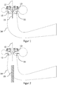
- FIG. 2 a section through a Francis turbine according to the invention is shown.
- the designations 10, 11, 12, 13 and 14 designate the same elements of the turbine as in FIG FIG. 1 described.
- the illustrated turbine has a displacement body 25 according to the invention.
- the displacement body 25 is introduced from the edge of the suction tube into the region of the suction tube, which lies in the axial extension of the impeller.
- the displacement body 25 has a columnar shape.
- a columnar shape is understood to mean a body which has the following property in a spatial direction, which is hereinafter referred to as the axis of the body. Through the axis of the body and a certain fixed angle relative to this axis, a Set of cutting planes. It then has the sectional area (cross-sectional area) of the columnar body in each of these sectional planes of the same shape. If the angle is 90 °, this is called a vertical column. If the angle deviates from 90 °, this is called a leaning column.
- the cross-sectional area of the column may have any shape. It should be noted that the definition given above does not apply to the ends of the column must be more strictly met, so that here, for example, a somewhat curved end surface can be present.
- the columnar shape of the displacement body 25 allows retraction and extension of the body along its axis, without causing leaks through which water can escape from the suction tube.
- appropriate seals between the displacement body and the suction pipe are provided.
- Particularly easy to implement is the so-called circular column, i. a column having circular cross-sectional areas, and more preferably, the vertical circular column, i. the cylinder (according to claim 4). With a circular cross-section, the seal can be realized particularly inexpensively.
- the axis of the columnar displacement body is substantially coaxial with the axis of rotation of the impeller, since in this arrangement, the hydraulic disturbances in the operating conditions, which deviate from the optimum operating range, can be suppressed particularly well.
- the end of the displacement body 25, which is the furthest removed from the Saugrohrrand in the extended state, is designed so that it forms the surface of the suction tube in the retracted state and the hydraulic contour of the suction tube seamlessly adapts, so that in Optimal operating range no hydraulic losses can occur.
- the displacement body 25 which is introduced from the Saugrohrrand, as far as can protrude into the suction pipe, that it is in the immediate vicinity of the impeller hub 11.
- FIG. 3 In the presentation of the FIG. 3 is a section through a Francis turbine according to the invention shown, in which the embodiments of FIGS. 1 and 2 can be seen in combination.
- the designations 10, 11, 12, 13 and 14 designate the same elements of the turbine as in FIG FIG. 1 described.
- the two displacement bodies 15 and 25 can come so close that they touch. This is particularly useful when the displacement body 15 does not rotate together with the impeller 10. If the displacement body 15 rotates together with the impeller 10, a sufficiently wider gap between the two displacement bodies 15 and 25 must remain.
- FIG. 4 a section through an inventive arrangement is shown, which consists of four displacement bodies (40, 41, 42 and 43).
- the left part of the figure shows the side view and the right part of the figure the view from above.
- the four displacement bodies are mutually comprehensive columns, which can be moved from the edge of the suction tube 14 into the inner region of the suction tube.
- Each of the four displacement body is individually movable.
- a variety of complex arrangements of displacement bodies in the intake manifold can be realized, depending on the distance by which the individual displacement body are retracted into the intake manifold.
- FIG. 4 results in a stepped pyramidal arrangement of the 4 displacement body.
- the number of displacement body is not limited to 4, but can be arbitrarily selected depending on the hydraulic requirements. In this way, the efficiency and smoothness in operating conditions that are outside the optimum operating range, can be further increased.
- Saugrohrrand 14 is shown horizontally. In reality, however, other courses of the Saugrohrrandes 14 may be present.
- the displacement body does not comprise each other, but they can also be moved side by side in any arrangement from the suction pipe edge 14 into the interior.
- V1 designates the initialization of the operating states.
- V2 indicates the setting of an operating condition.
- the loop around V2 indicates that this step can be repeated as desired during operation of the system, which is implemented as a function of the operating state by means of a turbine controller or a program stored in the controller.
- V1 on the other hand, is usually carried out once during or before commissioning of the system. However, circumstances may also occur which necessitate a repeated execution of V1, eg in the event of changes in the plant layout or an overhaul of the plant.
- the dependent method claims indicate appropriate expressions of V1. Which characteristic is particularly advantageous depends on the particular system and the hydraulic conditions of the system.
- the said series of tests may be a series of tests carried out on the completed installation itself or a series of tests carried out on a possibly smaller model of the installation or on a prototype.
- vibration it may be e.g. to act on shaft or bearing vibrations.
Landscapes
- Engineering & Computer Science (AREA)
- Chemical & Material Sciences (AREA)
- Combustion & Propulsion (AREA)
- Mechanical Engineering (AREA)
- General Engineering & Computer Science (AREA)
- Hydraulic Turbines (AREA)
Claims (11)
- Turbine hydraulique ou pompe à eau ou turbine à pompe à eau comprenant une roue à aubes (10) pourvue d'une pluralité d'aubes mobiles et d'un moyeu (11), un carter comportant un appareil de commande destiné à la régulation du flux d'eau passant à travers la roue à aubes, un tuyau d'admission (14) destiné à acheminer l'eau s'écoulant à travers la roue à aubes (10) et au moins un corps de déplacement (25) qui peut être introduit de manière réversible dans la zone du tuyau d'admission (14) et qui s'étend suivant l'allongement axial de la roue à aubes (10), dans lequel le corps de déplacement (25) peut être introduit par le bord du tuyau d'admission dans l'espace du tuyau d'admission, caractérisée en ce que le corps de déplacement (25) présente la forme d'une colonne et en ce que son axe s'étend de manière sensiblement coaxiale à l'axe de rotation (12) de la roue à aubes (10).
- Turbine hydraulique ou pompe à eau ou turbine à pompe à eau selon la revendication 1, caractérisée en ce que la taille d'au moins un corps de déplacement (25) peut être réglée dans le tuyau d'admission (14).
- Turbine hydraulique ou pompe à eau ou turbine à pompe à eau selon l'une quelconque des revendications 1 ou 2, caractérisée en ce que la taille d'au moins un corps de déplacement (25) peut être réglée pas à pas dans le tuyau d'admission (14).
- Turbine hydraulique ou pompe à eau ou turbine à pompe à eau selon l'une quelconque des revendications 1 à 3, caractérisée en ce que l'au moins un corps de déplacement (25) possède une forme cylindrique.
- Turbine hydraulique ou pompe à eau ou turbine à pompe à eau selon la revendication 3, caractérisée en ce que l'au moins un corps de déplacement (25) présente une section transversale quelconque.
- Turbine hydraulique ou pompe à eau ou turbine à pompe à eau selon la revendication 3, caractérisée en ce que l'au moins un corps de déplacement (25) est constitué d'une colonne centrale et d'au moins une autre colonne comprenant la colonne centrale.
- Procédé de mise en fonctionnement d'une turbine hydraulique ou d'une pompe à eau ou d'une turbine à pompe à eau selon l'une quelconque des revendications 1 à 6, comportant les étapes consistant à : initialiser les états de fonctionnement, régler de manière répétée un état de fonctionnement, caractérisé en ce que, lors de l'initialisation des états de fonctionnement, une taille déterminée est associée à chaque état de fonctionnement, laquelle taille doit occuper au moins un corps de déplacement (25) dans le tuyau d'admission (14), dans lequel la taille est associée à zéro (c'est-à-dire que l'au moins un corps de déplacement (25) ne se trouve pas dans le tuyau d'admission (14)) pour tous les états de fonctionnement de la plage de fonctionnement optimale, et en ce que, lorsque le réglage d'un état de fonctionnement est répété, l'au moins un corps de déplacement (25) est introduit dans le tuyau d'admission (14) de manière à ce que, pendant l'initialisation, il ait une taille établie dans le tuyau d'admission (14) pour l'état de fonctionnement devant être réglé.
- Procédé selon la revendication 7, caractérisé en ce que, lors de l'initialisation des états de fonctionnement, la taille devant être associée à chaque état de fonctionnement de l'au moins un corps de déplacement (25) est établie au moyen d'un calcul à base de CFD.
- Procédé selon la revendication 7, caractérisé en ce que, lors de l'initialisation des états de fonctionnement, la taille de l'au moins un corps de déplacement (25) devant être associé à chaque état de fonctionnement est déterminée à l'aide d'une série de tests, dans lequel chaque taille de l'au moins un corps de déplacement (25) permettant à une grandeur caractéristique déterminée d'atteindre une valeur extrême dans l'état de fonctionnement observé, est sélectionnée.
- Procédé selon la revendication 9, caractérisé en ce que la grandeur caractéristique est une vibration mesurée, qui est minimale dans l'état de fonctionnement observé pour la grandeur sélectionnée de l'au moins un corps de déplacement (25).
- Procédé selon la revendication 9, caractérisé en ce que la grandeur caractéristique est le rendement de l'installation, qui est maximal dans l'état de fonctionnement observé pour la taille sélectionnée de l'au moins un corps de déplacement (25).
Applications Claiming Priority (2)
| Application Number | Priority Date | Filing Date | Title |
|---|---|---|---|
| DE102013206107 | 2013-04-08 | ||
| PCT/EP2014/053283 WO2014166663A1 (fr) | 2013-04-08 | 2014-02-20 | Dispositif et procédé de réduction de variations de pression dans un tuyau d'admission d'une turbine hydraulique, d'une pompe à eau ou d'une turbine à pompe à eau |
Publications (2)
| Publication Number | Publication Date |
|---|---|
| EP2984331A1 EP2984331A1 (fr) | 2016-02-17 |
| EP2984331B1 true EP2984331B1 (fr) | 2017-07-05 |
Family
ID=50156753
Family Applications (1)
| Application Number | Title | Priority Date | Filing Date |
|---|---|---|---|
| EP14706010.7A Active EP2984331B1 (fr) | 2013-04-08 | 2014-02-20 | Dispositif et procédé de réduction de variations de pression dans un tuyau d'admission d'une turbine hydraulique, d'une pompe à eau ou d'une pompe-turbine à eau |
Country Status (4)
| Country | Link |
|---|---|
| EP (1) | EP2984331B1 (fr) |
| CN (1) | CN105102810A (fr) |
| CA (1) | CA2908772A1 (fr) |
| WO (1) | WO2014166663A1 (fr) |
Families Citing this family (3)
| Publication number | Priority date | Publication date | Assignee | Title |
|---|---|---|---|---|
| EP3147497A1 (fr) * | 2015-09-22 | 2017-03-29 | ALSTOM Renewable Technologies | Roue pour une turbine hydraulique |
| CN106825657B (zh) * | 2017-02-28 | 2019-04-02 | 哈尔滨善思科技有限责任公司 | 一种基于大流量偏工况水轮机泄水锥打4孔的方法 |
| CN111255624B (zh) * | 2020-03-05 | 2020-12-11 | 华电宁德电力开发有限公司 | 一种减轻混流式水轮机大负荷鼓形涡带危害的方法 |
Citations (2)
| Publication number | Priority date | Publication date | Assignee | Title |
|---|---|---|---|---|
| DE1528819A1 (de) * | 1962-10-15 | 1969-10-16 | Sulzer Ag | Einstufige,einflutige Pumpe oder umkehrbare Pumpenturbine radialer Bauart |
| DE102010050001A1 (de) * | 2010-11-02 | 2012-05-03 | Voith Patent Gmbh | Pumpe in Francis-Bauweise für ein Wasserkraftwerk |
Family Cites Families (8)
| Publication number | Priority date | Publication date | Assignee | Title |
|---|---|---|---|---|
| JPH02125971A (ja) * | 1988-11-01 | 1990-05-14 | Toshiba Corp | 水力機械の吸出管 |
| EP1209356A1 (fr) * | 2000-11-22 | 2002-05-29 | VA TECH HYDRO GmbH & Co. | Turbine ou turbine-pompe |
| DE10258557A1 (de) * | 2002-12-14 | 2004-07-08 | Voith Siemens Hydro Power Generation Gmbh & Co. Kg | Verfahren und Vorrichtung zur Reduktion von Druckschwankungen im Saugrohr einer Wasser-Turbine oder -Pumpe oder -Pumpturbine |
| DE102004037985A1 (de) * | 2004-08-05 | 2006-03-16 | Voith Siemens Hydro Power Generation Gmbh & Co. Kg | Hydraulische Turbine oder Pumpturbine |
| FR2923553A1 (fr) * | 2007-11-14 | 2009-05-15 | Alstom Power Hydraulique Sa | Installation hydraulique de conversion d'energie et procede de commande d'une telle installation |
| FR2928422B1 (fr) * | 2008-03-05 | 2013-07-05 | Alstom Hydro France | Roue francis de turbine hydraulique equipee d'un organe formant pointe et procede de reduction des fluctuations utilisant une telle roue. |
| FR2933455B1 (fr) * | 2008-07-01 | 2014-07-11 | Alstom Hydro France | Organe formant pointe pour roue de machine hydraulique, roue et machine hydraulique equipees d'un tel organe |
| CN201943879U (zh) * | 2010-12-28 | 2011-08-24 | 中国长江三峡集团公司 | 水轮机变径尾水管 |
-
2014
- 2014-02-20 EP EP14706010.7A patent/EP2984331B1/fr active Active
- 2014-02-20 WO PCT/EP2014/053283 patent/WO2014166663A1/fr not_active Ceased
- 2014-02-20 CA CA2908772A patent/CA2908772A1/fr not_active Abandoned
- 2014-02-20 CN CN201480020306.1A patent/CN105102810A/zh active Pending
Patent Citations (2)
| Publication number | Priority date | Publication date | Assignee | Title |
|---|---|---|---|---|
| DE1528819A1 (de) * | 1962-10-15 | 1969-10-16 | Sulzer Ag | Einstufige,einflutige Pumpe oder umkehrbare Pumpenturbine radialer Bauart |
| DE102010050001A1 (de) * | 2010-11-02 | 2012-05-03 | Voith Patent Gmbh | Pumpe in Francis-Bauweise für ein Wasserkraftwerk |
Also Published As
| Publication number | Publication date |
|---|---|
| WO2014166663A1 (fr) | 2014-10-16 |
| CA2908772A1 (fr) | 2014-10-16 |
| CN105102810A (zh) | 2015-11-25 |
| EP2984331A1 (fr) | 2016-02-17 |
Similar Documents
| Publication | Publication Date | Title |
|---|---|---|
| EP1671030B1 (fr) | Pale de rotor pour une éolienne | |
| DE2953333C1 (de) | Turbinenabdampfstutzen | |
| DE69716436T2 (de) | Laufrad für hydraulische francisturbine | |
| DE2715729B2 (de) | Rotor für eine Turbine | |
| DE1935534U (de) | Axialturbine oder -verdichter mit einstellbaren endleitschaufeln. | |
| EP2776704B1 (fr) | Turbine pour un système de génération hydroélectrique et système hydroélectrique | |
| WO2007118581A1 (fr) | Pale de rotor d'un dispositif d'énergie éolienne | |
| DE102007059038B3 (de) | Wells-Turbine mit passiver Rotorblattverstellung | |
| DE10348060B4 (de) | Rotorblatt eines Rotors einer Windenergieanlage | |
| WO2017063830A1 (fr) | Système utilisant l'énergie cinétique, en particulier éolienne | |
| EP2984331B1 (fr) | Dispositif et procédé de réduction de variations de pression dans un tuyau d'admission d'une turbine hydraulique, d'une pompe à eau ou d'une pompe-turbine à eau | |
| DE2653630C2 (de) | Vorrichtung zum Pumpen von Fluiden | |
| WO2005085633A1 (fr) | Eolienne a axe de rotation vertical et corps de deviation central | |
| EP3824176B1 (fr) | Pale de rotor pour éolienne et éolienne | |
| EP3399183B1 (fr) | Pale de rotor d'une éolienne | |
| DE756302C (de) | Regelungsvorrichtung fuer Niederdruckdampf- oder Niederdruckgasturbinen | |
| WO2013034224A2 (fr) | Turbine francis ou pompe francis ou pompe-turbine francis | |
| EP3440340B1 (fr) | Vanne-fourreau d'une machine hydraulique et procédé de fermeture | |
| EP3969743A1 (fr) | Pale de rotor et éolienne | |
| DE102010024342B4 (de) | Stellventil für eine Dampfturbine | |
| DE10340112A1 (de) | Windkraftanlage | |
| EP2611513B1 (fr) | Dispositif et procédé de dégazage de fluides | |
| DE2539636C2 (de) | Läufer für eine hydrodynamische Maschine, insbesondere eine Francisturbine oder eine umkehrbare Pumpenturbine | |
| WO2002055884A1 (fr) | Rotor pour turbine a eau ou pompe a eau | |
| DE102008051297B3 (de) | Rotorblatt einer Windkraftanlage |
Legal Events
| Date | Code | Title | Description |
|---|---|---|---|
| PUAI | Public reference made under article 153(3) epc to a published international application that has entered the european phase |
Free format text: ORIGINAL CODE: 0009012 |
|
| 17P | Request for examination filed |
Effective date: 20151109 |
|
| AK | Designated contracting states |
Kind code of ref document: A1 Designated state(s): AL AT BE BG CH CY CZ DE DK EE ES FI FR GB GR HR HU IE IS IT LI LT LU LV MC MK MT NL NO PL PT RO RS SE SI SK SM TR |
|
| AX | Request for extension of the european patent |
Extension state: BA ME |
|
| DAX | Request for extension of the european patent (deleted) | ||
| 17Q | First examination report despatched |
Effective date: 20161020 |
|
| GRAP | Despatch of communication of intention to grant a patent |
Free format text: ORIGINAL CODE: EPIDOSNIGR1 |
|
| INTG | Intention to grant announced |
Effective date: 20170404 |
|
| GRAS | Grant fee paid |
Free format text: ORIGINAL CODE: EPIDOSNIGR3 |
|
| GRAA | (expected) grant |
Free format text: ORIGINAL CODE: 0009210 |
|
| AK | Designated contracting states |
Kind code of ref document: B1 Designated state(s): AL AT BE BG CH CY CZ DE DK EE ES FI FR GB GR HR HU IE IS IT LI LT LU LV MC MK MT NL NO PL PT RO RS SE SI SK SM TR |
|
| REG | Reference to a national code |
Ref country code: GB Ref legal event code: FG4D Free format text: NOT ENGLISH |
|
| REG | Reference to a national code |
Ref country code: CH Ref legal event code: EP |
|
| REG | Reference to a national code |
Ref country code: AT Ref legal event code: REF Ref document number: 906792 Country of ref document: AT Kind code of ref document: T Effective date: 20170715 |
|
| REG | Reference to a national code |
Ref country code: IE Ref legal event code: FG4D Free format text: LANGUAGE OF EP DOCUMENT: GERMAN |
|
| REG | Reference to a national code |
Ref country code: DE Ref legal event code: R096 Ref document number: 502014004484 Country of ref document: DE |
|
| REG | Reference to a national code |
Ref country code: NL Ref legal event code: MP Effective date: 20170705 |
|
| REG | Reference to a national code |
Ref country code: LT Ref legal event code: MG4D |
|
| PG25 | Lapsed in a contracting state [announced via postgrant information from national office to epo] |
Ref country code: SE Free format text: LAPSE BECAUSE OF FAILURE TO SUBMIT A TRANSLATION OF THE DESCRIPTION OR TO PAY THE FEE WITHIN THE PRESCRIBED TIME-LIMIT Effective date: 20170705 Ref country code: HR Free format text: LAPSE BECAUSE OF FAILURE TO SUBMIT A TRANSLATION OF THE DESCRIPTION OR TO PAY THE FEE WITHIN THE PRESCRIBED TIME-LIMIT Effective date: 20170705 Ref country code: LT Free format text: LAPSE BECAUSE OF FAILURE TO SUBMIT A TRANSLATION OF THE DESCRIPTION OR TO PAY THE FEE WITHIN THE PRESCRIBED TIME-LIMIT Effective date: 20170705 Ref country code: NL Free format text: LAPSE BECAUSE OF FAILURE TO SUBMIT A TRANSLATION OF THE DESCRIPTION OR TO PAY THE FEE WITHIN THE PRESCRIBED TIME-LIMIT Effective date: 20170705 Ref country code: FI Free format text: LAPSE BECAUSE OF FAILURE TO SUBMIT A TRANSLATION OF THE DESCRIPTION OR TO PAY THE FEE WITHIN THE PRESCRIBED TIME-LIMIT Effective date: 20170705 Ref country code: NO Free format text: LAPSE BECAUSE OF FAILURE TO SUBMIT A TRANSLATION OF THE DESCRIPTION OR TO PAY THE FEE WITHIN THE PRESCRIBED TIME-LIMIT Effective date: 20171005 |
|
| REG | Reference to a national code |
Ref country code: FR Ref legal event code: PLFP Year of fee payment: 5 |
|
| PG25 | Lapsed in a contracting state [announced via postgrant information from national office to epo] |
Ref country code: LV Free format text: LAPSE BECAUSE OF FAILURE TO SUBMIT A TRANSLATION OF THE DESCRIPTION OR TO PAY THE FEE WITHIN THE PRESCRIBED TIME-LIMIT Effective date: 20170705 Ref country code: ES Free format text: LAPSE BECAUSE OF FAILURE TO SUBMIT A TRANSLATION OF THE DESCRIPTION OR TO PAY THE FEE WITHIN THE PRESCRIBED TIME-LIMIT Effective date: 20170705 Ref country code: RS Free format text: LAPSE BECAUSE OF FAILURE TO SUBMIT A TRANSLATION OF THE DESCRIPTION OR TO PAY THE FEE WITHIN THE PRESCRIBED TIME-LIMIT Effective date: 20170705 Ref country code: GR Free format text: LAPSE BECAUSE OF FAILURE TO SUBMIT A TRANSLATION OF THE DESCRIPTION OR TO PAY THE FEE WITHIN THE PRESCRIBED TIME-LIMIT Effective date: 20171006 Ref country code: IS Free format text: LAPSE BECAUSE OF FAILURE TO SUBMIT A TRANSLATION OF THE DESCRIPTION OR TO PAY THE FEE WITHIN THE PRESCRIBED TIME-LIMIT Effective date: 20171105 Ref country code: PL Free format text: LAPSE BECAUSE OF FAILURE TO SUBMIT A TRANSLATION OF THE DESCRIPTION OR TO PAY THE FEE WITHIN THE PRESCRIBED TIME-LIMIT Effective date: 20170705 Ref country code: BG Free format text: LAPSE BECAUSE OF FAILURE TO SUBMIT A TRANSLATION OF THE DESCRIPTION OR TO PAY THE FEE WITHIN THE PRESCRIBED TIME-LIMIT Effective date: 20171005 |
|
| REG | Reference to a national code |
Ref country code: DE Ref legal event code: R097 Ref document number: 502014004484 Country of ref document: DE |
|
| PG25 | Lapsed in a contracting state [announced via postgrant information from national office to epo] |
Ref country code: DK Free format text: LAPSE BECAUSE OF FAILURE TO SUBMIT A TRANSLATION OF THE DESCRIPTION OR TO PAY THE FEE WITHIN THE PRESCRIBED TIME-LIMIT Effective date: 20170705 Ref country code: RO Free format text: LAPSE BECAUSE OF FAILURE TO SUBMIT A TRANSLATION OF THE DESCRIPTION OR TO PAY THE FEE WITHIN THE PRESCRIBED TIME-LIMIT Effective date: 20170705 Ref country code: CZ Free format text: LAPSE BECAUSE OF FAILURE TO SUBMIT A TRANSLATION OF THE DESCRIPTION OR TO PAY THE FEE WITHIN THE PRESCRIBED TIME-LIMIT Effective date: 20170705 |
|
| PLBE | No opposition filed within time limit |
Free format text: ORIGINAL CODE: 0009261 |
|
| STAA | Information on the status of an ep patent application or granted ep patent |
Free format text: STATUS: NO OPPOSITION FILED WITHIN TIME LIMIT |
|
| PG25 | Lapsed in a contracting state [announced via postgrant information from national office to epo] |
Ref country code: SK Free format text: LAPSE BECAUSE OF FAILURE TO SUBMIT A TRANSLATION OF THE DESCRIPTION OR TO PAY THE FEE WITHIN THE PRESCRIBED TIME-LIMIT Effective date: 20170705 Ref country code: EE Free format text: LAPSE BECAUSE OF FAILURE TO SUBMIT A TRANSLATION OF THE DESCRIPTION OR TO PAY THE FEE WITHIN THE PRESCRIBED TIME-LIMIT Effective date: 20170705 Ref country code: SM Free format text: LAPSE BECAUSE OF FAILURE TO SUBMIT A TRANSLATION OF THE DESCRIPTION OR TO PAY THE FEE WITHIN THE PRESCRIBED TIME-LIMIT Effective date: 20170705 Ref country code: IT Free format text: LAPSE BECAUSE OF FAILURE TO SUBMIT A TRANSLATION OF THE DESCRIPTION OR TO PAY THE FEE WITHIN THE PRESCRIBED TIME-LIMIT Effective date: 20170705 |
|
| 26N | No opposition filed |
Effective date: 20180406 |
|
| PG25 | Lapsed in a contracting state [announced via postgrant information from national office to epo] |
Ref country code: SI Free format text: LAPSE BECAUSE OF FAILURE TO SUBMIT A TRANSLATION OF THE DESCRIPTION OR TO PAY THE FEE WITHIN THE PRESCRIBED TIME-LIMIT Effective date: 20170705 |
|
| PG25 | Lapsed in a contracting state [announced via postgrant information from national office to epo] |
Ref country code: MT Free format text: LAPSE BECAUSE OF FAILURE TO SUBMIT A TRANSLATION OF THE DESCRIPTION OR TO PAY THE FEE WITHIN THE PRESCRIBED TIME-LIMIT Effective date: 20170705 Ref country code: MC Free format text: LAPSE BECAUSE OF FAILURE TO SUBMIT A TRANSLATION OF THE DESCRIPTION OR TO PAY THE FEE WITHIN THE PRESCRIBED TIME-LIMIT Effective date: 20170705 |
|
| GBPC | Gb: european patent ceased through non-payment of renewal fee |
Effective date: 20180220 |
|
| REG | Reference to a national code |
Ref country code: IE Ref legal event code: MM4A |
|
| REG | Reference to a national code |
Ref country code: BE Ref legal event code: MM Effective date: 20180228 |
|
| PG25 | Lapsed in a contracting state [announced via postgrant information from national office to epo] |
Ref country code: LU Free format text: LAPSE BECAUSE OF NON-PAYMENT OF DUE FEES Effective date: 20180220 |
|
| PG25 | Lapsed in a contracting state [announced via postgrant information from national office to epo] |
Ref country code: IE Free format text: LAPSE BECAUSE OF NON-PAYMENT OF DUE FEES Effective date: 20180220 |
|
| PG25 | Lapsed in a contracting state [announced via postgrant information from national office to epo] |
Ref country code: BE Free format text: LAPSE BECAUSE OF NON-PAYMENT OF DUE FEES Effective date: 20180228 Ref country code: GB Free format text: LAPSE BECAUSE OF NON-PAYMENT OF DUE FEES Effective date: 20180220 |
|
| PG25 | Lapsed in a contracting state [announced via postgrant information from national office to epo] |
Ref country code: TR Free format text: LAPSE BECAUSE OF FAILURE TO SUBMIT A TRANSLATION OF THE DESCRIPTION OR TO PAY THE FEE WITHIN THE PRESCRIBED TIME-LIMIT Effective date: 20170705 |
|
| PG25 | Lapsed in a contracting state [announced via postgrant information from national office to epo] |
Ref country code: PT Free format text: LAPSE BECAUSE OF FAILURE TO SUBMIT A TRANSLATION OF THE DESCRIPTION OR TO PAY THE FEE WITHIN THE PRESCRIBED TIME-LIMIT Effective date: 20170705 |
|
| PG25 | Lapsed in a contracting state [announced via postgrant information from national office to epo] |
Ref country code: CY Free format text: LAPSE BECAUSE OF FAILURE TO SUBMIT A TRANSLATION OF THE DESCRIPTION OR TO PAY THE FEE WITHIN THE PRESCRIBED TIME-LIMIT Effective date: 20170705 Ref country code: HU Free format text: LAPSE BECAUSE OF FAILURE TO SUBMIT A TRANSLATION OF THE DESCRIPTION OR TO PAY THE FEE WITHIN THE PRESCRIBED TIME-LIMIT; INVALID AB INITIO Effective date: 20140220 Ref country code: MK Free format text: LAPSE BECAUSE OF NON-PAYMENT OF DUE FEES Effective date: 20170705 |
|
| PG25 | Lapsed in a contracting state [announced via postgrant information from national office to epo] |
Ref country code: AL Free format text: LAPSE BECAUSE OF FAILURE TO SUBMIT A TRANSLATION OF THE DESCRIPTION OR TO PAY THE FEE WITHIN THE PRESCRIBED TIME-LIMIT Effective date: 20170705 |
|
| PGFP | Annual fee paid to national office [announced via postgrant information from national office to epo] |
Ref country code: FR Payment date: 20230221 Year of fee payment: 10 Ref country code: CH Payment date: 20230307 Year of fee payment: 10 Ref country code: AT Payment date: 20230217 Year of fee payment: 10 |
|
| PGFP | Annual fee paid to national office [announced via postgrant information from national office to epo] |
Ref country code: DE Payment date: 20220620 Year of fee payment: 10 |
|
| REG | Reference to a national code |
Ref country code: DE Ref legal event code: R119 Ref document number: 502014004484 Country of ref document: DE |
|
| REG | Reference to a national code |
Ref country code: CH Ref legal event code: PL |
|
| REG | Reference to a national code |
Ref country code: AT Ref legal event code: MM01 Ref document number: 906792 Country of ref document: AT Kind code of ref document: T Effective date: 20240220 |
|
| PG25 | Lapsed in a contracting state [announced via postgrant information from national office to epo] |
Ref country code: CH Free format text: LAPSE BECAUSE OF NON-PAYMENT OF DUE FEES Effective date: 20240229 |
|
| PG25 | Lapsed in a contracting state [announced via postgrant information from national office to epo] |
Ref country code: AT Free format text: LAPSE BECAUSE OF NON-PAYMENT OF DUE FEES Effective date: 20240220 |
|
| PG25 | Lapsed in a contracting state [announced via postgrant information from national office to epo] |
Ref country code: CH Free format text: LAPSE BECAUSE OF NON-PAYMENT OF DUE FEES Effective date: 20240229 Ref country code: AT Free format text: LAPSE BECAUSE OF NON-PAYMENT OF DUE FEES Effective date: 20240220 |
|
| PG25 | Lapsed in a contracting state [announced via postgrant information from national office to epo] |
Ref country code: DE Free format text: LAPSE BECAUSE OF NON-PAYMENT OF DUE FEES Effective date: 20240903 |
|
| PG25 | Lapsed in a contracting state [announced via postgrant information from national office to epo] |
Ref country code: FR Free format text: LAPSE BECAUSE OF NON-PAYMENT OF DUE FEES Effective date: 20240229 |
|
| PG25 | Lapsed in a contracting state [announced via postgrant information from national office to epo] |
Ref country code: FR Free format text: LAPSE BECAUSE OF NON-PAYMENT OF DUE FEES Effective date: 20240229 Ref country code: DE Free format text: LAPSE BECAUSE OF NON-PAYMENT OF DUE FEES Effective date: 20240903 |