EP2984718B1 - Isolationssystem sowie montageverfahren eines isolationssystems - Google Patents
Isolationssystem sowie montageverfahren eines isolationssystems Download PDFInfo
- Publication number
- EP2984718B1 EP2984718B1 EP14728913.6A EP14728913A EP2984718B1 EP 2984718 B1 EP2984718 B1 EP 2984718B1 EP 14728913 A EP14728913 A EP 14728913A EP 2984718 B1 EP2984718 B1 EP 2984718B1
- Authority
- EP
- European Patent Office
- Prior art keywords
- sub
- elements
- fluid
- encapsulating
- insulating
- Prior art date
- Legal status (The legal status is an assumption and is not a legal conclusion. Google has not performed a legal analysis and makes no representation as to the accuracy of the status listed.)
- Not-in-force
Links
- 238000000034 method Methods 0.000 title claims description 6
- 239000012530 fluid Substances 0.000 claims description 67
- 239000004020 conductor Substances 0.000 claims description 49
- 238000005304 joining Methods 0.000 claims description 12
- 238000009413 insulation Methods 0.000 description 100
- 238000005538 encapsulation Methods 0.000 description 18
- 238000002955 isolation Methods 0.000 description 17
- 230000004888 barrier function Effects 0.000 description 16
- 238000007789 sealing Methods 0.000 description 6
- 239000002775 capsule Substances 0.000 description 4
- 238000000926 separation method Methods 0.000 description 4
- 238000004891 communication Methods 0.000 description 3
- 239000012528 membrane Substances 0.000 description 3
- IJGRMHOSHXDMSA-UHFFFAOYSA-N Atomic nitrogen Chemical compound N#N IJGRMHOSHXDMSA-UHFFFAOYSA-N 0.000 description 2
- CURLTUGMZLYLDI-UHFFFAOYSA-N Carbon dioxide Chemical compound O=C=O CURLTUGMZLYLDI-UHFFFAOYSA-N 0.000 description 2
- 230000009172 bursting Effects 0.000 description 2
- 238000005520 cutting process Methods 0.000 description 2
- 230000000694 effects Effects 0.000 description 2
- 238000010292 electrical insulation Methods 0.000 description 2
- 230000003993 interaction Effects 0.000 description 2
- 239000007788 liquid Substances 0.000 description 2
- 230000006641 stabilisation Effects 0.000 description 2
- 238000011105 stabilization Methods 0.000 description 2
- 229910018503 SF6 Inorganic materials 0.000 description 1
- 230000000712 assembly Effects 0.000 description 1
- 238000000429 assembly Methods 0.000 description 1
- 229910002092 carbon dioxide Inorganic materials 0.000 description 1
- 239000001569 carbon dioxide Substances 0.000 description 1
- 239000002131 composite material Substances 0.000 description 1
- 230000006835 compression Effects 0.000 description 1
- 238000007906 compression Methods 0.000 description 1
- 239000000470 constituent Substances 0.000 description 1
- 238000010276 construction Methods 0.000 description 1
- 230000006378 damage Effects 0.000 description 1
- 238000000354 decomposition reaction Methods 0.000 description 1
- 239000007789 gas Substances 0.000 description 1
- 239000012212 insulator Substances 0.000 description 1
- 238000004519 manufacturing process Methods 0.000 description 1
- 229910052757 nitrogen Inorganic materials 0.000 description 1
- 239000003921 oil Substances 0.000 description 1
- 230000035515 penetration Effects 0.000 description 1
- 230000002093 peripheral effect Effects 0.000 description 1
- 238000003825 pressing Methods 0.000 description 1
- 238000007493 shaping process Methods 0.000 description 1
- 239000007787 solid Substances 0.000 description 1
- SFZCNBIFKDRMGX-UHFFFAOYSA-N sulfur hexafluoride Chemical compound FS(F)(F)(F)(F)F SFZCNBIFKDRMGX-UHFFFAOYSA-N 0.000 description 1
- 229960000909 sulfur hexafluoride Drugs 0.000 description 1
- 230000007704 transition Effects 0.000 description 1
- 230000003313 weakening effect Effects 0.000 description 1
Images


Classifications
-
- H—ELECTRICITY
- H01—ELECTRIC ELEMENTS
- H01B—CABLES; CONDUCTORS; INSULATORS; SELECTION OF MATERIALS FOR THEIR CONDUCTIVE, INSULATING OR DIELECTRIC PROPERTIES
- H01B17/00—Insulators or insulating bodies characterised by their form
- H01B17/26—Lead-in insulators; Lead-through insulators
- H01B17/30—Sealing
-
- H—ELECTRICITY
- H02—GENERATION; CONVERSION OR DISTRIBUTION OF ELECTRIC POWER
- H02G—INSTALLATION OF ELECTRIC CABLES OR LINES, OR OF COMBINED OPTICAL AND ELECTRIC CABLES OR LINES
- H02G5/00—Installations of bus-bars
- H02G5/06—Totally-enclosed installations, e.g. in metal casings
- H02G5/066—Devices for maintaining distance between conductor and enclosure
- H02G5/068—Devices for maintaining distance between conductor and enclosure being part of the junction between two enclosures
-
- H—ELECTRICITY
- H02—GENERATION; CONVERSION OR DISTRIBUTION OF ELECTRIC POWER
- H02G—INSTALLATION OF ELECTRIC CABLES OR LINES, OR OF COMBINED OPTICAL AND ELECTRIC CABLES OR LINES
- H02G5/00—Installations of bus-bars
- H02G5/06—Totally-enclosed installations, e.g. in metal casings
- H02G5/063—Totally-enclosed installations, e.g. in metal casings filled with oil or gas
-
- H—ELECTRICITY
- H01—ELECTRIC ELEMENTS
- H01B—CABLES; CONDUCTORS; INSULATORS; SELECTION OF MATERIALS FOR THEIR CONDUCTIVE, INSULATING OR DIELECTRIC PROPERTIES
- H01B19/00—Apparatus or processes specially adapted for manufacturing insulators or insulating bodies
-
- H—ELECTRICITY
- H02—GENERATION; CONVERSION OR DISTRIBUTION OF ELECTRIC POWER
- H02B—BOARDS, SUBSTATIONS OR SWITCHING ARRANGEMENTS FOR THE SUPPLY OR DISTRIBUTION OF ELECTRIC POWER
- H02B13/00—Arrangement of switchgear in which switches are enclosed in, or structurally associated with, a casing, e.g. cubicle
- H02B13/005—Electrical connection between switchgear cells
-
- H—ELECTRICITY
- H02—GENERATION; CONVERSION OR DISTRIBUTION OF ELECTRIC POWER
- H02B—BOARDS, SUBSTATIONS OR SWITCHING ARRANGEMENTS FOR THE SUPPLY OR DISTRIBUTION OF ELECTRIC POWER
- H02B13/00—Arrangement of switchgear in which switches are enclosed in, or structurally associated with, a casing, e.g. cubicle
- H02B13/02—Arrangement of switchgear in which switches are enclosed in, or structurally associated with, a casing, e.g. cubicle with metal casing
- H02B13/035—Gas-insulated switchgear
- H02B13/0358—Connections to in or out conductors
Definitions
- the invention relates to an insulation system with an electrically insulating substantially disc-shaped insulation arrangement which spans a base area, wherein the insulation arrangement has at least a first and a second sub-element, between which a joint gap is arranged, which spans the base area. Furthermore, the invention relates to an assembly method of an insulation system, which has a substantially disk-shaped one-level spanning electrically insulating insulation arrangement.
- an insulation system which has an electrically insulating insulation arrangement.
- the electrically insulating insulation arrangement is designed essentially disc-shaped, wherein the insulation arrangement spans a base area.
- the local insulation arrangement is substantially integrally formed, so that the number of sealing surfaces or joining gaps is reduced within the insulation arrangement.
- a rigid angle insulation system which reliably serves electrical isolation purposes.
- the variability of such an isolation system is considered to be limited.
- EP 0 597 147 A1 shows an encapsulated gas-insulated high-voltage system, which has a disk-shaped insulation arrangement that spans a base. Between the sub-elements extends a joint gap.
- a plurality of seals are used to each of the sub-elements to be able to use it as a fluid-tight barrier. Accordingly, a plurality of mutually separated sub-volumes, which are separated from each other and are operated separately.
- the document EP 0 593 344 A1 describes an insulation system in which a joint gap is arranged between a first and a second subelement. About a recess in a sub-element of the joint gap is permanently connected to an adjacent fluid volume.
- this object is achieved in an insulation system of the type mentioned above in that the joining gap is connectable via a switchable fluid channel with an adjacent fluid volume.
- An insulation system serves to hold an element in an electrically isolated manner or to divide elements that may have different electrical potentials.
- the isolation system can serve to position a phase conductor, which carries, for example, a high-voltage potential, in relation to a, for example, ground potential-carrying support element on which the phase conductor is supported, for example, in an electrically insulated manner.
- a disc-shaped insulation arrangement may preferably be penetrated by at least one phase conductor. An enforcement should cross the base.
- the phase conductor may be embedded in a fluid-tight manner in the insulation arrangement or in at least one of the sub-elements.
- the insulation system when using a disk-shaped insulation arrangement, is suitable, for example, over an opening (base) in the manner of a membrane to cause a damaging the same, so that the opening by the insulation system substantially closed.
- an entry or exit of, for example, fluids through the opening can be prevented.
- a plane may extend in the opening.
- the opening may be, for example, on a pipe or pipe socket.
- the disc-shaped isolation arrangement both end face an opening on the pipe / pipe stub or cause a confusion within the pipe recess.
- a base can be flat or run, for example, curved.
- the insulation system can represent a fluid-tight barrier.
- the disk-shaped insulation arrangement should be made fluid-tight.
- the isolation system should close a recess / opening fluid-tight. It should preferably be provided that the insulation arrangement has a first and a second sub-element. In addition, the isolation arrangement may also have further sub-elements. Preferably, both the first and the second sub-element should have electrically insulating properties, so that each sub-element for itself also a potential separation, for example, a phase conductor opposite a supporting device / element that, for example, has an opening to be closed by the insulation system. Between the two sub-elements, a joint gap should preferably be formed, so that each of the two sub-elements spans a base area independently of the respective other sub-element.
- each sub-element is used independently of the respective other sub-element to close an opening.
- the insulation arrangement of a first and a second sub-element it is possible to modify the shape of the insulation arrangement.
- the two sub-elements are formed identically and support each other in their mechanical stabilization.
- the two sub-elements are designed differently from each other.
- a modular arrangement of the insulation arrangement can be made.
- partial elements with special surface structures for example with a ribbing or a special surface finish, can be combined.
- the insulation arrangement such that the first sub-element, for example, a first medium is exposed and the second sub-element is exposed to a second medium.
- the first and the second medium can also be similar.
- the media differ from each other. Accordingly, the media z. B. have different aggressivities. So it is possible to interpret each of the sub-elements aligned to the medium acting on them.
- aggressive decomposition products can attack on one partial element, whereas on the other partial element, for example, a special surface quality may be required in order to prevent adhesion of the medium there.
- each of the Assemble sub-elements for themselves and put together in a later step, these sub-elements already partially assembled state to an isolation system.
- an assembly can be facilitated because, for example, auxiliary structures are not necessary during assembly and each of the sub-elements can be directly preassembled or assigned to different assemblies.
- the isolation arrangement of the isolation system may constitute a fluid-tight barrier.
- the sub-elements may be constituents of different fluid-tight barriers.
- the fluid-tight barrier can be maintained at at least one of the receiving spaces.
- the sub-elements may be formed similarly, for example. In an asymmetric shaping, the sub-elements can preferably be oriented in opposite directions relative to each other, so that in interaction in the insulation system, an opposing position of the first and second sub-element takes place.
- the insulation arrangement can be penetrated by a phase conductor, which is exposed to the conduction of an electric current or an application of increased voltage.
- each sub-element can be interspersed in each case by the phase conductor.
- each of the sub-elements can completely encompass the phase conductor.
- the phase conductor can be divided into different sections.
- the phase conductor can be embedded in each of the sub-elements in a fluid-tight manner. It can also be provided that several phase conductors pass through one and the same subelement or the insulation arrangement.
- a partial element or the insulation arrangement may represent a fluid-tight barrier.
- connection of the two sub-elements can lead to the emergence of a joint gap between the two sub-elements.
- the joint gap should span a base area analogous to the insulation arrangement.
- the joint gap may extend substantially in the plane which is spanned by the insulation arrangement or be displaced parallel to this plane.
- the insulation arrangement in the interaction of the first and second sub-element or each sub-element spans over itself a base area in the manner of a membrane.
- it is possible to close by means of the isolation system for example, a flange opening in a capsule housing in particular fluid-tight.
- a fluid-tight closure is given the opportunity to fill a receiving space of the encapsulating with an electrically insulating fluid, which is hermetically sealed by the encapsulating the environment.
- Suitable fluids are, for example, gaseous or liquid sulfur hexafluoride, nitrogen, carbon dioxide or other fluids, such as insulating oils or Isolieresther.
- these electrically insulating fluids can be arranged under overpressure in the interior of the encapsulating housing, so that their electrical insulation strength is additionally increased.
- phase conductors within the receiving space, which are surrounded by the electrically insulating fluid and at least partially electrically insulate the phase conductor.
- each the sub-elements can form a fluid-tight barrier over an opening, so that the joint gap extends transversely to the spanned base area through the insulation arrangement.
- the joint gap can be profiled variously. It can be provided that the joint gap between parallel wall sections of the two sub-elements is limited. The joint gap, for example, have a smooth course. However, it can also be provided that the joint gap has different spatial dimensions.
- An arrangement of a fluid-tight lockable cavity between the sub-elements makes it possible to fill the cavity, for example, with a preferred insulating medium, such as a pressurized gas or an insulating liquid.
- the filling of the cavity can be carried out with a medium, which is for example also located in a receiving space, which is at least partially limited by the insulation system.
- a medium which is for example also located in a receiving space, which is at least partially limited by the insulation system.
- the joint gap is part of a hermetically sealed receiving space, for example.
- the cavity itself can form a closed receiving space, or the cavity can be connected via one or more channels to one or more further receiving spaces. The cavity can expand only in sections within the joint gap.
- the joint gap can extend between substantially parallel wall surfaces of the sub-elements, wherein only a partial region is formed a cavity expands.
- the wall surfaces delimiting the cavity may be different from a parallel position.
- At least one, in particular two of the wall surfaces may be curved, in particular concavely curved, formed.
- wall surfaces can be formed concave in opposite directions to form a cavity.
- a fluid channel makes it possible to connect the joint gap, in particular if it has a cavity, with at least one further receiving space.
- the further receiving space may limit or accommodate an adjacent fluid volume.
- a switchability of the fluid channel makes it possible to set the time of a communication of the joint gap with another receiving space variable and optionally cancel again.
- the joint gap can be connected to a fluid volume which is monitored for its quality. As soon as the joint gap is connected to this monitored receiving volume, it is also possible to monitor the state of the joint gap or of the fluid in the joint gap.
- the switchable fluid channel should thereby enforce a fluid-tight barrier of at least one subelement.
- a further advantageous embodiment can provide that the switchable fluid channel has a, in particular from the radial direction operable switching device.
- the switchable fluid channel can be dammed by a switching device, so that the fluid channel is blocked and no fluid can flow through the fluid channel.
- an actuation of the switching device the fluid channel preferably take place from a radial direction, wherein a radial direction is a direction which extends transversely to the spanned base area of the disk-shaped insulation arrangement.
- the axial direction of an insulation arrangement results from an axis which penetrates a fluid-tight barrier of the insulation arrangement.
- It can be provided to embed a switching device for the fluid channel, for example, in one or in both partial elements, so that an actuating element for the switchable fluid channel is arranged on the shell side on the circumference of the disc-shaped insulation arrangement.
- valves, z. B. can be opened and closed by a rotary motion.
- a further advantageous embodiment can provide that at least one of the sub-elements has a concavely fluted wall surface.
- a concavely fluted wall surface in one of the sub-elements makes it possible to increase a distance along the surface of a sub-element and / or to increase the volume of the joint gap.
- concave-fluted wall surfaces can be provided on both partial elements of the insulation arrangement.
- these grooves should be arranged aligned opposite to each other at the two sub-elements.
- Manufacturing tolerances can be further compensated by such a concave groove, wherein the insulation resistance of the insulation system is maintained.
- a further advantageous embodiment can provide that at least one of the sub-elements has a predetermined breaking point.
- a predetermined breaking point in one of the sub-elements makes it possible, for example, to facilitate a pressure relief into the joint gap, in particular if the joint gap has a cavity.
- an additional volume in the joint gap / the cavity
- a pressure relief can take place via a predetermined breaking point in an adjacent receiving space.
- the predetermined breaking point can be realized for example by an at least partially reduced wall thickness of a partial element.
- grooves or blind-hole-like recesses may be provided in a disk surface of a subelement of the insulation arrangement in order to reduce the wall thickness of the subelement.
- the fluid-tight barrier within a partial element has a mechanical weakening, so that destruction is preferably initiated in this region.
- At least one of the sub-elements, in particular both sub-elements is traversed by a phase conductor / are.
- the two sub-elements or the insulation arrangement have a disc-shaped structure.
- a disk is an element that represents a barrier across an axis.
- a disk is, for example, an essentially rotationally symmetrical element, wherein an axial direction of the insulation arrangement or the subelement is defined by a rotation axis. The axial direction passes through a disk surface of the sub-element.
- a disk can be a fluid-tight barrier.
- the disc may also permanently or temporarily have openings through which a fluid can flow.
- other rotationally symmetrical shapes for the sub-elements or the disc-shaped insulation arrangement can be used, wherein the Rotation axis defines the axial direction.
- the insulation arrangement may have an annular peripheral surface which surrounds the axial direction.
- a phase conductor serves to transmit an electric current between two points. Phase conductors are to be acted upon by a voltage which drives an electric current. The phase conductors enforce the insulation arrangement in the axial direction, d. h., The phase conductor is encompassed at least in a portion of the insulation assembly, so that over the insulation arrangement, a spacing of the phase conductor to other components, which lead a different electrical potential, is guaranteed. In this case, the phase conductor can be subdivided into different sections, wherein different sections respectively pass through the first or the second subelement.
- a joint gap of the phase conductor is arranged in the joint gap between the sub-elements.
- a phase conductor may be composed of different sections. These sections are to be electrically contacted with each other in order to ensure a continuous current path in the axial direction in front of and behind the insulation system in the phase conductor.
- a connection of sections of the phase conductor in the joint gap has the advantage that this point of discontinuity is arranged in the phase conductor in a separated space. There, this can be mechanically protected against external interference on the one hand. On the other hand, this area can also be subjected to a special electrical insulation. Thus, a fluid-tight embedding of the phase conductor in a sub-element in a simplified manner possible.
- An encapsulating housing is a housing in which an interface opening, for example in the form of a flange opening, has. This interface opening is to be covered by an insulation system. If now a first sub-element is used to at least partially close an interface opening on a first encapsulation housing and a second sub-element is used to at least partially close an interface opening of a second encapsulation housing, then the insulation system is suitable for closing two openings on two encapsulation housings , Wherein each receiving space, in which the respective interface opening of the respective encapsulating housing opens, is closed by a subelement of the insulating arrangement.
- the tightness of the fluid-tight barrier can be tested or a voltage test can be carried out.
- the respective sub-element can be used, for example, to position a portion of the phase conductor.
- the two encapsulating can be connected to each other, so that a completion of the insulation system takes place.
- a separation or separation of receiving spaces in the first and in the second encapsulating housing can be provided via the insulation system.
- a separation or separation of receiving spaces in the first and in the second encapsulating housing can be provided via the insulation system.
- the interfaces having the interface openings of the two encapsulating housings are connected to one another with the insulation arrangement having the partial elements.
- the isolation system may communicate with each of the two interfaces after connecting the interfaces.
- an improved clamping of the sub-elements can be achieved.
- the insulation system can be inserted in a flange of the encapsulating.
- Flanschverbund different flange shapes can be used.
- flat ring flanges can be used.
- flanges with a (ring) shoulder can also be used. Through the shoulder is given the opportunity to protect the insulation assembly on the outer shell side.
- the joint gap between the two subelements can be filled with a fluid from one of the receiving chambers, which flows through the fluid channel.
- the joint gap between the sub-elements is connected to one of the receiving spaces and can be monitored via this.
- this gives rise to the possibility that both the receiving space of the first encapsulating housing and the receiving space of the second encapsulating housing are in communication with one another via the insulating arrangement via the gap therebetween.
- the dielectric stability of the insulation assembly in the composite of the two encapsulating is stabilized.
- the filling of the joint gap allows for a connection of the encapsulating the possibility to fill the joint gap indirectly via a receiving space in a simple manner. Subsequent filling via separate filling devices, etc. for the joint gap are avoided.
- a further advantageous embodiment can provide that a phase conductor has a first section and a second section, wherein the first section passes through the first subelement and the second section passes through the second subelement and during / after an assembly of the encapsulation housing the sections are electrically conductively connected to one another ,
- a phase conductor serves to transmit an electrical energy.
- By separating a phase conductor in a first section and a second section it is possible to associate each of the two sections with one of the sub-elements and embed it in the respective sub-element.
- positioning of the respectively assigned section of a phase conductor may also be provided on one of the two encapsulating housings during assembly of a partial element.
- a continuous current path is made through the insulation assembly.
- a contacting of the sections by a pressing or nesting of the sections are made.
- a permanently elastic connection between the two sections can be made, which can possibly also compensate for dimensional changes occurring due to thermal effects.
- phase conductor is in each case arranged centrally in the disk-shaped insulation arrangement.
- a plurality of phase conductors are arranged in one and the same insulation arrangement, which enforce the insulation arrangement independently of each other and are positioned electrically insulated with each other via the insulation arrangement, as well as against a supporting unit such as an encapsulating electrically isolated support.
- the FIG. 1 shows an isolation system in the unmounted state.
- the insulation system has a disk-shaped insulation arrangement 1.
- the disk-shaped insulation arrangement is formed substantially rotationally symmetrical, wherein the axis of rotation defines a longitudinal axis 2.
- the longitudinal axis 2 penetrates a particular flat base, in particular substantially perpendicular, which is spanned by the insulation assembly 1.
- the disk-shaped insulation arrangement 1 has a first sub-element 3 and a second sub-element 4.
- the two sub-elements 3, 4 are electrically insulating solid insulators.
- the two sub-elements 3, 4 are formed approximately identically, wherein the two sub-elements 3, 4 are coaxial with each other and the longitudinal axis 2.
- the sub-elements 3, 4 in this case have a substantially circular outer contour, so that an outer cylindrical outer surface is formed.
- a use of the sub-elements 3, 4 outer shell side embracing additional frame element is dispensed with.
- Such a frame element may be advantageous to protect the two sub-elements 3, 4 from mechanical stresses.
- the function of the frame element can for example be integrated in a flange or in a housing (cf. Fig. 7 ).
- Each of the two sub-elements 3, 4 has on its outer circumference in each case annular flange surfaces 5a, 5b, 5c, 5d.
- flange surfaces 5a, 5b, 5c, 5d could for example also be integrated into a frame element surrounding the two sub-elements 3, 4 so that flange forces are kept away from the two sub-elements 3, 4.
- a frame element can, for example, a be metallic frame.
- the flange surfaces 5 a, 5 b, 5 c, 5 d are annular and run coaxially to the longitudinal axis 2 at the two sub-elements 3, 4 to.
- In the flange surfaces 5 a, 5 b, 5 c, 5 d are passage openings 6, by means of which a bolting of the two sub-elements 3, 4 with each other and with respect to other flange surfaces is made possible.
- annular grooves 7 are introduced, in which, for example, sealing elements z. B. O-rings can be inserted so that a fluid-tight bond between the flange surfaces 5 a, 5 c, 5 d and a respective opposing adjacent flange surface is made possible.
- the two partial elements 3, 4 are penetrated by a phase conductor, which is divided into a first section 8a and a second section 8b.
- the two sections 8a, 8b of the phase conductor pass through the first and the second sub-element 3, 4 in a fluid-tight manner.
- a bushing with a single centrally arranged phase conductor is shown here.
- each of the two sub-elements 3, 4 is provided with a curvature, so that the flange planes formed by the respective flange surfaces 5 a, 5 b, 5 c, 5 d are penetrated by the walls of the first and second sub-element 3, 4.
- a bulged first and second sub-element 3, 4, wherein the mutually facing sides of the first and second sub-element 3, 4 in opposite directions have concave fluted wall surfaces, so that a between the two sub-elements 3, 4 after a distortion thereof formed joint gap 9 a having widening cavity.
- the two sections 8a, 8b of the phase conductor pass through concave wall surfaces and project into the plane of a flange surface 5b, 5c. At least in one of the two sections 8a, 8b of the phase conductor recesses 10 are arranged for receiving resilient contact elements.
- One or more recesses 10 may each be arranged only in one of the two sections 8a, 8b of the phase conductor. However, it can also be provided that one or more recesses 10 are arranged at least in one of the two sections 8a, 8b of the phase conductor.
- the sections 8a, 8b are each flush with a plane of a flange surface 5b, 5c.
- the disk-shaped insulation assembly 1 of the insulation system is provided to be inserted into a flange connection between a first encapsulating housing 11 and a second encapsulating housing 12.
- the two encapsulating housings 11, 12 are in the FIG. 1 shown schematically.
- Each of the two encapsulation housings 11, 12 has a flange surface which can be brought into abutment with the same dimensions as flange surfaces 5a, 5d of the two subelements 3, 4 of the insulation arrangement 1.
- the two encapsulating housings 11, 12 are preferably designed as metallic encapsulating housings, which constitute a fluid-tight barrier, in order to receive an electrically insulating fluid hermetically encapsulated in their respective accommodating space enclosed in the interior.
- the disk-shaped insulation arrangement serves to close an interface opening in each case of an interface in the first or second encapsulation housing 11, 12.
- FIG. 2 shows an intermediate mounting state in which the first sub-element 3 is rigidly connected to the first encapsulating housing 11 and the second sub-element 4 is rigidly connected to the second encapsulating housing 12. It can be seen that the through holes 6 are still kept free of fasteners.
- 12 further recesses are arranged in circulation of the flange surfaces 5a, 5b, 5c, 5d offset, which an individual fastening of the respective sub-element 3, 4 at the respective Enclosing housing 11, 12 allows. So there is the possibility to close the interface openings of the encapsulating 11, 12 and to fix the sub-elements 3, 4 locally.
- the channel 13 represents a permanent opening of the first sub-element 3, which in this case does not offer a filling of the receiving space of the first encapsulating 11, since without closure of the channel 13 volatilization of befindlichem in the receiving space of the first encapsulating housing 11 fluid via the channel 13th can be done.
- the position of the channel 13 is intended here merely by way of example to indicate a further embodiment possibility, wherein further sub-elements or further embodiments may, if necessary, be equipped with such a permanently permeable channel 13.
- phase conductor with its sections 8a, 8b against the respective encapsulating 11, 12 already positioned In addition to a (at least partial) closing of the receiving spaces 11, 13 via the first and the second sub-element 3, 4, such a mounting has the advantage that the phase conductor with its sections 8a, 8b against the respective encapsulating 11, 12 already positioned , Thus, an auxiliary support of the phase conductor is not necessary. Furthermore, the phase conductor inside the encapsulating housing 11, 12 is largely protected from, for example, mechanical interference.
- a bolting of the interface openings of the first and second encapsulating housings 11, 12 surrounded flanges with the interposition of the insulation assembly 1 (which the first and the second sub-element 3, 4 has) is provided.
- the in the FIG. 2 are still free of any connecting element held through holes 6 are now ( FIG. 3 ) interspersed with bolts, so that in addition to the already carried out flanging each individual sub-element 3, 4, each with a capsule housing 11, 12 an entire Verflanschen the encapsulating 11, 12 with the interposition of the sub-elements 3, 4 of the disc-shaped insulation assembly 1 is ensured.
- the self-adjusting joint gap 9 is sealed by a inserted in the corresponding annular groove 7 sealing element.
- the joint gap 9 extends centrally on both sides convexly curved in the interior of the insulation assembly 1.
- a lenticular cavity is connected via the channel 13 with the receiving space of the first encapsulating housing 11.
- the second encapsulating housing 12 or its receiving space is separated from the receiving space of the first encapsulation housing 11 and from the cavity in the interior of the insulation arrangement 1.
- the two sections 8a, 8b of the phase conductor are pressed against each other due to the compression of the encapsulating 11, 12 and the sub-elements 3, 4, wherein in the region of the recesses 10 corresponding contact elements are interposed.
- These may be, for example, contact springs or contact fingers, so that there is a current-carrying transition between the two sections 8a, 8b of the phase conductor.
- a predetermined breaking point 14 is arranged in each of the two sub-elements 3, 4.
- the predetermined breaking points 14 are formed in the form of a wall thickness-reduced zone, so that at a large pressure difference between the separated via the insulation assembly 1 receiving space or to the cavity in the interior of the insulation assembly 1 by bursting the barrier of a sub-element 3, 4 relief occurs.
- a pressure relief into the cavity of the discoidal isolation arrangement and further along the passage 13 into the receiving space of the first encapsulation housing 11 can take place.
- pressure can be relieved into one of the receiving spaces by rupturing a predetermined breaking point 14.
- FIG. 4 As an alternative to using a channel 13 in one of the sub-elements 3, 4 (or both sub-elements 3, 4) is in the FIG. 4 deviating provided the use of a switchable fluid channel 15.
- a switchable fluid channel 15 In one of the sub-elements 3a of the alternative disc-shaped insulation arrangement 1a according to FIG. 4 is arranged an axially to the longitudinal axis 2 extending through opening. This passage opening is provided in the region of flange surfaces 5a, 5b of the corresponding subelement 3a, 4a.
- two switchable fluid channels 15 are shown in section on the first subelement 3a, so that the cross section available for the overflow of fluid from a receiving space of the first encapsulating housing 11 is increased.
- a rotatable shaft 16 is provided in each case, which passes through the edge region with the flange surfaces 5a, 5b, 5c, 5d of the first subelement 3a from the radial direction with respect to the longitudinal axis 2.
- the rotatable shafts 16 in each case project into a switchable fluid channel 15 and are provided in the section in which the rotatable shafts pass through the respective switchable fluid channel 15 with a through bore lying radially to the axis of rotation of the rotatable shafts 16.
- This through hole has approximately the cross section of the fluid channel 15 to be switched.
- FIG. 4 the already open switchable fluid channels 15 can be seen.
- the use of a switchable fluid channel 15 has the advantage that during a connection of the two sub-elements 3a, 4a with a flange of the respective interface opening of the first and second encapsulating 11, 12 each a fluid-tight closure of the respective interface opening is possible. Accordingly, the receiving spaces of both the first and second encapsulating housings 11, 12 can be pre-filled with a fluid.
- the first and the second Encapsulation housing 11, 12 can be made by opening the valves formed by the rotatable shafts 16 in the switchable fluid channels 15 an overflow of a fluid from the receiving space of the first encapsulating 11 in the cavity / the joining gap 9 between the sub-elements 3a, 4a of the disc-shaped insulation assembly 1a , Accordingly, the cavity is filled with an optionally pressurized fluid.
- the cutting plane is selected such that the recesses for receiving bolts for flanging the individual sub-elements are not cut straight to be able to image a section through the rotatable shafts 16 can.
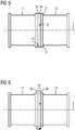
- FIG. 5 shows, by way of example, a variant embodiment of a flanging of the first and second encapsulation housings 11, 12. It can be seen that the flange surfaces 5a, 5b, 5c, 5d of the subelements 3a, 4a have the same dimensions as the flange surfaces of the interface openings of the first and second encapsulation housings 11 , 12 are limiting flanges. Thus, an aligned in the axial direction 2 congruent flange connection is formed. The circular path, on which the individual bracing elements are arranged, is the same in all flange surfaces. This is indicated by the dotted lines 17.
- each of the sub-elements 3, 3a, 4, 4a is individually flangeable in the respectively associated encapsulation housing 11, 12 and beyond the encapsulation housing 11, 12 with the interposition of the disk-shaped insulation arrangement 1, 1a are flanged.
- FIG. 5 Furthermore, the shell-side access from radial directions to the switching devices, which were designed here as a rotatable shaft 16, recognizable. It shows the FIG. 5 in that the shafts 16 arranged in the sub-elements 3a, 4a are offset relative to one another in the circumferential direction. Accordingly, in the FIG. 4 due to the location of the cutting plane only positions of the rotatable shafts 16 of the first sub-element 3a can be seen.
- Such a construction has the advantage that, if necessary, the receiving space of the first encapsulating housing 11 or the receiving space of the second encapsulating housing 12 can be connected to the cavity / joint gap in the interior of the disk-shaped insulation arrangement 1a. If necessary, by opening the switchable fluid channels both in the first sub-element 3a and in the second sub-element 4a and a communication of the receiving spaces of the first encapsulating 11 and the second encapsulating 12 are allowed.
- FIG. 6 shows an alternative embodiment possibility of a flange, wherein the local insulation arrangement 1b has a relation to the flanges surrounding the interface opening enlarged cross-section.
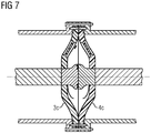
- FIG. 7 shows a training of FIG. 3 known device. Deviating an alternative flange connection is used.
- the flanges each have an outer shell side circumferential annular shoulder.
- sub-elements 3c, 4c are flush inserted in one of the flanges.
- Mantle surfaces of the sub-elements 3c, 4c are encompassed and covered by the annular shoulder.
- a screw connection is provided in the axial direction with the respective flange.
- the sub-elements are mechanically protected in an improved manner.
Landscapes
- Chemical & Material Sciences (AREA)
- Oil, Petroleum & Natural Gas (AREA)
- Gas-Insulated Switchgears (AREA)
- Driving Mechanisms And Operating Circuits Of Arc-Extinguishing High-Tension Switches (AREA)
- Installation Of Bus-Bars (AREA)
- Connector Housings Or Holding Contact Members (AREA)
Description
- Die Erfindung betrifft ein Isolationssystem mit einer elektrisch isolierenden im Wesentlichen scheibenförmigen Isolationsanordnung, welche eine Grundfläche überspannt, wobei die Isolationsanordnung zumindest ein erstes und ein zweites Teilelement aufweist, zwischen denen ein Fügespalt angeordnet ist, welcher die Grundfläche überspannt. Des Weiteren betrifft die Erfindung ein Montageverfahren eines Isolationssystems, welches eine im Wesentlichen scheibenförmige eine Ebene überspannende elektrisch isolierende Isolationsanordnung aufweist.
- Aus der Offenlegungsschrift
DE 10 2004 056 160 A1 ist ein Isolationssystem bekannt, welches eine elektrisch isolierende Isolationsanordnung aufweist. Die elektrisch isolierende Isolationsanordnung ist im Wesentlichen scheibenförmig ausgearbeitet, wobei die Isolationsanordnung eine Grundfläche überspannt. Die dortige Isolationsanordnung ist dabei im Wesentlichen einstückig ausgeformt, so dass die Anzahl von Dichtflächen bzw. Fügespalten innerhalb der Isolationsanordnung reduziert ist. Somit ergibt sich zum einen ein winkelsteifes Isolationssystem, welches zuverlässig elektrischen Isolationszwecken dient. Andererseits ist die Variabilität eines derartigen Isolationssystems als begrenzt einzuschätzen. Des Weiteren erweist es sich als aufwändig, das bekannte Isolationssystem zu montieren und beispielsweise in einer gasisolierten Schaltanlage einzusetzen. - Aus der Europäischen Patentanmeldung
EP 0 597 147 A1 geht eine gekapselte gasisolierte Hochspannungsanlage hervor, welche eine scheibenförmige Isolationsanordnung aufweist, die eine Grundfläche überspannt. Zwischen den Teilelementen erstreckt sich ein Fügespalt. Bei dem bekannten Isolationssystem wird eine Vielzahl von Dichtungen verwandt, um jedes der Teilelemente für sich als fluiddichte Barriere nutzen zu können. Entsprechend entstehen mehrere voneinander separierte Teilvolumina, welche voneinander separiert sind und entsprechend separat zu betreiben sind. Das DokumentEP 0 593 344 A1 beschreibt ein Isolationssystem, bei welchem zwischen einem ersten und einem zweiten Teilelement ein Fügespalt angeordnet ist. Über eine Ausnehmung in einem Teilelement ist der Fügespalt dauerhaft mit einem benachbarten Fluidvolumen verbunden. - Folglich ergibt sich als Aufgabe der Erfindung ein Isolationssystem zu schaffen, welches bei vorteilhaften Isolationseigenschaften variabler zu verwenden ist und ein vereinfachtes Montieren ermöglicht.
- Erfindungsgemäß wird diese Aufgabe bei einem Isolationssystem der eingangs genannten Art dadurch gelöst, dass der Fügespalt über einen schaltbaren Fluidkanal mit einem benachbarten Fluidvolumen verbindbar ist.
- Ein Isolationssystem dient einem elektrisch isolierten Halten eines Elementes bzw. einem Beabstanden von Elementen, die unterschiedliche elektrische Potentiale aufweisen können. So kann das Isolationssystem beispielsweise dazu dienen, einen Phasenleiter, welcher beispielsweise Hochspannungspotential führt, gegenüber einem beispielsweise Erdpotential führenden Tragelement, an welchem der Phasenleiter beispielsweise abgestützt ist, elektrisch isoliert zu positionieren. Eine scheibenförmige Isolationsanordnung kann bevorzugt von zumindest einem Phasenleiter durchsetzt sein. Ein Durchsetzen sollte die Grundfläche querend erfolgen. Der Phasenleiter kann fluiddicht in die Isolationsanordnung bzw. in zumindest eines der Teilelemente eingebettet sein. Insbesondere bei Nutzung einer scheibenförmigen Isolationsanordnung ist das Isolationssystem geeignet, beispielsweise über einer Öffnung (Grundfläche) nach Art einer Membran ein Verdämmen derselben zu bewirken, so dass die Öffnung durch das Isolationssystem im Wesentlichen geschlossen. Insbesondere kann ein Ein- bzw. Austritt von z.B. Fluiden durch die Öffnung verhindert sein. In der Öffnung kann sich beispielsweise eine Ebene erstrecken. Die Öffnung kann beispielsweise an einem Rohr bzw. Rohrstutzen liegen. Dabei kann die scheibenförmige Isolationsanordnung sowohl stirnseitig eine Öffnung am Rohr/Rohrstutzen überspannen oder auch eine Verdämmung innerhalb der Rohrausnehmung bewirken. Eine Grundfläche kann eben verlaufen oder beispielsweise auch gekrümmt verlaufen. Dabei kann das Isolationssystem eine fluiddichte Barriere darstellen. Insbesondere sollte die scheibenförmige Isolationsanordnung fluiddicht ausgeführt sein. Bevorzugt sollte das Isolationssystem eine Ausnehmung/Öffnung fluiddicht verschließen. Bevorzugt sollte dabei vorgesehen sein, dass die Isolationsanordnung ein erstes sowie ein zweites Teilelement aufweist. Darüber hinaus kann die Isolationsanordnung auch noch weitere Teilelemente aufweisen. Bevorzugt sollten sowohl das erste als auch das zweite Teilelement elektrisch isolierende Eigenschaften aufweisen, so dass jedes Teilelement für sich auch einer Potentialtrennung, beispielsweise eines Phasenleiters gegenüber einer stützenden Vorrichtung/einem Tragelement, die/das beispielsweise eine durch das Isolationssystem zu verschließende Öffnung aufweist, sicherstellt. Zwischen den beiden Teilelementen sollte bevorzugt ein Fügespalt ausgebildet sein, so dass jedes der beiden Teilelemente für sich, unabhängig vom jeweils anderen Teilelement, scheibenförmig eine Grundfläche überspannt. Somit besteht die Möglichkeit, dass jedes Teilelement unabhängig vom jeweils anderen Teilelement einem Verschließen einer Öffnung dient. Durch ein Zusammenfügen der Isolationsanordnung aus einem ersten und einem zweiten Teilelement besteht die Möglichkeit, die Formgebung der Isolationsanordnung abzuwandeln. So kann beispielsweise vorgesehen sein, dass die beiden Teilelemente identisch ausgeformt sind und einander in ihrer mechanischen Stabilisierung unterstützen. Es kann jedoch auch vorgesehen sein, dass die beiden Teilelemente abweichend voneinander ausgestaltet sind. Somit kann beispielsweise eine baukastenartige Zusammenstellung der Isolationsanordnung vorgenommen werden. Je nach Bedarf können so beispielsweise Teilelemente mit besonderen Oberflächenstrukturen, beispielsweise mit einer Verrippung oder einer besonderen Oberflächengüte kombiniert werden. So besteht beispielsweise die Möglichkeit, die Isolationsanordnung derart einzusetzen, dass das erste Teilelement, beispielsweise einem ersten Medium ausgesetzt ist und das zweite Teilelement einem zweiten Medium ausgesetzt ist. Dabei können das erste und das zweite Medium auch gleichartig sein. Es kann jedoch auch vorgesehen sein, dass die Medien voneinander abweichen. Entsprechend können die Medien z. B. unterschiedliche Aggressivitäten aufweisen. So besteht die Möglichkeit, jedes der Teilelemente auf das auf sie einwirkende Medium ausgerichtet auszulegen. So können beispielsweise aggressive Zerfallsprodukte an einem Teilelement angreifen, wohingegen am anderen Teilelement beispielsweise eine besondere Oberflächengüte vonnöten sein kann, um ein Anhaften des dortigen Mediums zu verhindern.
- Weiterhin besteht durch die Verwendung von Teilelementen an der Isolationsanordnung die Möglichkeit, zunächst jedes der Teilelemente für sich zu montieren und in einem späteren Schritt diese Teilelemente im bereits teilmontierten Zustand zu einem Isolationssystem zusammenzufügen. Dadurch kann eine Montage erleichtert werden, da beispielsweise Hilfskonstruktionen während der Montage nicht von Nöten sind und jedes der Teilelemente unmittelbar vormontiert bzw. verschiedenen Baugruppen zugeordnet werden kann. Die Isolationsanordnung des Isolationssystems kann eine fluiddichte Barriere darstellen. Dabei können die Teilelemente Bestandteile verschiedener fluiddichter Barrieren sein. Somit ist es beispielsweise möglich, einen Aufnahmeraum für ein Fluid zu verschließen und mit einem Fluid vorzubefüllen. Entsprechend können verschiedene vorbefüllte Bausteine unter Vervollständigung der Isolationsanordnung zusammengesetzt werden. Im Servicefall kann vorgesehen sein, dass eine Auftrennung der Isolationsanordnung vorgenommen wird. Die fluiddichte Barriere kann an zumindest einem der Aufnahmeräume aufrecht erhalten werden. Die Teilelemente können dabei beispielsweise gleichartig ausgeformt sein. Bei einer asymmetrischen Formgebung können die Teilelemente bevorzugt gegensinnig zueinander ausgerichtet sein, so dass im Zusammenspiel im Isolationssystem eine gegensinnige Lage von erstem und zweiten Teilelement erfolgt.
- Die Isolationsanordnung kann dabei von einem Phasenleiter, welcher dem Führen eines elektrischen Stromes bzw. einem Beaufschlagen mit erhöhter Spannung ausgesetzt ist, durchsetzt sein. Dabei kann jedes Teilelement für sich jeweils von dem Phasenleiter durchsetzt sein. Insbesondere kann jedes der Teilelemente den Phasenleiter vollständig umgreifen. Der Phasenleiter kann in unterschiedliche Abschnitte unterteilt sein. Der Phasenleiter kann in jedes der Teilelemente fluiddicht eingebettet sein. Es kann auch vorgesehen sein, dass mehrere Phasenleiter ein und dasselbe Teilelement bzw. die Isolationsanordnung durchsetzen. Ein Teilelement bzw. die Isolationsanordnung kann eine fluiddichte Barriere darstellen.
- Die Verbindung der beiden Teilelemente kann zu einem Entstehen eines Fügespaltes zwischen den beiden Teilelementen führen. Der Fügespalt sollte analog zu der Isolationsanordnung eine Grundfläche überspannen. Dabei kann sich der Fügespalt im Wesentlichen in der Ebene erstrecken, welche von der Isolationsanordnung überspannt ist bzw. parallel zu dieser Ebene verschoben sein. Somit ist beispielsweise die Möglichkeit gegeben, dass die Isolationsanordnung im Zusammenspiel von erstem und zweitem Teilelement oder jedes Teilelement für sich eine Grundfläche nach Art einer Membran überspannt. So ist es beispielsweise möglich, eine Öffnung von einem oder beiden Teilelementen überspannen zu lassen. Somit besteht die Möglichkeit, mittels des Isolationssystems beispielsweise eine Flanschöffnung in einem Kapselungsgehäuse insbesondere fluiddicht zu verschließen. Durch einen fluiddichten Verschluss ist die Möglichkeit gegeben, einen Aufnahmeraum des Kapselungsgehäuses mit einem elektrisch isolierenden Fluid zu befüllen, welches durch das Kapselungsgehäuse von der Umgebung hermetisch abgeschlossen ist. Als Fluide eignen sich beispielsweise gasförmiges oder flüssiges Schwefelhexafluorid, Stickstoff, Kohlendioxid oder auch andere Fluide, wie Isolieröle oder Isolieresther. Besonders können diese elektrisch isolierenden Fluide unter Überdruck im Innern des Kapselungsgehäuses angeordnet sein, so dass sich deren elektrische Isolationsfestigkeit zusätzlich erhöht. Somit besteht die Möglichkeit, innerhalb des Aufnahmeraumes Phasenleiter anzuordnen, welche von dem elektrisch isolierenden Fluid umspült sind und den Phasenleiter zumindest abschnittsweise elektrisch isolieren. Durch die Anordnung des Fügespaltes über der überspannten Grundfläche ist weiterhin die Möglichkeit gegeben, den Fügespalt selbst von Dichtelementen freizuhalten. Der Fügespalt erstreckt sich vorteilhaft innerhalb der durch die beiden Teilelemente ausgebildeten Membran. Eine hermetische Barriere der Isolieranordnung, welche zum Aufrechterhalten eines hermetischen Verschlusses eines Kapselungsgehäuses notwendig ist, wird so durch den Fügespalt nicht verletzt. Insbesondere kann vorgesehen sein, dass jedes der Teilelemente für sich eine fluiddichte Barriere über einer Öffnung ausbilden kann, so dass der Fügespalt sich quer zu der überspannten Grundfläche durch die Isolationsanordnung erstreckt. So ist es beispielsweise möglich, Teilelemente nacheinander auszutauschen, wobei die Isolationsanordnung ihre Barrierewirkung z. B. durch Verbleib eines der Teilelemente zumindest teilweise aufrechterhalten kann. Der Fügespalt kann dabei verschiedenartig profiliert sein. Es kann vorgesehen sein, dass der Fügespalt zwischen parallelen Wandabschnitten der beiden Teilelemente begrenzt ist. Der Fügespalt kann beispielsweise einen ebenen Verlauf aufweisen. Es kann jedoch auch vorgesehen sein, dass der Fügespalt verschiedenartige räumliche Ausdehnungen aufweist.
- Dabei kann vorteilhaft vorgesehen sein, dass zwischen dem ersten und dem zweiten Teilelement eine, insbesondere fluiddicht abschließbare Kavität angeordnet ist.
- Eine Anordnung einer fluiddicht abschließbaren Kavität zwischen den Teilelementen gestattet es, die Kavität beispielsweise mit einem bevorzugten Isoliermedium, wie beispielsweise einem Druckgas oder einer Isolierflüssigkeit zu befüllen. Bevorzugt kann die Befüllung der Kavität mit einem Medium erfolgen, welches beispielsweise auch in einem Aufnahmeraum befindlich ist, welcher von dem Isolationssystem zumindest abschnittsweise begrenzt ist. Dadurch ist eine Möglichkeit gegeben, die Isolationsfestigkeit auch in den zwischen den Teilelementen befindlichen Fügespalt/der Kavität zu verbessern. So kann beispielsweise auch vorgesehen sein, dass der Fügespalt beispielsweise Teil eines hermetisch abgeschlossenen Aufnahmeraumes ist. Weiter kann die Kavität selbst einen abgeschlossenen Aufnahmeraum bilden, oder die Kavität kann über einen oder mehrere Kanäle mit einem oder mehreren weiteren Aufnahmeräumen kommunizierend, verbunden sein. Die Kavität kann sich innerhalb des Fügespaltes lediglich abschnittsweise erweitern. Beispielsweise kann der Fügespalt sich zwischen im Wesentlichen parallelen Wandflächen der Teilelemente erstrecken, wobei lediglich ein Teilbereich sich zur Bildung einer Kavität erweitert. Zur Bildung einer Kavität können die die Kavität begrenzenden Wandflächen verschieden von einer parallelen Lage sein. Zumindest eine, insbesondere zwei der Wandflächen können gekrümmt, insbesondere konkav gekrümmt, ausgeformt sein. Insbesondere können Wandflächen zur Bildung einer Kavität gegensinnig konkav ausgeformt sein.
- Die Verwendung eines Fluidkanals ermöglicht es, den Fügespalt, insbesondere wenn dieser eine Kavität aufweist, mit zumindest einem weiteren Aufnahmeraum zu verbinden. Der weitere Aufnahmeraum kann ein benachbartes Fluidvolumen begrenzen bzw. aufnehmen. Eine Schaltbarkeit des Fluidkanals gestattet es, den Zeitpunkt einer Kommunikation des Fügespaltes mit einem weiteren Aufnahmeraum variabel festzulegen und gegebenenfalls auch wieder aufzuheben. So kann beispielsweise der Fügespalt mit einem Fluidvolumen verbunden sein, welches hinsichtlich seiner Qualität überwacht wird. Sobald der Fügespalt an dieses überwachte Aufnahmevolumen angeschlossen ist, kann auch eine Überwachung des Zustandes des Fügespaltes bzw. des im Fügespalt befindlichen Fluids erfolgen. Der schaltbare Fluidkanal sollte dabei eine fluiddichte Barriere zumindest eines Teilelementes durchsetzen.
- Eine weitere vorteilhafte Ausgestaltung kann vorsehen, dass der schaltbare Fluidkanal eine, insbesondere aus radialer Richtung betätigbare Schalteinrichtung aufweist.
- Der schaltbare Fluidkanal kann durch eine Schalteinrichtung verdämmt werden, so dass der Fluidkanal blockiert ist und kein Fluid durch den Fluidkanal hindurchströmen kann. Vorteilhafterweise sollte eine Betätigung der Schalteinrichtung des Fluidkanals bevorzugt aus einer radialen Richtung erfolgen, wobei eine radiale Richtung eine Richtung ist, welche quer zur überspannten Grundfläche der scheibenförmigen Isolationsanordnung verläuft. Die axiale Richtung einer Isolationsanordnung ergibt sich aus einer Achse, welche eine fluiddichte Barriere der Isolationsanordnung durchstößt. Es kann vorgesehen sein, eine Schalteinrichtung für den Fluidkanal beispielsweise in eines oder in beide Teilelemente einzubetten, so dass mantelseitig am Umfang der scheibenförmigen Isolationsanordnung ein Betätigungselement für den schaltbaren Fluidkanal angeordnet ist. Zum Schalten des Fluidkanals eignen sich beispielsweise Ventile, die z. B. durch eine Drehbewegung geöffnet und geschlossen werden können.
- Eine weitere vorteilhafte Ausgestaltung kann vorsehen, dass zumindest eines der Teilelemente eine konkav ausgekehlte Wandungsfläche aufweist.
- Eine konkav ausgekehlte Wandfläche in einem der Teilelemente ermöglicht es, eine Wegstrecke entlang der Oberfläche eines Teilelementes zu vergrößern und/oder das Volumen des Fügespaltes zu vergrößern. Insbesondere können an beiden Teilelementen der Isolationsanordnung konkav ausgekehlte Wandungsflächen vorgesehen sein. Insbesondere sollten diese Auskehlungen an den beiden Teilelementen entgegengesetzt zueinander ausgerichtet angeordnet sein. Somit ist die Möglichkeit gegeben, größere Volumina von Fluiden in den Fügespalt einzulagern. Entsprechend wird eine dielektrische Stabilisierung des Fügespaltes bewirkt. Fertigungstoleranzen können durch eine derartige konkave Auskehlung weiterhin ausgeglichen werden, wobei die Isolationsfestigkeit des Isolationssystems erhalten bleibt.
- Eine weitere vorteilhafte Ausgestaltung kann vorsehen, dass zumindest eines der Teilelemente eine Sollbruchstelle aufweist.
- Eine Sollbruchstelle in einem der Teilelemente ermöglicht es, beispielsweise eine Druckentlastung in den Fügespalt hinein, insbesondere wenn der Fügespalt eine Kavität aufweist, zu ermöglichen. So kann beispielsweise vorgesehen sein, dass bei einem Überdruck und einem Zerbersten eines der Teilelemente unter dem Überdruck ein zusätzliches Volumen (im Fügespalt/ der Kavität) zur Aufnahme von Fluid zur Verfügung steht. Ein Verflüchtigen von in den Fügespalt einströmendem Fluid wird verhindert. Analog kann bei einem Auftreten eines Überdruckes im Fügespalt bzw. in der Kavität eine Druckentlastung über eine Sollbruchstelle in einem benachbarten Aufnahmeraum erfolgen. Die Sollbruchstelle kann beispielsweise durch eine zumindest bereichsweise reduzierte Wandstärke eines Teilelements realisiert werden. Beispielsweise können in einer Scheibenfläche eines Teilelementes der Isolationsanordnung Nuten oder sacklochartige Ausnehmungen vorgesehen sein, um die Wandstärke des Teilelementes zu reduzieren. Im Bereich der Sollbruchstelle weist die fluiddichte Barriere innerhalb eines Teilelementes eine mechanische Schwächung auf, so dass eine Zerstörung bevorzugt in diesem Bereich eingeleitet wird.
- Vorteilhafterweise kann weiter vorgesehen sein, dass zumindest eines der Teilelemente, insbesondere beide Teilelemente von einem Phasenleiter durchsetzt ist/sind.
- Die beiden Teilelemente bzw. die Isolationsanordnung weisen eine scheibenförmige Struktur auf. Eine Scheibe ist ein Element, welches quer zu einer Achse eine Barriere darstellt. Eine Scheibe ist beispielsweise ein im Wesentlichen rotationssymmetrisches Element, wobei eine axiale Richtung der Isolationsanordnung bzw. der Teilelement durch eine Rotationsachse definiert ist. Die axiale Richtung durchsetzt eine Scheibenfläche des Teilelementes. Eine Scheibe kann eine fluiddichte Barriere darstellen. Die Scheibe kann jedoch auch permanent oder vorübergehend Öffnungen aufweisen, durch welche ein Fluid strömen kann. Darüber hinaus können auch weitere rotationssymmetrische Formen für die Teilelemente bzw. die scheibenförmige Isolationsanordnung genutzt werden, wobei die Rotationsachse dabei die axiale Richtung definiert. Insbesondere kann die Isolationsanordnung eine ringförmig umlaufende Mantelfläche aufweisen, welche die axiale Richtung umgreift.
- Ein Phasenleiter dient einer Übertragung eines elektrischen Stromes zwischen zwei Punkten. Phasenleiter sind dazu mit einer Spannung zu beaufschlagen, welche einen elektrischen Strom treibt. Die Phasenleiter durchsetzen die Isolationsanordnung in axialer Richtung, d. h., der Phasenleiter ist zumindest in einem Abschnitt von der Isolationsanordnung umgriffen, so dass über die Isolationsanordnung eine Beabstandung des Phasenleiters zu weiteren Bauteilen, die ein abweichendes elektrisches Potentials führen, gewährleistet ist. Dabei kann der Phasenleiter in verschiedene Abschnitte unterteilt sein, wobei verschiedene Abschnitte jeweils das erste oder das zweite Teilelement durchsetzen.
- Weiterhin kann vorteilhaft vorgesehen sein, dass im Fügespalt zwischen den Teilelementen ein Fügespalt des Phasenleiters angeordnet ist.
- Ein Phasenleiter kann aus verschiedenen Abschnitten zusammengesetzt sein. Diese Abschnitte sind miteinander entsprechend elektrisch zu kontaktieren, um im Phasenleiter einen durchgängigen Strompfad in axialer Richtung vor sowie hinter dem Isolationssystem zu gewährleisten. Eine Verbindung von Abschnitten des Phasenleiters im Fügespalt weist den Vorteil auf, dass diese Unstetigkeitsstelle im Phasenleiter in einem separierten Raum angeordnet ist. Dort kann dieser zum einen mechanisch vor äußeren Eingriffen geschützt angeordnet sein. Zum anderen kann dieser Bereich auch einer besonderen elektrischen Isolation unterzogen werden. So ist ein fluiddichtes Einbetten des Phasenleiters in ein Teilelement in vereinfachter Weise möglich.
- Erfindungsgemäß ist bei einem Montageverfahren eines Isolationssystems, welches eine im Wesentlichen scheibenförmige, eine Grundfläche überspannende elektrisch isolierenden Isolationsanordnung aufweist, vorgesehen, dass
- mit einem ersten Teilelement zumindest teilweise eine Schnittstellenöffnung eines ersten Kapselungsgehäuses verschlossen wird,
- mit einem zweiten Teilelement zumindest teilweise eine Schnittstellenöffnung eines zweiten Kapselungsgehäuses verschlossen wird,
- die Schnittstellenöffnungen aufweisende Schnittstellen der beiden Kapselungsgehäuse miteinander verbunden werden,
- nach Verbindung der Kapselungsgehäuse ein Fluidkanal eröffnet wird, über welchen ein Fluid aus einem Aufnahmeraum eines der Kapselungsgehäuse in einen Fügespalt zwischen den Teilelementen strömt.
- Ein Kapselungsgehäuse ist ein Gehäuse, in welches eine Schnittstellenöffnung, beispielsweise in Form einer Flanschöffnung aufweist. Diese Schnittstellenöffnung ist von einem Isolationssystem zu überspannen. Wird nunmehr ein erstes Teilelement eingesetzt, um eine Schnittstellenöffnung zumindest teilweise an einem ersten Kapselungsgehäuse zu verschließen und wird ein zweites Teilelement genutzt, um zumindest teilweise eine Schnittstellenöffnung eines zweiten Kapselungsgehäuses zu verschließen, so ist das Isolationssystem dazu geeignet, zwei Öffnungen an zwei Kapselungsgehäusen zu verschließen, wobei jeder Aufnahmeraum, in welchem die jeweilige Schnittstellenöffnung des jeweiligen Kapselungsgehäuses mündet, von einem Teilelement der Isolationsanordnung verschlossen ist. Somit besteht auch vor einem Zusammenfügen des ersten und des zweiten Kapselungsgehäuses die Möglichkeit, Aufnahmeräume des ersten sowie des zweiten Kapselungsgehäuses bereits mit einem unter Überdruck stehenden Fluid zu befüllen. Somit können beispielsweise teilmontierte Kapselungsgehäuse hergestellt werden, welche zu einem späteren Zeitpunkt zusammengefügt werden. Durch ein Befüllen der Aufnahmeräume mit einem Fluid ist ein Verschmutzen derselben verhindert. Insbesondere bei einem Beaufschlagen eines Aufnahmeraumes eines Kapselungsgehäuses mit Überdruck ist eher ein Entweichen des unter Überdruck stehenden Fluids möglich, als ein Eindringen von Fremdkörpern in den Aufnahmeraum der Kapselungsgehäuse. Die befüllten Aufnahmeräume können bereits vor einer Auslieferung zu einem Montageort vorgeprüft werden.
- Beispielsweise kann die Dichtigkeit der fluiddichten Barriere geprüft werden oder auch eine Spannungsprüfung vorgenommen werden. Weiter kann während der Vormontage das jeweilige Teilelement genutzt werden, um beispielsweise einen Abschnitt des Phasenleiters zu positionieren.
- Zu einem späteren Zeitpunkt können dann die beiden Kapselungsgehäuse miteinander verbunden werden, so dass eine Komplettierung des Isolationssystemes erfolgt. Somit ist eine Möglichkeit gegeben, die beiden Kapselungsgehäuse miteinander zu verbinden, wobei über das Isolationssystem eine Separation bzw. Trennung von Aufnahmeräumen im ersten sowie im zweiten Kapselungsgehäuse gegeben sein kann. Beispielsweise kann nach einem Verbinden der beiden Kapselungsgehäuse eine Druckerhöhung in den Aufnahmeräumen der Kapselungsgehäuse vorgesehen sein.
- Vorteilhaft kann weiter vorgesehen sein, dass die die Schnittstellenöffnungen aufweisenden Schnittstellen der beiden Kapselungsgehäuse unter Zwischenlage der Teilelemente aufweisenden Isolationsanordnung miteinander verbunden werden.
- Bei Zwischenlage des Isolationssystems ist die Möglichkeit gegeben, zusätzliche Verspannkräfte auf das Isolationssystem aufzubringen. Das Isolationssystem kann nach einem Verbinden der Schnittstellen mit jeder der beiden Schnittstellen in Verbindung stehen. Somit kann auch eine verbesserte Verspannung der Teilelemente erzielt werden. Beispielsweise kann das Isolationssystem in ein Flanschverbund der Kapselungsgehäuse eingelegt sein. Als Flanschverbund können verschiedene Flanschformen zum Einsatz gelangen. So können beispielsweise ebene Ringflansche Verwendung finden. Weiter können auch Flansche mit einer (Ring-)Schulter eingesetzt werden. Durch die Schulter ist die Möglichkeit gegeben, die Isolationsanordnung außenmantelseitig zu schützen.
- Wird nach einer Verbindung der Kapselungsgehäuse ein Fluidkanal eröffnet, so kann der Fügespalt zwischen den beiden Teilelementen mit einem Fluid aus einem der Aufnahmeräume, welches durch den Fluidkanal hindurchströmt, befüllt werden. Somit ist der Fügespalt zwischen den Teilelementen mit einem der Aufnahmeräume verbunden und kann über diese überwacht werden. Weiterhin ist dadurch die Möglichkeit gegeben, dass über die Isolationsanordnung sowohl der Aufnahmeraum des ersten Kapselungsgehäuses als auch der Aufnahmeraum des zweiten Kapselungsgehäuses über den dazwischenliegenden Spalt miteinander in Verbindung stehen. Somit wird die dielektrische Stabilität der Isolationsanordnung im Verbund der beiden Kapselungsgehäuse stabilisiert.
- Weiterhin ermöglicht die Füllung des Fügespaltes nach einer Verbindung der Kapselungsgehäuse die Möglichkeit, in einfacher Weise den Fügespalt mittelbar über einen Aufnahmeraum zu befüllen. Nachträgliches Befüllen über separate Füllvorrichtungen etc. für den Fügespalt sind so vermieden.
- Eine weitere vorteilhafte Ausgestaltung kann vorsehen, dass ein Phasenleiter einen ersten Abschnitt und einen zweiten Abschnitt aufweist, wobei der erste Abschnitt das erste Teilelement durchsetzt und der zweite Abschnitt das zweite Teilelement durchsetzt und während/nach einem Zusammenfügen der Kapselungsgehäuse die Abschnitte einander elektrisch leitend verbunden werden.
- Ein Phasenleiter dient einer Übertragung einer elektrischen Energie. Durch eine Auftrennung eines Phasenleiters in einem ersten Abschnitt und einem zweiten Abschnitt ist die Möglichkeit gegeben, jedem der beiden Abschnitte einen der Teilelemente zuzuordnen und diesen in das jeweilige Teilelement einzubetten. Entsprechend kann bereits während einer Montage eines Teilelementes an einem der beiden Kapselungsgehäuse auch eine Positionierung des jeweils zugeordneten Abschnittes eines Phasenleiters vorgesehen sein. Indem man während bzw. nach dem Zusammenfügen der Kapselungsgehäuse die Abschnitte kontaktiert, wird ein durchgängiger Strompfad durch die Isolationsanordnung hindurch hergestellt. Bevorzugt kann eine Kontaktierung der Abschnitte durch ein Aufeinanderpressen bzw. Ineinanderstecken der Abschnitte vorgenommen werden. So kann eine dauerhaft elastische Verbindung zwischen den beiden Abschnitten hergestellt werden, die gegebenenfalls auch aufgrund thermischer Wirkungen auftretende Dimensionsänderungen ausgleichen kann.
- Dabei kann vorgesehen sein, dass beispielsweise ein einzelner Phasenleiter jeweils zentrisch in der scheibenförmigen Isolationsanordnung angeordnet ist. Es kann jedoch auch vorgesehen sein, dass mehrere Phasenleiter in ein und derselben Isolationsanordnung angeordnet sind, wobei diese die Isolationsanordnung unabhängig voneinander durchsetzen und über die Isolationsanordnung sowohl untereinander elektrisch isoliert positioniert sind, als auch gegenüber einer abstützenden Einheit wie ein Kapselungsgehäuse elektrisch isoliert abgestützt sind.
- Im Folgenden wird in einer Zeichnung ein Ausführungsbeispiel der Erfindung schematisch gezeigt und nachfolgend näher beschrieben. Dabei zeigt die
- Figur 1
- ein Isolationssystem, bei welchem auf die Nutzung eines erfindungsgemäßen schaltbaren Fluidkanales verzichtet ist, im unmontierten Zustand, die
- Figur 2
- einen Zwischenschritt während einer Montage des Isolationssystems, die
- Figur 3
- das Isolationssystem mit einem erfindungsgemäßen schaltbaren Fluidkanal im montierten Zustand, die
- Figur 4
- einen Schnitt durch eine Ausführungsvariante eines Isolationssystems im montierten Zustand, die
- Figur 5
- eine erste Außenansicht, die
- Figur 6
- eine zweite Außenansicht in alternativer Ausgestaltung und die
- Figur 7
- eine Nutzung des Isolationssystems, bei welchem auf die Nutzung eines erfindungsgemäßen schaltbaren Fluidkanales verzichtet ist, in einer alternativen Flanschverbindung.
- Die
Figur 1 zeigt ein Isolationssystem im unmontierten Zustand. Das Isolationssystem weist eine scheibenförmige Isolationsanordnung 1 auf. Die scheibenförmige Isolationsanordnung ist dabei im Wesentlichen rotationssymmetrisch ausgeformt, wobei die Rotationsachse eine Längsachse 2 definiert. Die Längsachse 2 durchstößt eine insbesondere ebene Grundfläche, insbesondere im Wesentlichen lotrecht, welche von der Isolationsanordnung 1 überspannt ist. Die scheibenförmige Isolationsanordnung 1 weist ein erstes Teilelement 3 sowie ein zweites Teilelement 4 auf. Die beiden Teilelemente 3, 4 sind elektrisch isolierende Feststoffisolatoren. Die beiden Teilelemente 3, 4 sind annähernd gleichartig ausgeformt, wobei die beiden Teilelemente 3, 4 koaxial zueinander und zur Längsachse 2 liegen. Die Teilelemente 3, 4 weisen dabei eine im Wesentlichen kreisförmige Außenkontur auf, so dass eine außenseitige Zylindermantelfläche gebildet ist. Vorliegend wird auf ein Verwenden eines die Teilelemente 3, 4 außenmantelseitig umgreifenden zusätzlichen Rahmenelementes verzichtet. Ein derartiges Rahmenelement kann von Vorteil sein, um die beiden Teilelemente 3, 4 vor mechanischen Beanspruchungen zu schützen. Die Funktion des Rahmenelementes kann beispielsweise in einen Flansch bzw. in ein Gehäuse integriert sein (vgl.Fig. 7 ). Jedes der beiden Teilelemente 3, 4 weist an seinem äußeren Umfang jeweils ringförmige Flanschflächen 5a, 5b, 5c, 5d auf. Diese Flanschflächen 5a, 5b, 5c, 5d könnten beispielsweise auch in ein die beiden Teilelemente 3, 4 jeweils umgebendes Rahmenelement integriert sein, so dass Flanschkräfte von den beiden Teilelementen 3, 4 ferngehalten werden. Ein derartiges Rahmenelement kann beispielsweise ein metallischer Rahmen sein. Die Flanschflächen 5a, 5b, 5c, 5d sind ringförmig ausgebildet und laufen koaxial zur Längsachse 2 an den beiden Teilelementen 3, 4 um. In den Flanschflächen 5a, 5b, 5c, 5d liegen Durchgangsöffnungen 6, mittels welcher ein Verbolzen der beiden Teilelemente 3, 4 untereinander und gegenüber weiteren Flanschflächen ermöglicht ist. Weiter sind in den Flanschflächen 5a, 5c, 5d ringförmige Nuten 7 eingebracht, in welche beispielsweise Dichtelemente z. B. O-Ringe eingelegt werden können, so dass ein fluiddichter Verbund zwischen den Flanschflächen 5a, 5c, 5d und einer jeweils gegengleich anliegenden Flanschfläche ermöglicht ist. Zentrisch sind die beiden Teilelement 3, 4 von einem Phasenleiter durchsetzt, der in einen ersten Abschnitt 8a sowie einen zweiten Abschnitt 8b unterteilt ist. Die beiden Abschnitte 8a, 8b des Phasenleiters durchsetzen das erste bzw. das zweite Teilelement 3, 4 fluiddicht. Beispielhaft ist hier eine Durchführung mit einem einzigen zentrisch angeordneten Phasenleiter gezeigt. Es kann jedoch auch vorgesehen sein, dass mehrere Phasenleiter in jedem der beiden Teilelemente 3, 4 der scheibenförmigen Isolationsanordnung eingebettet sind. Jedes der beiden Teilelemente 3, 4 ist dabei mit einer Wölbung versehen, so dass die durch die jeweiligen Flanschflächen 5a, 5b, 5c, 5d gebildeten Flanschebenen von dem Wandungen des ersten bzw. zweiten Teilelementes 3, 4 durchbrochen sind. Somit entsteht jeweils ein ausgebauchtes erstes und zweites Teilelement 3, 4, wobei die einander zugewandten Seiten von erstem und zweitem Teilelement 3, 4 gegensinnig konkav ausgekehlte Wandungsflächen aufweisen, so dass ein zwischen den beiden Teilelementen 3, 4 nach einem Verspannen derselben gebildeter Fügespalt 9 eine sich erweiternde Kavität aufweist. - Die beiden Abschnitte 8a, 8b des Phasenleiters durchsetzen jeweils konkav liegende Wandungsflächen und ragen bis in die Ebene einer Flanschfläche 5b, 5c hinein. Zumindest in einem der beiden Abschnitte 8a, 8b des Phasenleiters sind Ausnehmungen 10 zur Aufnahme von federelastischen Kontaktelementen angeordnet. Eine oder mehrere Ausnehmungen 10 können jeweils nur in einem der beiden Abschnitte 8a, 8b des Phasenleiters angeordnet sein. Es kann jedoch auch vorgesehen sein, dass zumindest in einem der beiden Abschnitten 8a, 8b des Phasenleiters eine oder mehrere Ausnehmungen 10 angeordnet sind. Auf der konkav ausgekehlten Seite in der jeweiligen Scheibenfläche schließen die Abschnitte 8a, 8b jeweils bündig mit einer Ebene einer Flanschfläche 5b, 5c ab.
- Die scheibenförmige Isolationsanordnung 1 des Isolationssystemes ist vorgesehen, um in eine Flanschverbindung zwischen einem ersten Kapselungsgehäuse 11 und einem zweiten Kapselungsgehäuse 12 eingefügt zu werden. Die beiden Kapselungsgehäuse 11, 12 sind in der
Figur 1 schematisiert dargestellt. Jedes der beiden Kapselungsgehäuse 11, 12 verfügt über eine Flanschfläche, die dimensionsgleich mit Flanschflächen 5a, 5d der beiden Teilelemente 3, 4 der Isolationsanordnung 1 in Anlage gebracht werden können. Die beiden Kapselungsgehäuse 11, 12 sind dabei bevorzugt als metallische Kapselungsgehäuse ausgebildet, die eine fluiddichte Barriere darstellen, um in ihrem jeweiligen im Innern eingeschlossenen Aufnahmeraum ein elektrisch isolierendes Fluid hermetisch gekapselt aufzunehmen. Dabei dient die scheibenförmige Isolationsanordnung jeweils einem Verschließen einer Schnittstellenöffnung jeweils einer Schnittstelle in dem ersten bzw. zweiten Kapselungsgehäuse 11, 12. - Die
Figur 2 zeigt einen Zwischenmontagezustand, bei welchem das erste Teilelement 3 winkelstarr mit dem ersten Kapselungsgehäuse 11 verbunden ist und das zweite Teilelement 4 winkelstarr mit dem zweiten Kapselungsgehäuse 12 verbunden ist. Dabei ist zu erkennen, dass die Durchgangsöffnungen 6 noch frei von Befestigungsmitteln gehalten sind. Zur jeweiligen Positionierung und Festlegung der Teilelemente 3, 4 an dem jeweiligen Flansch des jeweiligen Kapselungsgehäuses 11, 12 sind im Umlauf der Flanschflächen 5a, 5b, 5c, 5d versetzt weitere Ausnehmungen angeordnet, welche ein individuelles Befestigen des jeweiligen Teilelementes 3, 4 an dem jeweiligen Kapselungsgehäuse 11, 12 ermöglicht. So besteht die Möglichkeit, die Schnittstellenöffnungen der Kapselungsgehäuse 11, 12 zu verschließen und die Teilelemente 3, 4 örtlich zu fixieren. Über in den ringförmigen Nuten 7 eingelegte Dichtelemente kann eine entsprechende Dichtwirkung erzielt werden. Nunmehr besteht die Möglichkeit, die Aufnahmeräume für das elektrisch isolierende Fluid im Innern des ersten Kapselungsgehäuses 11 sowie des zweiten Kapselungsgehäuses 12 mit einem Fluid vorzubefüllen. Hierbei sei auch auf einen beispielshaft im ersten Teilelement 3 eingebrachter Kanal 13 hingewiesen. Der Kanal 13 stellt eine dauerhafte Durchbrechung des ersten Teilelementes 3 dar, das sich in diesem Falle ein Befüllen des Aufnahmeraumes des ersten Kapselungsgehäuses 11 nicht anbietet, da ohne Verschluss des Kanals 13 ein Verflüchtigen von im Aufnahmeraum des ersten Kapselungsgehäuses 11 befindlichem Fluid über den Kanal 13 erfolgen kann. Die Position des Kanals 13 soll hier lediglich beispielhaft eine weitere Ausgestaltungsmöglichkeit angeben, wobei auch weitere Teilelemente oder weitere Ausführungen bedarfsweise mit einem derartigen dauerhaft durchlässigen Kanal 13 ausgestattet sein können. - Neben einem (zumindest teilweisen) Verschließen der Aufnahmeräume 11, 13 über das erste bzw. das zweite Teilelement 3, 4 weist eine derartige Montage den Vorteil auf, dass der Phasenleiter mit seinen Abschnitten 8a, 8b gegenüber dem jeweiligen Kapselungsgehäuse 11, 12 bereits positioniert ist. Somit ist ein hilfsweises Abstützen des Phasenleiters nicht notwendig. Weiterhin ist der Phasenleiter im Innern der Kapselungsgehäuse 11, 12 vor beispielsweise mechanischer Beeinflussung weitestgehend geschützt.
- In einem weiteren Montageschritt ist ein Verbolzen der die Schnittstellenöffnungen des ersten und zweiten Kapselungsgehäuses 11, 12 umgebenen Flansche unter Zwischenlage der Isolationsanordnung 1 (welche das erste und des zweite Teilelement 3, 4 aufweist) vorgesehen. Die in der
Figur 2 noch frei von jeglichem Verbindungselement gehaltenen Durchgangsöffnungen 6 sind nunmehr (Figur 3 ) von Bolzen durchsetzt, so dass zusätzlich zu der bereits erfolgten Verflanschung jedes einzelnen Teilelementes 3, 4 mit jeweils einem Kapselungsgehäuse 11, 12 ein gesamtes Verflanschen der Kapselungsgehäuse 11, 12 unter Zwischenlage der Teilelemente 3, 4 der scheibenförmigen Isolationsanordnung 1 gewährleistet ist. Nunmehr ist auch der sich einstellende Fügespalt 9 über ein in der entsprechenden ringförmigen Nut 7 eingelegtes Dichtelement abgedichtet. Der Fügespalt 9 erstreckt sich zentrisch beidseitig konvex gewölbt im Innern der Isolationsanordnung 1. Eine linsenförmige Kavität ist dabei über den Kanal 13 mit dem Aufnahmeraum des ersten Kapselungsgehäuses 11 verbunden. Das zweite Kapselungsgehäuse 12 bzw. dessen Aufnahmeraum ist vom Aufnahmeraum des ersten Kapselungsgehäuses 11 sowie von der Kavität im Innern der Isolationsanordnung 1 separiert. Die beiden Abschnitte 8a, 8b des Phasenleiters sind aufgrund der Verpressung der Kapselungsgehäuse 11, 12 und der Teilelemente 3, 4 gegeneinander gepresst, wobei im Bereich der Ausnehmungen 10 entsprechende Kontaktelemente zwischengelegt sind. Dies können beispielsweise Kontaktfedern oder Kontaktfinger sein, so dass ein stromtragfähiger Übergang zwischen den beiden Abschnitten 8a, 8b des Phasenleiters gegeben ist. Über diese Kontaktelemente können auch Wärmedehnungen kompensiert werden. Weiterhin ist in jedem der beiden Teilelemente 3, 4 eine Sollbruchstelle 14 angeordnet. Die Sollbruchstellen 14 sind in Form einer wandstärkereduzierten Zone ausgeformt, so dass bei einer zu großen Druckdifferenz zwischen den über die Isolationsanordnung 1 separierten Aufnahmeräumen bzw. zu der Kavität im Innern der Isolationsanordnung 1 durch Zerbersten der Barriere eines Teilelementes 3, 4 eine Entlastung auftritt. Beispielsweise kann bei einem Überdruck im Aufnahmeraum des zweiten Kapselungsgehäuses 12 eine Druckentlastung in die Kavität der scheibenförmigen Isolationsanordnung und über den Kanal 13 weiter folgend in den Aufnahmeraum des ersten Kapselungsgehäuses 11 erfolgen. Analog kann auch bei einem Auftreten eines Überdruckes in der Kavität eine Druckentlastung in einen der Aufnahmeräume durch ein Bersten einer Sollbruchstelle 14 erfolgen. - Als Alternative zur Verwendung eines Kanals 13 in einem der Teilelemente 3, 4 (oder beiden Teilelementen 3, 4) ist in der
Figur 4 abweichend die Verwendung eines schaltbaren Fluidkanals 15 vorgesehen. In einem der Teilelemente 3a der alternativ ausgeführten scheibenförmigen Isolationsanordnung 1a nachFigur 4 ist eine sich axial zur Längsachse 2 erstreckende Durchgangsöffnung angeordnet. Diese Durchgangsöffnung ist im Bereich von Flanschflächen 5a, 5b des entsprechenden Teilelementes 3a, 4a vorgesehen. Dabei sind am ersten Teilelement 3a im Schnitt zwei schaltbare Fluidkanale 15 dargestellt, so dass der zum Überströmen von Fluid aus einem Aufnahmeraum des ersten Kapselungsgehäuses 11 zur Verfügung stehende Querschnitt vergrößert ist. Zum Schalten der schaltbaren Fluidkanäle 15 ist jeweils eine drehbare Welle 16 vorgesehen, die aus radialer Richtung bezüglich der Längsachse 2 den Randbereich mit den Flanschflächen 5a, 5b, 5c, 5d des ersten Teilelements 3a durchsetzt. Die drehbaren Wellen 16 ragen jeweils in einen schaltbaren Fluidkanal 15 hinein und sind in dem Abschnitt, in welchen die drehbaren Wellen den jeweiligen schaltbaren Fluidkanal 15 passieren mit einer radial zur Drehachse der drehbaren Wellen 16 liegenden Durchgangsbohrung versehen. Diese Durchgangsbohrung weist in etwa den Querschnitt des zu schaltenden Fluidkanals 15 auf. Durch eine 90° Drehung ist es möglich, den jeweiligen schaltbaren Fluidkanal 15 freizugeben (sieheFig. 4 ). Bei weiterer Drehung um 90° wird der jeweilige schaltbare Fluidkanal 15 von den Mantelflächen der jeweiligen Welle 16 gesperrt. - In der
Figur 4 sind die bereits geöffneten schaltbare Fluidkanäle 15 erkennbar. Die Nutzung eines schaltbaren Fluidkanals 15 weist den Vorteil auf, dass während einer Verbindung der beiden Teilelemente 3a, 4a mit einem Flansch der jeweiligen Schnittstellenöffnung des ersten bzw. zweiten Kapselungsgehäuses 11, 12 jeweils ein fluiddichter Verschluss der jeweiligen Schnittstellenöffnung ermöglicht ist. Entsprechend können die Aufnahmeräume sowohl des ersten als auch des zweiten Kapselungsgehäuses 11, 12 mit einem Fluid vorbefüllt werden. Nach erfolgter Verflanschung des ersten und des zweiten Kapselungsgehäuse 11, 12 kann durch ein Öffnen der durch die drehbaren Wellen 16 gebildeten Ventile in den schaltbaren Fluidkanälen 15 ein Überströmen eines Fluides von dem Aufnahmeraum des ersten Kapselungsgehäuses 11 in die Kavität/den Fügespalt 9 zwischen den Teilelementen 3a, 4a der scheibenförmigen Isolationsanordnung 1a erfolgen. Entsprechend ist auch die Kavität mit einem gegebenenfalls unter Überdruck stehenden Fluid befüllt. - In der
Figur 4 ist die Schnittebene derart gewählt, das Ausnehmungen zur Aufnahme von Bolzen zum Verflanschen der einzelnen Teilelemente gerade nicht geschnitten sind, um einen Schnitt durch die drehbaren Wellen 16 abbilden zu können. - Die
Figur 5 zeigt beispielhaft eine Ausbildungsvariante einer Verflanschung des ersten sowie des zweiten Kapselungsgehäuses 11, 12. Dabei ist erkennbar, dass die Flanschflächen 5a, 5b, 5c, 5d der Teilelemente 3a, 4a dimensionsgleich mit den Flanschflächen der die Schnittstellenöffnungen des ersten bzw. des zweiten Kapselungsgehäuses 11, 12 begrenzenden Flansche sind. Somit ist eine in Achsrichtung 2 fluchtende deckungsgleiche Flanschverbindung gebildet. Die Kreisbahn, auf welcher die einzelnen Verspannelemente angeordnet sind, ist dabei in allen Flanschflächen gleich. Dies ist durch die strichpunktierten Linien 17 angedeutet. Lediglich in Umfangsrichtung liegt ein Versatz der einzelnen Verspannelemente vor, so dass jedes der Teilelemente 3, 3a, 4, 4a individuell in dem jeweils zugehörigen Kapselungsgehäuse 11, 12 verflanschbar ist und darüber hinaus die Kapselungsgehäuse 11, 12 unter Zwischenlage der scheibenförmigen Isolationsanordnung 1, 1a verflanschbar sind. - In der
Figur 5 ist weiterhin der mantelseitige Zugang aus radialen Richtungen zu den Schalteinrichtungen, welche hier als drehbare Welle 16 ausgeführt wurden, erkennbar. Dabei zeigt dieFigur 5 , dass in Umfangsrichtung die in den Teilelementen 3a, 4a angeordneten Wellen 16 versetzt zueinander sind. Entsprechend sind in derFigur 4 aufgrund der Lage der Schnittebene lediglich Positionen der drehbaren Wellen 16 des ersten Teilelementes 3a erkennbar. Eine derartige Konstruktion weist den Vorteil auf, dass bedarfsweise der Aufnahmeraum des ersten Kapselungsgehäuses 11 oder der Aufnahmeraum des zweiten Kapselungsgehäuses 12 mit der Kavität/dem Fügespalt im Innern der scheibenförmigen Isolationsanordnung 1a verbindbar ist. Bedarfsweise kann durch ein Öffnen der schaltbaren Fluidkanäle sowohl im ersten Teilelement 3a als auch im zweiten Teilelement 4a auch eine Kommunikation der Aufnahmeräume des ersten Kapselungsgehäuses 11 sowie des zweiten Kapselungsgehäuses 12 zugelassen werden. - Die
Figur 6 zeigt eine alternative Ausgestaltungsmöglichkeit einer Flanschverbindung, wobei die dortige Isolationsanordnung 1b einen gegenüber den die Schnittstellenöffnung umgebenden Flansche vergrößerten Querschnitt aufweist. Somit ist die Möglichkeit gegeben, einerseits jedes der Teilelemente 3b, 4b unabhängig mit einem Flansch des ersten oder des zweiten Kapselungsgehäuses 11, 12 zu verbinden und über den vergrößerten Teilkreis die beiden Teilelemente 3b, 4b miteinander zu verflanschen und so das erste sowie das zweite Kapselungsgehäuse 11, 12 winkelstarr zueinander festzulegen. In diesem Fall befindet sich eine Kreisbahn von Befestigungselementen in den Flanschflächen 5a, 5b, 5c, 5d des ersten bzw. zweiten Teilelementes 3b, 4b, um diese jeweils individuell mit dem ersten oder dem zweiten Kapselungsgehäuse 11, 12 zu verbinden. Weiterhin befindet sich in den Flanschflächen 5a, 5b, 5c, 5d eine weitere Kreisbahn, die einen vergrößerten Durchmesser aufweist, mittels welchen eine Zusammenfügung des ersten Teilelementes 3b sowie des zweiten Teilelementes 4b der scheibenförmigen Isolationsanordnung 1b ermöglicht ist, so dass auch das erste und das zweite Kapselungsgehäuse 11, 12 zueinander winkelstarr festgelegt sind. -
Figur 7 zeigt eine Fortbildung der ausFigur 3 bekannten Vorrichtung. Abweichend ist eine alternative Flanschverbindung genutzt. Die Flansche weisen jeweils eine außenmantelseitig umlaufende Ringschulter auf. So sind Teilelemente 3c, 4c bündig in einen der Flansche eingelegt. Mantelflächen der Teilelemente 3c, 4c sind von der Ringschulter umgriffen und überdeckt. Zur Befestigung der Teilelemente 3c, 4c ist eine Verschraubung in axialer Richtung mit dem jeweiligen Flansch vorgesehen. Somit sind die Teilelemente in verbesserter Weise mechanisch geschützt.
Claims (10)
- Isolationssystem mit einer elektrisch isolierenden, im Wesentlichen scheibenförmigen Isolationsanordnung (1, 1a, 1b), welche eine Grundfläche überspannt, wobei die Isolationsanordnung (1, 1a, 1b) zumindest ein erstes und ein zweites Teilelement (3, 3a, 3b, 3c, 4, 4a, 4b, 4c) aufweist, zwischen denen ein Fügespalt (9) angeordnet ist, welcher die Grundfläche überspannt,
dadurch gekennzeichnet, dass der Fügespalt (9) über einen schaltbaren Fluidkanal (15) mit einem benachbarten Fluidvolumen verbindbar ist. - Isolationssystem nach Anspruch 1,
dadurch gekennzeichnet, dass zwischen dem ersten und dem zweiten Teilelement (3, 3a, 3b, 3c, 4, 4a, 4b, 4c) eine, insbesondere fluiddicht abschließbare Kavität angeordnet ist. - Isolationssystem nach Anspruch 1 oder 2,
dadurch gekennzeichnet, d a s s der schaltbare Fluidkanal (15) eine insbesondere aus radialer Richtung betätigbare Schalteinrichtung (16) aufweist. - Isolationssystem nach einem der Ansprüche 1 bis 3,
dadurch gekennzeichnet, dass zumindest eines der Teilelemente (3, 3a, 3b, 3c, 4, 4a, 4b, 4c) eine konkav ausgekehlte Wandungsfläche aufweist. - Isolationssystem nach einem der Ansprüche 1 bis 4,
dadurch gekennzeichnet, dass zumindest eines der Teilelemente (3, 3a, 3b, 3c, 4, 4a, 4b, 4c) eine Sollbruchstelle (14) aufweist. - Isolationssystem nach einem der Ansprüche 1 bis 5,
dadurch gekennzeichnet, dass zumindest eines der Teilelemente (3, 3a, 3b, 3c, 4, 4a, 4b, 4c), insbesondere beide Teilelemente (3, 3a, 3b, 3c, 4, 4a, 4b, 4c) von einem Phasenleiter (8a, 8b) durchsetzt ist/sind. - Isolationssystem nach Anspruch 6,
dadurch gekennzeichnet, dass im Fügespalt (9) zwischen den Teilelementen (3, 3a, 3b, 3c, 4, 4a, 4b, 4c) ein Fügespalt (9) des Phasenleiters (8, 8a) angeordnet ist. - Montageverfahren eines Isolationssystems, welches eine im Wesentlichen scheibenförmige, eine Grundfläche überspannende elektrisch isolierende Isolationsanordnung (11a, 1b) aufweist,
dadurch gekennzeichnet, dass- mit einem ersten Teilelement (3, 3a, 3b, 3c) zumindest teilweise eine Schnittstellenöffnung eines ersten Kapselungsgehäuses (11) verschlossen wird,- mit einem zweiten Teilelement (4, 4a, 4b, 4c) zumindest teilweise eine Schnittstellenöffnung eines zweiten Kapselungsgehäuses (12) verschlossen wird,- die Schnittstellenöffnungen aufweisende Schnittstellen der beiden Kapselungsgehäuse (11, 12) miteinander verbunden werden,- nach Verbindung der Kapselungsgehäuse (11, 12) ein Fluidkanal (15) eröffnet wird, über welchen ein Fluid aus einem Aufnahmeraum eines der Kapselungsgehäuse (11, 12) in einen Fügespalt (9) zwischen den Teilelementen (3, 3a, 3b, 3c, 4, 4a, 4b, 4c) strömt. - Montageverfahren nach Anspruch 8,
dadurch gekennzeichnet, dass
die die Schnittstellenöffnungen aufweisenden Schnittstellen der beiden Kapselungsgehäuse (11, 12) unter Zwischenlage der die Teilelemente (3, 3a, 3b, 3c, 4, 4a, 4b, 4c) aufweisenden Isolationsanordnung (1, 1a, 1b) miteinander verbunden werden. - Montageverfahren nach einem der Ansprüche 8 oder 9,
dadurch gekennzeichnet, dass ein Phasenleiter einen ersten Abschnitt (8a) und einen zweiten Abschnitt (8b) aufweist, wobei der erste Abschnitt (8a) das erste Teilelement (3, 3a, 3b, 3c) durchsetzt und der zweite Abschnitt (8b) das zweite Teilelement (4, 4a, 4b, 4c) durchsetzt und während/nach einem Zusammenfügen der Kapselungsgehäuse (11, 12) die Abschnitte (8a, 8b) einander elektrisch leitend verbunden werden.
Applications Claiming Priority (2)
| Application Number | Priority Date | Filing Date | Title |
|---|---|---|---|
| DE102013211133.9A DE102013211133A1 (de) | 2013-06-14 | 2013-06-14 | Isolationssystem sowie Montageverfahren eines Isolationssystems |
| PCT/EP2014/061421 WO2014198581A1 (de) | 2013-06-14 | 2014-06-03 | Isolationssystem sowie montageverfahren eines isolationssystems |
Publications (2)
| Publication Number | Publication Date |
|---|---|
| EP2984718A1 EP2984718A1 (de) | 2016-02-17 |
| EP2984718B1 true EP2984718B1 (de) | 2017-11-01 |
Family
ID=50897586
Family Applications (1)
| Application Number | Title | Priority Date | Filing Date |
|---|---|---|---|
| EP14728913.6A Not-in-force EP2984718B1 (de) | 2013-06-14 | 2014-06-03 | Isolationssystem sowie montageverfahren eines isolationssystems |
Country Status (6)
| Country | Link |
|---|---|
| US (1) | US9991031B2 (de) |
| EP (1) | EP2984718B1 (de) |
| CN (1) | CN105324895B (de) |
| DE (1) | DE102013211133A1 (de) |
| RU (1) | RU2661912C2 (de) |
| WO (1) | WO2014198581A1 (de) |
Families Citing this family (9)
| Publication number | Priority date | Publication date | Assignee | Title |
|---|---|---|---|---|
| DE102015201678A1 (de) * | 2015-01-30 | 2016-08-04 | Siemens Aktiengesellschaft | Elektroenergieübertragungseinrichtung |
| EP3323180B1 (de) * | 2015-09-11 | 2020-12-16 | Siemens Aktiengesellschaft | Gasisoliertes elektrisches modul |
| DE102017210937A1 (de) * | 2017-06-28 | 2019-01-03 | Siemens Aktiengesellschaft | Isolieranordnung |
| DE102017210934A1 (de) * | 2017-06-28 | 2019-01-03 | Siemens Aktiengesellschaft | Isolatoranordnung sowie Montageverfahren zur Herstellung einer Isolatoranordnung |
| US10923891B2 (en) * | 2018-03-28 | 2021-02-16 | Eaton Intelligent Power Limited | Pressure relief mechanisms for gas insulated switchgear (GIS) housings and related GIS housings |
| EP3888206B1 (de) | 2018-11-27 | 2024-01-03 | Hitachi Energy Ltd | Isolator für eine gasisolierte mittel- oder hochspannungsschaltanlage |
| CN113130150B (zh) * | 2019-12-30 | 2022-07-12 | 西安西电高压开关有限责任公司 | Gis及其绝缘子 |
| DE102020128508A1 (de) * | 2020-10-29 | 2022-05-05 | TenneT TSO GmbH | Gasisolierte Hochspannungssteckverbindung, aufweisend eine druckführende Umschließung, wobei ein erster Teil der Umschließung eine Verbindungsbuchse und ein zweiter Teil der Umschließung einen Stecker ausbildet |
| CN113851286B (zh) * | 2021-08-12 | 2024-04-02 | 国网新疆电力有限公司电力科学研究院 | 实验用模块化高压绝缘套管 |
Family Cites Families (13)
| Publication number | Priority date | Publication date | Assignee | Title |
|---|---|---|---|---|
| DE1111690B (de) * | 1959-07-03 | 1961-07-27 | Telemecanique Electrique | Halterung fuer parallel nebeneinander angeordnete Sammelschienen in Verteileranlagen mittels eines kammartig geformten Isolierkoerpers |
| US3331911A (en) * | 1965-07-26 | 1967-07-18 | Westinghouse Electric Corp | Coaxial cable joint with a gas barrier |
| NL7316991A (nl) * | 1973-12-12 | 1975-06-16 | Nkf Kabel Bv | Uit starre segmenten opgebouwde met gas ge- vulde hoogspanningsleiding. |
| CH662452A5 (de) * | 1983-08-31 | 1987-09-30 | Bbc Brown Boveri & Cie | Metallgekapselte, gasisolierte hochspannungsleitung. |
| JPS6088466U (ja) * | 1983-11-24 | 1985-06-18 | 三菱電機株式会社 | 電力機器接続装置 |
| US5399095A (en) * | 1991-03-26 | 1995-03-21 | Square D Company | Variable phase positioning device |
| FR2696882B1 (fr) * | 1992-10-12 | 1994-12-09 | Alsthom Gec | Système de raccordement des enveloppes de deux appareils dont l'un au moins est sous pression. |
| ATE126406T1 (de) * | 1992-11-13 | 1995-08-15 | Gec Alsthom T & D Ag | Gekapselte gasisolierte hochspannungsanlage und baugruppe einer solchen anlage. |
| WO1997035371A1 (de) * | 1996-03-19 | 1997-09-25 | Siemens Aktiengesellschaft | Gasisolierte energieübertragungsanlage mit in abständen axial fixiertem innenleiter |
| JP4202075B2 (ja) | 2002-09-09 | 2008-12-24 | 中部電力株式会社 | ガス絶縁電気機器のスペーサ |
| DE102004006061A1 (de) | 2004-01-30 | 2005-08-18 | Siemens Ag | Hochspannungs-Freiluft-Durchführungsanordnung |
| DE102004056160A1 (de) | 2004-11-18 | 2006-05-24 | Siemens Ag | Scheibenisolator |
| DE102007046406A1 (de) * | 2007-09-24 | 2008-11-06 | Siemens Ag | Verbindungsverfahren für Kapselungsgehäuse und Anordnung mit mehreren Kapselungsgehäusen |
-
2013
- 2013-06-14 DE DE102013211133.9A patent/DE102013211133A1/de not_active Withdrawn
-
2014
- 2014-06-03 RU RU2016100721A patent/RU2661912C2/ru active
- 2014-06-03 WO PCT/EP2014/061421 patent/WO2014198581A1/de not_active Ceased
- 2014-06-03 CN CN201480033772.3A patent/CN105324895B/zh not_active Expired - Fee Related
- 2014-06-03 US US14/898,193 patent/US9991031B2/en active Active
- 2014-06-03 EP EP14728913.6A patent/EP2984718B1/de not_active Not-in-force
Non-Patent Citations (1)
| Title |
|---|
| None * |
Also Published As
| Publication number | Publication date |
|---|---|
| DE102013211133A1 (de) | 2014-12-18 |
| RU2016100721A (ru) | 2017-07-19 |
| EP2984718A1 (de) | 2016-02-17 |
| US20160133359A1 (en) | 2016-05-12 |
| US9991031B2 (en) | 2018-06-05 |
| WO2014198581A1 (de) | 2014-12-18 |
| CN105324895B (zh) | 2018-11-23 |
| CN105324895A (zh) | 2016-02-10 |
| RU2661912C2 (ru) | 2018-07-23 |
Similar Documents
| Publication | Publication Date | Title |
|---|---|---|
| EP2984718B1 (de) | Isolationssystem sowie montageverfahren eines isolationssystems | |
| DE60013673T2 (de) | Schaltanlage und Leistungsschalteranordnung | |
| EP2286495B1 (de) | Anordnung mit einem kapselungsgehäuse | |
| DE60037237T2 (de) | Verbindungssystem zwischen Mittel- oder Hochspannungszellen | |
| DE102011086663A1 (de) | Druckgasisolierte Elektroenergieübertragungseinrichtung | |
| EP3469672B1 (de) | Isolator | |
| EP2859629B1 (de) | Druckbehälteranordnung mit einem längenveränderlichen kompensationsabschnitt | |
| EP2630710B1 (de) | Mehrpolig gasisolierter sammelschienenabschnitt | |
| DE102012213339A1 (de) | Losflanschanordnung für eine Elektroenergieübertragungseinrichtung | |
| EP3048617B1 (de) | Überspannungsableiter | |
| EP3093938B1 (de) | Hochspannungs-durchführungssystem | |
| EP2283492B1 (de) | Anordnung mit einer gasdichten messdurchführung | |
| EP3082136B1 (de) | Gasisolierter überspannungsableiter | |
| EP2156444A1 (de) | Überspannungsableiteranordnung | |
| EP3254349B1 (de) | Verschlussbaugruppe mit einer wandung | |
| DE102015201678A1 (de) | Elektroenergieübertragungseinrichtung | |
| DE102017210934A1 (de) | Isolatoranordnung sowie Montageverfahren zur Herstellung einer Isolatoranordnung | |
| DE19959450B4 (de) | Elektrische Steckverbindung, welche sich während der Montage der isoliergasbefüllten Schaltanlagenkomponenten selbsttätig mit Isoliergas befüllt | |
| DE102019206737A1 (de) | Elektroenergieübertragungseinrichtung | |
| EP3235082B1 (de) | Kabeldurchführung für messleitungen in ein elektrisch isolierende flanschverschlussdeckel | |
| DE102015211481A1 (de) | Isolatoranordnung | |
| EP4687236A1 (de) | Schiebekompensator mit klemmring | |
| DE102008056478A1 (de) | Schaltgeräteanordnung mit einem Kapselungsgehäuse | |
| DE102017210937A1 (de) | Isolieranordnung | |
| DE102017201305A1 (de) | Fluidisolierte Elektroenergieübertragungseinrichtung |
Legal Events
| Date | Code | Title | Description |
|---|---|---|---|
| PUAI | Public reference made under article 153(3) epc to a published international application that has entered the european phase |
Free format text: ORIGINAL CODE: 0009012 |
|
| 17P | Request for examination filed |
Effective date: 20151112 |
|
| AK | Designated contracting states |
Kind code of ref document: A1 Designated state(s): AL AT BE BG CH CY CZ DE DK EE ES FI FR GB GR HR HU IE IS IT LI LT LU LV MC MK MT NL NO PL PT RO RS SE SI SK SM TR |
|
| AX | Request for extension of the european patent |
Extension state: BA ME |
|
| DAX | Request for extension of the european patent (deleted) | ||
| 17Q | First examination report despatched |
Effective date: 20170124 |
|
| GRAP | Despatch of communication of intention to grant a patent |
Free format text: ORIGINAL CODE: EPIDOSNIGR1 |
|
| INTG | Intention to grant announced |
Effective date: 20170531 |
|
| RAP1 | Party data changed (applicant data changed or rights of an application transferred) |
Owner name: SIEMENS AKTIENGESELLSCHAFT |
|
| GRAS | Grant fee paid |
Free format text: ORIGINAL CODE: EPIDOSNIGR3 |
|
| GRAA | (expected) grant |
Free format text: ORIGINAL CODE: 0009210 |
|
| AK | Designated contracting states |
Kind code of ref document: B1 Designated state(s): AL AT BE BG CH CY CZ DE DK EE ES FI FR GB GR HR HU IE IS IT LI LT LU LV MC MK MT NL NO PL PT RO RS SE SI SK SM TR |
|
| REG | Reference to a national code |
Ref country code: GB Ref legal event code: FG4D Free format text: NOT ENGLISH |
|
| REG | Reference to a national code |
Ref country code: CH Ref legal event code: EP Ref country code: AT Ref legal event code: REF Ref document number: 942939 Country of ref document: AT Kind code of ref document: T Effective date: 20171115 |
|
| REG | Reference to a national code |
Ref country code: IE Ref legal event code: FG4D Free format text: LANGUAGE OF EP DOCUMENT: GERMAN |
|
| REG | Reference to a national code |
Ref country code: CH Ref legal event code: NV Representative=s name: SIEMENS SCHWEIZ AG, CH |
|
| REG | Reference to a national code |
Ref country code: DE Ref legal event code: R096 Ref document number: 502014006058 Country of ref document: DE |
|
| REG | Reference to a national code |
Ref country code: NL Ref legal event code: MP Effective date: 20171101 |
|
| REG | Reference to a national code |
Ref country code: LT Ref legal event code: MG4D |
|
| PG25 | Lapsed in a contracting state [announced via postgrant information from national office to epo] |
Ref country code: LT Free format text: LAPSE BECAUSE OF FAILURE TO SUBMIT A TRANSLATION OF THE DESCRIPTION OR TO PAY THE FEE WITHIN THE PRESCRIBED TIME-LIMIT Effective date: 20171101 Ref country code: FI Free format text: LAPSE BECAUSE OF FAILURE TO SUBMIT A TRANSLATION OF THE DESCRIPTION OR TO PAY THE FEE WITHIN THE PRESCRIBED TIME-LIMIT Effective date: 20171101 Ref country code: SE Free format text: LAPSE BECAUSE OF FAILURE TO SUBMIT A TRANSLATION OF THE DESCRIPTION OR TO PAY THE FEE WITHIN THE PRESCRIBED TIME-LIMIT Effective date: 20171101 Ref country code: NO Free format text: LAPSE BECAUSE OF FAILURE TO SUBMIT A TRANSLATION OF THE DESCRIPTION OR TO PAY THE FEE WITHIN THE PRESCRIBED TIME-LIMIT Effective date: 20180201 Ref country code: ES Free format text: LAPSE BECAUSE OF FAILURE TO SUBMIT A TRANSLATION OF THE DESCRIPTION OR TO PAY THE FEE WITHIN THE PRESCRIBED TIME-LIMIT Effective date: 20171101 Ref country code: NL Free format text: LAPSE BECAUSE OF FAILURE TO SUBMIT A TRANSLATION OF THE DESCRIPTION OR TO PAY THE FEE WITHIN THE PRESCRIBED TIME-LIMIT Effective date: 20171101 |
|
| PG25 | Lapsed in a contracting state [announced via postgrant information from national office to epo] |
Ref country code: GR Free format text: LAPSE BECAUSE OF FAILURE TO SUBMIT A TRANSLATION OF THE DESCRIPTION OR TO PAY THE FEE WITHIN THE PRESCRIBED TIME-LIMIT Effective date: 20180202 Ref country code: IS Free format text: LAPSE BECAUSE OF FAILURE TO SUBMIT A TRANSLATION OF THE DESCRIPTION OR TO PAY THE FEE WITHIN THE PRESCRIBED TIME-LIMIT Effective date: 20180301 Ref country code: HR Free format text: LAPSE BECAUSE OF FAILURE TO SUBMIT A TRANSLATION OF THE DESCRIPTION OR TO PAY THE FEE WITHIN THE PRESCRIBED TIME-LIMIT Effective date: 20171101 Ref country code: LV Free format text: LAPSE BECAUSE OF FAILURE TO SUBMIT A TRANSLATION OF THE DESCRIPTION OR TO PAY THE FEE WITHIN THE PRESCRIBED TIME-LIMIT Effective date: 20171101 Ref country code: RS Free format text: LAPSE BECAUSE OF FAILURE TO SUBMIT A TRANSLATION OF THE DESCRIPTION OR TO PAY THE FEE WITHIN THE PRESCRIBED TIME-LIMIT Effective date: 20171101 Ref country code: BG Free format text: LAPSE BECAUSE OF FAILURE TO SUBMIT A TRANSLATION OF THE DESCRIPTION OR TO PAY THE FEE WITHIN THE PRESCRIBED TIME-LIMIT Effective date: 20180201 |
|
| REG | Reference to a national code |
Ref country code: FR Ref legal event code: PLFP Year of fee payment: 5 |
|
| PG25 | Lapsed in a contracting state [announced via postgrant information from national office to epo] |
Ref country code: EE Free format text: LAPSE BECAUSE OF FAILURE TO SUBMIT A TRANSLATION OF THE DESCRIPTION OR TO PAY THE FEE WITHIN THE PRESCRIBED TIME-LIMIT Effective date: 20171101 Ref country code: DK Free format text: LAPSE BECAUSE OF FAILURE TO SUBMIT A TRANSLATION OF THE DESCRIPTION OR TO PAY THE FEE WITHIN THE PRESCRIBED TIME-LIMIT Effective date: 20171101 Ref country code: CZ Free format text: LAPSE BECAUSE OF FAILURE TO SUBMIT A TRANSLATION OF THE DESCRIPTION OR TO PAY THE FEE WITHIN THE PRESCRIBED TIME-LIMIT Effective date: 20171101 Ref country code: CY Free format text: LAPSE BECAUSE OF FAILURE TO SUBMIT A TRANSLATION OF THE DESCRIPTION OR TO PAY THE FEE WITHIN THE PRESCRIBED TIME-LIMIT Effective date: 20171101 Ref country code: SK Free format text: LAPSE BECAUSE OF FAILURE TO SUBMIT A TRANSLATION OF THE DESCRIPTION OR TO PAY THE FEE WITHIN THE PRESCRIBED TIME-LIMIT Effective date: 20171101 |
|
| REG | Reference to a national code |
Ref country code: DE Ref legal event code: R097 Ref document number: 502014006058 Country of ref document: DE |
|
| PG25 | Lapsed in a contracting state [announced via postgrant information from national office to epo] |
Ref country code: PL Free format text: LAPSE BECAUSE OF FAILURE TO SUBMIT A TRANSLATION OF THE DESCRIPTION OR TO PAY THE FEE WITHIN THE PRESCRIBED TIME-LIMIT Effective date: 20171101 Ref country code: SM Free format text: LAPSE BECAUSE OF FAILURE TO SUBMIT A TRANSLATION OF THE DESCRIPTION OR TO PAY THE FEE WITHIN THE PRESCRIBED TIME-LIMIT Effective date: 20171101 Ref country code: RO Free format text: LAPSE BECAUSE OF FAILURE TO SUBMIT A TRANSLATION OF THE DESCRIPTION OR TO PAY THE FEE WITHIN THE PRESCRIBED TIME-LIMIT Effective date: 20171101 Ref country code: IT Free format text: LAPSE BECAUSE OF FAILURE TO SUBMIT A TRANSLATION OF THE DESCRIPTION OR TO PAY THE FEE WITHIN THE PRESCRIBED TIME-LIMIT Effective date: 20171101 |
|
| PLBE | No opposition filed within time limit |
Free format text: ORIGINAL CODE: 0009261 |
|
| STAA | Information on the status of an ep patent application or granted ep patent |
Free format text: STATUS: NO OPPOSITION FILED WITHIN TIME LIMIT |
|
| PG25 | Lapsed in a contracting state [announced via postgrant information from national office to epo] |
Ref country code: MT Free format text: LAPSE BECAUSE OF FAILURE TO SUBMIT A TRANSLATION OF THE DESCRIPTION OR TO PAY THE FEE WITHIN THE PRESCRIBED TIME-LIMIT Effective date: 20171101 |
|
| 26N | No opposition filed |
Effective date: 20180802 |
|
| PG25 | Lapsed in a contracting state [announced via postgrant information from national office to epo] |
Ref country code: SI Free format text: LAPSE BECAUSE OF FAILURE TO SUBMIT A TRANSLATION OF THE DESCRIPTION OR TO PAY THE FEE WITHIN THE PRESCRIBED TIME-LIMIT Effective date: 20171101 |
|
| REG | Reference to a national code |
Ref country code: BE Ref legal event code: MM Effective date: 20180630 |
|
| REG | Reference to a national code |
Ref country code: IE Ref legal event code: MM4A |
|
| PG25 | Lapsed in a contracting state [announced via postgrant information from national office to epo] |
Ref country code: MC Free format text: LAPSE BECAUSE OF FAILURE TO SUBMIT A TRANSLATION OF THE DESCRIPTION OR TO PAY THE FEE WITHIN THE PRESCRIBED TIME-LIMIT Effective date: 20171101 Ref country code: LU Free format text: LAPSE BECAUSE OF NON-PAYMENT OF DUE FEES Effective date: 20180603 |
|
| PG25 | Lapsed in a contracting state [announced via postgrant information from national office to epo] |
Ref country code: IE Free format text: LAPSE BECAUSE OF NON-PAYMENT OF DUE FEES Effective date: 20180603 |
|
| PG25 | Lapsed in a contracting state [announced via postgrant information from national office to epo] |
Ref country code: BE Free format text: LAPSE BECAUSE OF NON-PAYMENT OF DUE FEES Effective date: 20180630 |
|
| PG25 | Lapsed in a contracting state [announced via postgrant information from national office to epo] |
Ref country code: TR Free format text: LAPSE BECAUSE OF FAILURE TO SUBMIT A TRANSLATION OF THE DESCRIPTION OR TO PAY THE FEE WITHIN THE PRESCRIBED TIME-LIMIT Effective date: 20171101 |
|
| PG25 | Lapsed in a contracting state [announced via postgrant information from national office to epo] |
Ref country code: PT Free format text: LAPSE BECAUSE OF FAILURE TO SUBMIT A TRANSLATION OF THE DESCRIPTION OR TO PAY THE FEE WITHIN THE PRESCRIBED TIME-LIMIT Effective date: 20171101 |
|
| PG25 | Lapsed in a contracting state [announced via postgrant information from national office to epo] |
Ref country code: MK Free format text: LAPSE BECAUSE OF NON-PAYMENT OF DUE FEES Effective date: 20171101 Ref country code: HU Free format text: LAPSE BECAUSE OF FAILURE TO SUBMIT A TRANSLATION OF THE DESCRIPTION OR TO PAY THE FEE WITHIN THE PRESCRIBED TIME-LIMIT; INVALID AB INITIO Effective date: 20140603 |
|
| PG25 | Lapsed in a contracting state [announced via postgrant information from national office to epo] |
Ref country code: AL Free format text: LAPSE BECAUSE OF FAILURE TO SUBMIT A TRANSLATION OF THE DESCRIPTION OR TO PAY THE FEE WITHIN THE PRESCRIBED TIME-LIMIT Effective date: 20171101 |
|
| REG | Reference to a national code |
Ref country code: AT Ref legal event code: MM01 Ref document number: 942939 Country of ref document: AT Kind code of ref document: T Effective date: 20190603 |
|
| PG25 | Lapsed in a contracting state [announced via postgrant information from national office to epo] |
Ref country code: AT Free format text: LAPSE BECAUSE OF NON-PAYMENT OF DUE FEES Effective date: 20190603 |
|
| REG | Reference to a national code |
Ref country code: DE Ref legal event code: R081 Ref document number: 502014006058 Country of ref document: DE Owner name: SIEMENS ENERGY GLOBAL GMBH & CO. KG, DE Free format text: FORMER OWNER: SIEMENS AKTIENGESELLSCHAFT, 80333 MUENCHEN, DE |
|
| PGFP | Annual fee paid to national office [announced via postgrant information from national office to epo] |
Ref country code: FR Payment date: 20210621 Year of fee payment: 8 |
|
| PGFP | Annual fee paid to national office [announced via postgrant information from national office to epo] |
Ref country code: CH Payment date: 20210906 Year of fee payment: 8 |
|
| PGFP | Annual fee paid to national office [announced via postgrant information from national office to epo] |
Ref country code: DE Payment date: 20210819 Year of fee payment: 8 Ref country code: GB Payment date: 20210705 Year of fee payment: 8 |
|
| REG | Reference to a national code |
Ref country code: GB Ref legal event code: 732E Free format text: REGISTERED BETWEEN 20220901 AND 20220907 |
|
| REG | Reference to a national code |
Ref country code: DE Ref legal event code: R119 Ref document number: 502014006058 Country of ref document: DE |
|
| REG | Reference to a national code |
Ref country code: CH Ref legal event code: PL |
|
| GBPC | Gb: european patent ceased through non-payment of renewal fee |
Effective date: 20220603 |
|
| PG25 | Lapsed in a contracting state [announced via postgrant information from national office to epo] |
Ref country code: LI Free format text: LAPSE BECAUSE OF NON-PAYMENT OF DUE FEES Effective date: 20220630 Ref country code: FR Free format text: LAPSE BECAUSE OF NON-PAYMENT OF DUE FEES Effective date: 20220630 Ref country code: CH Free format text: LAPSE BECAUSE OF NON-PAYMENT OF DUE FEES Effective date: 20220630 |
|
| PG25 | Lapsed in a contracting state [announced via postgrant information from national office to epo] |
Ref country code: GB Free format text: LAPSE BECAUSE OF NON-PAYMENT OF DUE FEES Effective date: 20220603 Ref country code: DE Free format text: LAPSE BECAUSE OF NON-PAYMENT OF DUE FEES Effective date: 20230103 |