EP2985010A1 - Haltungskorrekturvorrichtung - Google Patents
Haltungskorrekturvorrichtung Download PDFInfo
- Publication number
- EP2985010A1 EP2985010A1 EP13881695.4A EP13881695A EP2985010A1 EP 2985010 A1 EP2985010 A1 EP 2985010A1 EP 13881695 A EP13881695 A EP 13881695A EP 2985010 A1 EP2985010 A1 EP 2985010A1
- Authority
- EP
- European Patent Office
- Prior art keywords
- thorax
- innominate
- pad
- compression part
- belt
- Prior art date
- Legal status (The legal status is an assumption and is not a legal conclusion. Google has not performed a legal analysis and makes no representation as to the accuracy of the status listed.)
- Withdrawn
Links
- 238000007906 compression Methods 0.000 claims abstract description 163
- 230000006835 compression Effects 0.000 claims abstract description 161
- 210000004197 pelvis Anatomy 0.000 claims abstract description 43
- 210000000038 chest Anatomy 0.000 claims description 148
- 238000004804 winding Methods 0.000 claims description 84
- 230000007246 mechanism Effects 0.000 claims description 70
- 238000003780 insertion Methods 0.000 claims description 17
- 230000037431 insertion Effects 0.000 claims description 17
- 230000003187 abdominal effect Effects 0.000 claims description 8
- 210000000988 bone and bone Anatomy 0.000 description 18
- 210000003131 sacroiliac joint Anatomy 0.000 description 18
- 239000000463 material Substances 0.000 description 12
- 208000002193 Pain Diseases 0.000 description 10
- 238000005452 bending Methods 0.000 description 9
- 238000006073 displacement reaction Methods 0.000 description 9
- 208000008930 Low Back Pain Diseases 0.000 description 8
- 238000000034 method Methods 0.000 description 7
- 239000000057 synthetic resin Substances 0.000 description 7
- 229920003002 synthetic resin Polymers 0.000 description 7
- 208000008035 Back Pain Diseases 0.000 description 6
- 230000000694 effects Effects 0.000 description 5
- 239000011521 glass Substances 0.000 description 4
- 210000001503 joint Anatomy 0.000 description 4
- 210000003205 muscle Anatomy 0.000 description 4
- 229920005989 resin Polymers 0.000 description 4
- 239000011347 resin Substances 0.000 description 4
- 229920003051 synthetic elastomer Polymers 0.000 description 4
- 239000005061 synthetic rubber Substances 0.000 description 4
- 210000000115 thoracic cavity Anatomy 0.000 description 4
- 229920001875 Ebonite Polymers 0.000 description 3
- XAGFODPZIPBFFR-UHFFFAOYSA-N aluminium Chemical compound [Al] XAGFODPZIPBFFR-UHFFFAOYSA-N 0.000 description 3
- 229910052782 aluminium Inorganic materials 0.000 description 3
- 210000002414 leg Anatomy 0.000 description 3
- 239000002023 wood Substances 0.000 description 3
- 210000004556 brain Anatomy 0.000 description 2
- 239000000835 fiber Substances 0.000 description 2
- 230000000452 restraining effect Effects 0.000 description 2
- 230000032683 aging Effects 0.000 description 1
- 238000010586 diagram Methods 0.000 description 1
- 201000010099 disease Diseases 0.000 description 1
- 208000037265 diseases, disorders, signs and symptoms Diseases 0.000 description 1
- 239000004744 fabric Substances 0.000 description 1
- 210000004394 hip joint Anatomy 0.000 description 1
- 238000009434 installation Methods 0.000 description 1
- 239000010985 leather Substances 0.000 description 1
- 210000004061 pubic symphysis Anatomy 0.000 description 1
- 230000029058 respiratory gaseous exchange Effects 0.000 description 1
- 238000005096 rolling process Methods 0.000 description 1
- 210000001562 sternum Anatomy 0.000 description 1
- 239000012209 synthetic fiber Substances 0.000 description 1
- 229920002994 synthetic fiber Polymers 0.000 description 1
- 235000013311 vegetables Nutrition 0.000 description 1
- 210000001835 viscera Anatomy 0.000 description 1
Images


Classifications
-
- A—HUMAN NECESSITIES
- A61—MEDICAL OR VETERINARY SCIENCE; HYGIENE
- A61F—FILTERS IMPLANTABLE INTO BLOOD VESSELS; PROSTHESES; DEVICES PROVIDING PATENCY TO, OR PREVENTING COLLAPSING OF, TUBULAR STRUCTURES OF THE BODY, e.g. STENTS; ORTHOPAEDIC, NURSING OR CONTRACEPTIVE DEVICES; FOMENTATION; TREATMENT OR PROTECTION OF EYES OR EARS; BANDAGES, DRESSINGS OR ABSORBENT PADS; FIRST-AID KITS
- A61F5/00—Orthopaedic methods or devices for non-surgical treatment of bones or joints; Nursing devices ; Anti-rape devices
- A61F5/01—Orthopaedic devices, e.g. long-term immobilising or pressure directing devices for treating broken or deformed bones such as splints, casts or braces
- A61F5/02—Orthopaedic corsets
- A61F5/028—Braces for providing support to the lower back, e.g. lumbo sacral supports
-
- A—HUMAN NECESSITIES
- A61—MEDICAL OR VETERINARY SCIENCE; HYGIENE
- A61F—FILTERS IMPLANTABLE INTO BLOOD VESSELS; PROSTHESES; DEVICES PROVIDING PATENCY TO, OR PREVENTING COLLAPSING OF, TUBULAR STRUCTURES OF THE BODY, e.g. STENTS; ORTHOPAEDIC, NURSING OR CONTRACEPTIVE DEVICES; FOMENTATION; TREATMENT OR PROTECTION OF EYES OR EARS; BANDAGES, DRESSINGS OR ABSORBENT PADS; FIRST-AID KITS
- A61F5/00—Orthopaedic methods or devices for non-surgical treatment of bones or joints; Nursing devices ; Anti-rape devices
- A61F5/01—Orthopaedic devices, e.g. long-term immobilising or pressure directing devices for treating broken or deformed bones such as splints, casts or braces
- A61F5/0193—Apparatus specially adapted for treating hip dislocation; Abduction splints
-
- A—HUMAN NECESSITIES
- A61—MEDICAL OR VETERINARY SCIENCE; HYGIENE
- A61F—FILTERS IMPLANTABLE INTO BLOOD VESSELS; PROSTHESES; DEVICES PROVIDING PATENCY TO, OR PREVENTING COLLAPSING OF, TUBULAR STRUCTURES OF THE BODY, e.g. STENTS; ORTHOPAEDIC, NURSING OR CONTRACEPTIVE DEVICES; FOMENTATION; TREATMENT OR PROTECTION OF EYES OR EARS; BANDAGES, DRESSINGS OR ABSORBENT PADS; FIRST-AID KITS
- A61F5/00—Orthopaedic methods or devices for non-surgical treatment of bones or joints; Nursing devices ; Anti-rape devices
- A61F5/01—Orthopaedic devices, e.g. long-term immobilising or pressure directing devices for treating broken or deformed bones such as splints, casts or braces
- A61F5/02—Orthopaedic corsets
-
- A—HUMAN NECESSITIES
- A61—MEDICAL OR VETERINARY SCIENCE; HYGIENE
- A61F—FILTERS IMPLANTABLE INTO BLOOD VESSELS; PROSTHESES; DEVICES PROVIDING PATENCY TO, OR PREVENTING COLLAPSING OF, TUBULAR STRUCTURES OF THE BODY, e.g. STENTS; ORTHOPAEDIC, NURSING OR CONTRACEPTIVE DEVICES; FOMENTATION; TREATMENT OR PROTECTION OF EYES OR EARS; BANDAGES, DRESSINGS OR ABSORBENT PADS; FIRST-AID KITS
- A61F5/00—Orthopaedic methods or devices for non-surgical treatment of bones or joints; Nursing devices ; Anti-rape devices
- A61F5/01—Orthopaedic devices, e.g. long-term immobilising or pressure directing devices for treating broken or deformed bones such as splints, casts or braces
- A61F5/03—Corsets or bandages for abdomen, teat or breast support, with or without pads
Definitions
- the present invention relates to a posture corrective brace for correcting pelvic or lower thorax asymmetry.
- Low back pain includes pain caused by bones, joints, or muscles, pain caused by diseases of the internal organs, and pain caused by aging.
- Patent Document 1 discloses a device as a technique of relieving low back pain caused by bones, joints, or muscles.
- a user standing on a base finds a location where substantially no pain is felt on the back, front, and pelvis of the user, and then restrains the pelvis with pressure from a support pad.
- This technique does not rotate the spine and pelvis around the hip joint but rotates the spine itself and the sacroiliac joint around the pelvis when the user moves his or her back.
- Patent Document 1 Japanese Patent Application Publication No. 2008-272449
- pelvic asymmetry e.g., a malalignment between the sacrum and innominates on both sides of the sacrum when one of the bones is tilted.
- a malalignment displaces a sacroiliac joint and causes pain around the sacroiliac joint between the innominates and the sacrum, leading to low back pain.
- the overall thorax is made asymmetric by a tilt of the spine, an upward movement of the upper part of the thorax during inhalation or when bending the body backward may move the lower part of the thorax upward with the upper part without laterally opening the lower part. This may apply a load to the pelvis or the lumbar vertebrae so as to cause low back pain.
- the device described in Patent Document 1 is a technique of restraining the pelvis with the pressure from a support pad located at a point where the pain of forward bending or backward bending can be substantially relieved. Therefore, a cause of low back pain, e.g., malalignment between the sacrum and innominates on both sides of the sacrum cannot be corrected during active arm and leg exercises requiring a high degree of freedom, e.g., walking and golf swings. Further, the restraining technique is insufficiently effective in symmetrically positioning the pelvis and thorax with reliability.
- the device with a base placed on the floor and legs raised from the base has a large size, requiring an installation space. Still further, the used device restrains the body substantially in an upright position in a continuous manner, leading to inconvenience.
- An object of the present invention is to provide a small, lightweight, and usable device that can effectively correct the posture, i.e., asymmetry of the pelvis or the lower part of a thorax to a symmetric positional relationship during active arm and leg exercises having a high degree of freedom, e.g., arm swinging, forward and backward bending, walking, squatting, or golf swings.
- the pelvis A includes a pair of right and left innominates B, the sacrum S, the coccyx, and the pubic symphysis connecting these bones, and the sacroiliac joint J.
- the thorax F includes the right and left ribs G, thoracic vertebra, and sternum.
- a posture corrective brace 1 including a device for correcting asymmetry of the pelvis A, the device attaches to the body such that the device surrounds the circumference of the pelvis A of the body, and/or, a device for correcting asymmetry of a lower part of the thorax F, the device attaches to the body such that the device surrounds the circumference of the lower part of the thorax F of the body, the posture corrective brace comprises:
- the posture corrective brace 1 of the first aspect of the present invention if the right and left innominates B are rotated and are asymmetrically displaced in the longitudinal direction so as to cause lower-back pain or a displacement between the right and left innominates B and the sacrum S at the center causes asymmetry of the right and left sacroiliac joints J, that is, if the pelvis A has asymmetry, the innominate front compression parts 2 press protrusions on the front sides of the right and left innominates B from the front to the rear and return the innominates B to a symmetrical state so as to correct posture.
- the innominate rear compression parts 3 press the right and left sacroiliac joints J, located at the boundary between the sacrum S and the right and left innominates B, from the outside to the center direction of the body in the lateral direction of the body. This eliminates a malalignment of the innominate B and the sacrum S, i.e., displacement of the sacroiliac joint J, to correct posture.
- the thorax front compression parts 4 press the right and left thorax F from the front side so as to guide a smooth lateral extension of the thorax F, laterally extending the thorax F from an asymmetric state to a symmetric state.
- the thorax rear compression parts 5 press the rear sides of the right and left ribs G inward so as to guide a lateral extension of the front sides of the ribs G, extending the thorax F from an asymmetric state to a symmetric state.
- the symmetric thorax F laterally opens the lower part R2. This prevents the application of a load to the pelvis A or the lumbar vertebrae so as to correct the posture.
- One or a combination of at least two of the four compression parts is selected: the innominate front compression part 2 capable of abutting the abdominal part near the front side of the right or left innominate B, the innominate rear compression part 3 capable of abutting the pelvis near the rear side of the right or left innominate B, the thorax front compression part 4 capable of abutting the vicinity of the front side of the right or left thorax F, and the thorax rear compression part 5 capable of abutting the vicinity of the rear side of the lower part of the right or left thorax F.
- a proper correction can be made depending upon the asymmetric parts, e.g., the asymmetric innominates B or the asymmetric lower part of the thorax F and the progression of the condition.
- a maximum correction force is obtained when the innominate front compression part 2, the innominate rear compression part 3, the thorax front compression part 4, and the thorax rear compression part 5 are attached to the body.
- the belt winding mechanisms are vertically disposed at two points and are laterally disposed at two points, at four points in total. Therefore, the pressures of the innominate front compression parts 2, the innominate rear compression parts 3, the thorax front compression parts 4, and the thorax rear compression parts 5 on the body can be separately changed at the four points in the vertical and horizontal directions. This can more effectively correct asymmetry of the pelvis A and asymmetry of the thorax F when the pelvic asymmetry is caused by asymmetry of the innominate B and a displacement of the sacroiliac joint J or the asymmetry of the thorax F is caused by a twist of a thoracic vertebrae.
- a user with the attached posture corrective brace 1 can easily walk or perform exercises and so on. Therefore, a displacement of the sacroiliac joint J, i.e., asymmetry of the pelvis A can be effectively corrected by body movements and the pressures of the innominate front compression parts 2 and the innominate rear compression parts 3 on specific parts of the body according to the present invention. Furthermore, asymmetry of the lower part of the thorax F can be effectively corrected by movements such as aspiration, forward and backward bending, and arm swinging with the posture corrective brace 1 attached to the body and the pressures of the thorax front compression parts 4 and the thorax rear compression parts 5 on specific parts of the body according to the present invention. This can correct the posture of the body.
- the pressures of the innominate front compression parts 2, the innominate rear compression parts 3, the thorax front compression parts 4, or the thorax rear compression parts 5 may decrease.
- the belt winding mechanisms are rotated only at loosened points including the upper left, lower left, upper right, and lower right points on the innominate front compression parts 2, the innominate rear compression parts 3, the thorax front compression parts 4, and the thorax rear compression parts 5. Therefore, the fastening belts 9 on the body are fastened so as to increase the pressures, thereby effectively correcting asymmetry of the pelvis A or the lower part of the thorax F.
- the posture corrective brace 1 has quite a small size and light weight and therefore can be carried with great ease. Moreover, a user can perform exercises with the posture corrective brace 1 attached to the body, achieving high usability.
- the posture corrective brace 1 according to the second aspect of the present invention has the same effect as the invention according to the first aspect of the present invention.
- the first belt winding mechanism 10 or the second belt winding mechanism 11 is detachably mounted on the front frame 7 and therefore can be attached to the body or detached from the body with great ease.
- the posture corrective brace 1 of the present invention includes a device attached to the body to correct asymmetry of the pelvis A while surrounding the circumference of the pelvis A of the body and/or a device attached to the body to correct asymmetry of the lower parts of thorax F while surrounding the circumference of the lower parts of the thorax F of the body, the posture corrective brace 1 including one or a combination of at least two of innominate front compression parts 2 capable of abutting abdominal parts near the front sides of the right and left innominates B, innominate rear compression parts 3 capable of abutting the pelvis near the rear sides of the right and left innominates B, thorax front compression parts 4 capable of abutting the vicinity of the front sides of the lower parts of the right and left thorax F, and thorax rear compression parts 5 capable of abutting the vicinity of the rear sides of the lower parts of the thorax F.
- the posture corrective brace 1 has 15 combinations: the innominate front compression part 2; the innominate rear compression part 3; the thorax front compression part 4; the thorax rear compression part 5; the innominate front compression part 2 and the innominate rear compression part 3; the innominate front compression part 2 and the thorax front compression part 4; the innominate front compression part 2 and the thorax rear compression part 5; the innominate rear compression part 3 and the thorax front compression part 4; the innominate rear compression part 3 and the thorax rear compression part 5; the thorax front compression part 4 and the thorax rear compression part 5; the innominate front compression part 2, the innominate rear compression part 3, and the thorax front compression part 4; the innominate front compression part 2, the innominate rear compression part 3, and the thorax front compression part 4; the innominate front compression part 2, the innominate rear compression part 3, and the thorax rear compression part 5; the innominate front compression part 2, the in
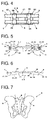
- the innominate front compression part 2 or the innominate rear compression part 3 have the effect of correcting asymmetry of the pelvis A, e.g., asymmetry of the innominates B in FIG. 8 and dislocation of a sacroiliac joint J.
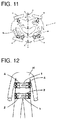
- the thorax front compression part 4 or the thorax rear compression part 5 has the effect of correcting asymmetry of the lower part of the thorax F, e.g., asymmetry of ribs G in FIG. 11 . If a single bone is slightly tilted, one of the compression parts is attached to the body, whereas if a single bone is more severely tilted or bones are tilted at multiple points, the compression parts are attached in combination to the body.
- the combination of the posture corrective brace 1 is preferably determined depending upon whether asymmetry is found near the pelvis A or the lower part of the thorax F, the displacement of a bone, and the amount of asymmetry.
- the posture corrective brace 1 of the present invention is small and lightweight in any combination and therefore is wearable on the body as shown in FIG. 12 . Therefore, a user in a posture corrected by the attached posture corrective brace 1 can perform simple exercises such as arm swinging, forward and backward bending, stamping, walking, and squatting so as to learn exercise patterns of corrected joints in the muscles of the whole body and in the brain. This facilitates continuation of the correction effect.
- the posture corrective brace 1 of the present invention includes a body brace 6 for attaching the innominate front compression part 2, the innominate rear compression part 3, the thorax front compression part 4, or the thorax rear compression part 5 around the circumference of the body.
- Two body braces 6 are used when covering two locations around the pelvis A of the body and the lower part of the thorax F of the body.
- a single body brace 6 is used when covering a location around the pelvis A of the body or the lower part of the thorax F of the body.
- the body brace 6 includes a substantially belt-shaped front frame 7 laterally extended on an abdominal part at the front of the body or on the lower part of the thorax F, two first belt winding mechanisms 10 that are vertically disposed on the left end on the external side of the front frame 7, two second belt winding mechanisms 11 that are vertically disposed on the right end on the external side of the front frame 7, and two unstretchable fastening belts 9, each having one end fastened to the first belt winding mechanism 10 and the other end fastened to the second belt winding mechanism 11.
- the front frame 7 capable of abutting the abdominal part at the front of the body or the lower part of the thorax F is belt-shaped in front view.
- the front frame 7 may have any shape, e.g., a linear shape, a circle, or a curve as long as the front frame 7 is belt-shaped in plan view.
- the front frame 7 is a thin plate made of nonferrous materials such as hard synthetic resin, hard rubber, and aluminum or rigid materials such as wood.
- the two first belt winding mechanisms 10 and the two second belt winding mechanisms 11 are vertically disposed on both sides of the front frame 7.
- the four belt winding mechanisms operate in a separate manner.
- the first belt winding mechanism 10 and the second belt winding mechanism 11 may wind the fastening belt 9 by operating a handle in a ratchet mechanism, may wind the fastening belt 9 by rotating the handle and stop the fastening belt 9 with a stopper, or wind the fastening belt 9 with a hand and fasten the fastening belt 9 with a hook and loop fastener i.e. fabric tape.
- the belt winding mechanisms may have any structure as long as the fastening belt 9 can be wound.
- first belt winding mechanism 10 and the second belt winding mechanism 11 is detachable from the front frame 7.
- first belt winding mechanisms 10 are attached to a mounting plate 52 detachably engaged with a locking protrusion 50 provided on the front frame 7, allowing the first belt winding mechanisms 10 to be detachable from the front frame 7.
- the detachable first belt winding mechanisms 10 allow the posture corrective brace 1 attached to the body to have a free end on one end of the fastening belt 9, facilitating attachment of the posture corrective brace 1 to the body.
- the first belt winding mechanism 10 and the two second belt winding mechanisms 11 each include a ratchet handle 53, a ratchet wheel 54 detachably engaged with the ratchet handle 53, and a ratchet that regulates the ratchet wheel 54 in one rotating direction.
- the ratchet handle 53 is pivoted about a support pin 55 with the ratchet handle 53 and the ratchet wheel 54 engage with each other, thereby rolling and fastening the wound fastening belt 9.
- a release lever 51 disposed at the center of the front frame 7 is operated so as to simultaneously disengage the ratchets from all four ratchet wheels 54.
- the fastening belts 9 will be described below.
- the two fastening belts 9 are vertically disposed with one end fastened to the respective first belt winding mechanisms 10 disposed in the vertical direction and the other end fastened to the respective second belt winding mechanism 11 disposed in the vertical direction.
- a substantially intermediate portion of the fastening belt 9 is inserted into the back frame 8.
- the intermediate portion is inserted through belt insertion portions 36 that are formed on both ends of the outer surface of the back frame 8 so as to allow the insertion of the fastening belt 9.
- the fastening belt 9 may be any one of a vegetable fiber belt, a synthetic fiber belt, a leather belt, or an alamido fiber belt as long as the belt is hardly stretchable by the winding force of the belt winding mechanism while the posture corrective brace 1 is attached to the body.
- the innominate front compression part 2, the innominate rear compression part 3, the thorax front compression part 4, and the thorax rear compression part 5 will be described below.
- the innominate front compression part 2 includes a first front pad 20 and a second front pad 21.
- the first front pad 20 is disposed on the left end of the body contact side of the front frame 7 while the second front pad 21 is disposed on the right end of the body contact side of the front frame 7.
- the first front pad 20 and the second front pad 21 are so large as to compress at least the right and left innominates B in front view.
- the front pads are shaped like rectangles, polygons, or ovals.
- An inclined surface 24 has one end inclined to the body from the center of the front frame 7 in plan view.
- the body contact surfaces of the first and second front pads 20 and 21 form the inclined surfaces 24 that press the front sides of the right and left innominates B so as to guide the innominates B from the forward external side to the backward central side.
- the inclined surfaces 24 are made of materials including glass-containing resin, synthetic resin, and rubber that are so elastic as to prevent pain on the bones under compression and are hard enough to compress the bones.
- the body contact surfaces of the first and second front pads 20 and 21 form the inclined surfaces 24 that press the front sides of the right and left innominates B so as to guide the innominates B from the forward external side to the backward central side. Therefore, the inclined surfaces 24 of the first front pad 20 and the second front pad 21 easily press protrusions on the front sides of the right and left innominates B from the front to the rear, eliminating displacement of the sacroiliac joint J so as to correct asymmetry of the pelvis A.
- the innominate rear compression part 3 includes the back frame 8 laterally extended so as to compress at least the right and left sacroiliac joints J, a first back pad 30 disposed on the left end of the back frame 8 on the internal side thereof and a second back pad 31 disposed on the right end of the back frame 8 on the internal side thereof, and the belt insertion portions 36, allowing the two fastening belts 9 to be inserted thereinto vertically and separately, disposed at positions on the back frame 8 on the external side thereof interposed between the first back pad 30 and the second back pad 31 disposed on the back frame 8 on the internal side thereof, i.e., on the body contact side of the back frame 8.
- the back frame 8 is shaped like a belt abutting the rear side of the body in front view.
- the back frame 8 includes right and left side portions 40 and a central portion 41.
- the shapes of the right and left side portions 40 are not limited and may be linear or circular in plan view.
- the side portions 40 are thin plates made of nonferrous materials such as hard synthetic resin, hard rubber, and aluminum or rigid materials such as wood.
- the central portion 41 is shaped like a belt in front view and is made of a flexible material.
- the back frame 8 may be an integral type including the right and left side portions 40 and the central portion 41 or a divided type including the right and left side portions 40 without the central portion 41. Since the central portion 41 is flexible, the right and left side portions 40 easily follow any change in the curved surface on the circumference of the body.
- the first back pad 30 is disposed on the left end of the body contact side of the back frame 8 while the second back pad 31 is disposed on the right end of the body contact side of the back frame 8.
- the first back pad 30 and the second back pad 31 are so large as to compress at least one of the right and left sacroiliac joints J in front view.
- the back pads are shaped like rectangles, polygons, or ovals.
- An inclined surface 34 has one end inclined to the body from the center of the back frame 8 in plan view.
- the body contact surfaces of the first and second back pads 30 and 31 form the inclined surfaces 34 that press the rear sides of the right and left innominates B so as to guide the innominates B from the forward external side to the backward central side.
- the inclined surfaces 34 are made of materials including glass-containing resin, synthetic resin, and rubber that are so elastic as to prevent pain on the bones under compression and are hard enough to compress the bones.
- the body contact surfaces of the first and second back pads 30 and 31 form the inclined surfaces 34 that press the rear sides of the right and left innominates B so as to guide the innominates B from the backward external side to the central side. Therefore, the inclined surfaces 34 of the first back pad 30 and the second back pad 31 easily press the rear sides of the right and left innominates B diagonally from the rear side of the body toward the sacrum S that is the center of the body.
- the sacroiliac joints J are compressed so as to be suitable with symmetry. This eliminates displacement of the sacroiliac joint J so as to correct asymmetry of the pelvis A.
- the thorax front compression part 4 includes a third front pad 22 and a fourth front pad 23.
- the third front pad 22 is disposed on the left end of the body contact side of the front frame 7 while the fourth front pad 23 is disposed on the right end of the body contact side of the front frame 7.
- the third front pad 22 and the fourth front pad 23 are so large as to compress at least the front sides of the lower parts of the right and left thorax F in front view.
- the front pads are shaped like rectangles, polygons, or ovals.
- An inclined surface 25 has one end inclined to the body from the center of the front frame 7 in plan view.
- the body contact surfaces of the third and fourth front pads 22 and 23 form the inclined surfaces 25 that press the front sides of the right and left ribs G so as to guide the lateral extension of the ribs G from the front.
- the inclined surfaces 25 are made of materials including glass-containing resin, synthetic resin, and rubber that are so elastic as to prevent pain on the bones under compression and are hard enough to compress the bones.
- the body contact surfaces of the third and fourth front pads 22 and 23 form the inclined surfaces 25 that press the front sides of the right and left ribs G so as to guide a lateral extension of the ribs G from the front. Therefore, the inclined surfaces 25 of the third front pad 22 and the fourth front pad 23 easily extend protrusions to the right and left on the front sides of the ribs G at the lower parts of the right and left thorax F, eliminating asymmetry of the lower parts of the thorax F so as to correct asymmetry of the lower parts of the thorax F.
- the thorax rear compression part 5 includes the back frame 8 laterally extended so as to compress at least the rear of the lower parts of the right and left thorax F, a third back pad 32 disposed on the left end of the back frame 8 on the internal side thereof, i.e., on the body side of the back frame 8 and a fourth back pad 33 disposed on the right end of the back frame 8 on the internal side thereof, and the belt insertion portions 36 allowing the two fastening belts 9 to be inserted thereinto vertically and separately, disposed at positions on the back frame 8 on the external side thereof interposed between the third back pad 32 and the fourth back pad 33 disposed on the back frame 8 on the internal side thereof, i.e., on the body side of the back frame 8.
- the back frame 8 is shaped like a belt in abutting the rear side of the body in front view.
- the back frame 8 includes the right and left side portions 40 and the central portion 41.
- the shapes of the right and left side portions 40 are not limited and may be linear or circular in plan view.
- the side portions 40 are thin plates made of nonferrous materials such as hard synthetic resin, hard rubber, and aluminum or rigid materials such as wood.
- the central portion 41 is shaped like a belt in the front view and is made of a flexible material.
- the back frame 8 may be an integral type including the right and left side portions 40 and the central portion 41 or a divided type including the right and left side portions 40 without the central portion 41. Since the central portion 41 is flexible, the right and left side portions 40 easily follow any change in the curved surface on the circumference of the body.
- the third back pad 32 is disposed on the left end of the body contact side of the back frame 8 while the fourth back pad 33 is disposed on the right end of the body contact side of the back frame 8.
- the third back pad 32 and the fourth back pad 33 are so large as to compress at least the rear of the lower parts of the right and left thorax F in front view.
- the back pads are shaped like rectangles, polygons, or ovals.
- An inclined surface 35 has one end inclined to the body from the center of the back frame 8 in plan view.
- the body contact surfaces of the third and fourth front pads 32 and 33 form the inclined surfaces 35 that press the rear sides of the right and left ribs G so as to guide the lateral extension of the rear sides of the ribs G.
- the inclined surfaces 35 are made of materials including glass-containing resin, synthetic resin, and rubber that are so elastic as to prevent pain on the bones under compression and are hard enough to compress the bones.
- the body contact surfaces of the third and fourth back pads 32 and 33 form the inclined surfaces 35 that press the rear sides of the right and left ribs G so as to guide lateral extension of the ribs G from the front.
- the rear side of the lower part of the thorax F is pressed inward so as to laterally extend the front sides of the ribs G, eliminating asymmetry of the lower part of the thorax F so as to correct asymmetry of the lower part of the thorax F.
- the relationship between the body brace 6 to be wrapped around the body and the innominate front compression part 2, the innominate rear compression part 3, the thorax front compression part 4, and the thorax rear compression part 5 will be described below.
- the innominate front compression part 2, the innominate rear compression part 3, the thorax front compression part 4, and the thorax rear compression part 5 are combined in the posture corrective brace 1.
- the compressing parts are combined like the actions of the respective compressing parts.
- the innominate front compression part 2 and the innominate rear compression part 3 that are attached to the body so as to surround the circumference of the pelvis A of the body will be first described below.
- the upper fastening belt 9 of the first belt winding mechanism 10 When the upper fastening belt 9 of the first belt winding mechanism 10 is operated in a winding direction, the upper sides of the first front pad 20 and the first back pad 30 on the left side of the body can first fasten the body.
- the lower fastening belt 9 of the first belt winding mechanism 10 is operated in the winding direction, the lower sides of the first front pad 20 and the first back pad 30 can first fasten the body.
- the upper fastening belt 9 of the second belt winding mechanism 11 When the upper fastening belt 9 of the second belt winding mechanism 11 is operated in the winding direction, the upper sides of the second front pad 21 and the second back pad 31 on the right side of the body can first fasten the body.
- the lower fastening belt 9 of the second belt winding mechanism 11 When the lower fastening belt 9 of the second belt winding mechanism 11 is operated in the winding direction, the lower sides of the second front pad 21 and the second back pad 31 on the right side of the body can first fasten the body.
- the innominate front compression part 2 and the innominate rear compression part 3 are attached to the body, the pressures of the first front pad 20, the second front pad 21, the first back pad 30, and the second back pad 31 to the body can be freely adjusted.
- the pressure can be adjusted only on the part where the loosening is felt. This can always apply any degree of pressure to the body, easily eliminating displacement of the sacroiliac joint J and asymmetry of the pelvis A.
- the thorax front compression part 4 and the thorax rear compression part 5 that wrap around the body so as to surround the circumference of the lower part of the thorax F of the body will be described below.
- the upper fastening belt 9 of the first belt winding mechanism 10 When the upper fastening belt 9 of the first belt winding mechanism 10 is operated in the winding direction, the upper sides of the third front pad 22 and the third back pad 32 on the left side of the body can first fasten the body.
- the lower fastening belt 9 of the first belt winding mechanism 10 is operated in the winding direction, the lower sides of the third front pad 22 and the third back pad 32 on the left side of the body can first fasten the body.
- the upper fastening belt 9 of the second belt winding mechanism 11 When the upper fastening belt 9 of the second belt winding mechanism 11 is operated in the winding direction, the upper sides of the fourth front pad 23 and the fourth back pad 33 on the right side of the body can first fasten the body.
- the lower fastening belt 9 of the second belt winding mechanism 11 When the lower fastening belt 9 of the second belt winding mechanism 11 is operated in the winding direction, the lower sides of the fourth front pad 23 and the fourth back pad 33 on the right side of the body can first fasten the body.
- the pressures of the third front pad 22, the fourth front pad 23, the third back pad 32, and the fourth back pad 33 to the body can be freely adjusted.
- the pressure can be adjusted only on the part where the loosening is felt. This can always apply any degree of pressure to the body, easily eliminating asymmetry of the ribs G and asymmetry of the lower part of the thorax F.
- the posture corrective brace 1 as one of the present embodiments can be used as follows: simple exercises such as stamping, walking, and squatting are performed while correcting asymmetry of bones with the posture corrective brace 1, and therefore exercise patterns having no asymmetry of bones and joints can be easily learned in the brain and in the muscles of the whole body.
- the belt winding mechanism with a ratchet mechanism includes a combination of the innominate front compression part 2, the innominate rear compression part 3, the thorax front compression part 4, and the thorax rear compression part 5.
- the posture corrective brace 1 includes the attached innominate front compression part 2 and innominate rear compression part 3.
- the first belt winding mechanisms 10 are detached from the front frame 7 at the mounting plate 52.
- the front frame 7 is disposed on the front side of the body, the fastening belts 9 are wrapped from the back side to the front side, and then the mounting plate 52 combined with the first belt winding mechanisms 10 is engaged with the locking protrusion 50 so as to be attached to the front frame 7.
- the back frame 8 in this state is located on the back side of the body.
- the ratchet handles 53 of the two first belt winding mechanisms 10 and the two second belt winding mechanisms 11 are suitably operated to fasten the two fastening belts 9. Therefore, the first front pad 20 of the front frame 7 presses the front end of the left side of the left innominate B toward the sacrum S; meanwhile, the second front pad 21 presses the front end of the right side of the right innominate B toward the sacrum S. At this point, the first front pad 20 and the second front pad 21 each include the inclined surface 24 and therefore can effectively press the right and left innominates B toward the sacrum S.
- the back frame 8 is in abutting the back of the body, the first back pad 30 presses the rear end of the left innominate B toward the sacrum S, and the second back pad 31 presses the rear end of the right innominate B toward the sacrum S.
- the first back pad 30 and the second back pad 31 each include the inclined surface 34 and therefore can effectively press the right and left innominates B toward the sacrum S.
- the posture corrective brace 1 includes the thorax front compression part 4 and the thorax rear compression part 5.
- the first belt winding mechanism 10 is detached from the front frame 7 at the mounting plate 52.
- the front frame 7 is disposed on the front side of the body, the fastening belts 9 are wrapped from the back side to the front side, and then the mounting plate 52 combined with the first belt winding mechanisms 10 is engaged with the locking protrusion 50 so as to be attached to the front frame 7.
- the back frame 8 in this state is located on the back side of the body.
- the posture corrective brace 1 is attached to the body at lower part R2 of the thorax F.
- the ratchet handles 53 of the two first belt winding mechanisms 10 and the two second belt winding mechanisms 11 are suitably operated to fasten the two fastening belts 9. Therefore, the third front pad 22 of the front frame 7 presses the left ribs G so as to laterally extend the ribs G; meanwhile, the fourth front pad 23 presses the right ribs G so as to laterally extend the ribs G. At this point, the third front pad 22 and the fourth front pad 23 each include the inclined surface 25 and therefore can effectively press the right and left ribs G so as to laterally extend the ribs G.
- the back frame 8 is abutting the back of the body
- the third back pad 32 presses the rear end of the lower part of the left thorax F so as to extend the lower part of the thorax F on the front side
- the fourth back pad 33 presses the rear end of the lower part of the right thorax F so as to extend the lower part of the right thorax F on the front side.
- the third back pad 32 and the fourth back pad 33 each include the inclined surface 35 and therefore can effectively press the thorax F so as to laterally extend the front sides of the lower parts of the right and left thorax F.
- the user H performs light exercises such as walking, stamping, squatting and exercises using the part above the thorax F, e.g., aspiration, forward and backward bending, and arm swinging.
- light exercises such as walking, stamping, squatting and exercises using the part above the thorax F, e.g., aspiration, forward and backward bending, and arm swinging.
- exercises such as aspiration, forward and backward bending, and arm swinging laterally extend the lower part of the thorax F.
- This moves upper part R1 of the thorax F in FIG. 10 upward but does not move the lower part R2 of the thorax F upward because the lower part R2 is fastened by the third and fourth front pads 22 and 23.
- This corrects asymmetry of the ribs G and eliminates asymmetry of the thorax F.
- the fastening belt 9 is fastened by the first belt winding mechanism 10 and the second belt winding mechanism 11. Specifically, the fastening belt 9 moves in a fastened state and is fastened in a loosened state, correcting asymmetry of the pelvis A and the lower part of the thorax F.
- Asymmetry is preferably corrected by the posture corrective brace 1 for about ten minutes at a time, twice or three times in a week. Typically, posture is improved by one or two times of correction.
Landscapes
- Health & Medical Sciences (AREA)
- Nursing (AREA)
- Orthopedic Medicine & Surgery (AREA)
- Engineering & Computer Science (AREA)
- Biomedical Technology (AREA)
- Heart & Thoracic Surgery (AREA)
- Vascular Medicine (AREA)
- Life Sciences & Earth Sciences (AREA)
- Animal Behavior & Ethology (AREA)
- General Health & Medical Sciences (AREA)
- Public Health (AREA)
- Veterinary Medicine (AREA)
- Orthopedics, Nursing, And Contraception (AREA)
Applications Claiming Priority (1)
| Application Number | Priority Date | Filing Date | Title |
|---|---|---|---|
| PCT/JP2013/060846 WO2014167674A1 (ja) | 2013-04-10 | 2013-04-10 | 姿勢矯正器 |
Publications (2)
| Publication Number | Publication Date |
|---|---|
| EP2985010A1 true EP2985010A1 (de) | 2016-02-17 |
| EP2985010A4 EP2985010A4 (de) | 2016-11-23 |
Family
ID=51689108
Family Applications (1)
| Application Number | Title | Priority Date | Filing Date |
|---|---|---|---|
| EP13881695.4A Withdrawn EP2985010A4 (de) | 2013-04-10 | 2013-04-10 | Haltungskorrekturvorrichtung |
Country Status (8)
| Country | Link |
|---|---|
| US (1) | US10166135B2 (de) |
| EP (1) | EP2985010A4 (de) |
| JP (1) | JP5657837B1 (de) |
| KR (1) | KR102160755B1 (de) |
| CN (1) | CN104394811B (de) |
| AU (1) | AU2013386035B2 (de) |
| CA (1) | CA2878196C (de) |
| WO (1) | WO2014167674A1 (de) |
Families Citing this family (24)
| Publication number | Priority date | Publication date | Assignee | Title |
|---|---|---|---|---|
| CN105030476B (zh) * | 2015-07-10 | 2017-09-19 | 哈尔滨天愈康复医疗机器人有限公司 | 一种脊椎病康复治疗机器人 |
| KR102541908B1 (ko) * | 2015-07-21 | 2023-06-09 | 삼성전자주식회사 | 프레임 모듈 및 이를 포함하는 운동 보조 장치 |
| JP2017038815A (ja) * | 2015-08-20 | 2017-02-23 | 株式会社アルファ技研 | 身体装着用具 |
| US10206805B2 (en) | 2016-01-11 | 2019-02-19 | Ryan C. Murdock | External spinal brace |
| CA2920670C (en) | 2016-02-12 | 2025-09-16 | Derek Nolt | SHOULDER SUPPORTS AND METHODS OF USE |
| JP6633449B2 (ja) * | 2016-05-13 | 2020-01-22 | 丸光産業株式会社 | 腰部サポートベルト |
| JP6376633B1 (ja) * | 2017-01-16 | 2018-08-22 | 有限会社Q・O・L | 仙骨押圧具および仙骨押圧ユニット |
| JPWO2018173098A1 (ja) * | 2017-03-21 | 2020-01-23 | 有限会社Opti | 骨盤用ベルト |
| ES1184534Y (es) * | 2017-04-21 | 2017-09-08 | Rm Urgecamino S L | Dispositivo corrector postural |
| JP7118388B2 (ja) * | 2017-07-25 | 2022-08-16 | 明治 岩上 | 骨盤ベルトと押圧矯正器具との組み合わせからなる骨盤矯正用具 |
| US11627766B2 (en) | 2017-09-22 | 2023-04-18 | Steven F. Bierman | Lumbar supportive wetsuit |
| KR101887381B1 (ko) * | 2017-10-31 | 2018-08-10 | 연세대학교 산학협력단 | 경사진 팽창부가 구비된 밴드형 척추보조기구 |
| USD873422S1 (en) | 2017-11-20 | 2020-01-21 | Derek Nolt | Shoulder brace |
| DE102018203443A1 (de) * | 2018-03-07 | 2019-09-12 | Bauerfeind Ag | Mobilisierende Hüftorthese |
| WO2019179341A1 (zh) * | 2018-03-20 | 2019-09-26 | 苏英杰 | 肋骨支撑装置 |
| US11053077B2 (en) * | 2018-06-08 | 2021-07-06 | Maria Gaudio | Pelvic braces and methods for using same |
| KR102074592B1 (ko) * | 2018-10-30 | 2020-02-06 | 윤희준 | 휴대용 운동기구 |
| US11554069B1 (en) * | 2019-11-22 | 2023-01-17 | Tom John Langmacher | Stretching belt for stretching of the spine |
| KR102376666B1 (ko) * | 2020-01-06 | 2022-03-18 | 김대근 | 허리 지지 교정벨트 |
| CN111544179B (zh) * | 2020-06-12 | 2022-10-21 | 丁舒雅 | 一种妇产科专用的产后康复按压装置及其使用方法 |
| KR20230032779A (ko) | 2021-08-31 | 2023-03-07 | 이민영 | 스마트 디바이스를 이용한 보행 교정 시스템 |
| KR102858789B1 (ko) * | 2023-11-20 | 2025-09-11 | 김수지 | 필라테스용 흉식호흡 및 척추직립유도 운동기구 |
| CN117338289B (zh) * | 2023-11-22 | 2024-07-16 | 上海长征医院 | 腰部支撑智能保护装置及方法 |
| CN119935571B (zh) * | 2025-01-03 | 2025-12-05 | 南京理工大学 | 一种反映人体胸廓运动特性的碰撞假人胸廓结构 |
Family Cites Families (15)
| Publication number | Priority date | Publication date | Assignee | Title |
|---|---|---|---|---|
| US3548817A (en) * | 1968-04-29 | 1970-12-22 | Ronald F Mittasch | Orthopedic traction belt |
| FR2687062B1 (fr) * | 1992-02-07 | 1999-07-30 | Charles Lelli | Ceinture de maintien lombaire. |
| JPH0889521A (ja) * | 1994-09-21 | 1996-04-09 | Masao Ikeo | 妊婦用ベルト |
| JPH09553A (ja) * | 1995-06-23 | 1997-01-07 | Sumitomo Rubber Ind Ltd | 腰痛矯正ベルト |
| US5647824A (en) * | 1995-10-25 | 1997-07-15 | Levenson; Bruce Adam | Weight lifter's belt incorporating strap ratchet and nylon strap |
| US20010008955A1 (en) * | 1999-06-01 | 2001-07-19 | Garth Geoffrey C. | Back brace |
| US6500137B1 (en) | 2001-08-30 | 2002-12-31 | Joseph L. Molino | Pelvic region orthotic device |
| US8021287B2 (en) | 2007-04-25 | 2011-09-20 | Backproject Corporation | Restraint, reposition, traction and exercise device and method |
| JP5079446B2 (ja) * | 2007-10-22 | 2012-11-21 | 有限会社シーシェル | 仙腸関節包内運動矯正ベルト |
| CN201481609U (zh) * | 2009-09-18 | 2010-05-26 | 何远流 | 腰支撑固护垫 |
| JP3164201U (ja) * | 2010-09-06 | 2010-11-18 | 玉川衛材株式会社 | 骨盤押圧パッド及び骨盤押圧パッド付き骨盤矯正ベルト |
| WO2012109524A1 (en) * | 2011-02-10 | 2012-08-16 | Ossur Hf | Tightening system for an orthopedic article |
| CN202397661U (zh) * | 2012-01-03 | 2012-08-29 | 徐浩钟 | 收腹正腰脊器 |
| CN202776661U (zh) * | 2012-06-05 | 2013-03-13 | 李四波 | 胸腰椎外固定支架 |
| CN103598941A (zh) * | 2013-11-27 | 2014-02-26 | 崔哲权 | 腰带 |
-
2013
- 2013-04-10 WO PCT/JP2013/060846 patent/WO2014167674A1/ja not_active Ceased
- 2013-04-10 KR KR1020147034560A patent/KR102160755B1/ko active Active
- 2013-04-10 CA CA2878196A patent/CA2878196C/en active Active
- 2013-04-10 AU AU2013386035A patent/AU2013386035B2/en not_active Ceased
- 2013-04-10 EP EP13881695.4A patent/EP2985010A4/de not_active Withdrawn
- 2013-04-10 CN CN201380030353.XA patent/CN104394811B/zh not_active Expired - Fee Related
- 2013-04-10 JP JP2014514639A patent/JP5657837B1/ja active Active
-
2015
- 2015-06-22 US US14/745,931 patent/US10166135B2/en active Active
Also Published As
| Publication number | Publication date |
|---|---|
| US20150282974A1 (en) | 2015-10-08 |
| AU2013386035B2 (en) | 2018-10-04 |
| AU2013386035A1 (en) | 2015-01-22 |
| CN104394811A (zh) | 2015-03-04 |
| CN104394811B (zh) | 2017-12-08 |
| US10166135B2 (en) | 2019-01-01 |
| CA2878196A1 (en) | 2014-10-16 |
| JP5657837B1 (ja) | 2015-01-21 |
| EP2985010A4 (de) | 2016-11-23 |
| WO2014167674A1 (ja) | 2014-10-16 |
| CA2878196C (en) | 2020-09-01 |
| KR20150143271A (ko) | 2015-12-23 |
| JPWO2014167674A1 (ja) | 2017-02-16 |
| KR102160755B1 (ko) | 2020-09-28 |
Similar Documents
| Publication | Publication Date | Title |
|---|---|---|
| AU2013386035B2 (en) | Posture correction device | |
| AU634371B2 (en) | Chiropractic belt | |
| US7150719B2 (en) | Thoraco-lumbar spine support/brace | |
| US9522077B1 (en) | Adjustable dual function spinal exoskeleton active spinal orthosis | |
| CN102046114A (zh) | 骨盆带 | |
| US9855162B2 (en) | Spinal orthosis | |
| US12097139B2 (en) | Posture and lifting orthotic | |
| US12514774B2 (en) | Spinal weighting devices | |
| JP5750396B2 (ja) | 脊椎変形矯正装具 | |
| WO2018131231A1 (ja) | 仙骨押圧具および仙骨押圧ユニット | |
| US12016822B2 (en) | Back brace with repositionable pressure nodules | |
| KR20200005261A (ko) | 허리 보호 벨트 | |
| JP6195802B2 (ja) | 関節包内矯正具 | |
| JP6112732B2 (ja) | 姿勢矯正器 | |
| JP7698165B2 (ja) | 骨盤矯正用サポータ | |
| CN207886326U (zh) | 脊柱过伸矫形器 | |
| KR200476376Y1 (ko) | 인체공학적 구조를 갖는 의료용 복대 | |
| JPH0584316U (ja) | 腰痛帯 | |
| CN115337133A (zh) | 一种可弯曲脊柱侧弯矫形器 | |
| KR200444532Y1 (ko) | 휜 다리 교정용 운동기구 | |
| JP3185428U (ja) | 運動用サポーター | |
| KR102858789B1 (ko) | 필라테스용 흉식호흡 및 척추직립유도 운동기구 | |
| JP2012000264A (ja) | 運動用サポーター | |
| JP6949308B2 (ja) | 矯正用締め付け腰ベルト及びその締め付け方法 | |
| Stuttle | 23 The Upside-down Flexion Back Brace |
Legal Events
| Date | Code | Title | Description |
|---|---|---|---|
| PUAI | Public reference made under article 153(3) epc to a published international application that has entered the european phase |
Free format text: ORIGINAL CODE: 0009012 |
|
| 17P | Request for examination filed |
Effective date: 20151019 |
|
| AK | Designated contracting states |
Kind code of ref document: A1 Designated state(s): AL AT BE BG CH CY CZ DE DK EE ES FI FR GB GR HR HU IE IS IT LI LT LU LV MC MK MT NL NO PL PT RO RS SE SI SK SM TR |
|
| AX | Request for extension of the european patent |
Extension state: BA ME |
|
| DAX | Request for extension of the european patent (deleted) | ||
| A4 | Supplementary search report drawn up and despatched |
Effective date: 20161025 |
|
| RIC1 | Information provided on ipc code assigned before grant |
Ipc: A61F 5/03 20060101ALI20161019BHEP Ipc: A61F 5/01 20060101AFI20161019BHEP Ipc: A61F 5/02 20060101ALI20161019BHEP |
|
| STAA | Information on the status of an ep patent application or granted ep patent |
Free format text: STATUS: THE APPLICATION IS DEEMED TO BE WITHDRAWN |
|
| 18D | Application deemed to be withdrawn |
Effective date: 20170523 |