EP2985089B1 - Procédé de formage d'une aube gonflée - Google Patents
Procédé de formage d'une aube gonflée Download PDFInfo
- Publication number
- EP2985089B1 EP2985089B1 EP15180393.9A EP15180393A EP2985089B1 EP 2985089 B1 EP2985089 B1 EP 2985089B1 EP 15180393 A EP15180393 A EP 15180393A EP 2985089 B1 EP2985089 B1 EP 2985089B1
- Authority
- EP
- European Patent Office
- Prior art keywords
- aerofoil
- region
- forming
- stress
- datum
- Prior art date
- Legal status (The legal status is an assumption and is not a legal conclusion. Google has not performed a legal analysis and makes no representation as to the accuracy of the status listed.)
- Active
Links
Images


Classifications
-
- F—MECHANICAL ENGINEERING; LIGHTING; HEATING; WEAPONS; BLASTING
- F01—MACHINES OR ENGINES IN GENERAL; ENGINE PLANTS IN GENERAL; STEAM ENGINES
- F01D—NON-POSITIVE DISPLACEMENT MACHINES OR ENGINES, e.g. STEAM TURBINES
- F01D5/00—Blades; Blade-carrying members; Heating, heat-insulating, cooling or antivibration means on the blades or the members
- F01D5/12—Blades
- F01D5/14—Form or construction
- F01D5/18—Hollow blades, i.e. blades with cooling or heating channels or cavities; Heating, heat-insulating or cooling means on blades
-
- B—PERFORMING OPERATIONS; TRANSPORTING
- B21—MECHANICAL METAL-WORKING WITHOUT ESSENTIALLY REMOVING MATERIAL; PUNCHING METAL
- B21D—WORKING OR PROCESSING OF SHEET METAL OR METAL TUBES, RODS OR PROFILES WITHOUT ESSENTIALLY REMOVING MATERIAL; PUNCHING METAL
- B21D26/00—Shaping without cutting otherwise than using rigid devices or tools or yieldable or resilient pads, i.e. applying fluid pressure or magnetic forces
- B21D26/02—Shaping without cutting otherwise than using rigid devices or tools or yieldable or resilient pads, i.e. applying fluid pressure or magnetic forces by applying fluid pressure
- B21D26/053—Shaping without cutting otherwise than using rigid devices or tools or yieldable or resilient pads, i.e. applying fluid pressure or magnetic forces by applying fluid pressure characterised by the material of the blanks
- B21D26/059—Layered blanks
-
- B—PERFORMING OPERATIONS; TRANSPORTING
- B21—MECHANICAL METAL-WORKING WITHOUT ESSENTIALLY REMOVING MATERIAL; PUNCHING METAL
- B21D—WORKING OR PROCESSING OF SHEET METAL OR METAL TUBES, RODS OR PROFILES WITHOUT ESSENTIALLY REMOVING MATERIAL; PUNCHING METAL
- B21D53/00—Making other particular articles
- B21D53/78—Making other particular articles propeller blades; turbine blades
-
- B—PERFORMING OPERATIONS; TRANSPORTING
- B23—MACHINE TOOLS; METAL-WORKING NOT OTHERWISE PROVIDED FOR
- B23K—SOLDERING OR UNSOLDERING; WELDING; CLADDING OR PLATING BY SOLDERING OR WELDING; CUTTING BY APPLYING HEAT LOCALLY, e.g. FLAME CUTTING; WORKING BY LASER BEAM
- B23K20/00—Non-electric welding by applying impact or other pressure, with or without the application of heat, e.g. cladding or plating
- B23K20/02—Non-electric welding by applying impact or other pressure, with or without the application of heat, e.g. cladding or plating by means of a press ; Diffusion bonding
- B23K20/023—Thermo-compression bonding
-
- B—PERFORMING OPERATIONS; TRANSPORTING
- B23—MACHINE TOOLS; METAL-WORKING NOT OTHERWISE PROVIDED FOR
- B23K—SOLDERING OR UNSOLDERING; WELDING; CLADDING OR PLATING BY SOLDERING OR WELDING; CUTTING BY APPLYING HEAT LOCALLY, e.g. FLAME CUTTING; WORKING BY LASER BEAM
- B23K20/00—Non-electric welding by applying impact or other pressure, with or without the application of heat, e.g. cladding or plating
- B23K20/22—Non-electric welding by applying impact or other pressure, with or without the application of heat, e.g. cladding or plating taking account of the properties of the materials to be welded
- B23K20/233—Non-electric welding by applying impact or other pressure, with or without the application of heat, e.g. cladding or plating taking account of the properties of the materials to be welded without ferrous layer
- B23K20/2333—Non-electric welding by applying impact or other pressure, with or without the application of heat, e.g. cladding or plating taking account of the properties of the materials to be welded without ferrous layer one layer being aluminium, magnesium or beryllium
-
- B—PERFORMING OPERATIONS; TRANSPORTING
- B23—MACHINE TOOLS; METAL-WORKING NOT OTHERWISE PROVIDED FOR
- B23K—SOLDERING OR UNSOLDERING; WELDING; CLADDING OR PLATING BY SOLDERING OR WELDING; CUTTING BY APPLYING HEAT LOCALLY, e.g. FLAME CUTTING; WORKING BY LASER BEAM
- B23K20/00—Non-electric welding by applying impact or other pressure, with or without the application of heat, e.g. cladding or plating
- B23K20/22—Non-electric welding by applying impact or other pressure, with or without the application of heat, e.g. cladding or plating taking account of the properties of the materials to be welded
- B23K20/233—Non-electric welding by applying impact or other pressure, with or without the application of heat, e.g. cladding or plating taking account of the properties of the materials to be welded without ferrous layer
- B23K20/2336—Non-electric welding by applying impact or other pressure, with or without the application of heat, e.g. cladding or plating taking account of the properties of the materials to be welded without ferrous layer both layers being aluminium
-
- F—MECHANICAL ENGINEERING; LIGHTING; HEATING; WEAPONS; BLASTING
- F01—MACHINES OR ENGINES IN GENERAL; ENGINE PLANTS IN GENERAL; STEAM ENGINES
- F01D—NON-POSITIVE DISPLACEMENT MACHINES OR ENGINES, e.g. STEAM TURBINES
- F01D9/00—Stators
- F01D9/02—Nozzles; Nozzle boxes; Stator blades; Guide conduits, e.g. individual nozzles
- F01D9/04—Nozzles; Nozzle boxes; Stator blades; Guide conduits, e.g. individual nozzles forming ring or sector
- F01D9/041—Nozzles; Nozzle boxes; Stator blades; Guide conduits, e.g. individual nozzles forming ring or sector using blades
-
- B—PERFORMING OPERATIONS; TRANSPORTING
- B23—MACHINE TOOLS; METAL-WORKING NOT OTHERWISE PROVIDED FOR
- B23K—SOLDERING OR UNSOLDERING; WELDING; CLADDING OR PLATING BY SOLDERING OR WELDING; CUTTING BY APPLYING HEAT LOCALLY, e.g. FLAME CUTTING; WORKING BY LASER BEAM
- B23K2103/00—Materials to be soldered, welded or cut
- B23K2103/08—Non-ferrous metals or alloys
- B23K2103/10—Aluminium or alloys thereof
-
- B—PERFORMING OPERATIONS; TRANSPORTING
- B23—MACHINE TOOLS; METAL-WORKING NOT OTHERWISE PROVIDED FOR
- B23K—SOLDERING OR UNSOLDERING; WELDING; CLADDING OR PLATING BY SOLDERING OR WELDING; CUTTING BY APPLYING HEAT LOCALLY, e.g. FLAME CUTTING; WORKING BY LASER BEAM
- B23K2103/00—Materials to be soldered, welded or cut
- B23K2103/08—Non-ferrous metals or alloys
- B23K2103/14—Titanium or alloys thereof
-
- B—PERFORMING OPERATIONS; TRANSPORTING
- B23—MACHINE TOOLS; METAL-WORKING NOT OTHERWISE PROVIDED FOR
- B23K—SOLDERING OR UNSOLDERING; WELDING; CLADDING OR PLATING BY SOLDERING OR WELDING; CUTTING BY APPLYING HEAT LOCALLY, e.g. FLAME CUTTING; WORKING BY LASER BEAM
- B23K2103/00—Materials to be soldered, welded or cut
- B23K2103/18—Dissimilar materials
-
- B—PERFORMING OPERATIONS; TRANSPORTING
- B23—MACHINE TOOLS; METAL-WORKING NOT OTHERWISE PROVIDED FOR
- B23P—METAL-WORKING NOT OTHERWISE PROVIDED FOR; COMBINED OPERATIONS; UNIVERSAL MACHINE TOOLS
- B23P15/00—Making specific metal objects by operations not covered by a single other subclass or a group in this subclass
- B23P15/04—Making specific metal objects by operations not covered by a single other subclass or a group in this subclass turbine or like blades from several pieces
-
- F—MECHANICAL ENGINEERING; LIGHTING; HEATING; WEAPONS; BLASTING
- F05—INDEXING SCHEMES RELATING TO ENGINES OR PUMPS IN VARIOUS SUBCLASSES OF CLASSES F01-F04
- F05D—INDEXING SCHEME FOR ASPECTS RELATING TO NON-POSITIVE-DISPLACEMENT MACHINES OR ENGINES, GAS-TURBINES OR JET-PROPULSION PLANTS
- F05D2220/00—Application
- F05D2220/30—Application in turbines
- F05D2220/32—Application in turbines in gas turbines
-
- F—MECHANICAL ENGINEERING; LIGHTING; HEATING; WEAPONS; BLASTING
- F05—INDEXING SCHEMES RELATING TO ENGINES OR PUMPS IN VARIOUS SUBCLASSES OF CLASSES F01-F04
- F05D—INDEXING SCHEME FOR ASPECTS RELATING TO NON-POSITIVE-DISPLACEMENT MACHINES OR ENGINES, GAS-TURBINES OR JET-PROPULSION PLANTS
- F05D2230/00—Manufacture
- F05D2230/20—Manufacture essentially without removing material
- F05D2230/23—Manufacture essentially without removing material by permanently joining parts together
- F05D2230/232—Manufacture essentially without removing material by permanently joining parts together by welding
- F05D2230/236—Diffusion bonding
-
- F—MECHANICAL ENGINEERING; LIGHTING; HEATING; WEAPONS; BLASTING
- F05—INDEXING SCHEMES RELATING TO ENGINES OR PUMPS IN VARIOUS SUBCLASSES OF CLASSES F01-F04
- F05D—INDEXING SCHEME FOR ASPECTS RELATING TO NON-POSITIVE-DISPLACEMENT MACHINES OR ENGINES, GAS-TURBINES OR JET-PROPULSION PLANTS
- F05D2230/00—Manufacture
- F05D2230/40—Heat treatment
-
- F—MECHANICAL ENGINEERING; LIGHTING; HEATING; WEAPONS; BLASTING
- F05—INDEXING SCHEMES RELATING TO ENGINES OR PUMPS IN VARIOUS SUBCLASSES OF CLASSES F01-F04
- F05D—INDEXING SCHEME FOR ASPECTS RELATING TO NON-POSITIVE-DISPLACEMENT MACHINES OR ENGINES, GAS-TURBINES OR JET-PROPULSION PLANTS
- F05D2230/00—Manufacture
- F05D2230/60—Assembly methods
-
- F—MECHANICAL ENGINEERING; LIGHTING; HEATING; WEAPONS; BLASTING
- F05—INDEXING SCHEMES RELATING TO ENGINES OR PUMPS IN VARIOUS SUBCLASSES OF CLASSES F01-F04
- F05D—INDEXING SCHEME FOR ASPECTS RELATING TO NON-POSITIVE-DISPLACEMENT MACHINES OR ENGINES, GAS-TURBINES OR JET-PROPULSION PLANTS
- F05D2300/00—Materials; Properties thereof
- F05D2300/10—Metals, alloys or intermetallic compounds
- F05D2300/12—Light metals
- F05D2300/121—Aluminium
-
- F—MECHANICAL ENGINEERING; LIGHTING; HEATING; WEAPONS; BLASTING
- F05—INDEXING SCHEMES RELATING TO ENGINES OR PUMPS IN VARIOUS SUBCLASSES OF CLASSES F01-F04
- F05D—INDEXING SCHEME FOR ASPECTS RELATING TO NON-POSITIVE-DISPLACEMENT MACHINES OR ENGINES, GAS-TURBINES OR JET-PROPULSION PLANTS
- F05D2300/00—Materials; Properties thereof
- F05D2300/10—Metals, alloys or intermetallic compounds
- F05D2300/13—Refractory metals, i.e. Ti, V, Cr, Zr, Nb, Mo, Hf, Ta, W
- F05D2300/133—Titanium
Definitions
- the present invention relates to a method of forming an inflated aerofoil, and in preferred implementations is particularly suitable for forming an aerofoil for use as a blade or a vane in a gas turbine engine.
- Document GB-A-2304613 discloses a method of forming an inflated aerofoil from a layered, planar preform comprising the steps of hot creep forming and inflating the preform to form an intermediate aerofoil and subsequently removing material from the intermediate aerofoil.
- Gas turbine engines comprise compressor and turbine arrangements having alternating stages of rotating aerofoil blades and stationary aerofoil vanes.
- a number of axial flow compressors are often provided which each supply high pressure air either to another downstream compressor or to a combustor.
- the outlet guide vanes are also provided in the form of stationary aerofoils.
- Figure 1 shows a chordal cross-section through an intermediate and unfinished aerofoil 1 following the hot creep forming and inflation process, but before the service lugs at each end of the aerofoil have been removed during a subsequent finishing process.
- the intermediate aerofoil is created to have a desired degree of curvature to both its concave pressure side 2 and its convex suction side 3.
- figure 2 shows the chordal cross-section which can result following removal of the service lugs.
- the degree of curvature present in the intermediate aerofoil has relaxed or "sprung-back" following removal of the service lugs, thereby changing the shape of the aerofoil such that it no longer conforms to its design shape.
- a method of forming an inflated aerofoil comprising the steps of: forming a layered, planar pre-form; providing at least one stress-relieving opening through the pre-form; hot creep forming and inflating the pre-form to form an intermediate aerofoil; and subsequently removing material from the intermediate aerofoil, including at least a region containing the or each stress-relieving opening, to form a finished aerofoil.
- the method may include the step of providing at least one datum region on the pre-form, for use in locating the pre-form during said hot creep forming and inflating steps, wherein said step of forming said at least one stress-relieving opening involves forming the or each opening in or adjacent a said datum region, and said step of removing material from the intermediate aerofoil involves removing the or each datum region.
- the method further includes a step of defining on the preform a nominal profile of the aerofoil to be formed.
- Said step of defining a nominal profile optionally involves machining the nominal profile on at least one outwardly directed face of the pre-form.
- the or at least one said stress-relieving opening may be provided through the pre-form at a position located between a said datum region and a main region of the nominal profile of the aerofoil.
- the or at least one said stress-relieving opening is provided in the form of a slot through the pre-form.
- the or at least one said slot is located entirely within the periphery of said pre-form.
- the or at least one said slot has at least one end which is open to the periphery of the pre-form.
- the or at least one said slot may be elongate and substantially straight.
- the or at least one said slot may furcated.
- the method further comprises the step of profiling the pre-form to define a leading edge and a trailing edge for the aerofoil.
- Said step of profiling can involve cutting the pre-form to define the leading edge and the trailing edge.
- Said step of profiling may also, or alternatively, involve cutting the pre-form to define a peripheral edge of the or each datum region.
- said step of providing a layered, planar preform involves bonding together a pair of outer skins.
- the outer skins may comprise titanium or aluminium.
- said outer skins are diffusion bonded to one another.
- the method further comprises a step of applying a stop-off material in a predefined region between the outer skins prior to said step of bonding the skins together, to thereby define an inflatable region within the pre-form.
- the aerofoil may a blade or a vane for a gas turbine engine, and may preferably be an outlet guide vane for a gas turbine engine.
- a ducted fan gas turbine engine which may incorporate aerofoils made via the method of the invention is generally indicated at 10 and has a principal and rotational axis X-X.
- the engine comprises, in axial flow series, an air intake 11, a propulsive fan 12, an intermediate pressure compressor 13, a high-pressure compressor 14, combustion equipment 15, a high-pressure turbine 16, an intermediate pressure turbine 17, a low-pressure turbine 18 and a core engine exhaust nozzle 19.
- a nacelle 21 generally surrounds the engine 10 and defines the intake 11, a bypass duct 22 and a bypass exhaust nozzle 23.
- air entering the intake 11 is accelerated by the fan 12 to produce two air flows: a first air flow A into the intermediate pressure compressor 13 and a second air flow B which passes through the bypass duct 22 to provide propulsive thrust.
- the intermediate pressure compressor 13 compresses the air flow A directed into it before delivering that air, via a series of intermediate pressure outlet guide vanes 24, to the high pressure compressor 14 where further compression takes place.
- the compressed air exhausted from the high-pressure compressor 14 is directed, via a series of high pressure outlet guide vanes 25, into the combustion equipment 15 where it is mixed with fuel and the mixture combusted.
- the resultant hot combustion products then expand through, and thereby drive the high, intermediate and low-pressure turbines 16, 17, 18 before being exhausted through the nozzle 19 to provide additional propulsive thrust.
- the high, intermediate and low-pressure turbines respectively drive the high and intermediate pressure compressors 14, 13 and the fan 12 by suitable interconnecting shafts.
- the intermediate pressure guide vanes 24 and the high pressure guide vanes 25 comprise aerofoils which may be formed by the method of the present invention.
- the fan 12, intermediate and high pressure compressors 13, 14 and the high, intermediate and low pressure turbines 16, 17, 18 also each comprise blades in the form of aerofoils which can be formed by the method of the present invention.
- the method of the present invention will be particularly well suited to producing large outlet guide vanes.
- the method of the present invention shares some steps with prior art methods for producing inflated aerofoils, and these can be understood from a consideration of figures 4 and 5 .
- a layered planar pre-form 30 is constructed as shown in figure 4 .
- the pre-form 30 is formed from a pair of planar outer skins or sheets 31, 32 which are superimposed on one another as shown.
- the outer sheets 31, 32 are shown to be of generally rectangular configuration, having a length which is somewhat longer than the length of the aerofoil which is to be produced.
- the sheets 31, 32 may be formed of any suitable material, although it is envisaged that the sheets 31, 32 will be formed from titanium or aluminium. In preferred arrangements, the two sheets 31, 32 each have a thickness of approximately 6 millimetres.
- a stop-off material such as yttria, boron nitride, graphite or alumina is applied to the inside surfaces of the two sheets 31, 32, over a predefined region 33.
- the superimposed sheets 31, 32 are then diffusion bonded by applying heat and pressure, which is thus effective to bond the two sheets 31, 32 to one another except in the region 33 where the stop-off material is applied.
- the resulting pre-form 30 thus has a thickness of approximately 12 mm, and has a centrally located void defined by the region 33 over which the stop-off material was applied.
- An inflation channel 34 is provided in the pre-form, the channel 34 extending from a peripheral end edge of the pre-form to the void defined by the region 33.
- the channel 34 may be fluidly connected to an inflation pipe 35 as shown.
- a nominal profile 36 of the aerofoil to be produced is then defined on the pre-form.
- the profile 36 may be defined by machining the oppositely and outwardly directed surfaces of the pre-form 30 so as to sculpt them and reduce the thickness of the pre-form across the area of the nominal profile 36.
- the pre-from 30 is then profiled further by cutting the pre-form to define a leading edge 37 and a trailing edge 38 of the aerofoil.
- This profile cutting may be achieved by the use of a very high pressure water-jet cutting technique, although it is to be appreciated that other cutting techniques known in the art can be used instead.
- a datum region or service lug 39 is defined at each end of the nominal aerofoil profile. More particularly, a peripheral edge 40 of each respective datum region is cut from the pre-form in the same manner as the leading and trailing edges 37, 38.
- each datum region 39 is generally rectangular in form and extends outwardly from a respective straight end edge of the nominal aerofoil profile 36.
- the datum regions 39 will usually have a thickness approximately equal to the combined thicknesses of the two constituent sheets 31, 32. In other words, whilst the creation of the nominal profile 36 will involve reducing the thickness of the pre-form over the area of the nominal profile, the datum regions will not have their thicknesses reduced in the same manner. Datum holes 41 and/or datum recesses 42 or similar features are provided in the datum regions 39.
- the resulting pre-form 30, as shown in figure 5 is then hot creep formed in order to deform it into the curved shape of an aerofoil, and is also inflated in a super-elastic forming step, by injecting a suitable inert gas such as argon into the void inside the pre-form via the inflation pipe 35 and the inflation channel 34.
- a suitable inert gas such as argon
- the datum regions 39 and their associated datum holes 41 and/or recesses 42 are used to mount and accurately locate the pre-form during the hot creep and super-elastic inflation steps. It is to be appreciated that the hot creep forming and super-elastic inflation can be performed as distinct steps (for example in different dies) or substantially simultaneously and/or successively in the same die.
- the resulting intermediate aerofoil is then further processed by removing excess material to create the finished aerofoil product.
- the intermediate aerofoil is specifically finished by removing the datum regions 39 at each end.
- the end regions of the intermediate aerofoil are removed up to the respective reference lines 43.
- the method of the present invention addresses this problem by providing at least one stress-relieving opening through the pre-form in a region of the pre-form which will be removed from the intermediate aerofoil during the finishing process.
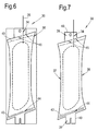
- An embodiment of the proposal is illustrated schematically in figures 6 and 7 .
- the pre-form 30 is, in the most part, prepared in the same manner as described above, and is as shown in figure 6 . However, it will be noted that at each end of the pre-form 30, in regions outside the main region of the nominal profile 36 having the most significantly reduced thickness and beyond the reference lines 43, stress-relieving openings 44, 45 are provided, which extend completely through the thickness of the pre-form 30.
- the stress-relieving opening 44 provided at the bottom end is provided in the form of an elongate and straight slot which extends generally parallel to the adjacent reference line 43.
- the slot 44 is thus located generally adjacent the datum region 39 when its peripheral edge 40 is cut from the pre-form, as illustrated in figure 7 , and is thus positioned between the datum region 39 and the main region of the nominal profile 36 of the aerofoil.
- the slot 44 is located entirely within the periphery of the pre-form 30, as illustrated in figure 7 , and thus has two closed ends, each of which is located generally adjacent a respective one of the leading edge 37 and the trailing edge 38.
- each end of the pre-form may be of substantially identical form, it is also possible for them to have different configurations.
- the upper end (in the orientation illustrated) of the pre-form illustrated in figures 6 and 7 is actually provided with a pair of openings in the form of bifurcated slots 45.
- Each bifurcated slot 45 is located on a respective side of the inflation channel 34, and has one limb which curls around the corner of the datum region, and a second limb which is positioned to substantially coincide with the end edge of the nominal profile 36 of the aerofoil.
- the two bifurcated slots 45 effectively become open through the peripheral edge of the pre-form 30.
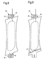
- Figure 8 illustrates a pre-form 30 following the profile cutting of the leading and trailing edges 37, 38 and the peripheral edges 40 of the datum regions 39 in which a plurality of parallel stress-relieving slots 46 are provided in each datum region 39. In this arrangement, each slot 46 is open to the periphery of the pre-form.
- Figure 9 illustrates further configurations for the stress-relieving openings.
- a pair of collinear slots 47 each of which is open to the periphery of the pre-form 30 at one end.
Landscapes
- Engineering & Computer Science (AREA)
- Mechanical Engineering (AREA)
- General Engineering & Computer Science (AREA)
- Physics & Mathematics (AREA)
- Fluid Mechanics (AREA)
- Turbine Rotor Nozzle Sealing (AREA)
- Structures Of Non-Positive Displacement Pumps (AREA)
- Wind Motors (AREA)
Claims (15)
- Procédé de formation d'un profil aérodynamique gonflé (1), le procédé comprenant les étapes consistant à : former une préforme planaire en couches (30) ; prévoir au moins une ouverture de détente des contraintes (44, 45, 46, 47) à travers la préforme ; former un fluage à haute température et gonfler la préforme (30) pour former un profil aérodynamique intermédiaire ; et retirer ensuite du matériau du profil aérodynamique intermédiaire, en incluant au moins une zone contenant la ou chaque ouverture de détente des contraintes (44, 45, 46, 47), pour former un profil aérodynamique fini.
- Procédé selon la revendication 1, incluant en outre l'étape consistant à prévoir au moins une zone de référence (39) sur la préforme (30), à utiliser dans la localisation de la préforme pendant lesdites étapes de formation d'un fluage à haute température et de gonflage, dans lequel ladite étape de formation de ladite au moins une ouverture de détente des contraintes (44, 45, 46, 47) implique de former la ou chaque ouverture dans ou de manière adjacente à une dite zone de référence (39), et ladite étape de retrait de matériau du profil aérodynamique intermédiaire implique le retrait de la ou chaque zone de référence (39).
- Procédé selon la revendication 1 ou 2, incluant en outre une étape consistant à définir sur la préforme (30) un profil nominal (36) du profil aérodynamique devant être formé.
- Procédé selon la revendication 3, dans lequel ladite étape de définition d'un profil nominal (36) implique d'usiner le profil nominal sur au moins une face dirigée vers l'extérieur de la préforme (30).
- Procédé selon la revendication 3 ou 4, laquelle est dépendante de la revendication 2, dans lequel la ou au moins une dite ouverture de détente des contraintes (44, 45, 47) est prévue à travers la préforme (30) à un emplacement situé entre une dite zone de référence (39) et une zone principale du profil nominal (36) du profil aérodynamique.
- Procédé selon l'une quelconque des revendications précédentes, dans lequel la ou au moins une dite ouverture de détente des contraintes (44,45,46,47) est prévue sous la forme d'une fente à travers la préforme (30).
- Procédé selon la revendication 6, dans lequel :la ou au moins une dite fente (44, 47) se trouve entièrement à l'intérieur de la périphérie de ladite préforme (30) ; et/oula ou au moins une dite fente (46) possède au moins une extrémité qui est ouverte sur la périphérie de la préforme (30).
- Procédé selon la revendication 6 ou 7, dans lequel :la ou au moins une dite fente (44, 46, 47) est allongé et essentiellement droite ; et/ou la ou au moins une dite fente (45) est bifurquée.
- Procédé selon l'une quelconque des revendications précédentes, comprenant en outre l'étape consistant à profiler la préforme (30) pour définir un bord d'attaque (37) et un bord de fuite (38) pour le profil aérodynamique.
- Procédé selon la revendication 9, dans lequel ladite étape de profilage implique la découpe de la préforme (30) pour définir le bord d'attaque (37) et le bord de fuite (38).
- Procédé selon la revendication 9 ou 10, laquelle dépend de la revendication 2, dans lequel ladite étape de profilage implique la découpe de la préforme (30) pour définir un bord périphérique (40) de la ou chaque zone de référence (39).
- Procédé selon l'une quelconque des revendications précédentes, dans lequel ladite étape de prévision d'une préforme planaire en couches (30) implique de souder deux revêtements extérieurs (31, 32) l'un à l'autre.
- Procédé selon la revendication 12, dans lequel :lesdits revêtements extérieurs (31,32) comprennent du titane ou de l'aluminium; et/ou lesdits revêtements extérieurs (31, 32) sont soudés par diffusion l'un à l'autre.
- Procédé selon la revendication 12 ou 13, comprenant en outre une étape consistant à appliquer un matériau de couverture dans une zone prédéfinie (33) entre les revêtements extérieurs (31, 32) avant ladite étape de soudage des revêtements l'un à l'autre, pour définir de la sorte une zone gonflable à l'intérieur de la préforme (30).
- Procédé selon l'une quelconque des revendications précédentes, dans lequel le profil aérodynamique (1) est une pale ou un aubage, en option un aubage directeur de sortie (24, 25) d'un moteur à turbine à gaz (10).
Applications Claiming Priority (1)
| Application Number | Priority Date | Filing Date | Title |
|---|---|---|---|
| GBGB1414497.6A GB201414497D0 (en) | 2014-08-15 | 2014-08-15 | A method of forming an inflated aerofoil |
Publications (3)
| Publication Number | Publication Date |
|---|---|
| EP2985089A2 EP2985089A2 (fr) | 2016-02-17 |
| EP2985089A3 EP2985089A3 (fr) | 2016-03-30 |
| EP2985089B1 true EP2985089B1 (fr) | 2016-11-23 |
Family
ID=51662479
Family Applications (1)
| Application Number | Title | Priority Date | Filing Date |
|---|---|---|---|
| EP15180393.9A Active EP2985089B1 (fr) | 2014-08-15 | 2015-08-10 | Procédé de formage d'une aube gonflée |
Country Status (3)
| Country | Link |
|---|---|
| US (1) | US9790800B2 (fr) |
| EP (1) | EP2985089B1 (fr) |
| GB (1) | GB201414497D0 (fr) |
Families Citing this family (12)
| Publication number | Priority date | Publication date | Assignee | Title |
|---|---|---|---|---|
| DE202019005660U1 (de) * | 2018-06-07 | 2021-07-12 | Abbott Diabetes Care, Inc. | Fokussierte Sterilisation und sterilisierte Teilanordnungen für Analytüberwachungssysteme |
| AU2019282729B2 (en) | 2018-06-07 | 2022-03-17 | Abbott Diabetes Care Inc. | Focused sterilization and sterilized sub-assemblies for analyte monitoring systems |
| CN109356670B (zh) * | 2018-11-16 | 2021-01-05 | 中国航发沈阳黎明航空发动机有限责任公司 | 一种空心叶片冷却导管装配干涉现象检测工具及制作方法 |
| US11014190B2 (en) | 2019-01-08 | 2021-05-25 | Raytheon Technologies Corporation | Hollow airfoil with catenary profiles |
| US10808542B2 (en) | 2019-01-11 | 2020-10-20 | Raytheon Technologies Corporation | Method of forming gas turbine engine components |
| US10995632B2 (en) | 2019-03-11 | 2021-05-04 | Raytheon Technologies Corporation | Damped airfoil for a gas turbine engine |
| US11033993B2 (en) | 2019-03-20 | 2021-06-15 | Raytheon Technologies Corporation | Method of forming gas turbine engine components |
| US11236619B2 (en) | 2019-05-07 | 2022-02-01 | Raytheon Technologies Corporation | Multi-cover gas turbine engine component |
| US11370016B2 (en) | 2019-05-23 | 2022-06-28 | Raytheon Technologies Corporation | Assembly and method of forming gas turbine engine components |
| US11174737B2 (en) | 2019-06-12 | 2021-11-16 | Raytheon Technologies Corporation | Airfoil with cover for gas turbine engine |
| US11248477B2 (en) | 2019-08-02 | 2022-02-15 | Raytheon Technologies Corporation | Hybridized airfoil for a gas turbine engine |
| US11148221B2 (en) | 2019-08-29 | 2021-10-19 | Raytheon Technologies Corporation | Method of forming gas turbine engine components |
Family Cites Families (9)
| Publication number | Priority date | Publication date | Assignee | Title |
|---|---|---|---|---|
| US5243758A (en) | 1991-12-09 | 1993-09-14 | General Electric Company | Design and processing method for manufacturing hollow airfoils (three-piece concept) |
| GB2304613B (en) * | 1995-09-02 | 1998-06-10 | Rolls Royce Plc | A method of manufacturing hollow articles by superplastic forming and diffusion bonding |
| FR2752539B1 (fr) * | 1996-08-22 | 1998-09-18 | Snecma | Procede de fabrication d'une aube creuse de turbomachine et equipement de vrillage evolutif a chaud utilise |
| US5890285A (en) | 1996-08-23 | 1999-04-06 | Mcdonnell Douglas Corporation | Method for superplastically forming a structural article |
| FR2754478B1 (fr) * | 1996-10-16 | 1998-11-20 | Snecma | Procede de fabrication d'une aube creuse de turbomachine |
| GB2360236B (en) * | 2000-03-18 | 2003-05-14 | Rolls Royce Plc | A method of manufacturing an article by diffusion bonding and superplastic forming |
| FR2871397B1 (fr) * | 2004-06-11 | 2006-09-22 | Snecma Moteurs Sa | Installation de conformation d'une aube creuse |
| GB2481000B (en) * | 2010-06-03 | 2012-08-08 | Rolls Royce Plc | A method of manufacturing an article by diffusion bonding and superplastic forming |
| GB2486695B (en) * | 2010-12-23 | 2013-02-13 | Rolls Royce Plc | A diffusion bonded and superplastically formed turbomachine blade |
-
2014
- 2014-08-15 GB GBGB1414497.6A patent/GB201414497D0/en not_active Ceased
-
2015
- 2015-08-10 EP EP15180393.9A patent/EP2985089B1/fr active Active
- 2015-08-10 US US14/822,163 patent/US9790800B2/en active Active
Non-Patent Citations (1)
| Title |
|---|
| None * |
Also Published As
| Publication number | Publication date |
|---|---|
| US20160047249A1 (en) | 2016-02-18 |
| GB201414497D0 (en) | 2014-10-01 |
| EP2985089A3 (fr) | 2016-03-30 |
| EP2985089A2 (fr) | 2016-02-17 |
| US9790800B2 (en) | 2017-10-17 |
Similar Documents
| Publication | Publication Date | Title |
|---|---|---|
| US9790800B2 (en) | Method of forming an inflated aerofoil | |
| CA2697121C (fr) | Rotor a aubes intentionnellement desaccordees de facon integrale | |
| CA2938124C (fr) | Ventilateur desynchronise | |
| US6994524B2 (en) | Hollow fan blade for gas turbine engine | |
| US7967659B2 (en) | Method of machining integral bladed rotors for a gas turbine engine | |
| US20080003096A1 (en) | High coverage cooling hole shape | |
| WO2014007939A1 (fr) | Profil de surface portante d'aube de turbine de moteur à turbine à gaz | |
| JP2017078416A (ja) | タービンブレード | |
| RU2555274C1 (ru) | Способ изготовления полой вентиляторной лопатки | |
| JP2007154874A (ja) | ガスタービンエンジンの中空ファンブレード及びその半割体の製造方法 | |
| JP2005214198A (ja) | ガスタービンエンジン用の中空ファンブレード | |
| US20110297734A1 (en) | Method of manufacturing an article by diffusion bonding and superplastic forming | |
| EP2964892B1 (fr) | Couvercles pour cavités en pales de soufflantes des aéronefs | |
| US7052238B2 (en) | Hollow fan blade for gas turbine engine | |
| US6994525B2 (en) | Hollow fan blade for gas turbine engine | |
| US20150000132A1 (en) | Apparatus and a method of shaping an edge of an aerofoil | |
| EP3350414A1 (fr) | Surface portante stratifiée pour une turbine à gaz | |
| US10415393B2 (en) | Manufacturing method | |
| EP3924176B1 (fr) | Procédé de fabrication d'une lame composite | |
| GB2530553A (en) | Fan blade and method of manufacture | |
| JP4118779B2 (ja) | 軸流タービン | |
| WO2010003513A1 (fr) | Procédé de fluage à haute température et de formage superplastique d'un article et moule pour celui-ci | |
| EP3196417A1 (fr) | Casque de face de grille pour disque de rotor à aubage intégral | |
| EP3581761A1 (fr) | Procédé de formation d'une surface portante |
Legal Events
| Date | Code | Title | Description |
|---|---|---|---|
| PUAI | Public reference made under article 153(3) epc to a published international application that has entered the european phase |
Free format text: ORIGINAL CODE: 0009012 |
|
| AK | Designated contracting states |
Kind code of ref document: A2 Designated state(s): AL AT BE BG CH CY CZ DE DK EE ES FI FR GB GR HR HU IE IS IT LI LT LU LV MC MK MT NL NO PL PT RO RS SE SI SK SM TR |
|
| AX | Request for extension of the european patent |
Extension state: BA ME |
|
| PUAL | Search report despatched |
Free format text: ORIGINAL CODE: 0009013 |
|
| AK | Designated contracting states |
Kind code of ref document: A3 Designated state(s): AL AT BE BG CH CY CZ DE DK EE ES FI FR GB GR HR HU IE IS IT LI LT LU LV MC MK MT NL NO PL PT RO RS SE SI SK SM TR |
|
| AX | Request for extension of the european patent |
Extension state: BA ME |
|
| RIC1 | Information provided on ipc code assigned before grant |
Ipc: B23P 15/04 20060101ALN20160222BHEP Ipc: B21D 26/059 20110101AFI20160222BHEP Ipc: B21D 53/78 20060101ALI20160222BHEP |
|
| 17P | Request for examination filed |
Effective date: 20160404 |
|
| RBV | Designated contracting states (corrected) |
Designated state(s): AL AT BE BG CH CY CZ DE DK EE ES FI FR GB GR HR HU IE IS IT LI LT LU LV MC MK MT NL NO PL PT RO RS SE SI SK SM TR |
|
| RIC1 | Information provided on ipc code assigned before grant |
Ipc: B23P 15/04 20060101ALN20160728BHEP Ipc: B21D 26/059 20110101AFI20160728BHEP Ipc: B21D 53/78 20060101ALI20160728BHEP |
|
| GRAP | Despatch of communication of intention to grant a patent |
Free format text: ORIGINAL CODE: EPIDOSNIGR1 |
|
| INTG | Intention to grant announced |
Effective date: 20160907 |
|
| RIN1 | Information on inventor provided before grant (corrected) |
Inventor name: QUIGLEY, DAVID |
|
| GRAS | Grant fee paid |
Free format text: ORIGINAL CODE: EPIDOSNIGR3 |
|
| GRAA | (expected) grant |
Free format text: ORIGINAL CODE: 0009210 |
|
| AK | Designated contracting states |
Kind code of ref document: B1 Designated state(s): AL AT BE BG CH CY CZ DE DK EE ES FI FR GB GR HR HU IE IS IT LI LT LU LV MC MK MT NL NO PL PT RO RS SE SI SK SM TR |
|
| REG | Reference to a national code |
Ref country code: GB Ref legal event code: FG4D |
|
| REG | Reference to a national code |
Ref country code: CH Ref legal event code: EP |
|
| REG | Reference to a national code |
Ref country code: IE Ref legal event code: FG4D |
|
| REG | Reference to a national code |
Ref country code: AT Ref legal event code: REF Ref document number: 847400 Country of ref document: AT Kind code of ref document: T Effective date: 20161215 |
|
| REG | Reference to a national code |
Ref country code: DE Ref legal event code: R096 Ref document number: 602015000799 Country of ref document: DE |
|
| PG25 | Lapsed in a contracting state [announced via postgrant information from national office to epo] |
Ref country code: LV Free format text: LAPSE BECAUSE OF FAILURE TO SUBMIT A TRANSLATION OF THE DESCRIPTION OR TO PAY THE FEE WITHIN THE PRESCRIBED TIME-LIMIT Effective date: 20161123 |
|
| REG | Reference to a national code |
Ref country code: LT Ref legal event code: MG4D |
|
| REG | Reference to a national code |
Ref country code: NL Ref legal event code: MP Effective date: 20161123 |
|
| REG | Reference to a national code |
Ref country code: AT Ref legal event code: MK05 Ref document number: 847400 Country of ref document: AT Kind code of ref document: T Effective date: 20161123 |
|
| PG25 | Lapsed in a contracting state [announced via postgrant information from national office to epo] |
Ref country code: LT Free format text: LAPSE BECAUSE OF FAILURE TO SUBMIT A TRANSLATION OF THE DESCRIPTION OR TO PAY THE FEE WITHIN THE PRESCRIBED TIME-LIMIT Effective date: 20161123 Ref country code: NL Free format text: LAPSE BECAUSE OF FAILURE TO SUBMIT A TRANSLATION OF THE DESCRIPTION OR TO PAY THE FEE WITHIN THE PRESCRIBED TIME-LIMIT Effective date: 20161123 Ref country code: SE Free format text: LAPSE BECAUSE OF FAILURE TO SUBMIT A TRANSLATION OF THE DESCRIPTION OR TO PAY THE FEE WITHIN THE PRESCRIBED TIME-LIMIT Effective date: 20161123 Ref country code: GR Free format text: LAPSE BECAUSE OF FAILURE TO SUBMIT A TRANSLATION OF THE DESCRIPTION OR TO PAY THE FEE WITHIN THE PRESCRIBED TIME-LIMIT Effective date: 20170224 Ref country code: NO Free format text: LAPSE BECAUSE OF FAILURE TO SUBMIT A TRANSLATION OF THE DESCRIPTION OR TO PAY THE FEE WITHIN THE PRESCRIBED TIME-LIMIT Effective date: 20170223 |
|
| PG25 | Lapsed in a contracting state [announced via postgrant information from national office to epo] |
Ref country code: ES Free format text: LAPSE BECAUSE OF FAILURE TO SUBMIT A TRANSLATION OF THE DESCRIPTION OR TO PAY THE FEE WITHIN THE PRESCRIBED TIME-LIMIT Effective date: 20161123 Ref country code: AT Free format text: LAPSE BECAUSE OF FAILURE TO SUBMIT A TRANSLATION OF THE DESCRIPTION OR TO PAY THE FEE WITHIN THE PRESCRIBED TIME-LIMIT Effective date: 20161123 Ref country code: PT Free format text: LAPSE BECAUSE OF FAILURE TO SUBMIT A TRANSLATION OF THE DESCRIPTION OR TO PAY THE FEE WITHIN THE PRESCRIBED TIME-LIMIT Effective date: 20170323 Ref country code: FI Free format text: LAPSE BECAUSE OF FAILURE TO SUBMIT A TRANSLATION OF THE DESCRIPTION OR TO PAY THE FEE WITHIN THE PRESCRIBED TIME-LIMIT Effective date: 20161123 Ref country code: PL Free format text: LAPSE BECAUSE OF FAILURE TO SUBMIT A TRANSLATION OF THE DESCRIPTION OR TO PAY THE FEE WITHIN THE PRESCRIBED TIME-LIMIT Effective date: 20161123 Ref country code: RS Free format text: LAPSE BECAUSE OF FAILURE TO SUBMIT A TRANSLATION OF THE DESCRIPTION OR TO PAY THE FEE WITHIN THE PRESCRIBED TIME-LIMIT Effective date: 20161123 Ref country code: HR Free format text: LAPSE BECAUSE OF FAILURE TO SUBMIT A TRANSLATION OF THE DESCRIPTION OR TO PAY THE FEE WITHIN THE PRESCRIBED TIME-LIMIT Effective date: 20161123 |
|
| PG25 | Lapsed in a contracting state [announced via postgrant information from national office to epo] |
Ref country code: DK Free format text: LAPSE BECAUSE OF FAILURE TO SUBMIT A TRANSLATION OF THE DESCRIPTION OR TO PAY THE FEE WITHIN THE PRESCRIBED TIME-LIMIT Effective date: 20161123 Ref country code: CZ Free format text: LAPSE BECAUSE OF FAILURE TO SUBMIT A TRANSLATION OF THE DESCRIPTION OR TO PAY THE FEE WITHIN THE PRESCRIBED TIME-LIMIT Effective date: 20161123 Ref country code: RO Free format text: LAPSE BECAUSE OF FAILURE TO SUBMIT A TRANSLATION OF THE DESCRIPTION OR TO PAY THE FEE WITHIN THE PRESCRIBED TIME-LIMIT Effective date: 20161123 Ref country code: EE Free format text: LAPSE BECAUSE OF FAILURE TO SUBMIT A TRANSLATION OF THE DESCRIPTION OR TO PAY THE FEE WITHIN THE PRESCRIBED TIME-LIMIT Effective date: 20161123 Ref country code: SK Free format text: LAPSE BECAUSE OF FAILURE TO SUBMIT A TRANSLATION OF THE DESCRIPTION OR TO PAY THE FEE WITHIN THE PRESCRIBED TIME-LIMIT Effective date: 20161123 |
|
| REG | Reference to a national code |
Ref country code: DE Ref legal event code: R097 Ref document number: 602015000799 Country of ref document: DE |
|
| REG | Reference to a national code |
Ref country code: FR Ref legal event code: PLFP Year of fee payment: 3 |
|
| PG25 | Lapsed in a contracting state [announced via postgrant information from national office to epo] |
Ref country code: IT Free format text: LAPSE BECAUSE OF FAILURE TO SUBMIT A TRANSLATION OF THE DESCRIPTION OR TO PAY THE FEE WITHIN THE PRESCRIBED TIME-LIMIT Effective date: 20161123 Ref country code: BE Free format text: LAPSE BECAUSE OF FAILURE TO SUBMIT A TRANSLATION OF THE DESCRIPTION OR TO PAY THE FEE WITHIN THE PRESCRIBED TIME-LIMIT Effective date: 20161123 Ref country code: SM Free format text: LAPSE BECAUSE OF FAILURE TO SUBMIT A TRANSLATION OF THE DESCRIPTION OR TO PAY THE FEE WITHIN THE PRESCRIBED TIME-LIMIT Effective date: 20161123 Ref country code: BG Free format text: LAPSE BECAUSE OF FAILURE TO SUBMIT A TRANSLATION OF THE DESCRIPTION OR TO PAY THE FEE WITHIN THE PRESCRIBED TIME-LIMIT Effective date: 20170223 |
|
| PLBE | No opposition filed within time limit |
Free format text: ORIGINAL CODE: 0009261 |
|
| STAA | Information on the status of an ep patent application or granted ep patent |
Free format text: STATUS: NO OPPOSITION FILED WITHIN TIME LIMIT |
|
| 26N | No opposition filed |
Effective date: 20170824 |
|
| PG25 | Lapsed in a contracting state [announced via postgrant information from national office to epo] |
Ref country code: SI Free format text: LAPSE BECAUSE OF FAILURE TO SUBMIT A TRANSLATION OF THE DESCRIPTION OR TO PAY THE FEE WITHIN THE PRESCRIBED TIME-LIMIT Effective date: 20161123 |
|
| PG25 | Lapsed in a contracting state [announced via postgrant information from national office to epo] |
Ref country code: MC Free format text: LAPSE BECAUSE OF FAILURE TO SUBMIT A TRANSLATION OF THE DESCRIPTION OR TO PAY THE FEE WITHIN THE PRESCRIBED TIME-LIMIT Effective date: 20161123 |
|
| REG | Reference to a national code |
Ref country code: IE Ref legal event code: MM4A |
|
| PG25 | Lapsed in a contracting state [announced via postgrant information from national office to epo] |
Ref country code: LU Free format text: LAPSE BECAUSE OF NON-PAYMENT OF DUE FEES Effective date: 20170810 |
|
| PG25 | Lapsed in a contracting state [announced via postgrant information from national office to epo] |
Ref country code: IE Free format text: LAPSE BECAUSE OF NON-PAYMENT OF DUE FEES Effective date: 20170810 |
|
| REG | Reference to a national code |
Ref country code: FR Ref legal event code: PLFP Year of fee payment: 4 |
|
| PG25 | Lapsed in a contracting state [announced via postgrant information from national office to epo] |
Ref country code: MT Free format text: LAPSE BECAUSE OF NON-PAYMENT OF DUE FEES Effective date: 20170810 |
|
| REG | Reference to a national code |
Ref country code: CH Ref legal event code: PL |
|
| PG25 | Lapsed in a contracting state [announced via postgrant information from national office to epo] |
Ref country code: LI Free format text: LAPSE BECAUSE OF NON-PAYMENT OF DUE FEES Effective date: 20180831 Ref country code: CH Free format text: LAPSE BECAUSE OF NON-PAYMENT OF DUE FEES Effective date: 20180831 |
|
| PG25 | Lapsed in a contracting state [announced via postgrant information from national office to epo] |
Ref country code: HU Free format text: LAPSE BECAUSE OF FAILURE TO SUBMIT A TRANSLATION OF THE DESCRIPTION OR TO PAY THE FEE WITHIN THE PRESCRIBED TIME-LIMIT; INVALID AB INITIO Effective date: 20150810 |
|
| PG25 | Lapsed in a contracting state [announced via postgrant information from national office to epo] |
Ref country code: CY Free format text: LAPSE BECAUSE OF FAILURE TO SUBMIT A TRANSLATION OF THE DESCRIPTION OR TO PAY THE FEE WITHIN THE PRESCRIBED TIME-LIMIT Effective date: 20161123 |
|
| PG25 | Lapsed in a contracting state [announced via postgrant information from national office to epo] |
Ref country code: MK Free format text: LAPSE BECAUSE OF FAILURE TO SUBMIT A TRANSLATION OF THE DESCRIPTION OR TO PAY THE FEE WITHIN THE PRESCRIBED TIME-LIMIT Effective date: 20161123 |
|
| PG25 | Lapsed in a contracting state [announced via postgrant information from national office to epo] |
Ref country code: TR Free format text: LAPSE BECAUSE OF FAILURE TO SUBMIT A TRANSLATION OF THE DESCRIPTION OR TO PAY THE FEE WITHIN THE PRESCRIBED TIME-LIMIT Effective date: 20161123 |
|
| PG25 | Lapsed in a contracting state [announced via postgrant information from national office to epo] |
Ref country code: AL Free format text: LAPSE BECAUSE OF FAILURE TO SUBMIT A TRANSLATION OF THE DESCRIPTION OR TO PAY THE FEE WITHIN THE PRESCRIBED TIME-LIMIT Effective date: 20161123 Ref country code: IS Free format text: LAPSE BECAUSE OF FAILURE TO SUBMIT A TRANSLATION OF THE DESCRIPTION OR TO PAY THE FEE WITHIN THE PRESCRIBED TIME-LIMIT Effective date: 20170323 |
|
| P01 | Opt-out of the competence of the unified patent court (upc) registered |
Effective date: 20230528 |
|
| PGFP | Annual fee paid to national office [announced via postgrant information from national office to epo] |
Ref country code: DE Payment date: 20250827 Year of fee payment: 11 |
|
| PGFP | Annual fee paid to national office [announced via postgrant information from national office to epo] |
Ref country code: GB Payment date: 20250826 Year of fee payment: 11 |
|
| PGFP | Annual fee paid to national office [announced via postgrant information from national office to epo] |
Ref country code: FR Payment date: 20250825 Year of fee payment: 11 |