EP2985092A1 - Outil et procédé d'usinage d'un bobinage - Google Patents
Outil et procédé d'usinage d'un bobinage Download PDFInfo
- Publication number
- EP2985092A1 EP2985092A1 EP14180597.8A EP14180597A EP2985092A1 EP 2985092 A1 EP2985092 A1 EP 2985092A1 EP 14180597 A EP14180597 A EP 14180597A EP 2985092 A1 EP2985092 A1 EP 2985092A1
- Authority
- EP
- European Patent Office
- Prior art keywords
- winding
- tool
- wheel
- hammer
- machining
- Prior art date
- Legal status (The legal status is an assumption and is not a legal conclusion. Google has not performed a legal analysis and makes no representation as to the accuracy of the status listed.)
- Withdrawn
Links
Images


Classifications
-
- H—ELECTRICITY
- H02—GENERATION; CONVERSION OR DISTRIBUTION OF ELECTRIC POWER
- H02K—DYNAMO-ELECTRIC MACHINES
- H02K15/00—Processes or apparatus specially adapted for manufacturing, assembling, maintaining or repairing of dynamo-electric machines
- H02K15/04—Processes or apparatus specially adapted for manufacturing, assembling, maintaining or repairing of dynamo-electric machines of windings prior to their mounting into the machines
-
- B—PERFORMING OPERATIONS; TRANSPORTING
- B21—MECHANICAL METAL-WORKING WITHOUT ESSENTIALLY REMOVING MATERIAL; PUNCHING METAL
- B21H—MAKING PARTICULAR METAL OBJECTS BY ROLLING, e.g. SCREWS, WHEELS, RINGS, BARRELS, BALLS
- B21H7/00—Making articles not provided for in the preceding groups, e.g. agricultural tools, dinner forks, knives, spoons
-
- B—PERFORMING OPERATIONS; TRANSPORTING
- B21—MECHANICAL METAL-WORKING WITHOUT ESSENTIALLY REMOVING MATERIAL; PUNCHING METAL
- B21J—FORGING; HAMMERING; PRESSING METAL; RIVETING; FORGE FURNACES
- B21J7/00—Hammers; Forging machines with hammers or die jaws acting by impact
-
- B—PERFORMING OPERATIONS; TRANSPORTING
- B21—MECHANICAL METAL-WORKING WITHOUT ESSENTIALLY REMOVING MATERIAL; PUNCHING METAL
- B21D—WORKING OR PROCESSING OF SHEET METAL OR METAL TUBES, RODS OR PROFILES WITHOUT ESSENTIALLY REMOVING MATERIAL; PUNCHING METAL
- B21D31/00—Other methods for working sheet metal, metal tubes, metal profiles
- B21D31/06—Deforming sheet metal, tubes or profiles by sequential impacts, e.g. hammering, beating, peen forming
-
- B—PERFORMING OPERATIONS; TRANSPORTING
- B21—MECHANICAL METAL-WORKING WITHOUT ESSENTIALLY REMOVING MATERIAL; PUNCHING METAL
- B21J—FORGING; HAMMERING; PRESSING METAL; RIVETING; FORGE FURNACES
- B21J1/00—Preparing metal stock or similar ancillary operations prior, during or post forging, e.g. heating or cooling
- B21J1/06—Heating or cooling methods or arrangements specially adapted for performing forging or pressing operations
Definitions
- the present disclosure relates to a tool for machining a winding for an electric machine, a method for machining a winding for an electric machine, and a use of a tool for machining a winding for an electric machine.
- the electric machine is in particular a rotating electric machine such as a synchronous generator to be connected to a gas or steam turbine (turbogenerator) or a synchronous generator to be connected to a hydro turbine (hydro generator) or an asynchronous generator or a synchronous or asynchronous electric motor, transformers, or also other types of electric machines.
- a rotating electric machine such as a synchronous generator to be connected to a gas or steam turbine (turbogenerator) or a synchronous generator to be connected to a hydro turbine (hydro generator) or an asynchronous generator or a synchronous or asynchronous electric motor, transformers, or also other types of electric machines.
- Windings of a coil are generally placed into notches or slots of a stator or rotor of an electric machine. Especially in the technical field of generators of high power generation these windings are prone to wear and maintenance is done for the generators. Part of this maintenance work is the replacement or repair of some of the manifold of windings, often done with welding or brazing of these parts. The maintenance work at the many windings is time consuming and expensive leading to down times of the generator not participating to the energy supply. Commonly, winding heads are connected via brazing of two half-windings being connected to a full winding thereby. Especially at the areas at which the half-windings are brazed the spaces at the winding head are narrow which leads to a need to use the available space in an efficient way.
- An object of the invention is to provide a method and a tool to machine windings for an electric machine suitable for a space sensitive use at a winding head. Another object is to provide a fast and efficient method to machine windings. The object is solved with the features of the independent claims. Further examples of the invention are disclosed in the dependent claims.
- Fig. 1 shows a perspective view to the end of illustrating the principle of the tool 1 and the corresponding method. Shown are three parts of conductor bars or copper windings 12 next to each other.
- the windings 12 are shown in a cross-section and have usually a length of several metres.
- the windings 12 hereby are windings 12 of a rotor of a generator to produce power in the range of usually megawatts.
- the rotor windings 12 have hollow profiles which are provided as ducts for a cooling medium to flow through in operation of the generator.
- the windings 12 are hollow conductors consequently. In the Figs the windings 12 are removed from the notches or slots of the rotor core for maintenance reasons and are thereby easily accessible.
- the height h of the left winding 12 hereby the size from below to above marked with an arrow, is lower than the height h of the windings 12 at the right side.
- the left winding 12 is machined by the tool 1 and thereby has a reduced height h.
- the right winding 12 is placed in a backing 11 securely holding the winding 12.
- a plate 15 finishes the backing 11 and serves as a bearing for the winding 12.
- the backing 11 rests on a feet 13 at the ground.
- a wheel 4 is shown above the right winding 12, whereas the wheel 4 is a part of a first example of the tool 1 to be described fully below.
- the wheel 4 can be made from a high tensile steel or a composite material or from a different material except aluminium or copper.
- the wheel 4 is designed with an inner part having a smaller diameter than the outer part.
- the wheel 4 contains two outer discs and a shaft 3 with a smaller diameter connecting the discs, similar in shape to a cable drum.
- the wheel 4 is part of the tool 1, driven and operated as is described below.
- the winding 12 can be fixed at the backing 11 or alternatively the winding 12 can be slipped along the backing 11. When the winding 12 is fixed and does not move the tool 1 is moved along the length of the winding 12 engaging the upper side of the winding 12. In the alternative, when the winding 12 moves in an axial direction to the centre line the tool 1 does not have to move along the winding 12.
- Fig. 2 shows a perspective view of an example of a part of a winding 12 which is partly machined by a tool 1 according to the invention.
- the winding 12 is machined and has a reduced height h compared to the height of the winding 12 right from the bending. It is visible that the right part of the winding 12 has two hollow chambers and the left machined part of the winding 12 has only one hollow chamber. This means the partition wall within the winding 12 between the two hollow chambers is removed after machining.
- One chamber is completely closed by application of heat by a heat source 20 and pressure to the small face or both small faces of the winding 12.
- a predefined temperature profile across the conductor winding 12 with a higher temperature on the face of the winding 12 to be shaped avoids undesired side effects.
- the bending of the winding 12 to an extend of approximately 90° has the purpose to use one end of the winding 12 as a so called end winding projecting from a notch or slot in the stator outwards with a specific angle.
- the bending can be achieved by different methods. One of these methods is to exert a pressure by the tool 1 and to conduct the tool 1 along a corresponding curve at the upper side in Fig. 2 with a specific bending degree.
- the winding 12 is in this alternative not only reduced in height h but also the shape of the winding 12 is changed to create an angle as shown in Fig. 2 .
- Another method is to bend the winding 12 with a different bending device of the common state of the art.
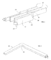
- Fig. 3 shows a perspective view of supports 10, 10' with an integrated counterpart 6 connected in one piece.
- the supports 10, 10' and the counterpart 6 form a u-shape to house the winding 12.
- the view of Fig. 3 is skipped for 90° to the right, the foot 13 is correspondingly at the left face of the counterpart 6.
- the plate 15 is fixed by screws to each support 10, 10' and bridges the supports 10, 10'.
- the plate 15 has approximately the length of the distance of the outer faces of the two supports 10, 10', as can be seen in Fig. 3 .
- the plate 15 is suitable for bearing the winding 12 between the supports 10, 10'.
- Fig. 4 shows a perspective view similar to Fig. 3 with the supports 10, 10' and the counterpart 6 rotated and the plate 15 and the winding 12 removed. Visible is the rectangular recess formed by the supports 10, 10' below and above and the counterpart 6 behind to include the winding 12. There is a rectangular channel 7 formed in the counterpart 6 which is smaller than the distance between the inner faces of the supports 10, 10'.
- Fig. 5 illustrates a view similar to Fig. 4 , whereby the plate 15 is attached to the supports 10, 10' and counterpart 6 at the left side in this skipped view.
- the configuration of the supports 10 10' with an attached plate 15 is the same as the configuration of Fig. 3 .
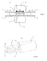
- Fig. 6 is a schematic side view of a further example of a tool 1 according to the invention.
- the supports 10, 10' are designed as rollers in this example. Operating the rollers and rotating the rollers transports the winding 12 in the direction into the image plane.
- the tool 1 can keep the position in the direction into the image plane in this example.
- the supports 10, 10' are adjusted to the upper and lower end of the winding 12 which is fixed between the supports 10, 10'.
- the supports 10, 10' have a cylindrical shape and are adapted to fix the winding 12 between them.
- the winding 12 is shown in a cross-section and has usually a length of several metres.
- the winding 12 hereby is a winding 12 of a rotor of a generator to produce power in the range of usually megawatts.
- the rotor winding 12 has two hollow profiles which are provided as ducts for a cooling medium to flow through in operation of the generator.
- the winding 12 is removed from the notches of the rotor core for maintenance reasons and is therefore easily accessible.
- the tool 1 is brought adjacent to the winding 12 which is shown in a schematic way comprising the rotating wheel 4 which has said arms 5, 5' to support the wheel 4.
- the arms 5 are connected via an axis projecting through a hole or bushing in the wheel 4.
- the rotary bushing can be supplied by graphite powder or special alloys (e.g. Graphalloy) providing a long service time before maintenance is necessary.
- the wheel 4 can be attached to a ball 8 as a suspension as is described below in more detail.
- the axis of the movable wheel 4 is driven by an electric motor (not shown) comprised by the tool 1.
- the electric motor and the ends of the arms 5, 5' far from the rotatable wheel 4 are accommodated in a housing 2, as can be seen in Figs 8 , 9 .
- the material of the rotating wheel 4 can be high strength, high tensile, high temperature steel. Alternatively, the material of the rotating wheel 4 can be a composite material.
- the breadth of the rotatable wheel 4 is adjusted to fit between the supports 10, 10' without touching the supports 10, 10' in operation and impairing the running of the movable wheel 4 and damaging it. As is shown in Fig. 6 the counterpart 6 is positioned abut on the winding 12 at the opposite side of the rotating wheel 4.
- the counterpart 6 is separate from the supports 10, 10' in this example, not fabricated one-piece with the supports 10, 10'.
- the wheel 4 exerts a force at the winding 12 and by this force the shape of the winding 12 is changed, especially the height h of the winding 12 is reduced.
- the height h is the expansion from left to right correspondingly, indicated by the arrow.
- the breadth of the winding 12 is not changed as the supports 10, 10' exert forces from the lower and upper side in this view.
- the reduction in height h is especially useful as the space for housing the winding 12 in the generator is limited and to be kept small. This is especially important in repair works at the generator in which parts of the windings 12 or half-windings are replaced, the so called rewinding of the generator.
- the method does not remove any material from the winding 12. This means the volume of the winding 12 is reduced without a loss of material.
- the movable wheel 4 of the tool 1 is designed with an imbalance thus performing an oscillation of the rotating wheel 4. By this means the force is applied to the winding 12 as a kind of hammering with low amplitude. This means the wheel 4 conducts a bidirectional movement in the axial direction of the tool, indicated by the double sided arrow at the left.
- This hammering movement may be the only movement the wheel 4 conducts.
- the wheel 4 additionally conducts a rotating movement around its axis.
- the third application is that the wheel 4 only conducts a rotating movement without a hammering or bidirectional movement.
- heat and pressure is applied by the tool 1.
- the tool 1 comprises a heat source 20, described under Fig. 9 .
- the temperature range of this heat application can be between 250°C to 900°C, preferably 500°C.
- the heat source 20 can be integrated in the tool 1 and can be based on high frequency induction, high current resistive or direct (short) flame, e.g. by burning of fuel in a tank comprised by the tool 1.
- the tool 1 comprises a chemical tank to apply a chemical substance to the winding 12.
- the heat source 20 can also comprise a plasma torch.
- the heat source 6 is a separate part of the tool 1.
- an anti-friction agent By application of an anti-friction agent the sliding of the surface of the rotating wheel 4 along the surface of the winding 12 is facilitated.
- rills or a template is engraved or imprinted into the wheel 4 or roller to the end of imprinting the corresponding form or figure of the rills or template into the surface of the conductor winding 12. To this end of imprinting the winding 12 the tool 1 is designed in the hammering mode described above with a fixed wheel 4.
- the imprinting of rills or a template leading to an uneven and structured surface can be useful for example to enlarge the cooling surface of the conductor winding 12 and thus to improve the cooling properties.
- Another aspect of this feature is to imprint rills into the winding 12 which are suitable to engage to spacers (not shown). These spacers are commonly placed between windings 12 to create a distance space between the windings 12. Applying these rills for the spacers improves the mechanical properties of the windings 12 with attached spacers.
- the tool 1 is in an example equipped with at least one sensor suitable for measuring the speed of the movable wheel 4.
- An optional microcontroller is comprised by the tool 1 to control the speed measured by the sensor.
- the speed control of the tool 1 improves the quality and speediness of the method of machining the winding 12.
- the tool 1 can be manufactured as a portable or handheld device. To this end the tool 1 has a grip projecting from the housing 2 by which an operator can carry and handle the tool 1 with both hands. As a handheld tool 1 the service scope is extended and the tool 1 is employed in a flexible way. Alternatively, the tool 1 is part of a robotized automation system. As part of this the tool 1 is embedded in a frame resting on the bottom with rolls to move the system to the place of work. Designed as an automation system the operator has not to carry the tool 1 but only to operate the automation system.
- Fig. 7 shows a schematic side view similar to Fig. 6 with a second rotatable wheel 4' engaging the winding 12 from the opposite side of the winding 12 than the first rotating wheel 4 engaging from the left.
- the second rotatable wheel 4' having also arms 5' supporting the second rotatable wheel 4' and replacing the counterpart 6 in the first example under Fig. 1 .
- two equal tools 1 are provided accordingly which shape the winding 12 in between from both sides.
- Another example for achieving a variable sweep curve for the compressed hollow conductor, namely the winding 12, is to apply at least two rotating counter wheels 4' next to each other instead of one shown in Fig. 7 .
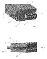
- Fig. 8 shows a perspective view of an example of the tool 1 which can be handled manually by an operator.
- the tool 1 comprises a housing 2 to accommodate an electric motor with a power in the range of several kilowatts.
- the motor drives via a shaft 3 and the arms 5, 5' a ball 8 made from ceramic in this example.
- the wheel 4 is hereby securely fixed to the ceramic ball 8 and thus follows the movement of the ceramic ball 8.
- the movement of the wheel 4 is corresponding to the other examples a bidirectional movement and/ or a rotational movement.
- Fig. 9 illustrates a perspective view similar to Fig. 8 showing the tool 1 in an operation mode.
- the tool 1 travels along the small face of a hollow conductor, a part of the winding 12.
- the wheel 4 of the tool 1 is moved as described.
- Above the winding 12 the heat source 20 is mounted to apply heat to the winding 12.
- the application of heat by the heat source 20 and pressure by the driven wheel 4 leads to an even deformation of the rectangular winding 12, such that the height h is reduced essentially without deforming the other faces of the winding 12.
- the height h is the dimension from left to right.
- a substantial reduction of the volume of the winding 12 is achieved to fulfil the requirements of little space available in big size electric machines.
- Fig. 10 shows a schematic side view of a tool 1 according to the example of Fig. 9 .
- the wheel 4 has an opening in the middle which has a slightly smaller diameter than the diameter of the ball 8.
- the wheel 4 further is longitudinally divided in two sections.
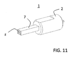
- Fig. 11 shows a schematic perspective view of an alternative example of the inventive tool 1.
- the tool 1 hereby has a hammer 7 serving for engaging to the winding 12.
- the machining function is fulfilled by the hammer 7.
- the hammer 7 has a rectangular cross-section in this example.
- the hammer 7 conducts a bidirectional movement in the axial direction of the tool 1, no rotational movement is conducted hereby.
- the hammer 7 is at least at the front side made from a high tensile steel or a composite material or from a different material.
- the hammer 7 is designed at the far front end plane with a structure of rills embossed or stamped into the plane.
- Fig. 11 three elevations are shown creating a rill between each elevation.
- the surface structure s of the hammer 7 transfers the rills or templates into the winding 12.
- the surface structure of the winding 12 is modified correspondingly at the face at which the tool 1 is applied.
- a heat source 20 is applied correspondingly to apply heat to the winding 12.
- the imprinting of rills or a template leading to a structured surface of the winding 12 can be useful for example to enlarge the cooling surface of the conductor winding 12 and thus to improve the cooling properties.
- Another aspect of this feature is to imprint rills into the winding 12 which are suitable to engage to spacers (not shown). These spacers are used to ensure a certain distance between several adjacent windings 12.
- the tool 1 achieves as a main issue in connection with retrofit the increase of the power to volume ratio by shortening the end regions of the winding 12.
- a reduction of the bending radii of the windings 12 is achieved to reduce the volume and to make the electric machine or rotor more compact.
- the invention allows to avoid any fused parts or removal of material from the winding 12.
Landscapes
- Engineering & Computer Science (AREA)
- Mechanical Engineering (AREA)
- Manufacturing & Machinery (AREA)
- Power Engineering (AREA)
- Life Sciences & Earth Sciences (AREA)
- Agronomy & Crop Science (AREA)
- Manufacture Of Motors, Generators (AREA)
Priority Applications (4)
| Application Number | Priority Date | Filing Date | Title |
|---|---|---|---|
| EP14180597.8A EP2985092A1 (fr) | 2014-08-12 | 2014-08-12 | Outil et procédé d'usinage d'un bobinage |
| US14/807,935 US20160049852A1 (en) | 2014-08-12 | 2015-07-24 | Tool and method for maching a winding |
| CN201510491699.0A CN105375702A (zh) | 2014-08-12 | 2015-08-12 | 用于加工绕组的工具和方法 |
| US15/018,206 US20160156146A1 (en) | 2014-08-12 | 2016-02-08 | Tool and method for shaping a hollow conductor bar |
Applications Claiming Priority (1)
| Application Number | Priority Date | Filing Date | Title |
|---|---|---|---|
| EP14180597.8A EP2985092A1 (fr) | 2014-08-12 | 2014-08-12 | Outil et procédé d'usinage d'un bobinage |
Publications (1)
| Publication Number | Publication Date |
|---|---|
| EP2985092A1 true EP2985092A1 (fr) | 2016-02-17 |
Family
ID=51398485
Family Applications (1)
| Application Number | Title | Priority Date | Filing Date |
|---|---|---|---|
| EP14180597.8A Withdrawn EP2985092A1 (fr) | 2014-08-12 | 2014-08-12 | Outil et procédé d'usinage d'un bobinage |
Country Status (3)
| Country | Link |
|---|---|
| US (1) | US20160049852A1 (fr) |
| EP (1) | EP2985092A1 (fr) |
| CN (1) | CN105375702A (fr) |
Citations (8)
| Publication number | Priority date | Publication date | Assignee | Title |
|---|---|---|---|---|
| GB1050683A (fr) * | 1900-01-01 | |||
| GB218840A (en) * | 1923-07-07 | 1924-07-17 | Nicolaus Meurer | Improvements in and relating to pneumatic hammers |
| US2242204A (en) * | 1939-02-13 | 1941-05-13 | Homer R Kennedy | Sheet metal forming machine |
| US2799026A (en) * | 1954-12-01 | 1957-07-16 | Maxwell John | Hammer and torch |
| GB1501623A (en) * | 1974-02-15 | 1978-02-22 | Int Harvester Co | Metal shaping processes |
| WO1982001835A1 (fr) * | 1980-12-03 | 1982-06-10 | Philip G Byrd | Machine d'aplatissement du cordon de soudure interne de tubes soudes |
| JPS58209404A (ja) * | 1982-05-31 | 1983-12-06 | Mitsubishi Steel Mfg Co Ltd | テ−パ圧延加工装置 |
| GB2154477A (en) * | 1984-02-18 | 1985-09-11 | Lucas Ind Plc | Manufacture of armature winding conductors |
Family Cites Families (7)
| Publication number | Priority date | Publication date | Assignee | Title |
|---|---|---|---|---|
| USRE26788E (en) * | 1969-01-13 | 1970-02-10 | Motor stator stack op bonded laminations with less bonding material at bolt hole regions | |
| GB1501622A (en) * | 1972-02-16 | 1978-02-22 | Int Harvester Co | Metal shaping processes |
| US4559698A (en) * | 1983-12-21 | 1985-12-24 | General Electric Company | Method of treating a loose wound core, method of fabricating a loose wound core, and method of operating apparatus |
| US4485126A (en) * | 1983-12-21 | 1984-11-27 | General Electric Company | Method of treating winding means of dynamoelectric machine core |
| JP3474769B2 (ja) * | 1998-04-08 | 2003-12-08 | 三菱電機株式会社 | 電機子コイル導体とその製造方法 |
| CN1311960C (zh) * | 2004-02-26 | 2007-04-25 | 甘国工 | 连续生产正交复合双向抗拉有热封层筒形膜的方法及装置 |
| CN100355554C (zh) * | 2004-10-13 | 2007-12-19 | 甘国工 | 连续生产正交复合双向抗拉有热封层筒形膜的方法及装置 |
-
2014
- 2014-08-12 EP EP14180597.8A patent/EP2985092A1/fr not_active Withdrawn
-
2015
- 2015-07-24 US US14/807,935 patent/US20160049852A1/en not_active Abandoned
- 2015-08-12 CN CN201510491699.0A patent/CN105375702A/zh active Pending
Patent Citations (8)
| Publication number | Priority date | Publication date | Assignee | Title |
|---|---|---|---|---|
| GB1050683A (fr) * | 1900-01-01 | |||
| GB218840A (en) * | 1923-07-07 | 1924-07-17 | Nicolaus Meurer | Improvements in and relating to pneumatic hammers |
| US2242204A (en) * | 1939-02-13 | 1941-05-13 | Homer R Kennedy | Sheet metal forming machine |
| US2799026A (en) * | 1954-12-01 | 1957-07-16 | Maxwell John | Hammer and torch |
| GB1501623A (en) * | 1974-02-15 | 1978-02-22 | Int Harvester Co | Metal shaping processes |
| WO1982001835A1 (fr) * | 1980-12-03 | 1982-06-10 | Philip G Byrd | Machine d'aplatissement du cordon de soudure interne de tubes soudes |
| JPS58209404A (ja) * | 1982-05-31 | 1983-12-06 | Mitsubishi Steel Mfg Co Ltd | テ−パ圧延加工装置 |
| GB2154477A (en) * | 1984-02-18 | 1985-09-11 | Lucas Ind Plc | Manufacture of armature winding conductors |
Also Published As
| Publication number | Publication date |
|---|---|
| US20160049852A1 (en) | 2016-02-18 |
| CN105375702A (zh) | 2016-03-02 |
Similar Documents
| Publication | Publication Date | Title |
|---|---|---|
| CN103563223B (zh) | 用于通过弯曲制造电动发电机的磁芯的线圈部件的设备和方法 | |
| US20160156146A1 (en) | Tool and method for shaping a hollow conductor bar | |
| JPWO2013190860A1 (ja) | ステータ製造装置及びステータ製造方法 | |
| JP2010158698A (ja) | 曲げ加工装置及び曲げ加工機 | |
| KR102040911B1 (ko) | 모터 보수용 분해장치 및 이를 이용한 모터 분해방법 | |
| KR102010299B1 (ko) | 회전전기기계의 헤어핀 정렬장치 | |
| DE50306008D1 (de) | Vorrichtung zum Betreiben eines Magnetfahrzeugs | |
| JP2014528228A (ja) | 電気機械エネルギー変換器のステータとロータとの間の空隙を維持する機械組立体 | |
| CN109617335B (zh) | 电机定子线圈的卧式整形机 | |
| JP2009038965A (ja) | ウェッジまたはスライドの駆動用工具 | |
| US20160049852A1 (en) | Tool and method for maching a winding | |
| JP5302878B2 (ja) | 電磁鋼板の溝加工装置及び溝加工方法 | |
| KR20120047060A (ko) | 주축의 강성 측정장치 | |
| CN104801894A (zh) | 用于母线管焊接的焊枪位置调节装置 | |
| JP2012218145A (ja) | コイルカッティングツール及びその方法 | |
| KR100949734B1 (ko) | 교정기용 교정롤 세팅장치 | |
| CN204145233U (zh) | 电机转子的热态动平衡辅助机构及热态动平衡测量装置 | |
| KR102439457B1 (ko) | 축 열박음을 위한 공기압축기 에어 앤드용 스크류 로터 가열장치 | |
| CN110814129A (zh) | 一种新型弯折装置 | |
| CN102974657B (zh) | 一种卷制机的材料轴 | |
| JP4808256B2 (ja) | 発電機及びそれを用いたガスタービン発電設備 | |
| CN103447751B (zh) | 一种螺旋地桩螺旋片机械盘绕装置 | |
| JP2011200996A (ja) | 表面粗面化処理装置および表面粗面化処理方法 | |
| CN205490029U (zh) | 一种电机定子扩孔装置 | |
| US2205783A (en) | Method and apparatus for straightening housings |
Legal Events
| Date | Code | Title | Description |
|---|---|---|---|
| PUAI | Public reference made under article 153(3) epc to a published international application that has entered the european phase |
Free format text: ORIGINAL CODE: 0009012 |
|
| AK | Designated contracting states |
Kind code of ref document: A1 Designated state(s): AL AT BE BG CH CY CZ DE DK EE ES FI FR GB GR HR HU IE IS IT LI LT LU LV MC MK MT NL NO PL PT RO RS SE SI SK SM TR |
|
| AX | Request for extension of the european patent |
Extension state: BA ME |
|
| RAP1 | Party data changed (applicant data changed or rights of an application transferred) |
Owner name: GENERAL ELECTRIC TECHNOLOGY GMBH |
|
| 17P | Request for examination filed |
Effective date: 20160817 |
|
| RBV | Designated contracting states (corrected) |
Designated state(s): AL AT BE BG CH CY CZ DE DK EE ES FI FR GB GR HR HU IE IS IT LI LT LU LV MC MK MT NL NO PL PT RO RS SE SI SK SM TR |
|
| STAA | Information on the status of an ep patent application or granted ep patent |
Free format text: STATUS: THE APPLICATION IS DEEMED TO BE WITHDRAWN |
|
| 18D | Application deemed to be withdrawn |
Effective date: 20190301 |