EP2985174A1 - Sitzschiebevorrichtung für ein fahrzeug - Google Patents
Sitzschiebevorrichtung für ein fahrzeug Download PDFInfo
- Publication number
- EP2985174A1 EP2985174A1 EP15180369.9A EP15180369A EP2985174A1 EP 2985174 A1 EP2985174 A1 EP 2985174A1 EP 15180369 A EP15180369 A EP 15180369A EP 2985174 A1 EP2985174 A1 EP 2985174A1
- Authority
- EP
- European Patent Office
- Prior art keywords
- column part
- rail
- upside
- downside
- friction reducing
- Prior art date
- Legal status (The legal status is an assumption and is not a legal conclusion. Google has not performed a legal analysis and makes no representation as to the accuracy of the status listed.)
- Granted
Links
Images





Classifications
-
- B—PERFORMING OPERATIONS; TRANSPORTING
- B60—VEHICLES IN GENERAL
- B60N—SEATS SPECIALLY ADAPTED FOR VEHICLES; VEHICLE PASSENGER ACCOMMODATION NOT OTHERWISE PROVIDED FOR
- B60N2/00—Seats specially adapted for vehicles; Arrangement or mounting of seats in vehicles
- B60N2/02—Seats specially adapted for vehicles; Arrangement or mounting of seats in vehicles the seat or part thereof being movable, e.g. adjustable
- B60N2/04—Seats specially adapted for vehicles; Arrangement or mounting of seats in vehicles the seat or part thereof being movable, e.g. adjustable the whole seat being movable
- B60N2/06—Seats specially adapted for vehicles; Arrangement or mounting of seats in vehicles the seat or part thereof being movable, e.g. adjustable the whole seat being movable slidable
- B60N2/07—Slide construction
- B60N2/0722—Constructive details
-
- B—PERFORMING OPERATIONS; TRANSPORTING
- B60—VEHICLES IN GENERAL
- B60N—SEATS SPECIALLY ADAPTED FOR VEHICLES; VEHICLE PASSENGER ACCOMMODATION NOT OTHERWISE PROVIDED FOR
- B60N2/00—Seats specially adapted for vehicles; Arrangement or mounting of seats in vehicles
- B60N2/02—Seats specially adapted for vehicles; Arrangement or mounting of seats in vehicles the seat or part thereof being movable, e.g. adjustable
- B60N2/04—Seats specially adapted for vehicles; Arrangement or mounting of seats in vehicles the seat or part thereof being movable, e.g. adjustable the whole seat being movable
- B60N2/06—Seats specially adapted for vehicles; Arrangement or mounting of seats in vehicles the seat or part thereof being movable, e.g. adjustable the whole seat being movable slidable
- B60N2/067—Seats specially adapted for vehicles; Arrangement or mounting of seats in vehicles the seat or part thereof being movable, e.g. adjustable the whole seat being movable slidable by linear actuators, e.g. linear screw mechanisms
-
- B—PERFORMING OPERATIONS; TRANSPORTING
- B60—VEHICLES IN GENERAL
- B60N—SEATS SPECIALLY ADAPTED FOR VEHICLES; VEHICLE PASSENGER ACCOMMODATION NOT OTHERWISE PROVIDED FOR
- B60N2/00—Seats specially adapted for vehicles; Arrangement or mounting of seats in vehicles
- B60N2/02—Seats specially adapted for vehicles; Arrangement or mounting of seats in vehicles the seat or part thereof being movable, e.g. adjustable
- B60N2/04—Seats specially adapted for vehicles; Arrangement or mounting of seats in vehicles the seat or part thereof being movable, e.g. adjustable the whole seat being movable
- B60N2/06—Seats specially adapted for vehicles; Arrangement or mounting of seats in vehicles the seat or part thereof being movable, e.g. adjustable the whole seat being movable slidable
- B60N2/07—Slide construction
-
- B—PERFORMING OPERATIONS; TRANSPORTING
- B60—VEHICLES IN GENERAL
- B60N—SEATS SPECIALLY ADAPTED FOR VEHICLES; VEHICLE PASSENGER ACCOMMODATION NOT OTHERWISE PROVIDED FOR
- B60N2/00—Seats specially adapted for vehicles; Arrangement or mounting of seats in vehicles
- B60N2/02—Seats specially adapted for vehicles; Arrangement or mounting of seats in vehicles the seat or part thereof being movable, e.g. adjustable
- B60N2/04—Seats specially adapted for vehicles; Arrangement or mounting of seats in vehicles the seat or part thereof being movable, e.g. adjustable the whole seat being movable
- B60N2/06—Seats specially adapted for vehicles; Arrangement or mounting of seats in vehicles the seat or part thereof being movable, e.g. adjustable the whole seat being movable slidable
- B60N2/07—Slide construction
- B60N2/0702—Slide construction characterised by its cross-section
- B60N2/0705—Slide construction characterised by its cross-section omega-shaped
-
- B—PERFORMING OPERATIONS; TRANSPORTING
- B60—VEHICLES IN GENERAL
- B60N—SEATS SPECIALLY ADAPTED FOR VEHICLES; VEHICLE PASSENGER ACCOMMODATION NOT OTHERWISE PROVIDED FOR
- B60N2/00—Seats specially adapted for vehicles; Arrangement or mounting of seats in vehicles
- B60N2/02—Seats specially adapted for vehicles; Arrangement or mounting of seats in vehicles the seat or part thereof being movable, e.g. adjustable
- B60N2/04—Seats specially adapted for vehicles; Arrangement or mounting of seats in vehicles the seat or part thereof being movable, e.g. adjustable the whole seat being movable
- B60N2/06—Seats specially adapted for vehicles; Arrangement or mounting of seats in vehicles the seat or part thereof being movable, e.g. adjustable the whole seat being movable slidable
- B60N2/07—Slide construction
- B60N2/0702—Slide construction characterised by its cross-section
- B60N2/0715—C or U-shaped
-
- B—PERFORMING OPERATIONS; TRANSPORTING
- B60—VEHICLES IN GENERAL
- B60N—SEATS SPECIALLY ADAPTED FOR VEHICLES; VEHICLE PASSENGER ACCOMMODATION NOT OTHERWISE PROVIDED FOR
- B60N2/00—Seats specially adapted for vehicles; Arrangement or mounting of seats in vehicles
- B60N2/02—Seats specially adapted for vehicles; Arrangement or mounting of seats in vehicles the seat or part thereof being movable, e.g. adjustable
- B60N2/04—Seats specially adapted for vehicles; Arrangement or mounting of seats in vehicles the seat or part thereof being movable, e.g. adjustable the whole seat being movable
- B60N2/06—Seats specially adapted for vehicles; Arrangement or mounting of seats in vehicles the seat or part thereof being movable, e.g. adjustable the whole seat being movable slidable
- B60N2/07—Slide construction
- B60N2/075—Slide construction roller-less
Definitions
- the present application relates to a seat slide device for a vehicle, which enables a seat to be moved in a front-rear direction of the vehicle and fixed in a desired position by a seating passenger.
- each of the manual seat slide device and the electrical seat slide device includes a lower rail fixed to a vehicle body, an upper rail fixed on an under face of a seat and adapted so as to be movable with respect to the lower rail in the longitudinal direction and, a friction reducing member for reducing friction between the lower rail and the upper rail.
- a resinous shown in JP 2006-168589 A or guide balls rotatably supported by a retainer shown in JP 2010-105618 A is mainly employed as the friction reducing member.
- an object of the present application is to provide a seat slide device for a vehicle, which can reduce the types of upper and lower rails to be managed since the friction reducing members different in constitution are compatible with each other.
- a seat slide device for a vehicle includes a lower rail, an upper rail, and a friction reducing member.
- the lower rail includes a lower bottom wall having a rectangular shape extending in a front-rear direction of the vehicle, a pair of lower sidewalls standing from both edges of the lower bottom wall in a width direction of the vehicle upwardly through lower downside circular parts, a pair of lower top walls each extending from an upper edge of each of the lower sidewalls toward the opposing lower sidewall through a lower upside circular part formed by a circular surface, substantially in parallel with the lower bottom wall and lower inner walls suspending from inner edges of the lower top walls downwardly.
- the upper rail includes an upper top wall having a rectangular shape extending in the front-rear direction of the vehicle, a pair of upper sidewalls suspending from both edges of the upper top wall in the width direction of the vehicle downwardly, a pair of upper downside inclined walls standing from lower edges of the upper sidewall obliquely upward and outward and a pair of upper upside inclined walls standing from top edges of the upper downside inclined walls toward the upper sidewalls obliquely upward, wherein the upper downside inclined walls and the upper upside inclined walls are arranged so as to be movable in the lower rail along the front-rear direction of the vehicle under condition that the upper downside inclined walls face the lower downside circular parts, while the upper upside inclined walls are facing the lower upside circular parts.
- the friction reducing member is arranged between the lower rail and the upper rail.
- the friction reducing member includes one or more sliding contact members.
- Each of the sliding contact members includes a lower column part consisting of a columnar member arranged between the lower downside circular part and the upper downside inclined wall along a longitudinal direction, an upper column part consisting of a columnar member arranged between the lower upside circular part and the upper upside inclined wall along the longitudinal direction and one or more connection parts connecting the upper column part with the lower column part.
- the sliding contact member as the friction reducing member can be employed for the upper rail and the lower rail corresponding to guide balls. Consequently, since the friction reducing members different in constitution have compatibility, it is possible to reduce the types of the lower rail and the upper rail to be managed.
- the friction reducing member may be formed, between the lower column part and the upper column part, with a slit in the form of an elongated hole along the longitudinal direction.
- the lower column part and the upper column part bend in the region of the slit, so that variation in the clearance between the lower downside circular part and the lower upside circular part of the lower rail is absorbed. Thus, it is possible to further reduce the sliding resistance.
- the slit may be formed so as to be the elongated hole by at least a pair of the connection parts connecting the upper column part with the lower column part.
- both column parts become possible to be deflected, allowing the interval between both column parts to be adjusted.
- the lower column part may be formed, at its region abutting on the upper downside inclined wall, with a plurality of first friction reducing dents which are dented so as to depart from the upper downside inclined wall, at predetermined intervals along the longitudinal direction
- the upper column part may be formed, at its region abutting on the upper upside inclined wall, with a plurality of second friction reducing dents which are dented so as to depart from the upper upside inclined wall, at predetermined intervals along the longitudinal direction.
- the contact area between the sliding contact member and the upper rail can be reduced. As a result, it is possible to promote the reduction of the sliding resistance.
- the friction reducing member may be formed with a length less than a half of the dimension of the lower rail in the longitudinal direction and also arranged in front and rear pairs in the longitudinal direction of the lower rail.
- the friction reducing member may be provided with a fitting part and a restriction protrusion both protruding toward the lower sidewall, and the lower sidewall may be provided with a through-hole fittable to the fitting part and a restriction hole fittable to the restriction protrusion.
- the fitting part may include an L-shaped protrusion extending in the longitudinal direction of the lower rail; the through-hole may be a hole which penetrates through the lower sidewall and into which the fitting part can be fittingly inserted; and by sliding the friction reducing member with the fitting part inserted into the through-hole, in the longitudinal direction of the lower rail, the L-shaped fitting part may be engaged with a marginal part of the through-hole, while the restriction protrusion is fittably opposed to the restriction hole.
- the restriction protrusion and the fitting part are set so that their dimensions in the longitudinal direction of the lower rail are substantially equal to each other.
- the radius of the lower column part is set smaller than the curvature radius of the lower downside circular part, and a contact point between the lower downside circular part and the lower column part, a center of the lower column part and a contact point between the lower column part and the upper downside inclined wall are positioned in alignment with each other.
- the radius of the upper column part is set smaller than the curvature radius of the lower upside circular part, and a contact point between the lower upside circular part and the upper column part, a center of the upper column part and a contact point between the upper column part and the upper upside inclined wall are positioned in alignment with each other. It is desirable that a connection point between the connection part and the lower column part and a connection point between the connection part and the upper column part are distant from the lower sidewall.
- the connection point between the connection part and the lower column part and the connection point between the connection part and the upper column part are distant from the lower sidewall, variation in the clearance between the lower rail and the upper rail can be absorbed since the connection points are bent and deformed.
- the upper rail can slide in the lower rail without rattling and with stability.
- the connection point between the connection part and the lower column part and the connection point between the connection part and the upper column part are distant from the lower sidewall, the lower column part and the upper column part can contact the lower downside circular part and the lower upside circular part at only the contact points, respectively. Therefore, even if the radial dimensions of these column parts and circular parts vary, the positions of the above contact points would be stabilized to allow the above-mentioned effect to be realized.
- the upper column part may be formed, behind its region abutting on the upper upside inclined wall, with an elastic adjustment part consisting of a recess.
- the region of the upper column part abutting on the upper upside inclined wall becomes possible to be deformed elastically. Then, since the upper column part is elastically deformed in accordance with the clearance between the upper rail and the upside circular part of the lower rail, the deflection of the upper rail is mitigated to reduce the sliding resistance of the upper rail. Consequently, as the selective assembling of the friction reducing member in accordance with the clearance between the upper rail and the upside circular part of the lower rail can be abolished, it is possible to reduce the types of friction reducing members to be managed and abolish the process of selecting an appropriate friction reducing member.
- a seat slide device for vehicle according to a first embodiment will be described with reference to Figs. 1 to 3 .
- the seat slide device for vehicle is an electric seat slide device 1 equipped with a motor 41 as a driving source.
- the seat slide device 1 includes a lower rail 10 mounted on a vehicle floor to extend along a front-rear direction of a vehicle, an upper rail 20 mounted on an underside face of a seat part (not illustrated) so as to be movable in the lower rail 10 along the longitudinal direction of the lower rail 10, a friction reducing member 30 arranged between the lower rail 10 and the upper rail 20, and a drive unit 40 for moving the upper rail to a desired position by a passenger's manipulation.
- a pair of assemblies 1a each having the upper rail 20 and the friction reducing member 30 assembled on the lower rail 10 are arranged between the seat part and the floor face, in parallel with each other along the front-rear direction of the vehicle.
- the assemblies 1a are associated with each other by the drive unit 40.
- the lower rail 10 includes a lower bottom wall 11a in the shape of a rectangular plate extending in the front-rear direction of the vehicle, a pair of lower sidewalls 11b standing from both edges of the lower bottom wall 11a in a width direction of the vehicle upwardly, a pair of lower top walls 11c each extending from an upper edge of each lower sidewall 11b toward the opposing lower sidewall 11b substantially in parallel with the lower bottom wall 11 a, and a pair of lower inner walls 11d suspending from respective inner edges of the lower top walls 11c toward the lower bottom wall 11a downwardly.
- the interval between the parallel-opposing lower inner walls 11d is set so as to allow for the movement of the upper rail 20 accommodated in the lower rail 10.
- the lower bottom wall 11a and the respective lower sidewalls 11b continue smoothly, through respective lower downside circular parts 11e formed by arc surfaces. Also, the respective lower sidewalls 11b connect with the respective lower top wall 11c by lower upside circular parts 11f formed by arc surfaces, smoothly.
- the lower bottom wall 11a which serves as a lower fixed part when fixing on the vehicle floor, is fixed on the vehicle floor by lower bolts (not illustrated).
- the cross sectional shape of the lower rail 10 is linear symmetrical with a symmetrical axis X perpendicular to the lower bottom wall 11a. Since the cross sectional shape of the lower rail 10 is linear symmetrical with the symmetric axis X, one end face at the front end of the lower rail and another end face at the rear end of the lower rail are formed to the same shape.
- a required sliding amount differs depending on the model of vehicle and specifications and therefore, the whole length of the lower rail 10 is set according to the sliding amount. Accordingly, the manufacturer manages several kinds of lower rails 10 having different whole lengths with the same cross sectional shape.
- the upper rail 20 includes an upper top wall 21a in the shape of a rectangular plate extending in the front-rear direction of the vehicle, a pair of upper sidewalls 21b suspending from both edges of the upper top wall 21a in the vehicle width direction downwardly, a pair of upper downside inclined walls 21c each standing from a lower edge of each upper sidewall 21b obliquely upward and outward, and a pair of upper upside inclined walls 21 d standing from respective top edges of the upper downside inclined walls 21c toward the upper sidewalls 21b obliquely upward.
- the upper top wall 21 a which serves as an upper fixed part when fixing on the backside of the seat part, is fixed on the back side of the seat part by upper bolts (not illustrated).
- respective portions have dimensions established so that the upper downside inclined walls 21c and the upper upside inclined walls 21d can move in the lower rail 10 along the front-rear direction of the vehicle.
- the friction reducing member 30 includes sliding contact members 30A each formed by injection molding resinous material. By injection molding resinous material, each of the sliding contact members 30A is formed into one body.
- Each of the sliding contact members 30A includes a lower column part 34 composed of a columnar member and an upper column part 35 composed of a columnar member having a diameter smaller than that of the lower column part 34.
- the lower column part 34 is arranged between the lower downside circular part 11e and the upper downside inclined wall 21c along the longitudinal direction.
- the upper column part 35 is arranged between the lower upside circular part 11f and the upper upside inclined wall 21d along the longitudinal direction.
- the lower column part 34 is formed, at its region abutting on the opposing upper downside inclined wall 21c, with a plurality of friction reducing dents 36 dented so as to depart from the upper downside inclined wall 21c, at predetermined intervals along the longitudinal direction.
- the upper column part 36 is also formed, at its region abutting on the opposing upper upside inclined wall 21d, with a plurality of friction reducing dents 36 dented so as to depart from the upper upside inclined wall 21d, at similar intervals to those of the lower column part 34, along the longitudinal direction.
- the radius R34 of the lower column part 34 is set smaller than the curvature radius R11e of the lower downside circular part 11e of the lower rail 10.
- the radius R35 of the upper column part 35 is set smaller than the curvature radius Rllf of the lower upside circular part 11f of the lower rail 10.
- a connection point C1 between a connection part 37 and the lower column part 34 and a connection point C2 between the connection part 37 and the upper column part 35 are distant from the lower sidewall 11b.
- a contact point P1 between the lower downside circular part 11e and the lower column part 34, a center 034 of the lower column part 34, and a contact point P2 between the lower column part 34 and the upper downside inclined wall 21c are in alignment with each other.
- a contact point P3 between the lower upside circular part 11f and the upper column part 35, a center 035 of the upper column part 35 and a contact point P4 between the upper column part 35 and the upper upside inclined wall 21 d are in alignment with each other.
- the lower column part 34 and the upper column part 35 are connected with each other by a plurality of connection parts 37.
- Slits 37a in the form of elongated holes along the longitudinal direction of the sliding contact member 30A are formed between the lower column part 34 and the upper column part 35.
- connection part 37 and the restriction pedestal 37b opposed to the lower sidewall 11b either a fixing claw 38 (fitting part) or a restriction protrusion 39 is formed so as to protrude against the lower sidewall 11b.
- the fixing claws 38 are allocated to the connection parts 37 positioned on both ends of the lower rail 10, while the restriction protrusions 39 are allocated to the remaining connection parts 37 and the restriction pedestals 37b.
- the fixing claw 38 is composed of an engaging claw having elasticity. Since the fixing claws 38 are fittingly inserted into fixing holes 13 as through-holes penetrating through the lower sidewall 11b, the sliding contact member 30A is fixed onto the lower sidewall 11b.
- the restriction protrusion 39 is composed of a protrusion having a rectangular cross section. Since the restriction protrusions 39 are inserted into restriction holes 14 penetrating through the lower sidewall 11b and engaged with the lower sidewall 11b in the direction along its wall surface, the displacement of the sliding contact member 30A is restricted.
- the fixing hole 13 and the restriction hole 14 are set so that their respective dimensions in the longitudinal direction of the lower rail are substantially equal to each other.
- the drive unit 40 includes a motor 41 serving as a driving source to generate a driving force, a reduction mechanism 43 arranged on one end of each upper rail 20 to reduce the rotating speed of an output shaft 41 a of the motor 41, a screw shaft 45 pivotally supported in the upper rail 20 through shaft supporting plates 44 so as to be rotatable about a shaft's axis and also formed with male screws around the axis and a female-screw member 46 fixed to the lower rail 10 by a fixing bolt 50 under condition that a female screw part 46a is threadedly engaged with a male screw part 45a of the screw shaft 45.
- the motor 41 is arranged between both upper rails 20 and controlled to be capable of forward and reverse rotations.
- the reduction mechanism 43 is associated with the output shaft 41a of the motor 41.
- the reduction mechanism 43 consists of a plurality of gears (not illustrated).
- the sliding contact members 30A as the friction reducing member 30 can be employed for the upper rail 20 and the lower rail 10 corresponding to guide balls (later mentioned as its modification). Consequently, since two friction reducing members different in constitution have compatibility therebetween, it is possible to reduce the types of the lower rail 10 and the upper rail 20 to be managed.
- the slits 37a allows the lower column part 34 and the upper column part 35 to bend in the region of each slit 37a and consequently, variations in the clearance between the lower downside circular part 11e and the upper downside inclined wall 21c and the clearance between the lower upside circular part 11f and the upper upside inclined wall 21d are absorbed, it is possible to further reduce the sliding resistance between the rails.
- the contact area between the sliding contact member 30A and the upper rail 20 can be reduced. As a result, it is possible to promote the reduction of the sliding resistance.
- the radius R34 of the lower column part 34 is set smaller than the curvature radius R11e of the lower downside circular part 11e; the radius R35 of the upper column part 35 is set smaller than the curvature radius R11f of the lower upside circular part 11f; and the connection point C1 between the connection part 37 and the lower column part 34 and the connection point C2 between the connection part 37 and the upper column part 35 are distant from the lower sidewall 11b, variation in the clearance between the lower rail 10 and the upper rail 20 can be absorbed by deflection of the connection points C1 and C2.
- the upper rail 20 is capable of sliding in the lower rail 10 without rattling and with stability.
- present application can be also applied to a manual seat slide device and then, the similar effect could be produced.
- a seat slide device for vehicle according to a second embodiment will be described with reference to Figs. 4 , 5A , 5B , and 6A to 6D .
- the vehicle seat slide device according to the second embodiment greatly differs by the constitution of sliding contact members 30B as the friction reducing member 30.
- each of the sliding contact members 30B its total length is set less than a half of the total length of a lower rail 10 whose total length is the shortest one of the lower rails 10 having various total lengths, which are managed by the manufacturer. That is, the friction reducing member 30 is divided into two sliding contact members 30B of the same shape, which are assembled to the front and rear sides of the lower rail 10 respectively. Then, as the lower rail 10 has a linear symmetrical profile with the symmetric axis X, the sliding contact members 30B of the same shape are settled on both lower sidewalls 11b. Concretely, in the first embodiment, the sliding contact members 30A of the same shape are mounted one assembly 1a (two members in total: one with respect to each lower sidewall 11b). In the second embodiment, however, the sliding contact members 30B of the same shape are settled on each lower sidewall 11b, two by two (four members in total).
- the cross sectional shapes of the upper column part 35 and the lower column part 34, which constitute the sliding contact member 30B, are set the same as those of the first embodiment.
- the connection parts 37 connecting the upper column part 35 with the lower column part 34 are settled only at both ends of the sliding contact member 30B.
- Each of the connection part 37 is provided, in the region facing the lower sidewall 11b, with a fixing protrusion 38B (fitting part).
- the fixing protrusion 38 consists of an L-shaped protrusion. By fittingly inserting the fixing protrusions 38B into the fixing holes 13 penetrating through the lower sidewall 11b, both ends of the sliding contact member 30B are fixed onto the lower sidewall 11b.
- a restriction pedestal 37b is provided in a region of the upper column part 35, which is positioned at the intermediate part of the slit 37a.
- the restriction pedestal 37b is provided with a restriction protrusion 39.
- the constitution of the second embodiment besides the effects resulting from the constitution of the first embodiment, by setting the total length of the sliding contact member 30B less than a half of the total length of a lower rail 10 whose total length is the shortest one of the lower rails 10 having various total lengths, which are managed by the manufacturer, it is possible to also apply the sliding contact member 30B to the lower rail 10 having the longest full length, which is managed by the manufacturer. Consequently, it becomes possible to provide one kind of friction reducing member 3 allowing suitability to lower rails having various total lengths, thereby realizing the commonality of components.
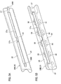
- the sliding contact members 30B are assembled to both front and rear sides of the lower rail 10 respectively, an area free of the sliding contact member 30B could be defined at the central part of the lower rail 10 depending on its dimension, as illustrated in Figs. 6A to 6D . Even in such a case, as they are arranged at a "front-side” sliding contact end and a "rear-side” sliding contact end with which the upper rail 20 and the lower rail 10 are brought into slide contact, it becomes possible to deal with lower rails having a variety of total lengths. For this reason, the commonality of components can be accomplished while suppressing an occurrence of rattling between the lower rail 10 and the upper rail 20.
- a sliding contact member 30B' of a modification illustrated in Figs. 7A and 7B may be adopted in place of the sliding contact member 30B of the second embodiment.
- the sliding contact member 30B' of the modification differs from the above-mentioned sliding contact member 30B in that the restriction pedestal 37b is formed so as to connect with the lower column part 34 and the upper column part 35.
- elements similar to those of the second embodiment are indicated with the same reference numerals and their descriptions are eliminated.
- the effect obtained by the sliding contact member 30B' of the modification is similar to that of the second embodiment.
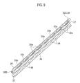
- a seat slide device for vehicle according to a third embodiment will be described with reference to Figs. 8 and 9 .
- the vehicle seat slide device according to the third embodiment greatly differs by the constitution of a sliding contact member 30C as the friction reducing member 30.
- the sliding contact member 30C of the third embodiment differs from the sliding contact member 30B of the second embodiment in that elastic adjustment parts 35a are provided in the upper column part 35 and the other constitution is similar to that of the sliding contact member 30B of the second embodiment.
- the elastic adjustment parts 35a are provided in each region abutting on the upper upside inclined wall 21a between the adjoining friction reducing dents 36.
- Each of the elastic adjustment parts 35a is composed of a recess 35b in the form of an upward-opening cavity along a direction perpendicular to a line connecting the contact point P3 between the lower upside circular part 11f and the upper column part 35 with the contact point P4 between the upper upside inclined wall 21d and the upper column part 35.
- the elastic adjustment parts 35a are elastically deformed in accordance with a clearance between the sliding upper rail 20 and the lower rail 10, it is possible to abolish the process of selectively assembling an appropriate friction reducing member 30 so as to correspond to the clearance between the upper rail 20 and the lower upside circular part 11f and also possible to reduce the types of friction reducing members to be managed.
- the shape of the recess 35b it is not limited to the shape illustrated in the third embodiment, as long as the back side of the region of the upper column part 35 abutting on the upper upside inclined wall 21d is sculpted so as to have appropriate resilience.
- it may be provided with a concave shape which results from removing all the back side of the region of the upper column part 35 abutting on the upper upside inclined wall 21d, and the same effect as this embodiment could be realized.
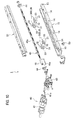
- the seat slide device 1 employs the sliding contact member 30A as the friction reducing member 30, guide balls 30D may be alternatively adopted like the modification illustrated in Figs. 10 and 11 .
- Each of the guide balls 30D includes lower guide balls 31 and upper guide balls 32 both composed of metallic round balls, and a retainer 33 for supporting the lower guide balls 31 between the lower downside circular part 11e and the upper downside inclined wall 21c rollably and also supporting the upper guide balls 32 between the lower upside circular part 11f and the upper upside inclined wall 21c rollably.
- each of the lower guide balls 31 is set to have the same diameter as the lower column part 34 of the first embodiment, while each of the upper guide balls 32 is set to have the same diameter as the upper column part 35 of the first embodiment. In other words, the diameter of the lower guide ball 31 is set larger than the diameter of the upper guide ball 32.
- the retainer 33 supports two each for the lower guide ball 31 and the upper guide ball 32, four balls in total. Then, these guide balls 30D are arranged in an accommodation part 12 surrounded by the lower sidewall 11b, the lower top wall 11c and the lower inner wall 11d, at two sites both in front and in the rear, that is, four sets of the guide balls 30D in total are arranged for one assembly 1a.
Landscapes
- Engineering & Computer Science (AREA)
- Aviation & Aerospace Engineering (AREA)
- Transportation (AREA)
- Mechanical Engineering (AREA)
- Seats For Vehicles (AREA)
Applications Claiming Priority (2)
| Application Number | Priority Date | Filing Date | Title |
|---|---|---|---|
| JP2014163330 | 2014-08-11 | ||
| JP2015120861A JP6456253B2 (ja) | 2014-08-11 | 2015-06-16 | シートスライド装置 |
Publications (2)
| Publication Number | Publication Date |
|---|---|
| EP2985174A1 true EP2985174A1 (de) | 2016-02-17 |
| EP2985174B1 EP2985174B1 (de) | 2019-11-20 |
Family
ID=53969139
Family Applications (1)
| Application Number | Title | Priority Date | Filing Date |
|---|---|---|---|
| EP15180369.9A Active EP2985174B1 (de) | 2014-08-11 | 2015-08-10 | Sitzschiebevorrichtung für ein fahrzeug |
Country Status (4)
| Country | Link |
|---|---|
| US (1) | US10046672B2 (de) |
| EP (1) | EP2985174B1 (de) |
| JP (1) | JP6456253B2 (de) |
| CN (1) | CN105365607B (de) |
Cited By (4)
| Publication number | Priority date | Publication date | Assignee | Title |
|---|---|---|---|---|
| EP3369612A1 (de) * | 2017-03-02 | 2018-09-05 | Adient Engineering and IP GmbH | Fahrzeugsitzschienensystem |
| CN110035922A (zh) * | 2016-12-14 | 2019-07-19 | 布罗泽汽车部件制造科堡有限公司 | 用于纵向调节车辆座椅的调节装置 |
| WO2023002356A1 (de) * | 2021-07-22 | 2023-01-26 | Adient Us Llc | Gleitblock für ein sitzschienenpaar und sitzschienenpaar und fahrzeugsitz |
| DE102023125397A1 (de) * | 2023-09-19 | 2025-03-20 | Faurecia Autositze Gmbh | Fahrzeugsitz für ein Fahrzeug |
Families Citing this family (11)
| Publication number | Priority date | Publication date | Assignee | Title |
|---|---|---|---|---|
| JP2017226356A (ja) * | 2016-06-23 | 2017-12-28 | アイシン精機株式会社 | 車両用シートスライド装置 |
| DE102016218236B4 (de) * | 2016-09-22 | 2022-05-05 | Lear Corporation | Sitzschienen-Anordnung |
| CN107953804B (zh) * | 2016-10-14 | 2021-04-09 | 丰田车体精工株式会社 | 座椅滑动装置 |
| DE102017203177A1 (de) * | 2017-02-27 | 2018-08-30 | Bayerische Motoren Werke Aktiengesellschaft | Fahrzeugsitzkonsole |
| JP6842398B2 (ja) * | 2017-10-17 | 2021-03-17 | マツダ株式会社 | シートスライド機構 |
| JP6982507B2 (ja) * | 2018-01-24 | 2021-12-17 | シロキ工業株式会社 | 車両用スライドレール装置 |
| CN109080508B (zh) * | 2018-08-28 | 2020-04-07 | 延锋安道拓座椅机械部件有限公司 | 一种马达直连丝杆电动滑轨 |
| EP3907104B1 (de) * | 2019-01-03 | 2025-08-20 | TS Tech Co., Ltd. | Elektrisch angetriebene gleitschiene und fahrzeugsitz mit elektrisch angetriebener gleitschiene |
| DE102020108799B3 (de) * | 2020-03-30 | 2021-07-22 | Bayerische Motoren Werke Aktiengesellschaft | Sitzschienenpaar zur Längsverstellung eines Fahrzeugsitzes |
| JP7384890B2 (ja) * | 2021-12-22 | 2023-11-21 | 本田技研工業株式会社 | 車両用シート |
| CN114619929A (zh) * | 2022-03-25 | 2022-06-14 | 延锋国际汽车技术有限公司 | 一种滚轮滑柱复合滑轨承载系统 |
Citations (9)
| Publication number | Priority date | Publication date | Assignee | Title |
|---|---|---|---|---|
| DE10156805A1 (de) * | 2000-11-21 | 2002-10-02 | Aisin Seiki | Sitzgleitvorrichtung für ein Fahrzeug |
| JP2005263049A (ja) * | 2004-03-19 | 2005-09-29 | Imasen Electric Ind Co Ltd | スライドレール装置 |
| JP2006168589A (ja) | 2004-12-17 | 2006-06-29 | Toyo Seat Co Ltd | シートのスライド装置 |
| WO2006075815A1 (en) * | 2005-01-12 | 2006-07-20 | Km & I Co., Ltd | Fixing apparatus for seattrack |
| EP1892145A2 (de) * | 2006-08-25 | 2008-02-27 | Aisin Seiki Kabushiki Kaisha | Sitzverschiebevorrichtung für ein Fahrzeug |
| JP2010105618A (ja) | 2008-10-31 | 2010-05-13 | Fuji Kiko Co Ltd | 電動シートスライド装置 |
| US20120006963A1 (en) * | 2010-05-26 | 2012-01-12 | Imasen Electric Industrial Co., Ltd. | Seat slide device |
| WO2012011315A1 (ja) * | 2010-07-22 | 2012-01-26 | シロキ工業株式会社 | 車両用スライドレール装置 |
| CN203727204U (zh) * | 2013-02-19 | 2014-07-23 | 爱信精机株式会社 | 车辆用座椅滑动装置 |
Family Cites Families (17)
| Publication number | Priority date | Publication date | Assignee | Title |
|---|---|---|---|---|
| US5707035A (en) * | 1994-08-31 | 1998-01-13 | Hoover Universal, Inc. | Vehicle seat adjuster |
| US5575564A (en) * | 1995-05-26 | 1996-11-19 | Itt Automotive, Inc. | Seat track apparatus |
| US6352312B1 (en) * | 2000-03-24 | 2002-03-05 | Excellence Manufacturing, Inc. | Vehicle seat interlock |
| US6886797B2 (en) * | 2001-11-01 | 2005-05-03 | Lear Corporation | Seat track assembly |
| KR100442746B1 (ko) * | 2001-11-08 | 2004-08-02 | 주식회사다스 | 자동차용 시트레일의 로킹시스템 |
| JP4000858B2 (ja) * | 2002-02-06 | 2007-10-31 | アイシン精機株式会社 | シート用パワースライド装置 |
| FR2863959B1 (fr) * | 2003-12-18 | 2006-04-07 | Faurecia Sieges Automobile | Glissiere pour siege de vehicule et siege de vehicule comprenant une telle glissiere |
| JP4797625B2 (ja) * | 2005-12-28 | 2011-10-19 | アイシン精機株式会社 | 車両用シートスライド装置 |
| JP2008074380A (ja) * | 2006-08-25 | 2008-04-03 | Aisin Seiki Co Ltd | 車両用シートスライド装置 |
| US8052111B2 (en) * | 2007-10-22 | 2011-11-08 | Lear Corporation | Seat track assembly |
| US8251336B2 (en) * | 2008-07-09 | 2012-08-28 | Shiroki Corporation | Seat track mechanism for vehicle |
| US8245994B2 (en) * | 2009-01-29 | 2012-08-21 | Aisin Seiki Kabushiki Kaisha | Seat apparatus for vehicle |
| JP4947123B2 (ja) * | 2009-11-04 | 2012-06-06 | アイシン精機株式会社 | 車両用スライド装置 |
| JP5327002B2 (ja) * | 2009-11-05 | 2013-10-30 | アイシン精機株式会社 | 車両用シートスライド装置 |
| JP5760434B2 (ja) * | 2010-12-27 | 2015-08-12 | 株式会社今仙電機製作所 | シートレール装置 |
| US8702053B2 (en) * | 2011-05-26 | 2014-04-22 | Ford Global Technologies, Llc | Vehicle seat interface assembly |
| US10518666B2 (en) * | 2014-10-14 | 2019-12-31 | Saint-Gobain Performance Plastics Pampus Gmbh | Linear motion assemblies and bearings for use in linear motion assemblies |
-
2015
- 2015-06-16 JP JP2015120861A patent/JP6456253B2/ja active Active
- 2015-08-10 EP EP15180369.9A patent/EP2985174B1/de active Active
- 2015-08-10 CN CN201510487034.2A patent/CN105365607B/zh not_active Expired - Fee Related
- 2015-08-10 US US14/821,833 patent/US10046672B2/en not_active Expired - Fee Related
Patent Citations (9)
| Publication number | Priority date | Publication date | Assignee | Title |
|---|---|---|---|---|
| DE10156805A1 (de) * | 2000-11-21 | 2002-10-02 | Aisin Seiki | Sitzgleitvorrichtung für ein Fahrzeug |
| JP2005263049A (ja) * | 2004-03-19 | 2005-09-29 | Imasen Electric Ind Co Ltd | スライドレール装置 |
| JP2006168589A (ja) | 2004-12-17 | 2006-06-29 | Toyo Seat Co Ltd | シートのスライド装置 |
| WO2006075815A1 (en) * | 2005-01-12 | 2006-07-20 | Km & I Co., Ltd | Fixing apparatus for seattrack |
| EP1892145A2 (de) * | 2006-08-25 | 2008-02-27 | Aisin Seiki Kabushiki Kaisha | Sitzverschiebevorrichtung für ein Fahrzeug |
| JP2010105618A (ja) | 2008-10-31 | 2010-05-13 | Fuji Kiko Co Ltd | 電動シートスライド装置 |
| US20120006963A1 (en) * | 2010-05-26 | 2012-01-12 | Imasen Electric Industrial Co., Ltd. | Seat slide device |
| WO2012011315A1 (ja) * | 2010-07-22 | 2012-01-26 | シロキ工業株式会社 | 車両用スライドレール装置 |
| CN203727204U (zh) * | 2013-02-19 | 2014-07-23 | 爱信精机株式会社 | 车辆用座椅滑动装置 |
Cited By (8)
| Publication number | Priority date | Publication date | Assignee | Title |
|---|---|---|---|---|
| CN110035922A (zh) * | 2016-12-14 | 2019-07-19 | 布罗泽汽车部件制造科堡有限公司 | 用于纵向调节车辆座椅的调节装置 |
| CN110035922B (zh) * | 2016-12-14 | 2022-01-14 | 布罗泽汽车部件制造科堡有限公司 | 用于纵向调节车辆座椅的调节装置 |
| US11299071B2 (en) | 2016-12-14 | 2022-04-12 | Brose Fahrzeugteile Gmbh & Co. Kommanditgesellschaft, Coburg | Adjustment device for the longitudinal adjustment of a vehicle seat |
| EP3369612A1 (de) * | 2017-03-02 | 2018-09-05 | Adient Engineering and IP GmbH | Fahrzeugsitzschienensystem |
| US11077772B2 (en) | 2017-03-02 | 2021-08-03 | Keiper Seating Mechanisms Co., Ltd | Vehicle seat track system |
| WO2023002356A1 (de) * | 2021-07-22 | 2023-01-26 | Adient Us Llc | Gleitblock für ein sitzschienenpaar und sitzschienenpaar und fahrzeugsitz |
| US12576754B2 (en) | 2021-07-22 | 2026-03-17 | Adient Us Llc | Sliding block for a pair of seat rails, and vehicle seat |
| DE102023125397A1 (de) * | 2023-09-19 | 2025-03-20 | Faurecia Autositze Gmbh | Fahrzeugsitz für ein Fahrzeug |
Also Published As
| Publication number | Publication date |
|---|---|
| US10046672B2 (en) | 2018-08-14 |
| JP2016040162A (ja) | 2016-03-24 |
| EP2985174B1 (de) | 2019-11-20 |
| CN105365607A (zh) | 2016-03-02 |
| CN105365607B (zh) | 2018-07-20 |
| US20160039313A1 (en) | 2016-02-11 |
| JP6456253B2 (ja) | 2019-01-23 |
Similar Documents
| Publication | Publication Date | Title |
|---|---|---|
| EP2985174B1 (de) | Sitzschiebevorrichtung für ein fahrzeug | |
| US8584325B2 (en) | Structure for fastening clip to trim board, clip, and clip fastening method | |
| US8485489B2 (en) | Longitudinal adjustment mechanism for seats | |
| CN106394205B (zh) | 面板密封设备以及面板密封设备的组装方法 | |
| US11173809B2 (en) | Electric seat slide device | |
| JP2009530152A (ja) | 自動車の座席のための膨らんだスライダ | |
| EP3199328A1 (de) | Dreidimensionaler drucker mit hebevorrichtung für die bauplattform | |
| JP6763822B2 (ja) | スタビライザー | |
| US9387779B2 (en) | Seat track assembly having selectable end stop positions | |
| CN104210529A (zh) | 车辆用倾动或倾动和伸缩转向装置 | |
| EP0697306A1 (de) | Gleitschienenlaufbahn, insbesondere für Fahrzeugsitze | |
| US20140190086A1 (en) | Window regulator | |
| JP5085900B2 (ja) | シートトラック装置 | |
| KR101470183B1 (ko) | 자동차 시트의 슬라이딩 이동 장치 | |
| KR20040032966A (ko) | 슬라이드 장치 | |
| JP2013076289A (ja) | 戸車及び建具 | |
| KR102402992B1 (ko) | 자동차의 시트레일 | |
| WO2020109626A1 (en) | A vehicle seat platform | |
| DE202010008626U1 (de) | Clipselement | |
| CN102267495A (zh) | 对于可旋转的车身配件的制动排布 | |
| GB2487761A (en) | Sliding supports | |
| EP1693246A2 (de) | Fahrzeugsitzschiene | |
| US12145475B2 (en) | Longitudinal adjuster, method for assembling a longitudinal adjuster, and vehicle seat | |
| CN102198859B (zh) | 用于机舱内部组件的装配装置 | |
| JPH0650332A (ja) | 直線案内装置 |
Legal Events
| Date | Code | Title | Description |
|---|---|---|---|
| PUAI | Public reference made under article 153(3) epc to a published international application that has entered the european phase |
Free format text: ORIGINAL CODE: 0009012 |
|
| AK | Designated contracting states |
Kind code of ref document: A1 Designated state(s): AL AT BE BG CH CY CZ DE DK EE ES FI FR GB GR HR HU IE IS IT LI LT LU LV MC MK MT NL NO PL PT RO RS SE SI SK SM TR |
|
| AX | Request for extension of the european patent |
Extension state: BA ME |
|
| 17P | Request for examination filed |
Effective date: 20160810 |
|
| RBV | Designated contracting states (corrected) |
Designated state(s): AL AT BE BG CH CY CZ DE DK EE ES FI FR GB GR HR HU IE IS IT LI LT LU LV MC MK MT NL NO PL PT RO RS SE SI SK SM TR |
|
| RAP1 | Party data changed (applicant data changed or rights of an application transferred) |
Owner name: TF-METAL CO., LTD. |
|
| RIC1 | Information provided on ipc code assigned before grant |
Ipc: B60N 2/07 20060101AFI20181018BHEP Ipc: B60N 2/075 20060101ALI20181018BHEP Ipc: B60N 2/06 20060101ALI20181018BHEP |
|
| STAA | Information on the status of an ep patent application or granted ep patent |
Free format text: STATUS: EXAMINATION IS IN PROGRESS |
|
| 17Q | First examination report despatched |
Effective date: 20181206 |
|
| GRAP | Despatch of communication of intention to grant a patent |
Free format text: ORIGINAL CODE: EPIDOSNIGR1 |
|
| STAA | Information on the status of an ep patent application or granted ep patent |
Free format text: STATUS: GRANT OF PATENT IS INTENDED |
|
| INTG | Intention to grant announced |
Effective date: 20190726 |
|
| RIN1 | Information on inventor provided before grant (corrected) |
Inventor name: KURODA, SHUNSUKE |
|
| GRAS | Grant fee paid |
Free format text: ORIGINAL CODE: EPIDOSNIGR3 |
|
| GRAA | (expected) grant |
Free format text: ORIGINAL CODE: 0009210 |
|
| STAA | Information on the status of an ep patent application or granted ep patent |
Free format text: STATUS: THE PATENT HAS BEEN GRANTED |
|
| AK | Designated contracting states |
Kind code of ref document: B1 Designated state(s): AL AT BE BG CH CY CZ DE DK EE ES FI FR GB GR HR HU IE IS IT LI LT LU LV MC MK MT NL NO PL PT RO RS SE SI SK SM TR |
|
| REG | Reference to a national code |
Ref country code: GB Ref legal event code: FG4D |
|
| REG | Reference to a national code |
Ref country code: CH Ref legal event code: EP |
|
| REG | Reference to a national code |
Ref country code: IE Ref legal event code: FG4D |
|
| REG | Reference to a national code |
Ref country code: DE Ref legal event code: R096 Ref document number: 602015041939 Country of ref document: DE |
|
| REG | Reference to a national code |
Ref country code: AT Ref legal event code: REF Ref document number: 1203814 Country of ref document: AT Kind code of ref document: T Effective date: 20191215 |
|
| REG | Reference to a national code |
Ref country code: NL Ref legal event code: MP Effective date: 20191120 |
|
| REG | Reference to a national code |
Ref country code: LT Ref legal event code: MG4D |
|
| PG25 | Lapsed in a contracting state [announced via postgrant information from national office to epo] |
Ref country code: NL Free format text: LAPSE BECAUSE OF FAILURE TO SUBMIT A TRANSLATION OF THE DESCRIPTION OR TO PAY THE FEE WITHIN THE PRESCRIBED TIME-LIMIT Effective date: 20191120 Ref country code: GR Free format text: LAPSE BECAUSE OF FAILURE TO SUBMIT A TRANSLATION OF THE DESCRIPTION OR TO PAY THE FEE WITHIN THE PRESCRIBED TIME-LIMIT Effective date: 20200221 Ref country code: LV Free format text: LAPSE BECAUSE OF FAILURE TO SUBMIT A TRANSLATION OF THE DESCRIPTION OR TO PAY THE FEE WITHIN THE PRESCRIBED TIME-LIMIT Effective date: 20191120 Ref country code: SE Free format text: LAPSE BECAUSE OF FAILURE TO SUBMIT A TRANSLATION OF THE DESCRIPTION OR TO PAY THE FEE WITHIN THE PRESCRIBED TIME-LIMIT Effective date: 20191120 Ref country code: NO Free format text: LAPSE BECAUSE OF FAILURE TO SUBMIT A TRANSLATION OF THE DESCRIPTION OR TO PAY THE FEE WITHIN THE PRESCRIBED TIME-LIMIT Effective date: 20200220 Ref country code: LT Free format text: LAPSE BECAUSE OF FAILURE TO SUBMIT A TRANSLATION OF THE DESCRIPTION OR TO PAY THE FEE WITHIN THE PRESCRIBED TIME-LIMIT Effective date: 20191120 Ref country code: FI Free format text: LAPSE BECAUSE OF FAILURE TO SUBMIT A TRANSLATION OF THE DESCRIPTION OR TO PAY THE FEE WITHIN THE PRESCRIBED TIME-LIMIT Effective date: 20191120 Ref country code: BG Free format text: LAPSE BECAUSE OF FAILURE TO SUBMIT A TRANSLATION OF THE DESCRIPTION OR TO PAY THE FEE WITHIN THE PRESCRIBED TIME-LIMIT Effective date: 20200220 |
|
| PG25 | Lapsed in a contracting state [announced via postgrant information from national office to epo] |
Ref country code: RS Free format text: LAPSE BECAUSE OF FAILURE TO SUBMIT A TRANSLATION OF THE DESCRIPTION OR TO PAY THE FEE WITHIN THE PRESCRIBED TIME-LIMIT Effective date: 20191120 Ref country code: IS Free format text: LAPSE BECAUSE OF FAILURE TO SUBMIT A TRANSLATION OF THE DESCRIPTION OR TO PAY THE FEE WITHIN THE PRESCRIBED TIME-LIMIT Effective date: 20200320 Ref country code: HR Free format text: LAPSE BECAUSE OF FAILURE TO SUBMIT A TRANSLATION OF THE DESCRIPTION OR TO PAY THE FEE WITHIN THE PRESCRIBED TIME-LIMIT Effective date: 20191120 |
|
| PG25 | Lapsed in a contracting state [announced via postgrant information from national office to epo] |
Ref country code: AL Free format text: LAPSE BECAUSE OF FAILURE TO SUBMIT A TRANSLATION OF THE DESCRIPTION OR TO PAY THE FEE WITHIN THE PRESCRIBED TIME-LIMIT Effective date: 20191120 |
|
| PG25 | Lapsed in a contracting state [announced via postgrant information from national office to epo] |
Ref country code: PT Free format text: LAPSE BECAUSE OF FAILURE TO SUBMIT A TRANSLATION OF THE DESCRIPTION OR TO PAY THE FEE WITHIN THE PRESCRIBED TIME-LIMIT Effective date: 20200412 Ref country code: EE Free format text: LAPSE BECAUSE OF FAILURE TO SUBMIT A TRANSLATION OF THE DESCRIPTION OR TO PAY THE FEE WITHIN THE PRESCRIBED TIME-LIMIT Effective date: 20191120 Ref country code: DK Free format text: LAPSE BECAUSE OF FAILURE TO SUBMIT A TRANSLATION OF THE DESCRIPTION OR TO PAY THE FEE WITHIN THE PRESCRIBED TIME-LIMIT Effective date: 20191120 Ref country code: ES Free format text: LAPSE BECAUSE OF FAILURE TO SUBMIT A TRANSLATION OF THE DESCRIPTION OR TO PAY THE FEE WITHIN THE PRESCRIBED TIME-LIMIT Effective date: 20191120 Ref country code: CZ Free format text: LAPSE BECAUSE OF FAILURE TO SUBMIT A TRANSLATION OF THE DESCRIPTION OR TO PAY THE FEE WITHIN THE PRESCRIBED TIME-LIMIT Effective date: 20191120 Ref country code: RO Free format text: LAPSE BECAUSE OF FAILURE TO SUBMIT A TRANSLATION OF THE DESCRIPTION OR TO PAY THE FEE WITHIN THE PRESCRIBED TIME-LIMIT Effective date: 20191120 |
|
| REG | Reference to a national code |
Ref country code: AT Ref legal event code: MK05 Ref document number: 1203814 Country of ref document: AT Kind code of ref document: T Effective date: 20191120 |
|
| REG | Reference to a national code |
Ref country code: DE Ref legal event code: R097 Ref document number: 602015041939 Country of ref document: DE |
|
| PG25 | Lapsed in a contracting state [announced via postgrant information from national office to epo] |
Ref country code: SK Free format text: LAPSE BECAUSE OF FAILURE TO SUBMIT A TRANSLATION OF THE DESCRIPTION OR TO PAY THE FEE WITHIN THE PRESCRIBED TIME-LIMIT Effective date: 20191120 Ref country code: SM Free format text: LAPSE BECAUSE OF FAILURE TO SUBMIT A TRANSLATION OF THE DESCRIPTION OR TO PAY THE FEE WITHIN THE PRESCRIBED TIME-LIMIT Effective date: 20191120 |
|
| PLBE | No opposition filed within time limit |
Free format text: ORIGINAL CODE: 0009261 |
|
| STAA | Information on the status of an ep patent application or granted ep patent |
Free format text: STATUS: NO OPPOSITION FILED WITHIN TIME LIMIT |
|
| 26N | No opposition filed |
Effective date: 20200821 |
|
| PGFP | Annual fee paid to national office [announced via postgrant information from national office to epo] |
Ref country code: FR Payment date: 20200826 Year of fee payment: 6 |
|
| PG25 | Lapsed in a contracting state [announced via postgrant information from national office to epo] |
Ref country code: PL Free format text: LAPSE BECAUSE OF FAILURE TO SUBMIT A TRANSLATION OF THE DESCRIPTION OR TO PAY THE FEE WITHIN THE PRESCRIBED TIME-LIMIT Effective date: 20191120 Ref country code: SI Free format text: LAPSE BECAUSE OF FAILURE TO SUBMIT A TRANSLATION OF THE DESCRIPTION OR TO PAY THE FEE WITHIN THE PRESCRIBED TIME-LIMIT Effective date: 20191120 Ref country code: AT Free format text: LAPSE BECAUSE OF FAILURE TO SUBMIT A TRANSLATION OF THE DESCRIPTION OR TO PAY THE FEE WITHIN THE PRESCRIBED TIME-LIMIT Effective date: 20191120 |
|
| PG25 | Lapsed in a contracting state [announced via postgrant information from national office to epo] |
Ref country code: IT Free format text: LAPSE BECAUSE OF FAILURE TO SUBMIT A TRANSLATION OF THE DESCRIPTION OR TO PAY THE FEE WITHIN THE PRESCRIBED TIME-LIMIT Effective date: 20191120 |
|
| REG | Reference to a national code |
Ref country code: DE Ref legal event code: R119 Ref document number: 602015041939 Country of ref document: DE |
|
| PG25 | Lapsed in a contracting state [announced via postgrant information from national office to epo] |
Ref country code: MC Free format text: LAPSE BECAUSE OF FAILURE TO SUBMIT A TRANSLATION OF THE DESCRIPTION OR TO PAY THE FEE WITHIN THE PRESCRIBED TIME-LIMIT Effective date: 20191120 |
|
| REG | Reference to a national code |
Ref country code: CH Ref legal event code: PL |
|
| GBPC | Gb: european patent ceased through non-payment of renewal fee |
Effective date: 20200810 |
|
| PG25 | Lapsed in a contracting state [announced via postgrant information from national office to epo] |
Ref country code: LU Free format text: LAPSE BECAUSE OF NON-PAYMENT OF DUE FEES Effective date: 20200810 Ref country code: LI Free format text: LAPSE BECAUSE OF NON-PAYMENT OF DUE FEES Effective date: 20200831 Ref country code: CH Free format text: LAPSE BECAUSE OF NON-PAYMENT OF DUE FEES Effective date: 20200831 |
|
| REG | Reference to a national code |
Ref country code: BE Ref legal event code: MM Effective date: 20200831 |
|
| PG25 | Lapsed in a contracting state [announced via postgrant information from national office to epo] |
Ref country code: DE Free format text: LAPSE BECAUSE OF NON-PAYMENT OF DUE FEES Effective date: 20210302 |
|
| PG25 | Lapsed in a contracting state [announced via postgrant information from national office to epo] |
Ref country code: IE Free format text: LAPSE BECAUSE OF NON-PAYMENT OF DUE FEES Effective date: 20200810 Ref country code: GB Free format text: LAPSE BECAUSE OF NON-PAYMENT OF DUE FEES Effective date: 20200810 Ref country code: BE Free format text: LAPSE BECAUSE OF NON-PAYMENT OF DUE FEES Effective date: 20200831 |
|
| PG25 | Lapsed in a contracting state [announced via postgrant information from national office to epo] |
Ref country code: TR Free format text: LAPSE BECAUSE OF FAILURE TO SUBMIT A TRANSLATION OF THE DESCRIPTION OR TO PAY THE FEE WITHIN THE PRESCRIBED TIME-LIMIT Effective date: 20191120 Ref country code: MT Free format text: LAPSE BECAUSE OF FAILURE TO SUBMIT A TRANSLATION OF THE DESCRIPTION OR TO PAY THE FEE WITHIN THE PRESCRIBED TIME-LIMIT Effective date: 20191120 Ref country code: CY Free format text: LAPSE BECAUSE OF FAILURE TO SUBMIT A TRANSLATION OF THE DESCRIPTION OR TO PAY THE FEE WITHIN THE PRESCRIBED TIME-LIMIT Effective date: 20191120 |
|
| PG25 | Lapsed in a contracting state [announced via postgrant information from national office to epo] |
Ref country code: MK Free format text: LAPSE BECAUSE OF FAILURE TO SUBMIT A TRANSLATION OF THE DESCRIPTION OR TO PAY THE FEE WITHIN THE PRESCRIBED TIME-LIMIT Effective date: 20191120 |
|
| PG25 | Lapsed in a contracting state [announced via postgrant information from national office to epo] |
Ref country code: FR Free format text: LAPSE BECAUSE OF NON-PAYMENT OF DUE FEES Effective date: 20210831 |