EP2985244A1 - Convoyeur oscillant et procédé d'exploitation d'un convoyeur oscillant - Google Patents
Convoyeur oscillant et procédé d'exploitation d'un convoyeur oscillant Download PDFInfo
- Publication number
- EP2985244A1 EP2985244A1 EP15175691.3A EP15175691A EP2985244A1 EP 2985244 A1 EP2985244 A1 EP 2985244A1 EP 15175691 A EP15175691 A EP 15175691A EP 2985244 A1 EP2985244 A1 EP 2985244A1
- Authority
- EP
- European Patent Office
- Prior art keywords
- coil
- oscillator
- circuit
- signal
- frequency
- Prior art date
- Legal status (The legal status is an assumption and is not a legal conclusion. Google has not performed a legal analysis and makes no representation as to the accuracy of the status listed.)
- Granted
Links
Images

Classifications
-
- B—PERFORMING OPERATIONS; TRANSPORTING
- B65—CONVEYING; PACKING; STORING; HANDLING THIN OR FILAMENTARY MATERIAL
- B65G—TRANSPORT OR STORAGE DEVICES, e.g. CONVEYORS FOR LOADING OR TIPPING, SHOP CONVEYOR SYSTEMS OR PNEUMATIC TUBE CONVEYORS
- B65G27/00—Jigging conveyors
- B65G27/10—Applications of devices for generating or transmitting jigging movements
- B65G27/32—Applications of devices for generating or transmitting jigging movements with means for controlling direction, frequency or amplitude of vibration or shaking movement
-
- G—PHYSICS
- G05—CONTROLLING; REGULATING
- G05D—SYSTEMS FOR CONTROLLING OR REGULATING NON-ELECTRIC VARIABLES
- G05D19/00—Control of mechanical oscillations, e.g. of amplitude, of frequency, of phase
- G05D19/02—Control of mechanical oscillations, e.g. of amplitude, of frequency, of phase characterised by the use of electric means
Definitions
- the invention relates to a vibratory conveyor, comprising a vibrating rail, at least one electromagnet with a coil and an armature coupled to the oscillating rail, which is movable by driving the coil for generating a vibration of the oscillating rail, wherein the coil is part of an oscillator circuit, wherein an oscillator frequency an oscillator signal of the oscillator circuit depends on an inductance of the coil influenced by a position of the armature with respect to the coil.
- Vibratory conveyors are used to transport material along rails, for example, for feeding small components or component components in automated manufacturing processes.
- An elliptical vibrating motion guides the material to be conveyed along a predefined path.
- the elliptical vibrating motion is generated by means of at least one electromagnet.
- the electromagnet periodically attracts an armature connected to the oscillating rail of the oscillating conveyor, wherein a restoring force predetermined by an elasticity, typically by leaf springs, acts on the oscillating rail and thus on the armature.
- the magnitude of the oscillation amplitude is related to the delivery rate, which is why the largest possible oscillation amplitude should be achieved.
- the vibratory conveyor should be operated close to its resonance frequency.
- the problem here is that the oscillation of the vibratory conveyor is typically not linear due to its structure, which even small deviations from the resonant frequency can lead to strong changes in the oscillation amplitude or to a collapse of the oscillation.
- the invention has for its object to provide a vibrating conveyor, which can be reliably driven with little circuit complexity near and / or with the resonant frequency of the vibrating conveyor.
- the object is achieved by a vibrating conveyor of the type mentioned, wherein the vibrating conveyor comprises a feedback circuit, which drives the coil with a time course of a frequency change of the oscillator frequency imaging control signal.
- the vibratory conveyor is driven by supplying a predetermined vibration or by predetermined current pulses to the coil to use a self-excitation.
- the control of the coil of the vibratory conveyor is effected by a signal which is derived from the vibration of the vibratory conveyor itself.
- the inductance of the coil depends on the position of the armature with respect to the coil.
- a coil of a vibrating conveyor may in particular be applied to a yoke, which bundles the magnetic field lines of the coil. Depending on the size of the air gap between the yoke and the armature, the inductance of the coil changes.
- an oscillator circuit which comprises the coil, in particular as an element of a resonant circuit of the oscillator circuit
- the oscillator frequency of the oscillator signal of the oscillator depends on the distance between armature and coil. If the distance between the armature and the coil is low, then the coil has a large inductance, which, when used in a resonant circuit leads to a low resonant frequency of the resonant circuit and thus to a low oscillator frequency. With increasing distance between the armature and the coil, the oscillator circuit is detuned to higher frequencies.
- the relationship between the oscillator frequency and a distance between the armature and the coil is thus strictly monotone, whereby a frequency change of the oscillator frequency can be approximated as a position signal of the armature.
- the course of a frequency change of the oscillator frequency thus corresponds to a "distorted" course of the distance between armature and coil.
- the feedback circuit may comprise a demodulation circuit for frequency demodulation, which is designed to generate from the oscillator signal, the control signal or a measurement signal in response to which the control signal is provided.
- the oscillator signal has due to the vibration of the vibratory conveyor and thus due to the movement of the armature relative to the coil to a time-varying oscillator frequency.
- the oscillator signal can thus be interpreted as a signal having a carrier frequency which is frequency modulated by a modulation signal.
- the demodulation circuit may in particular comprise a phase-locked loop.
- the phase locked loop may include a voltage controlled oscillator and a phase detector, wherein the phase detector detects a relative phase angle between the voltage controlled internal oscillator and the supplied oscillator signal.
- a phase detector may be designed such that the supplied oscillator signal and the signal of the internal oscillator, for example by saturation, are converted into signals with exactly two possible values and the two signals are combined with an XOR gate. Numerous other phase detectors are known in the prior art.
- the output signal of the phase detector can be fed to a loop filter with a predetermined cutoff frequency.
- the output signal of the loop filter can be fed back as a control voltage to the voltage-controlled oscillator. If a voltage-controlled oscillator with a linear frequency control is used, then the output signal of the loop filter, that is the control voltage of the oscillator, apart from a constant offset, essentially corresponds to the time profile of a frequency change of the input signal.
- a phase-locked loop which is supplied as an input signal, the oscillator signal, a signal is thus provided as an output signal, which maps a time course of a frequency change of the oscillator frequency.
- An existing offset of the output signal can be removed for example by a DC filter and / or the feedback circuit can be adjusted so that the offset is zero.
- phase-locked loop in the demodulation circuit
- other circuits for frequency demodulation can be used, for example discriminator circuits, in particular edge, difference or phase discriminators.
- the feedback circuit may comprise a phase shift circuit, which is designed to provide the control signal, the phase angle of the To change the measuring signal.
- a phase shift circuit which is designed to provide the control signal, the phase angle of the To change the measuring signal.
- the time profile of the frequency change of the oscillator frequency approximates a change in the position of the armature.
- the time profile of the excitation force is shifted 90 ° relative to a locus of the oscillation.
- a phase shift by 90 ° for example, by a capacitor, in particular with a downstream operational amplifier, ie with a Differenziatorscnies, can be achieved.
- the phase angle of the control signal can be adjusted by, for example, an ohmic resistance being provided in parallel with the capacitor.
- an adjustable ohmic resistance may be provided to allow subsequent adjustment of the phase position.
- other phase shifter circuits for example an all-pass filter, can also be used.
- the feedback circuit comprises an amplifier circuit which is designed to amplify the measurement signal in order to provide the control signal.
- the coil of the electromagnet of the vibratory conveyor can be operated with relatively high voltages, for example 110 or 220 volts, and large currents can flow.
- Signal processing, in particular demodulation of the oscillator signal, by power electronics is relatively complicated and expensive. Therefore, it is advantageous to perform the above-described processing of the oscillator signal at relatively low voltages and currents, for example in a voltage range ⁇ 10 volts.
- the control signal can be amplified before it is fed to the coil. An amplification is possible for example by Mosfets, IGBTs or the like.
- the measurement signal is first phase-shifted and then amplified to provide the control signal. Before or after the phase shift of the measurement signal this can be additionally filtered, for example, higher harmonic vibration components, the measurement signal, in particular due to the non-linear relationship between the location of the armature and the frequency change of the oscillator frequency, comprises removing from the measurement signal.
- the vibratory conveyor comprises a starter circuit, which is designed to control the coil for a predetermined time interval with a predetermined drive signal.
- the starter circuit may be configured to supply a voltage or current pulse to the coil. It is possible that the starting circuit is formed completely separate from the feedback circuit, but advantageously the drive signal of the starter circuit is passed through the amplifier circuit described above.
- the control signal serves, in particular, to deflect the vibratory conveyor once, so that the vibratory conveyor then initially oscillates freely with its resonant frequency. This free vibration also leads to a change in frequency of the oscillator frequency, which, as described above, a control signal is ready to operate the vibratory conveyor self-excited. Alternatively, it would also be possible to start the vibratory conveyor by a mechanical excitation.
- the oscillator circuit may in particular comprise capacitors connected in series with one another and parallel to the coil, wherein a tap for the oscillator signal is provided between the capacitors.
- a tap for the oscillator signal is provided between the capacitors.
- the oscillator circuit it is possible for the oscillator circuit to comprise two further capacitors connected in series with one another and parallel to the coil, wherein a feedback point for the oscillator signal is provided between the further capacitors.
- the oscillator frequency can be at least five times, in particular at least ten times, as large as a resonant frequency of the oscillation of the oscillating rail. This ensures that the frequency of the course of the frequency change of the oscillator frequency is significantly lower than the oscillator frequency itself, whereby a demodulation can be facilitated.
- the cutoff frequency is significantly, for example, by a factor of five, below the oscillator frequency, whereby a smoother output signal can be provided.
- the oscillating rail is mounted in the vibratory conveyor according to the invention by at least one leaf spring with a plurality of spring layers, wherein the spring layers are each spaced by a spacer element and / or wherein a friction-reducing element between the spring layers is arranged.
- friction between the spring layers of the leaf springs supporting the vibrating rail is typically used to dampen vibration of the vibrating rail and thus reduce the quality factor of the vibration. This is necessary because the vibration of a vibratory conveyor is typically non-linear and a stable vibration near the resonant frequency is hardly possible with extraneous, nonlinear vibration.
- the invention in addition to the vibratory conveyor, relates to a method for operating a vibrating conveyor comprising a vibrating rail, at least one electromagnet with a coil and an armature coupled to the oscillating rail, wherein the armature is moved by a drive of the coil, whereby a vibration of the oscillating rail is formed, wherein the coil is part of an oscillator circuit, wherein an oscillator frequency of an oscillator signal of the oscillator circuit depends on an inductance of the coil influenced by a position of the armature with respect to the coil, wherein the vibratory conveyor comprises a feedback circuit, wherein the coil is driven by the feedback circuit with a control signal representing a time variation of a frequency change of an oscillator frequency.
- the feedback circuit may comprise a demodulation circuit for frequency demodulation, by which the control signal or a measurement signal, in response to which the control signal is provided, is generated from the oscillator signal.
- the feedback circuit comprises a phase shifter circuit, by means of which the phase position of the measurement signal for providing the control signal is changed.
- the feedback circuit may include an amplifier circuit by which the measurement signal is amplified to provide the control signal.
- the vibratory conveyor may comprise a start circuit, by which the coil is driven for a predetermined time interval with a predetermined drive signal.
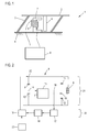
- FIG. 1 shows a vibrating conveyor 1, which comprises a vibrating rail 2, on which goods can be transported by vibrations of the oscillating rail 2.
- the oscillating rail 2 is mounted on a bottom plate 4 via leaf springs 3.
- the oscillating conveyor 1 comprises the coil 5, which can be supplied with current by an electronic control unit 6. If the coil 5 is energized, then a magnetic field is generated, which is bundled by the yoke 7, whereby the coupled with the oscillating rail 2 armature 8 in the direction of the yoke 7, that is pulled in the direction of the coil 5.
- the coil 5 If the coil 5 is energized by the control electronics 6 with a periodic signal, the attraction of the coil 5 varies periodically on the armature 8, whereby the armature 8 and thus the oscillating rail 2 is vibrated. In order to achieve large oscillation amplitudes of the oscillating rail 2 and thus a high delivery rate with a low energy input, the energization of the coil 5 should be carried out with a periodicity corresponding to a mechanical resonance frequency of the vibratory conveyor 1.
- a stable excitation at or near the mechanical resonance frequency of the vibratory conveyor 1 is achieved in the vibratory conveyor 1 by a self-excitation of the vibratory conveyor 1 is provided, in which the coil 5 is energized by the control electronics 6 with a signal which depends on the vibration of the oscillating rail. 2 the vibratory conveyor 1 is generated.
- the armature 8 also vibrates when there is oscillation of the oscillating rail 2 and thus the distance between the yoke 7 and the armature 8 changes. Due to the changing air gap between yoke 7 and Anchor 8 changes at an oscillation of the oscillating rail 2 and the inductance of the coil 5.
- the control electronics 6 is designed to evaluate the inductance change of the coil 5 and to provide a control signal for energizing the coil in response to these inductance changes. This will be described below with reference to FIG. 2 explained in more detail.
- FIG. 2 schematically shows the structure of the control electronics 6 and the connection of the control electronics 6 to the coil 5.
- the coil 5 forms together with the capacitors 9, 10, 11, 12 a resonant circuit.
- a resonant frequency of the resonant circuit is dependent on the inductance of the coil 5, which varies as a function of the oscillation of the oscillating rail 2.
- the resonant circuit forms an oscillator circuit 21 together with a driver circuit 13, wherein the resonant frequency of the resonant circuit determines the oscillator frequency of an oscillator signal of the oscillator circuit 21.
- the oscillator signal of the oscillator circuit 21 is tapped at a tap 14 between the capacitors 9 and 10.
- the capacitors 9 and 10 act as a voltage divider, which at the tap 14 lower maximum voltages are achieved, as applied to the coil 5 during operation of the vibratory conveyor 1.
- the coil 5 are relatively high voltages, for example, up to 220 volts supplied.
- the capacitors 9, 10 are chosen so that the maximum voltage at the tap 14 does not exceed a predetermined value, for example 12 volts.
- the feedback of the oscillator signal and the later explained in more detail evaluation of the oscillator frequency can be done by circuits that are designed for a low-voltage operation.
- the driver circuit 13 In order to maintain an oscillation in the resonant circuit, the driver circuit 13 amplifies the signal tapped at the tapping 14, adjusts the phase of the signal and reinserts it into the resonant circuit at the point 15 between the capacitors 11 and 12.
- the capacitors 11, 12 serve as voltage dividers in accordance with the capacitors 9, 10.
- the resonant frequency of a resonant circuit and thus the oscillator frequency of the oscillator signal of the oscillator circuit 21 is inversely proportional to the root of the inductance of the coil of the resonant circuit.
- the inductance of the coil 5 is increased and the oscillator frequency decreases accordingly and vice versa.
- the oscillator frequency thus varies with a frequency corresponding to the frequency of the oscillation of the oscillating rail.
- the change in the oscillator frequency also has a defined phase position relative to the oscillation of the oscillating rail 2.
- the time profile of the frequency change of the oscillator frequency is thus a suitable measurement signal which can be used as a control signal for the coil 5 or from which a control signal for the coil 5 can be derived to operate the vibratory conveyor at or close to the resonant frequency of the vibratory conveyor 1 ,
- the oscillator signal of the oscillator circuit 21 is coupled out at the connection point 16 and fed to a demodulation circuit 17.
- the demodulation circuit 17 is used for frequency demodulation of the oscillator signal to provide a time course of a frequency change of the oscillator frequency.
- the demodulation of the oscillator signal is carried out by using a phase-locked loop.
- the oscillator signal is fed to an input of a phase detector whose other input is connected to the output of an internal, voltage-controlled oscillator of the phase-locked loop.
- the output signal of the phase detector corresponds to a phase difference between the signal of the internal oscillator and the oscillator circuit.
- phase detector circuits Numerous phase detector circuits are known, which is why, purely by way of example, a saturation of both signals and the feeding of the saturated signals to a digital XOR gate may be mentioned.
- the output signal of the phase detector is fed to a loop filter and the thus filtered signal is used to control the voltage of the internal oscillator.
- At a "locking" of the phase-locked loop corresponds to the Output voltage of the loop filter, apart from a possible offset, the frequency of an incoming signal and thus the oscillator frequency of the oscillator circuit 21.
- a signal is provided which shows a time course of a frequency change of the oscillator frequency of the oscillator circuit 21 pictures.
- This signal is supplied as a measurement signal to a phase shifter circuit 18, which can change the phase of the measurement signal.
- a phase shift is possible, for example, by supplying the measurement signal to a parallel connection between a resistor and a capacitor. Depending on the relative sizes of the resistor and the capacitor, a phase of the resulting current is determined. The current can then be converted back into a voltage, for example by an operational amplifier.
- the inductance of the coil 5 and thus the oscillator frequency of the oscillator circuit 21 varies as explained depending on a distance of the armature 8 to the yoke 7 and the coil 5. The oscillator frequency thus forms, with a certain distortion, a location of the armature 8 and thus the oscillating rail 2 off.
- the excitation signal to be selected would be a signal which is phase-shifted relative to a location of the oscillation of the oscillating rail 2 by 90 °. Even with a non-harmonic oscillation of the vibratory conveyor 1, as is to be expected for the vibratory conveyor 1, a phase shift by the phase shifter circuit 18 of about 90 ° is advantageous.
- the measurement signal Before or after the phase shift, the measurement signal can be filtered in addition by a filter circuit, not shown, to attenuate higher harmonic oscillations of the measurement signal.
- a filter circuit not shown, to attenuate higher harmonic oscillations of the measurement signal.
- the measurement signal may comprise significant harmonic components whose feedback is not desired.
- the measurement signal is then supplied to the amplifier circuit 19, which amplifies the measurement signal and provides a control signal.
- the amplifier circuit 19 is a change in a higher voltage range, with which the coil 5 is operated, for example, a voltage range of up to 220 volts.
- the amplified control signal is coupled into the resonant circuit at the point 22 and thus abuts against the coil 5.
- the demodulation circuit 17, the phase shifter circuit 18 and the amplifier circuit 19 thus together form a feedback circuit 23, which drives the coil with a control signal representing a time variation of a frequency change of the oscillator frequency.
- a self-excitation of the vibrating conveyor 1 is achieved, so that once excited vibration of the vibrating conveyor 1 is stably maintained at or near the resonance frequency.
- the amplitude of the oscillation can be determined by the amplification factor of the amplifier circuit 19.
- the amplitude and additionally the oscillation frequency with respect to the resonant frequency of the vibratory conveyor 1 can be adjusted by adjusting the intensity of the phase change in the phase shifter circuit 18.
- the control electronics 6 comprises a starter circuit 20, which drives the coil for a predetermined time interval with a predetermined drive signal.
- the amplifier circuit 19 is used by the starter circuit 20.
- the drive signal is a current pulse with a defined length.
- a significant advantage of self-excited oscillations is that a stable operation of the vibratory conveyor near or at the resonant frequency is possible, even if no additional damping of the vibratory conveyor 1 is provided.
- leaf springs are used for additional damping of the vibrating conveyor, the spring layers rub against each other and thus withdraw energy from the vibration. Such additional damping is not required in the vibrating conveyor 1 according to the invention.
- the efficiency of the vibratory conveyor 1 according to the invention can thus be further increased by avoiding such additional damping. Therefore, in the vibratory conveyor according to FIG. 1 Used leaf springs 3, as in FIG. 3 are shown shown.
- the leaf springs 3 comprise a plurality of spring layers 24, which are connected via an edge-side connecting element 25.
- Spacers 26 are arranged between the spring layers, due to which cavities 27 are formed between the spring layers 24. Since the spring layers 24 are spaced apart from one another by the cavities 27, they do not rub against one another or, in the case of strong bends, rub against one another much less than in the case of conventional leaf springs, in which the spring layers lie directly against one another. The vibration of the vibratory conveyor 1 is thus less damped than in conventional vibratory conveyors.
- FIG. 4 shows a method for operating a vibrating conveyor 1, wherein the vibrating conveyor 1 is operated even excited.
- the construction of the vibrating conveyor 1 is the same as with reference to FIG FIG. 1 to FIG. 3 illustrated vibratory conveyor 1.
- step S1 a vibration of the oscillator circuit 21, which includes the coil 5, tapped at a tap 14.
- the oscillator oscillation is fed back to the resonant circuit formed by the coil 5 and the capacitors 9, 10, 11, 12 and, on the other hand, fed to a demodulation circuit 17.
- step S2 the oscillator oscillation is demodulated by the demodulation circuit 17, thus providing a signal whose course one Frequency change of the oscillator frequency corresponds. This signal is shifted in phase by the phase shift circuit 18 in step S3.
- the phase-shifted signal is amplified in step S4 and to provide a control signal, which is used in step S5 to drive the coil.
Landscapes
- Engineering & Computer Science (AREA)
- Mechanical Engineering (AREA)
- Physics & Mathematics (AREA)
- General Physics & Mathematics (AREA)
- Automation & Control Theory (AREA)
- Jigging Conveyors (AREA)
- General Induction Heating (AREA)
Applications Claiming Priority (1)
| Application Number | Priority Date | Filing Date | Title |
|---|---|---|---|
| DE102014111166.4A DE102014111166B4 (de) | 2014-08-06 | 2014-08-06 | Schwingförderer und Verfahren zum Betrieb eines Schwingförderers |
Publications (2)
| Publication Number | Publication Date |
|---|---|
| EP2985244A1 true EP2985244A1 (fr) | 2016-02-17 |
| EP2985244B1 EP2985244B1 (fr) | 2019-04-10 |
Family
ID=53540657
Family Applications (1)
| Application Number | Title | Priority Date | Filing Date |
|---|---|---|---|
| EP15175691.3A Active EP2985244B1 (fr) | 2014-08-06 | 2015-07-07 | Convoyeur oscillant et procédé d'exploitation d'un convoyeur oscillant |
Country Status (5)
| Country | Link |
|---|---|
| US (1) | US9884728B2 (fr) |
| EP (1) | EP2985244B1 (fr) |
| CA (1) | CA2897703C (fr) |
| DE (1) | DE102014111166B4 (fr) |
| DK (1) | DK2985244T3 (fr) |
Families Citing this family (4)
| Publication number | Priority date | Publication date | Assignee | Title |
|---|---|---|---|---|
| US20170029261A1 (en) * | 2015-07-31 | 2017-02-02 | Spraying Systems Co. | System for filling liquid containing bottles |
| US10046916B1 (en) * | 2017-02-14 | 2018-08-14 | General Kinematics Corporation | Vibratory apparatus with structural resilient member |
| US10718992B2 (en) * | 2018-04-24 | 2020-07-21 | Samsung Electro-Mechanics Co., Ltd. | Camera module and portable electronic device |
| DE102019119911A1 (de) * | 2019-07-23 | 2021-01-28 | Herrmann Ultraschalltechnik Gmbh & Co. Kg | Verfahren und Generator zur Charakterisierung eines Schwingsystems |
Citations (2)
| Publication number | Priority date | Publication date | Assignee | Title |
|---|---|---|---|---|
| DE19531674A1 (de) | 1995-08-29 | 1997-03-06 | Mrw Digit Electronicgeraete Gm | Steuergerät für elektrisch angetriebene Vibrationsförderer |
| DE69407219T2 (de) * | 1993-06-16 | 1998-07-09 | Ykk Corp | Verfahren und Vorrichtung zum Steuern des Antriebs von selbst-erregten Vibrationsförderern |
Family Cites Families (5)
| Publication number | Priority date | Publication date | Assignee | Title |
|---|---|---|---|---|
| US4194238A (en) * | 1977-03-04 | 1980-03-18 | Sanyo Electric Company, Ltd. | Power supply apparatus |
| JPH10513586A (ja) * | 1995-01-27 | 1998-12-22 | ポール・ヨハンセン・ディベロップメント・エイ/エス | 振動コンベヤ |
| DE29623652U1 (de) * | 1995-01-27 | 1999-07-29 | Poul Johansen Development A/S, Arup | Schwingförderer |
| US5777232A (en) * | 1995-03-29 | 1998-07-07 | Shinko Electric Co., Ltd. | Control system for vibratory apparatus |
| US6192754B1 (en) * | 1995-09-19 | 2001-02-27 | Czarnek And Orkin Laboratories, Inc. | Sensor system for measuring displacements |
-
2014
- 2014-08-06 DE DE102014111166.4A patent/DE102014111166B4/de active Active
-
2015
- 2015-07-07 EP EP15175691.3A patent/EP2985244B1/fr active Active
- 2015-07-07 DK DK15175691.3T patent/DK2985244T3/da active
- 2015-07-17 CA CA2897703A patent/CA2897703C/fr active Active
- 2015-08-04 US US14/817,309 patent/US9884728B2/en active Active
Patent Citations (2)
| Publication number | Priority date | Publication date | Assignee | Title |
|---|---|---|---|---|
| DE69407219T2 (de) * | 1993-06-16 | 1998-07-09 | Ykk Corp | Verfahren und Vorrichtung zum Steuern des Antriebs von selbst-erregten Vibrationsförderern |
| DE19531674A1 (de) | 1995-08-29 | 1997-03-06 | Mrw Digit Electronicgeraete Gm | Steuergerät für elektrisch angetriebene Vibrationsförderer |
Also Published As
| Publication number | Publication date |
|---|---|
| DK2985244T3 (da) | 2019-06-24 |
| US20160039613A1 (en) | 2016-02-11 |
| EP2985244B1 (fr) | 2019-04-10 |
| CA2897703A1 (fr) | 2016-02-06 |
| US9884728B2 (en) | 2018-02-06 |
| DE102014111166A1 (de) | 2016-02-25 |
| CA2897703C (fr) | 2019-11-12 |
| DE102014111166B4 (de) | 2017-10-19 |
Similar Documents
| Publication | Publication Date | Title |
|---|---|---|
| EP2985244B1 (fr) | Convoyeur oscillant et procédé d'exploitation d'un convoyeur oscillant | |
| DE68925902T2 (de) | Stromquelle für eine wechselnde last mit einer induktiven last | |
| DE2158347A1 (de) | Torsionsschwinger | |
| DE102017210356A1 (de) | Eine vorrichtung und ein verfahren zum steuern eines haptischen aktuators | |
| DE1488534C3 (de) | Schaltung zur Erzeugung von in der Phasenlage verschiebbaren Impulsen zur Stromsteuerung von Antriebsmagneten für Vibrationsgeräte | |
| DE1928454A1 (de) | Resonanzspektrometer mit Impulsmodulation | |
| DE3433499C2 (de) | Pendeldrucker | |
| DE2139682C3 (de) | Drahtlos mit einem periodischen Steuersignal synchronisierte elektrische Uhr | |
| DE10023306C2 (de) | Verfahren zur Ansteuerung von piezoelektrischen Antrieben in Füllstandmessgeräten | |
| DE2847208C2 (de) | Ansteuerschaltung für ein schwingungsfähiges elektromechanisches System | |
| DE2943510C2 (de) | Phasengeregelter Hochfrequenzoszillator | |
| DE3644811C2 (fr) | ||
| EP2979311A1 (fr) | Agencement de circuit et procédé d'excitation d'un transformateur piézoélectrique | |
| EP2390634B1 (fr) | Dispositif de fonctionnement d'une unité pivotante d'un résonateur à vibrations | |
| DE2228008B2 (de) | Verfahren und Vorrichtung zur Erzeugung eines Sendesignals mit einer in einem starren Verhältnis zur Netzfrequenz des Stromversorgungsnetzes stehenden Sendefrequenz und Anwendung dieses Verfahrens | |
| DE102020132640B3 (de) | Effizienter Antrieb für piezoelektrische Trägheitsmotoren | |
| DE102006042695B4 (de) | Selbsterregender PWM-Controller für einen Einphasenultraschallmotor | |
| CH676166A5 (fr) | ||
| DE965565C (de) | Verfahren und Vorrichtung zum Umwandeln der mechanischen Schwingungen eines Uhrwerkes in eine elektrische Spannung | |
| DE2143075C3 (de) | Trägerfrequenzsystem | |
| DE102006054597B4 (de) | Steuervorrichtung eines Ultraschallmotors | |
| DE102008042519A1 (de) | Verfahren zur Regelung einer Grundfrequenz eines spannungsgesteuerten Oszillators als eine Trägerfrequenz eines frequenzmodulierten Signals | |
| DE102017222089B4 (de) | Vorrichtung und Verfahren zum Steuern einer oszillierenden Vorrichtung | |
| DE484462C (de) | Verfahren zur Beeinflussung der Helligkeit eines Lichtstrahles mittels mechanisch schwingender Koerper | |
| DD262084A1 (de) | Schaltungsanordnung zur elektronischen anregung eines feder-masse-schwingers in seiner resonanzfrequenz |
Legal Events
| Date | Code | Title | Description |
|---|---|---|---|
| PUAI | Public reference made under article 153(3) epc to a published international application that has entered the european phase |
Free format text: ORIGINAL CODE: 0009012 |
|
| AK | Designated contracting states |
Kind code of ref document: A1 Designated state(s): AL AT BE BG CH CY CZ DE DK EE ES FI FR GB GR HR HU IE IS IT LI LT LU LV MC MK MT NL NO PL PT RO RS SE SI SK SM TR |
|
| AX | Request for extension of the european patent |
Extension state: BA ME |
|
| 17P | Request for examination filed |
Effective date: 20160816 |
|
| RBV | Designated contracting states (corrected) |
Designated state(s): AL AT BE BG CH CY CZ DE DK EE ES FI FR GB GR HR HU IE IS IT LI LT LU LV MC MK MT NL NO PL PT RO RS SE SI SK SM TR |
|
| STAA | Information on the status of an ep patent application or granted ep patent |
Free format text: STATUS: EXAMINATION IS IN PROGRESS |
|
| 17Q | First examination report despatched |
Effective date: 20180614 |
|
| GRAP | Despatch of communication of intention to grant a patent |
Free format text: ORIGINAL CODE: EPIDOSNIGR1 |
|
| STAA | Information on the status of an ep patent application or granted ep patent |
Free format text: STATUS: GRANT OF PATENT IS INTENDED |
|
| INTG | Intention to grant announced |
Effective date: 20181220 |
|
| GRAS | Grant fee paid |
Free format text: ORIGINAL CODE: EPIDOSNIGR3 |
|
| GRAA | (expected) grant |
Free format text: ORIGINAL CODE: 0009210 |
|
| STAA | Information on the status of an ep patent application or granted ep patent |
Free format text: STATUS: THE PATENT HAS BEEN GRANTED |
|
| AK | Designated contracting states |
Kind code of ref document: B1 Designated state(s): AL AT BE BG CH CY CZ DE DK EE ES FI FR GB GR HR HU IE IS IT LI LT LU LV MC MK MT NL NO PL PT RO RS SE SI SK SM TR |
|
| REG | Reference to a national code |
Ref country code: GB Ref legal event code: FG4D Free format text: NOT ENGLISH |
|
| REG | Reference to a national code |
Ref country code: CH Ref legal event code: EP Ref country code: AT Ref legal event code: REF Ref document number: 1118360 Country of ref document: AT Kind code of ref document: T Effective date: 20190415 |
|
| REG | Reference to a national code |
Ref country code: IE Ref legal event code: FG4D Free format text: LANGUAGE OF EP DOCUMENT: GERMAN |
|
| REG | Reference to a national code |
Ref country code: DE Ref legal event code: R096 Ref document number: 502015008608 Country of ref document: DE |
|
| REG | Reference to a national code |
Ref country code: DK Ref legal event code: T3 Effective date: 20190621 |
|
| REG | Reference to a national code |
Ref country code: NL Ref legal event code: MP Effective date: 20190410 |
|
| REG | Reference to a national code |
Ref country code: LT Ref legal event code: MG4D |
|
| PG25 | Lapsed in a contracting state [announced via postgrant information from national office to epo] |
Ref country code: NL Free format text: LAPSE BECAUSE OF FAILURE TO SUBMIT A TRANSLATION OF THE DESCRIPTION OR TO PAY THE FEE WITHIN THE PRESCRIBED TIME-LIMIT Effective date: 20190410 |
|
| PG25 | Lapsed in a contracting state [announced via postgrant information from national office to epo] |
Ref country code: SE Free format text: LAPSE BECAUSE OF FAILURE TO SUBMIT A TRANSLATION OF THE DESCRIPTION OR TO PAY THE FEE WITHIN THE PRESCRIBED TIME-LIMIT Effective date: 20190410 Ref country code: HR Free format text: LAPSE BECAUSE OF FAILURE TO SUBMIT A TRANSLATION OF THE DESCRIPTION OR TO PAY THE FEE WITHIN THE PRESCRIBED TIME-LIMIT Effective date: 20190410 Ref country code: NO Free format text: LAPSE BECAUSE OF FAILURE TO SUBMIT A TRANSLATION OF THE DESCRIPTION OR TO PAY THE FEE WITHIN THE PRESCRIBED TIME-LIMIT Effective date: 20190710 Ref country code: FI Free format text: LAPSE BECAUSE OF FAILURE TO SUBMIT A TRANSLATION OF THE DESCRIPTION OR TO PAY THE FEE WITHIN THE PRESCRIBED TIME-LIMIT Effective date: 20190410 Ref country code: PT Free format text: LAPSE BECAUSE OF FAILURE TO SUBMIT A TRANSLATION OF THE DESCRIPTION OR TO PAY THE FEE WITHIN THE PRESCRIBED TIME-LIMIT Effective date: 20190910 Ref country code: AL Free format text: LAPSE BECAUSE OF FAILURE TO SUBMIT A TRANSLATION OF THE DESCRIPTION OR TO PAY THE FEE WITHIN THE PRESCRIBED TIME-LIMIT Effective date: 20190410 Ref country code: ES Free format text: LAPSE BECAUSE OF FAILURE TO SUBMIT A TRANSLATION OF THE DESCRIPTION OR TO PAY THE FEE WITHIN THE PRESCRIBED TIME-LIMIT Effective date: 20190410 Ref country code: LT Free format text: LAPSE BECAUSE OF FAILURE TO SUBMIT A TRANSLATION OF THE DESCRIPTION OR TO PAY THE FEE WITHIN THE PRESCRIBED TIME-LIMIT Effective date: 20190410 |
|
| PG25 | Lapsed in a contracting state [announced via postgrant information from national office to epo] |
Ref country code: GR Free format text: LAPSE BECAUSE OF FAILURE TO SUBMIT A TRANSLATION OF THE DESCRIPTION OR TO PAY THE FEE WITHIN THE PRESCRIBED TIME-LIMIT Effective date: 20190711 Ref country code: BG Free format text: LAPSE BECAUSE OF FAILURE TO SUBMIT A TRANSLATION OF THE DESCRIPTION OR TO PAY THE FEE WITHIN THE PRESCRIBED TIME-LIMIT Effective date: 20190710 Ref country code: RS Free format text: LAPSE BECAUSE OF FAILURE TO SUBMIT A TRANSLATION OF THE DESCRIPTION OR TO PAY THE FEE WITHIN THE PRESCRIBED TIME-LIMIT Effective date: 20190410 Ref country code: LV Free format text: LAPSE BECAUSE OF FAILURE TO SUBMIT A TRANSLATION OF THE DESCRIPTION OR TO PAY THE FEE WITHIN THE PRESCRIBED TIME-LIMIT Effective date: 20190410 Ref country code: PL Free format text: LAPSE BECAUSE OF FAILURE TO SUBMIT A TRANSLATION OF THE DESCRIPTION OR TO PAY THE FEE WITHIN THE PRESCRIBED TIME-LIMIT Effective date: 20190410 |
|
| PG25 | Lapsed in a contracting state [announced via postgrant information from national office to epo] |
Ref country code: IS Free format text: LAPSE BECAUSE OF FAILURE TO SUBMIT A TRANSLATION OF THE DESCRIPTION OR TO PAY THE FEE WITHIN THE PRESCRIBED TIME-LIMIT Effective date: 20190810 |
|
| REG | Reference to a national code |
Ref country code: DE Ref legal event code: R097 Ref document number: 502015008608 Country of ref document: DE |
|
| PG25 | Lapsed in a contracting state [announced via postgrant information from national office to epo] |
Ref country code: EE Free format text: LAPSE BECAUSE OF FAILURE TO SUBMIT A TRANSLATION OF THE DESCRIPTION OR TO PAY THE FEE WITHIN THE PRESCRIBED TIME-LIMIT Effective date: 20190410 Ref country code: CZ Free format text: LAPSE BECAUSE OF FAILURE TO SUBMIT A TRANSLATION OF THE DESCRIPTION OR TO PAY THE FEE WITHIN THE PRESCRIBED TIME-LIMIT Effective date: 20190410 Ref country code: RO Free format text: LAPSE BECAUSE OF FAILURE TO SUBMIT A TRANSLATION OF THE DESCRIPTION OR TO PAY THE FEE WITHIN THE PRESCRIBED TIME-LIMIT Effective date: 20190410 Ref country code: SK Free format text: LAPSE BECAUSE OF FAILURE TO SUBMIT A TRANSLATION OF THE DESCRIPTION OR TO PAY THE FEE WITHIN THE PRESCRIBED TIME-LIMIT Effective date: 20190410 |
|
| PLBE | No opposition filed within time limit |
Free format text: ORIGINAL CODE: 0009261 |
|
| STAA | Information on the status of an ep patent application or granted ep patent |
Free format text: STATUS: NO OPPOSITION FILED WITHIN TIME LIMIT |
|
| PG25 | Lapsed in a contracting state [announced via postgrant information from national office to epo] |
Ref country code: SM Free format text: LAPSE BECAUSE OF FAILURE TO SUBMIT A TRANSLATION OF THE DESCRIPTION OR TO PAY THE FEE WITHIN THE PRESCRIBED TIME-LIMIT Effective date: 20190410 Ref country code: MC Free format text: LAPSE BECAUSE OF FAILURE TO SUBMIT A TRANSLATION OF THE DESCRIPTION OR TO PAY THE FEE WITHIN THE PRESCRIBED TIME-LIMIT Effective date: 20190410 |
|
| 26N | No opposition filed |
Effective date: 20200113 |
|
| PG25 | Lapsed in a contracting state [announced via postgrant information from national office to epo] |
Ref country code: TR Free format text: LAPSE BECAUSE OF FAILURE TO SUBMIT A TRANSLATION OF THE DESCRIPTION OR TO PAY THE FEE WITHIN THE PRESCRIBED TIME-LIMIT Effective date: 20190410 |
|
| REG | Reference to a national code |
Ref country code: BE Ref legal event code: MM Effective date: 20190731 |
|
| PG25 | Lapsed in a contracting state [announced via postgrant information from national office to epo] |
Ref country code: BE Free format text: LAPSE BECAUSE OF NON-PAYMENT OF DUE FEES Effective date: 20190731 Ref country code: SI Free format text: LAPSE BECAUSE OF FAILURE TO SUBMIT A TRANSLATION OF THE DESCRIPTION OR TO PAY THE FEE WITHIN THE PRESCRIBED TIME-LIMIT Effective date: 20190410 Ref country code: LU Free format text: LAPSE BECAUSE OF NON-PAYMENT OF DUE FEES Effective date: 20190707 |
|
| PG25 | Lapsed in a contracting state [announced via postgrant information from national office to epo] |
Ref country code: IE Free format text: LAPSE BECAUSE OF NON-PAYMENT OF DUE FEES Effective date: 20190707 |
|
| PG25 | Lapsed in a contracting state [announced via postgrant information from national office to epo] |
Ref country code: CY Free format text: LAPSE BECAUSE OF FAILURE TO SUBMIT A TRANSLATION OF THE DESCRIPTION OR TO PAY THE FEE WITHIN THE PRESCRIBED TIME-LIMIT Effective date: 20190410 |
|
| PG25 | Lapsed in a contracting state [announced via postgrant information from national office to epo] |
Ref country code: MT Free format text: LAPSE BECAUSE OF FAILURE TO SUBMIT A TRANSLATION OF THE DESCRIPTION OR TO PAY THE FEE WITHIN THE PRESCRIBED TIME-LIMIT Effective date: 20190410 Ref country code: HU Free format text: LAPSE BECAUSE OF FAILURE TO SUBMIT A TRANSLATION OF THE DESCRIPTION OR TO PAY THE FEE WITHIN THE PRESCRIBED TIME-LIMIT; INVALID AB INITIO Effective date: 20150707 |
|
| PG25 | Lapsed in a contracting state [announced via postgrant information from national office to epo] |
Ref country code: MK Free format text: LAPSE BECAUSE OF FAILURE TO SUBMIT A TRANSLATION OF THE DESCRIPTION OR TO PAY THE FEE WITHIN THE PRESCRIBED TIME-LIMIT Effective date: 20190410 |
|
| P01 | Opt-out of the competence of the unified patent court (upc) registered |
Effective date: 20230506 |
|
| PGFP | Annual fee paid to national office [announced via postgrant information from national office to epo] |
Ref country code: GB Payment date: 20250619 Year of fee payment: 11 Ref country code: DK Payment date: 20250619 Year of fee payment: 11 |
|
| PGFP | Annual fee paid to national office [announced via postgrant information from national office to epo] |
Ref country code: FR Payment date: 20250620 Year of fee payment: 11 |
|
| PGFP | Annual fee paid to national office [announced via postgrant information from national office to epo] |
Ref country code: DE Payment date: 20250620 Year of fee payment: 11 |
|
| PGFP | Annual fee paid to national office [announced via postgrant information from national office to epo] |
Ref country code: IT Payment date: 20250619 Year of fee payment: 11 |
|
| PGFP | Annual fee paid to national office [announced via postgrant information from national office to epo] |
Ref country code: AT Payment date: 20250623 Year of fee payment: 11 |
|
| PGFP | Annual fee paid to national office [announced via postgrant information from national office to epo] |
Ref country code: CH Payment date: 20250801 Year of fee payment: 11 |
|
| REG | Reference to a national code |
Ref country code: DE Ref legal event code: R082 Ref document number: 502015008608 Country of ref document: DE Representative=s name: BBS BIER BREHM SPAHN PARTNERSCHAFT RECHTSANWAE, DE |