EP2985253B1 - Reibungsring für reibungsschäfte, insbesondere zum umwickeln von spulen - Google Patents
Reibungsring für reibungsschäfte, insbesondere zum umwickeln von spulen Download PDFInfo
- Publication number
- EP2985253B1 EP2985253B1 EP15180337.6A EP15180337A EP2985253B1 EP 2985253 B1 EP2985253 B1 EP 2985253B1 EP 15180337 A EP15180337 A EP 15180337A EP 2985253 B1 EP2985253 B1 EP 2985253B1
- Authority
- EP
- European Patent Office
- Prior art keywords
- ring
- friction
- elastic means
- shaft
- internal
- Prior art date
- Legal status (The legal status is an assumption and is not a legal conclusion. Google has not performed a legal analysis and makes no representation as to the accuracy of the status listed.)
- Active
Links
Images



Classifications
-
- B—PERFORMING OPERATIONS; TRANSPORTING
- B65—CONVEYING; PACKING; STORING; HANDLING THIN OR FILAMENTARY MATERIAL
- B65H—HANDLING THIN OR FILAMENTARY MATERIAL, e.g. SHEETS, WEBS, CABLES
- B65H75/00—Storing webs, tapes, or filamentary material, e.g. on reels
- B65H75/02—Cores, formers, supports, or holders for coiled, wound, or folded material, e.g. reels, spindles, bobbins, cop tubes, cans, mandrels or chucks
- B65H75/18—Constructional details
- B65H75/24—Constructional details adjustable in configuration, e.g. expansible
- B65H75/242—Expansible spindles, mandrels or chucks, e.g. for securing or releasing cores, holders or packages
- B65H75/246—Expansible spindles, mandrels or chucks, e.g. for securing or releasing cores, holders or packages expansion caused by relative rotation around the supporting spindle or core axis
- B65H75/247—Expansible spindles, mandrels or chucks, e.g. for securing or releasing cores, holders or packages expansion caused by relative rotation around the supporting spindle or core axis using rollers or rods moving relative to a wedge or cam surface
Definitions
- the present invention relates to a friction ring for friction shafts, particularly for rewinding spools.
- friction rings are already known which are placed on friction shafts used to rewind multiple spools, with the possibility to avoid generating differences in traction during the winding of the various spools.
- friction rings of the known type are provided by means of an internal ring, which can be arranged on the friction shaft, typically provided with strips that are extended parallel to the axis and provide friction, by introducing compressed air in chambers provided below said strips.
- each individual core of the spools In order to integrally couple each individual core of the spools with the respective ring or rings, there is an external ring from which locking elements protrude which are usually constituted by balls or rollers that are loaded radially outwardly and are made to retract upon the insertion or extraction of the core of the spool by means of a rotation of said core or by means of a rotation of the shaft.
- locking elements protrude which are usually constituted by balls or rollers that are loaded radially outwardly and are made to retract upon the insertion or extraction of the core of the spool by means of a rotation of said core or by means of a rotation of the shaft.
- the balls or rollers are placed in guides that are defined on the outer surface of the internal ring and have a variable shape or depth, so that upon the rotation of the shaft, in a direction that is opposite to the spool rewinding direction, the balls or rollers are made to retract radially in order to allow the extraction of the spool from the shaft.
- JP 2012 166860 A discloses a winding collar comprising a retainer biasing mechanism for biasing a retainer to a collar body so that a rolling element that has moved from the central part of a bottom face inclined groove toward either edge returns to the central part of the bottom face inclined groove when a core is not covered.
- the retainer biasing mechanism includes an accommodation groove formed in the part covered by the retainer of the outer peripheral surface of the collar body, and a first compression coil spring and a second compression coil spring accommodated in the accommodation groove impart torques in opposite directions to the retainer.
- DE 42 44 218 C1 discloses a tensioning device consisting of a sleeve and clamping elements in the shape of journals radial guided in a cage.
- a shaft is inserted through a bore into the sleeve, and one end of the clamping sleeve is equipped with radial arranged grooves to facilitate the rotation of the sleeve in relation to an inner ring.
- One of the segments formed by the grooves is folded over and locks the shaft inside the sleeve.
- EP 2 345 218 C1 discloses a friction ring for friction shafts for winding spools, comprising an inner ring which is arrangeable on a friction shaft and which is associated with an outer ring, from which menas protrude for detachably locking the core of a winding spool that can be mated to the friction shaft. There are further provided means for activating the locking means by mutual rotation between the inner ring and the outer ring, and elastic means acting between the inner and outer rings to push the locking means radially outward.
- GB 2 300 460 A discloses a frictional winding core locking device having a rotatable base ring and pressure ring, the base ring being frictionally engaged through lubricated pads and inflatable ducts by a drive shaft.
- the pressure ring supports a plurality of ball bearings acted on by ramp surfaces of the base ring.
- a reel core may be axially loaded onto the pressure ring with the balls providing low friction to allow sliding movement of the core after which the balls lock the core to the pressure ring on relative rotation of the two rings causing ramps to force the balls outward against the core.
- the construction provides for the balls to project slightly beyond the surface of the pressure ring even when fully unlocked.
- JP 2012 153519 A discloses a winding collar comprising: a housing groove formed at a part covered with a retainer on the outer periphery of a collar body along the row of a plurality of bottom face tilted grooves; a compression coil spring housed in the housing groove; a first engaging means provided to the collar body and engaged with one end of the compression coil spring; and a second engaging means provided to the retainer and engaged with the other end of the compression coil spring.
- the winding collar also includes a retainer biasing mechanism which biases the retainer in the direction in which the bottom face tilted grooves become deep with respect to the collar body so that rollers return to the deep part of the bottom face tilted grooves, when the collar body is not covered with the winding core.
- the aim of the invention is to solve one or more of the drawbacks described above.
- an object of the invention is to allow the fitting of cores of spools on a friction shaft without imposing, manually or with a motor, a mutual rotation between said cores and the shaft.
- Another object of the invention is to allow the extraction of the spools from a friction shaft without forcing, manually or with a motor, a mutual rotation between said spools and the shaft.
- a further object of the invention is to reduce or eliminate the damage of the internal surface of the cores of the spools during insertion or extraction.
- Another object of the present invention is to provide a friction ring for friction shafts, particularly for rewinding spools, that can be obtained easily with simple mechanical operations starting from commonly commercially available elements and materials and is further competitive from a merely economic standpoint.
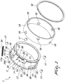
- the friction ring for friction shafts is designated generally by the reference numeral 1 and comprises an internal ring 2 that can be arranged on a friction shaft, generally designated by the reference numeral 3 and typically provided by means of a shaft body 4, which is provided peripherally with a plurality of strips 5 that are extended parallel to the axis and can expand radially by way of the action of expansion chambers 6 that can be connected to a compressed air supply circuit, not shown.
- the strips 5 are made to expand with a pressure value that is variable as a function of the torque that one wishes to impart to the individual cores being rewound, so that the spools can adapt automatically to different traction conditions during winding.
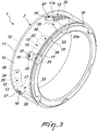
- the internal ring 2 is provided with a central body 10 which is provided, at one end, with a flange 11, which can be coupled to an external ring 15 provided with uniformly distributed openings 16 for the exit of locking elements constituted by balls 17 or, as an alternative, by rollers.
- the openings 16, as an alternative, can be replaced with notches provided on the edges of the external ring.
- the size of the openings is smaller than the diameter of the balls 17 or in any case such as to prevent complete crossing of the respective locking element.
- the balls 17 are activated for their movement in a radial direction by the rotation between the internal ring 2 and the external ring 15.
- the external ring 15 is held in position by means of a spiral locking ring 18 that is inserted in a groove 19 defined correspondingly on the central body 10.
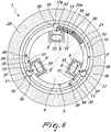
- the external ring 15 and the internal ring 2 are mutually and coaxially rotatable in contrast with elastic means, constituted advantageously by at least one compression spring 30 which acts between the external ring 15 and the internal ring 2, in particular between a tab 21 of a slot 20a and a ball 17a.
- a particularity of the invention is that the balls 17 are adapted to retract radially toward the inside of the external ring 15 as the load on the elastic means, in particular on the compression spring 30, decreases. More specifically, in the rest condition of the compression spring 30, or in a condition in which the spring 30 is subject to a minimal load (i.e., in a stroke limit position 35 of the ball 17a), all the balls 17, 17a are substantially retracted into the respective openings 16, thus allowing free sliding of the core 31 of the spool 29 to be rewound or already rewound, along the friction shaft 3 on which the friction rings 1 according to the invention are fitted, without in any way having to rotate the shaft 3 or impart manually a rotation to the core 31.
- the openings 16 that can be crossed only partially by the balls 17, 17a, when said elastic means are in the inactive condition or minimum load condition, are superimposed on a portion 33 of a respective ramp 20, 20a that is radially more internal than the peak point 34 of said ramp 20, 20a.
- Said portion 33 can include an end wall 35 of the slot 20, while the other stroke limit wall 36 of the ball 17 is adjacent to the peak point 34 of the slot 20.
- the balls 17 are thus completely or almost completely retracted into the friction ring 1 in the situation, when the machine is stationary, in which the cores 31 of the spools 29 must be fitted on the friction shaft 3 that mounts the friction rings 1 according to the invention or in which the rewound spools 31 must be removed from said shaft 3.
- a dome-like portion 37 of each ball 17 can be left protruding toward the outside of the respective opening 16 in order to define a sliding bearing for the core 31 of the spool 29.
- the locking elements constituted by the balls 17, 17a can protrude radially from the external ring 15 to an extent that is sufficient to allow the engagement of the ring 31, which is optionally empty, and its sliding, optionally with the presence of the spool 29, along the friction ring 1 without jamming.
- the shaft 3 is made to rotate about its own axis by way of a motor, not shown, in the direction that allows the rewinding of a tape 38 around a respective core 31.
- the mutual locking between the shaft 3 and the internal ring 2 causes, upon the start of the rotation of the shaft 3, a mutual rotation between the internal ring 2 and the external ring 15 of each friction ring 1 covered by a core 31.
- This mutual rotation loads the compression spring 30 and entrains the balls 17, 17a pushed by the openings 16 in the radially rising direction of the ramps 12.
- the balls 17, 17a protrude accordingly from the respective openings 16 until they lock against the internal surface of the cores 31, thus locking them on the shaft 3.
- the shaft 3 is stopped and the compression spring 30 of each friction ring 1 covered by a core 31 returns to the inactive or minimum load condition, thus causing the balls 17 to retract into the respective openings 16, disengaging them from the cores 31.
- the rewound spools can be extracted from the shaft 3 simply by pushing them in a direction that is parallel to the rotation axis of the shaft 3, without having to rotate it in the opposite direction with respect to the rewinding direction as occurs in the background art, where for this purpose it is necessary to provide a second motor for the shaft.
- the materials used may be any according to requirements and to the state of the art.
Landscapes
- Winding Of Webs (AREA)
- Devices For Conveying Motion By Means Of Endless Flexible Members (AREA)
Claims (4)
- Ein Reibungsring (1) für Friktionswellen, insbesondere zum Wiederaufwickeln von Spulen, der einen inneren Ring (2) umfasst, der auf einer Friktionswelle (3) angebracht werden kann und koaxial mit einem äußeren Ring (15) verbunden ist, aus dem Elemente (17, 17a) zur lösbaren Blockierung des Kerns (31) einer Spule (29) herausragen, die mit der Friktionswelle (3) gekoppelt werden kann, wobei der innere und der äußere Ring (2, 15) im Verhältnis zueinander und koaxial im Kontrast zu elastischen Mitteln (30) drehbar sind,
wobei die Blockierelemente (17, 17a) ausgebildet sind, um sich radial zur Innenseite des äußeren Rings (15) hin zurückzuziehen, wenn die Last auf den elastischen Mitteln (30) abnimmt;
wobei der innere Ring (2) Gleit- oder Rollrampen (12) für entsprechende Blockierelemente (17, 17a) umfasst und der äußere Ring (15) Öffnungen (16) oder Kerben umfasst, die teilweise von den Blockierelementen (17, 17a) durchquert werden können und über die Rampen (12) gelegt sind, wobei die Öffnungen (16) oder Kerben, wenn die elastischen Mittel (30) sich im inaktiven Zustand oder im Zustand minimaler Last befinden, über einem Abschnitt (33) einer entsprechenden Rampe (20, 20a) liegen, der radial weiter innen liegt als ihr Scheitelpunkt, wobei die Rampen (12) an entsprechenden bogenartigen Schlitzen (20) des inneren Rings (2) angebracht sind,
dadurch gekennzeichnet, dass
die elastischen Mittel mindestens eine Druckfeder (30) umfassen, die zwischen dem inneren Ring (2) und dem äußeren Ring (15) arbeitet, so dass im inaktiven Zustand oder im Zustand minimaler Belastung der Druckfeder (30) die Blockierelemente (17, 17a) radial aus dem äußeren Ring (15) in einem Grad herausragen, der ausreicht, um das Gleiten des Kerns (31) der Spule (29) zu ermöglichen, und die elastischen Mittel (30) in mindestens einem der Schlitze (20) untergebracht sind, um zwischen einem der Blockierelemente (17, 17a) und einer Bodenwand des jeweiligen Schlitzes (20) zu wirken. - Der Reibungsring (1) gemäß Anspruch 1, wobei die Blockierelemente (17, 17a) Kugeln oder Rollen sind.
- Der Reibungsring (1) gemäß einem oder mehreren der obigen Ansprüche, wobei die elastischen Mittel (30) in mindestens einem Schlitz (20) untergebracht sind, der in dem zentralen Körper angebracht ist, um zwischen einer Bodenwand des Schlitzes (20) und einem Widerlagerelement zu wirken, das integral mit dem äußeren Ring (15) ist.
- Der Reibungsring (1) gemäß Anspruch 3, wobei das Widerlagerelement ein Anschlag-Gewindestift ist, der mit dem äußeren Ring (15) verschraubt werden kann.
Applications Claiming Priority (1)
| Application Number | Priority Date | Filing Date | Title |
|---|---|---|---|
| ITMI20141488 | 2014-08-12 |
Publications (2)
| Publication Number | Publication Date |
|---|---|
| EP2985253A1 EP2985253A1 (de) | 2016-02-17 |
| EP2985253B1 true EP2985253B1 (de) | 2018-12-05 |
Family
ID=51703266
Family Applications (1)
| Application Number | Title | Priority Date | Filing Date |
|---|---|---|---|
| EP15180337.6A Active EP2985253B1 (de) | 2014-08-12 | 2015-08-10 | Reibungsring für reibungsschäfte, insbesondere zum umwickeln von spulen |
Country Status (2)
| Country | Link |
|---|---|
| EP (1) | EP2985253B1 (de) |
| TR (1) | TR201902834T4 (de) |
Cited By (1)
| Publication number | Priority date | Publication date | Assignee | Title |
|---|---|---|---|---|
| EP4396469A4 (de) * | 2022-10-17 | 2024-11-13 | Reymak Makine Sanayi ve Ticaret Anonim Sirketi | Reibring |
Families Citing this family (1)
| Publication number | Priority date | Publication date | Assignee | Title |
|---|---|---|---|---|
| CN110984055B (zh) * | 2019-12-29 | 2021-06-25 | 山东施卫普环保科技有限公司 | 一种清雪机压辊及用于该压辊的拨盘 |
Citations (2)
| Publication number | Priority date | Publication date | Assignee | Title |
|---|---|---|---|---|
| GB2300460A (en) * | 1995-05-03 | 1996-11-06 | Kampf Gmbh & Co Maschf | Friction coupled core support device |
| JP2012153519A (ja) * | 2011-01-28 | 2012-08-16 | Kataoka Mach Co Ltd | 巻取カラー |
Family Cites Families (7)
| Publication number | Priority date | Publication date | Assignee | Title |
|---|---|---|---|---|
| US4496114A (en) * | 1981-07-22 | 1985-01-29 | Hiroshi Kataoka | Winding shaft provided on surface with spool fixing rollers |
| DE59004646D1 (de) * | 1990-05-26 | 1994-03-24 | Beloit Technologies Inc | Spannkopf für wickelhülsen. |
| DE4244218C1 (de) * | 1992-12-24 | 1994-04-07 | Hans Heuser | Friktionswickelwelle |
| DE19805211A1 (de) * | 1998-02-10 | 1999-08-12 | Schaeffler Waelzlager Ohg | Spannvorrichtung zum Verbinden zweier umeinander angeordneter Bauteile |
| IT1397733B1 (it) * | 2010-01-15 | 2013-01-24 | I E S Internat Expanding Shafts S R L | Anello di frizione per alberi a frizione, particolarmente per il riavvolgimento di bobine. |
| JP5700285B2 (ja) * | 2011-02-09 | 2015-04-15 | 株式会社片岡機械製作所 | 巻取カラー |
| WO2013128479A1 (en) * | 2012-02-27 | 2013-09-06 | I.E.S. International Expanding Shafts S.R.L | Expandable shaft for supporting reels and the like |
-
2015
- 2015-08-10 TR TR2019/02834T patent/TR201902834T4/tr unknown
- 2015-08-10 EP EP15180337.6A patent/EP2985253B1/de active Active
Patent Citations (2)
| Publication number | Priority date | Publication date | Assignee | Title |
|---|---|---|---|---|
| GB2300460A (en) * | 1995-05-03 | 1996-11-06 | Kampf Gmbh & Co Maschf | Friction coupled core support device |
| JP2012153519A (ja) * | 2011-01-28 | 2012-08-16 | Kataoka Mach Co Ltd | 巻取カラー |
Cited By (1)
| Publication number | Priority date | Publication date | Assignee | Title |
|---|---|---|---|---|
| EP4396469A4 (de) * | 2022-10-17 | 2024-11-13 | Reymak Makine Sanayi ve Ticaret Anonim Sirketi | Reibring |
Also Published As
| Publication number | Publication date |
|---|---|
| EP2985253A1 (de) | 2016-02-17 |
| TR201902834T4 (tr) | 2019-03-21 |
Similar Documents
| Publication | Publication Date | Title |
|---|---|---|
| EP2345614B1 (de) | Reibring für Reibwellen, insbesondere zum Aufwickeln von Spulen | |
| US4927286A (en) | Rapid connection between two shafts or the like | |
| EP2985253B1 (de) | Reibungsring für reibungsschäfte, insbesondere zum umwickeln von spulen | |
| JP5797816B1 (ja) | 巻芯支持装置 | |
| CN210865437U (zh) | 锁定组件、卷绕装置和柔性卷绕显示设备 | |
| JP2016114599A (ja) | 時計のための機械式巻上げデバイス | |
| EP2819941A1 (de) | Dehnbare welle zum halten von spulen und dergleichen | |
| EP2745981B1 (de) | Planetengetriebeausrichtung und Indexierverfahren und zugehöriges Werkzeug | |
| US20220041392A1 (en) | Support spindle for windable material coils | |
| JP6955663B2 (ja) | 巻取カラー | |
| EP2860419A2 (de) | Vorrichtung zum gegenseitigen Rückhalten und Ausrücken zwischen einer Welle und der Nabe einer Gelenkgabel | |
| EP1580750A3 (de) | Aufzeichnungsbandkassette | |
| US3738720A (en) | Bearing locking means | |
| EP3553010B1 (de) | Ringvorrichtung für wellen in wickelmaschinen und damit ausgerüstete welle | |
| US3420465A (en) | Core carrying mandrel | |
| EP3705432B1 (de) | Ringförmige vorrichtung mit verbesserter leistung für wellen von wickelmaschinen | |
| WO2017103771A1 (en) | Improved annular locking device for the winding of reels | |
| JP2014234247A (ja) | 巻芯支持装置 | |
| JP4853830B2 (ja) | 押しコップ | |
| JP5950224B1 (ja) | 帯状シート巻軸 | |
| JP4644494B2 (ja) | 直動ワンウェイクラッチ | |
| CN109368320B (zh) | 快速自锁装置及轴系 | |
| JP5765603B1 (ja) | フリクション巻軸 | |
| ITMI20091126A1 (it) | Anello di frizione per alberi espandibili, particolarmente per il riavvolgimento di bobine multiple. | |
| JP2007010000A (ja) | 軸方向ワンウェイクラッチ |
Legal Events
| Date | Code | Title | Description |
|---|---|---|---|
| PUAI | Public reference made under article 153(3) epc to a published international application that has entered the european phase |
Free format text: ORIGINAL CODE: 0009012 |
|
| AK | Designated contracting states |
Kind code of ref document: A1 Designated state(s): AL AT BE BG CH CY CZ DE DK EE ES FI FR GB GR HR HU IE IS IT LI LT LU LV MC MK MT NL NO PL PT RO RS SE SI SK SM TR |
|
| AX | Request for extension of the european patent |
Extension state: BA ME |
|
| 17P | Request for examination filed |
Effective date: 20160812 |
|
| RBV | Designated contracting states (corrected) |
Designated state(s): AL AT BE BG CH CY CZ DE DK EE ES FI FR GB GR HR HU IE IS IT LI LT LU LV MC MK MT NL NO PL PT RO RS SE SI SK SM TR |
|
| STAA | Information on the status of an ep patent application or granted ep patent |
Free format text: STATUS: EXAMINATION IS IN PROGRESS |
|
| 17Q | First examination report despatched |
Effective date: 20171012 |
|
| GRAP | Despatch of communication of intention to grant a patent |
Free format text: ORIGINAL CODE: EPIDOSNIGR1 |
|
| STAA | Information on the status of an ep patent application or granted ep patent |
Free format text: STATUS: GRANT OF PATENT IS INTENDED |
|
| INTG | Intention to grant announced |
Effective date: 20180620 |
|
| GRAS | Grant fee paid |
Free format text: ORIGINAL CODE: EPIDOSNIGR3 |
|
| GRAA | (expected) grant |
Free format text: ORIGINAL CODE: 0009210 |
|
| GRAA | (expected) grant |
Free format text: ORIGINAL CODE: 0009210 |
|
| STAA | Information on the status of an ep patent application or granted ep patent |
Free format text: STATUS: THE PATENT HAS BEEN GRANTED |
|
| AK | Designated contracting states |
Kind code of ref document: B1 Designated state(s): AL AT BE BG CH CY CZ DE DK EE ES FI FR GB GR HR HU IE IS IT LI LT LU LV MC MK MT NL NO PL PT RO RS SE SI SK SM TR |
|
| REG | Reference to a national code |
Ref country code: GB Ref legal event code: FG4D |
|
| REG | Reference to a national code |
Ref country code: CH Ref legal event code: EP |
|
| REG | Reference to a national code |
Ref country code: AT Ref legal event code: REF Ref document number: 1072783 Country of ref document: AT Kind code of ref document: T Effective date: 20181215 |
|
| REG | Reference to a national code |
Ref country code: IE Ref legal event code: FG4D |
|
| REG | Reference to a national code |
Ref country code: DE Ref legal event code: R096 Ref document number: 602015020749 Country of ref document: DE |
|
| REG | Reference to a national code |
Ref country code: NL Ref legal event code: MP Effective date: 20181205 |
|
| REG | Reference to a national code |
Ref country code: AT Ref legal event code: MK05 Ref document number: 1072783 Country of ref document: AT Kind code of ref document: T Effective date: 20181205 |
|
| REG | Reference to a national code |
Ref country code: LT Ref legal event code: MG4D |
|
| PG25 | Lapsed in a contracting state [announced via postgrant information from national office to epo] |
Ref country code: ES Free format text: LAPSE BECAUSE OF FAILURE TO SUBMIT A TRANSLATION OF THE DESCRIPTION OR TO PAY THE FEE WITHIN THE PRESCRIBED TIME-LIMIT Effective date: 20181205 Ref country code: LV Free format text: LAPSE BECAUSE OF FAILURE TO SUBMIT A TRANSLATION OF THE DESCRIPTION OR TO PAY THE FEE WITHIN THE PRESCRIBED TIME-LIMIT Effective date: 20181205 Ref country code: AT Free format text: LAPSE BECAUSE OF FAILURE TO SUBMIT A TRANSLATION OF THE DESCRIPTION OR TO PAY THE FEE WITHIN THE PRESCRIBED TIME-LIMIT Effective date: 20181205 Ref country code: FI Free format text: LAPSE BECAUSE OF FAILURE TO SUBMIT A TRANSLATION OF THE DESCRIPTION OR TO PAY THE FEE WITHIN THE PRESCRIBED TIME-LIMIT Effective date: 20181205 Ref country code: NO Free format text: LAPSE BECAUSE OF FAILURE TO SUBMIT A TRANSLATION OF THE DESCRIPTION OR TO PAY THE FEE WITHIN THE PRESCRIBED TIME-LIMIT Effective date: 20190305 Ref country code: LT Free format text: LAPSE BECAUSE OF FAILURE TO SUBMIT A TRANSLATION OF THE DESCRIPTION OR TO PAY THE FEE WITHIN THE PRESCRIBED TIME-LIMIT Effective date: 20181205 Ref country code: BG Free format text: LAPSE BECAUSE OF FAILURE TO SUBMIT A TRANSLATION OF THE DESCRIPTION OR TO PAY THE FEE WITHIN THE PRESCRIBED TIME-LIMIT Effective date: 20190305 Ref country code: HR Free format text: LAPSE BECAUSE OF FAILURE TO SUBMIT A TRANSLATION OF THE DESCRIPTION OR TO PAY THE FEE WITHIN THE PRESCRIBED TIME-LIMIT Effective date: 20181205 |
|
| PG25 | Lapsed in a contracting state [announced via postgrant information from national office to epo] |
Ref country code: RS Free format text: LAPSE BECAUSE OF FAILURE TO SUBMIT A TRANSLATION OF THE DESCRIPTION OR TO PAY THE FEE WITHIN THE PRESCRIBED TIME-LIMIT Effective date: 20181205 Ref country code: GR Free format text: LAPSE BECAUSE OF FAILURE TO SUBMIT A TRANSLATION OF THE DESCRIPTION OR TO PAY THE FEE WITHIN THE PRESCRIBED TIME-LIMIT Effective date: 20190306 Ref country code: SE Free format text: LAPSE BECAUSE OF FAILURE TO SUBMIT A TRANSLATION OF THE DESCRIPTION OR TO PAY THE FEE WITHIN THE PRESCRIBED TIME-LIMIT Effective date: 20181205 Ref country code: AL Free format text: LAPSE BECAUSE OF FAILURE TO SUBMIT A TRANSLATION OF THE DESCRIPTION OR TO PAY THE FEE WITHIN THE PRESCRIBED TIME-LIMIT Effective date: 20181205 |
|
| PG25 | Lapsed in a contracting state [announced via postgrant information from national office to epo] |
Ref country code: NL Free format text: LAPSE BECAUSE OF FAILURE TO SUBMIT A TRANSLATION OF THE DESCRIPTION OR TO PAY THE FEE WITHIN THE PRESCRIBED TIME-LIMIT Effective date: 20181205 |
|
| PG25 | Lapsed in a contracting state [announced via postgrant information from national office to epo] |
Ref country code: PT Free format text: LAPSE BECAUSE OF FAILURE TO SUBMIT A TRANSLATION OF THE DESCRIPTION OR TO PAY THE FEE WITHIN THE PRESCRIBED TIME-LIMIT Effective date: 20190405 Ref country code: PL Free format text: LAPSE BECAUSE OF FAILURE TO SUBMIT A TRANSLATION OF THE DESCRIPTION OR TO PAY THE FEE WITHIN THE PRESCRIBED TIME-LIMIT Effective date: 20181205 Ref country code: CZ Free format text: LAPSE BECAUSE OF FAILURE TO SUBMIT A TRANSLATION OF THE DESCRIPTION OR TO PAY THE FEE WITHIN THE PRESCRIBED TIME-LIMIT Effective date: 20181205 |
|
| PG25 | Lapsed in a contracting state [announced via postgrant information from national office to epo] |
Ref country code: RO Free format text: LAPSE BECAUSE OF FAILURE TO SUBMIT A TRANSLATION OF THE DESCRIPTION OR TO PAY THE FEE WITHIN THE PRESCRIBED TIME-LIMIT Effective date: 20181205 Ref country code: IS Free format text: LAPSE BECAUSE OF FAILURE TO SUBMIT A TRANSLATION OF THE DESCRIPTION OR TO PAY THE FEE WITHIN THE PRESCRIBED TIME-LIMIT Effective date: 20190405 Ref country code: SK Free format text: LAPSE BECAUSE OF FAILURE TO SUBMIT A TRANSLATION OF THE DESCRIPTION OR TO PAY THE FEE WITHIN THE PRESCRIBED TIME-LIMIT Effective date: 20181205 Ref country code: EE Free format text: LAPSE BECAUSE OF FAILURE TO SUBMIT A TRANSLATION OF THE DESCRIPTION OR TO PAY THE FEE WITHIN THE PRESCRIBED TIME-LIMIT Effective date: 20181205 Ref country code: SM Free format text: LAPSE BECAUSE OF FAILURE TO SUBMIT A TRANSLATION OF THE DESCRIPTION OR TO PAY THE FEE WITHIN THE PRESCRIBED TIME-LIMIT Effective date: 20181205 |
|
| REG | Reference to a national code |
Ref country code: DE Ref legal event code: R097 Ref document number: 602015020749 Country of ref document: DE |
|
| PLBE | No opposition filed within time limit |
Free format text: ORIGINAL CODE: 0009261 |
|
| STAA | Information on the status of an ep patent application or granted ep patent |
Free format text: STATUS: NO OPPOSITION FILED WITHIN TIME LIMIT |
|
| PG25 | Lapsed in a contracting state [announced via postgrant information from national office to epo] |
Ref country code: SI Free format text: LAPSE BECAUSE OF FAILURE TO SUBMIT A TRANSLATION OF THE DESCRIPTION OR TO PAY THE FEE WITHIN THE PRESCRIBED TIME-LIMIT Effective date: 20181205 Ref country code: DK Free format text: LAPSE BECAUSE OF FAILURE TO SUBMIT A TRANSLATION OF THE DESCRIPTION OR TO PAY THE FEE WITHIN THE PRESCRIBED TIME-LIMIT Effective date: 20181205 |
|
| 26N | No opposition filed |
Effective date: 20190906 |
|
| REG | Reference to a national code |
Ref country code: DE Ref legal event code: R119 Ref document number: 602015020749 Country of ref document: DE |
|
| PG25 | Lapsed in a contracting state [announced via postgrant information from national office to epo] |
Ref country code: CH Free format text: LAPSE BECAUSE OF NON-PAYMENT OF DUE FEES Effective date: 20190831 Ref country code: LU Free format text: LAPSE BECAUSE OF NON-PAYMENT OF DUE FEES Effective date: 20190810 Ref country code: LI Free format text: LAPSE BECAUSE OF NON-PAYMENT OF DUE FEES Effective date: 20190831 Ref country code: MC Free format text: LAPSE BECAUSE OF FAILURE TO SUBMIT A TRANSLATION OF THE DESCRIPTION OR TO PAY THE FEE WITHIN THE PRESCRIBED TIME-LIMIT Effective date: 20181205 |
|
| REG | Reference to a national code |
Ref country code: BE Ref legal event code: MM Effective date: 20190831 |
|
| PG25 | Lapsed in a contracting state [announced via postgrant information from national office to epo] |
Ref country code: FR Free format text: LAPSE BECAUSE OF NON-PAYMENT OF DUE FEES Effective date: 20190831 Ref country code: DE Free format text: LAPSE BECAUSE OF NON-PAYMENT OF DUE FEES Effective date: 20200303 Ref country code: IE Free format text: LAPSE BECAUSE OF NON-PAYMENT OF DUE FEES Effective date: 20190810 |
|
| PG25 | Lapsed in a contracting state [announced via postgrant information from national office to epo] |
Ref country code: BE Free format text: LAPSE BECAUSE OF NON-PAYMENT OF DUE FEES Effective date: 20190831 |
|
| PG25 | Lapsed in a contracting state [announced via postgrant information from national office to epo] |
Ref country code: CY Free format text: LAPSE BECAUSE OF FAILURE TO SUBMIT A TRANSLATION OF THE DESCRIPTION OR TO PAY THE FEE WITHIN THE PRESCRIBED TIME-LIMIT Effective date: 20181205 |
|
| PG25 | Lapsed in a contracting state [announced via postgrant information from national office to epo] |
Ref country code: HU Free format text: LAPSE BECAUSE OF FAILURE TO SUBMIT A TRANSLATION OF THE DESCRIPTION OR TO PAY THE FEE WITHIN THE PRESCRIBED TIME-LIMIT; INVALID AB INITIO Effective date: 20150810 Ref country code: MT Free format text: LAPSE BECAUSE OF FAILURE TO SUBMIT A TRANSLATION OF THE DESCRIPTION OR TO PAY THE FEE WITHIN THE PRESCRIBED TIME-LIMIT Effective date: 20181205 |
|
| PG25 | Lapsed in a contracting state [announced via postgrant information from national office to epo] |
Ref country code: MK Free format text: LAPSE BECAUSE OF FAILURE TO SUBMIT A TRANSLATION OF THE DESCRIPTION OR TO PAY THE FEE WITHIN THE PRESCRIBED TIME-LIMIT Effective date: 20181205 |
|
| P01 | Opt-out of the competence of the unified patent court (upc) registered |
Effective date: 20230527 |
|
| PGFP | Annual fee paid to national office [announced via postgrant information from national office to epo] |
Ref country code: TR Payment date: 20250805 Year of fee payment: 11 Ref country code: IT Payment date: 20250620 Year of fee payment: 11 |
|
| PGFP | Annual fee paid to national office [announced via postgrant information from national office to epo] |
Ref country code: GB Payment date: 20250721 Year of fee payment: 11 |