EP2985536B1 - Procédé de réglage pour un groupe motopompe - Google Patents
Procédé de réglage pour un groupe motopompe Download PDFInfo
- Publication number
- EP2985536B1 EP2985536B1 EP14181144.8A EP14181144A EP2985536B1 EP 2985536 B1 EP2985536 B1 EP 2985536B1 EP 14181144 A EP14181144 A EP 14181144A EP 2985536 B1 EP2985536 B1 EP 2985536B1
- Authority
- EP
- European Patent Office
- Prior art keywords
- error signal
- control method
- limit value
- pump assembly
- speed
- Prior art date
- Legal status (The legal status is an assumption and is not a legal conclusion. Google has not performed a legal analysis and makes no representation as to the accuracy of the status listed.)
- Active
Links
- 238000000034 method Methods 0.000 title claims description 32
- 238000012545 processing Methods 0.000 claims description 37
- 230000001419 dependent effect Effects 0.000 claims description 18
- 238000005265 energy consumption Methods 0.000 claims description 10
- 230000008859 change Effects 0.000 claims description 7
- 238000013459 approach Methods 0.000 claims description 4
- 230000000694 effects Effects 0.000 claims description 2
- 230000001105 regulatory effect Effects 0.000 description 28
- 230000033228 biological regulation Effects 0.000 description 11
- 238000010438 heat treatment Methods 0.000 description 8
- XLYOFNOQVPJJNP-UHFFFAOYSA-N water Substances O XLYOFNOQVPJJNP-UHFFFAOYSA-N 0.000 description 8
- 238000001816 cooling Methods 0.000 description 4
- 238000011144 upstream manufacturing Methods 0.000 description 4
- 238000012913 prioritisation Methods 0.000 description 3
- 230000006978 adaptation Effects 0.000 description 2
- 238000004378 air conditioning Methods 0.000 description 2
- 230000000712 assembly Effects 0.000 description 2
- 238000000429 assembly Methods 0.000 description 2
- 230000008901 benefit Effects 0.000 description 2
- 230000001276 controlling effect Effects 0.000 description 2
- 230000007423 decrease Effects 0.000 description 2
- 230000003247 decreasing effect Effects 0.000 description 2
- 238000005457 optimization Methods 0.000 description 2
- 238000005086 pumping Methods 0.000 description 2
- 238000012546 transfer Methods 0.000 description 2
- 238000009423 ventilation Methods 0.000 description 2
- PZZOEXPDTYIBPI-UHFFFAOYSA-N 2-[[2-(4-hydroxyphenyl)ethylamino]methyl]-3,4-dihydro-2H-naphthalen-1-one Chemical compound C1=CC(O)=CC=C1CCNCC1C(=O)C2=CC=CC=C2CC1 PZZOEXPDTYIBPI-UHFFFAOYSA-N 0.000 description 1
- 238000004364 calculation method Methods 0.000 description 1
- 238000013461 design Methods 0.000 description 1
- 238000001514 detection method Methods 0.000 description 1
- 239000012530 fluid Substances 0.000 description 1
- 230000009467 reduction Effects 0.000 description 1
- 230000004044 response Effects 0.000 description 1
- 238000010187 selection method Methods 0.000 description 1
- 230000002123 temporal effect Effects 0.000 description 1
Images



Classifications
-
- F—MECHANICAL ENGINEERING; LIGHTING; HEATING; WEAPONS; BLASTING
- F04—POSITIVE - DISPLACEMENT MACHINES FOR LIQUIDS; PUMPS FOR LIQUIDS OR ELASTIC FLUIDS
- F04B—POSITIVE-DISPLACEMENT MACHINES FOR LIQUIDS; PUMPS
- F04B49/00—Control, e.g. of pump delivery, or pump pressure of, or safety measures for, machines, pumps, or pumping installations, not otherwise provided for, or of interest apart from, groups F04B1/00 - F04B47/00
- F04B49/06—Control using electricity
- F04B49/065—Control using electricity and making use of computers
-
- F—MECHANICAL ENGINEERING; LIGHTING; HEATING; WEAPONS; BLASTING
- F04—POSITIVE - DISPLACEMENT MACHINES FOR LIQUIDS; PUMPS FOR LIQUIDS OR ELASTIC FLUIDS
- F04D—NON-POSITIVE-DISPLACEMENT PUMPS
- F04D15/00—Control, e.g. regulation, of pumps, pumping installations or systems
- F04D15/0066—Control, e.g. regulation, of pumps, pumping installations or systems by changing the speed, e.g. of the driving engine
-
- F—MECHANICAL ENGINEERING; LIGHTING; HEATING; WEAPONS; BLASTING
- F04—POSITIVE - DISPLACEMENT MACHINES FOR LIQUIDS; PUMPS FOR LIQUIDS OR ELASTIC FLUIDS
- F04B—POSITIVE-DISPLACEMENT MACHINES FOR LIQUIDS; PUMPS
- F04B49/00—Control, e.g. of pump delivery, or pump pressure of, or safety measures for, machines, pumps, or pumping installations, not otherwise provided for, or of interest apart from, groups F04B1/00 - F04B47/00
- F04B49/20—Control, e.g. of pump delivery, or pump pressure of, or safety measures for, machines, pumps, or pumping installations, not otherwise provided for, or of interest apart from, groups F04B1/00 - F04B47/00 by changing the driving speed
-
- F—MECHANICAL ENGINEERING; LIGHTING; HEATING; WEAPONS; BLASTING
- F24—HEATING; RANGES; VENTILATING
- F24D—DOMESTIC- OR SPACE-HEATING SYSTEMS, e.g. CENTRAL HEATING SYSTEMS; DOMESTIC HOT-WATER SUPPLY SYSTEMS; ELEMENTS OR COMPONENTS THEREFOR
- F24D19/00—Details
- F24D19/10—Arrangement or mounting of control or safety devices
- F24D19/1006—Arrangement or mounting of control or safety devices for water heating systems
- F24D19/1009—Arrangement or mounting of control or safety devices for water heating systems for central heating
- F24D19/1012—Arrangement or mounting of control or safety devices for water heating systems for central heating by regulating the speed of a pump
-
- Y—GENERAL TAGGING OF NEW TECHNOLOGICAL DEVELOPMENTS; GENERAL TAGGING OF CROSS-SECTIONAL TECHNOLOGIES SPANNING OVER SEVERAL SECTIONS OF THE IPC; TECHNICAL SUBJECTS COVERED BY FORMER USPC CROSS-REFERENCE ART COLLECTIONS [XRACs] AND DIGESTS
- Y02—TECHNOLOGIES OR APPLICATIONS FOR MITIGATION OR ADAPTATION AGAINST CLIMATE CHANGE
- Y02B—CLIMATE CHANGE MITIGATION TECHNOLOGIES RELATED TO BUILDINGS, e.g. HOUSING, HOUSE APPLIANCES OR RELATED END-USER APPLICATIONS
- Y02B30/00—Energy efficient heating, ventilation or air conditioning [HVAC]
- Y02B30/70—Efficient control or regulation technologies, e.g. for control of refrigerant flow, motor or heating
Definitions
- the invention relates to a control method for a pump unit in a pneumatic or hydraulic system and a pump system, which is designed for carrying out such a control method.
- branched hydraulic systems such as multi-user heating systems or multiple-use water supply systems
- the control method according to the invention is used for at least one pump unit in a pneumatic or hydraulic system.
- a hydraulic system may for example be a water supply network or a heating system, in particular with a large number of consumers.
- valves for adjusting or regulating the flow for the respective consumer can be provided at the various consumers.
- the invention will be further described with reference to a hydraulic system, but it should be understood that the invention may also be used in a pneumatic system, such as a ventilation system, such as a heating or air conditioning system using tempered air. It is also to be understood that when the invention is described below using the example of a heating system, the invention can be implemented in a corresponding manner in other hydraulic systems, such as air conditioning systems or water supply systems.
- the rotational speed of the at least one pump unit can be regulated as a function of a plurality of variables detected in the system.
- a single pump unit can be provided, but it can Also, several, parallel and / or series-connected pump units may be provided, which can be controlled in a corresponding manner.
- the detected variables are not directly based on the control, but that an error signal is generated from the plurality of detected variables based on a piecewise or partially monotonous function, several error signals are added and based on the added error signals, the speed of the pump unit is regulated so that the added error signal approaches zero.
- a function which is monotonic in sections is understood to mean a function which is composed of at least two functions or sections with different functional properties. The function is monotone in all sections. This partially monotone function means, for example, that different functions are used to calculate the error signals for different size ranges of the detected variables.
- error signals has the advantage that they can be more easily incorporated into the control of the pump unit, since the error signals can be adjusted via the function so that the control of the pump unit several error signals are based, which regardless of the exact design of the hydraulic system and whose components are. This allows a simple adaptation and in particular a simpler control of the pump unit based on a plurality of error signals, since they can be added together in a simple manner.
- Each variable can be detected in the system by suitable sensors or can be directly taken off or output by actuators, such as valves, as characteristic of their functional state.
- each of the plurality of variables is, for example, a pressure value or valve opening degree detected in the system.
- the valve opening degree can be tapped directly on the valve or a control signal for the valve, which is the valve opening degree proportional to be.
- a separate pressure sensor may be arranged in the hydraulic or pneumatic system.
- the plurality of variables may each be a temperature value or flow value detected in the system.
- suitable sensors can also be provided in the system.
- a flow value can also be derived, for example, directly from a further pump unit arranged in the system, by determining it there on the basis of other variables detected in the pump unit, in particular the rotational speed of the pump unit.
- these may be a plurality of pressure values, a plurality of valve opening degrees, a plurality of temperature values or a plurality of flow values. It is also possible to detect various values in combination, wherein an error signal is output for each variable on the basis of the said section-wise monotonous function.
- the calculation or output of the error signal has the advantage that in a simple manner in the control of the pump unit various variables, such as valve opening degrees and detected temperature values can be incorporated.
- the detected variable for calculating the error signal is compared with at least one limit value, and upon reaching the limit value, the function is changed in a predetermined manner from the group of functions on the basis of which the error signal is generated.
- the limit forms the boundary between two sections or functions of the section-wise monotonic function. That is, for various predetermined size ranges
- the variable is provided with various functions for determining the error signal.
- two interlinked functions or sections of the sections monotonous function may be provided, wherein a first function z. B. below the limit and a second function z. B. is used when reaching and exceeding the limit. Accordingly, more than two functions or sections can be used, which are changed at corresponding limits.
- the detected variable can be compared with an upper and a lower limit value, and when the upper limit value is reached and the lower limit value is reached, the section of the partially monotonic function or the function of the group of functions on the basis of which the error signal is generated will be changed in a predetermined manner.
- the section of the partially monotonic function or the function of the group of functions on the basis of which the error signal is generated will be changed in a predetermined manner.
- three different functions or sections may be used, with a first function below the lower limit, a second function between the lower and upper limits, and a third function above the upper limit.
- the functions which are used above the upper limit value and / or below the lower limit value emit an error signal dependent on the size of the detected variables, in particular a linearly dependent error signal.
- the same function can also be used below the lower limit value and above the upper limit value.
- a function may be used which is one of the size of the variables dependent, in particular linearly dependent error signal outputs, wherein the function between variable and error signal above and below the respective limit value are different, in particular have different slopes.
- a lower slope function may be used than above the upper and lower limits.
- the function in a region above the lower limit value and below the upper limit value, may have a zero point with a change of sign.
- the zero is preferably midway between the upper and lower limits.
- the error signal would thus be zero.
- the error signal which is output when the upper limit value is reached and above the upper limit value can have a different sign than the error signal which is output when the lower limit value is reached or exceeded. This allows a control which helps keep the variable in the range between the upper and lower limits.
- a function or a section of the partially monotonous function may be several of the functions or sections used Also be designed so that they output a constant value, in particular the value zero for the error signal. For example, above or below a threshold, the function may be selected to output such a constant value.
- the generation of the error signal can be carried out in a signal processing device assigned in a sensor for detecting the variables, and the generated error signal can be transmitted to a regulating device of the pump unit which effects the regulation of the rotational speed of the pump unit.
- the signal processing device may be specially adapted to the respective sensor or the actuating element, for example a valve, so that it contains the appropriate or desired functions which the characteristic properties of the sensor or the region of the hydraulic system, to which the variable is detected , considered.
- the error signal can be adapted to the used control unit of the pump unit, so that a standardized error signal is output.
- the functions in the signal processing device can be adaptable or adjustable.
- the signal processing device can be integrated directly into the sensor or the control element as a valve.
- the signal processing device can also be designed as a separate component, which is supplied as an input variable, the output signal of a sensor or an actuating element such as a valve. It is also possible to provide a signal processing device which operates a plurality of sensors or control elements such as valves and accordingly several error signals for the connected sensors or control elements outputs.
- the system is designed such that a plurality of variables are detected, based on which an error signal is respectively generated on the basis of a group of at least two functions that are linked to one another or a partially monotonous function.
- an error signal is generated for each of the variables by a corresponding section-wise monotonic function. Since the error signals are preferably standardized as described above and the adaptation to the respective sensors or regions of the system in which the sensors are arranged takes place via the respective functions, this makes it possible to use various sensors or control elements such as valves Capture or output variables, combine them in a system without any problems and incorporate them into the control of the pump set.
- the regulation of the speed of the pump unit is based on the added error signals.
- the regulation of the rotational speed of the pump assembly takes place so that the added error signal approaches zero.
- the various error signals are linked and the speed of the pump set regulated so that in all areas of the system in which variables are detected and based on error signals are determined, the desired hydraulic setpoints, be it pressure, temperature, Flow and / or for example a valve opening degree, etc. can be achieved.
- the individual error signals may be multiplied by individual weighting factors prior to addition. This multiplication can also take place in the previously described signal processing device or else in a control device of the pump unit.
- the weighting factors differentially weight the error signals of individual components in the system, so that, for example, certain valves or sections of the system can be given greater weight in the regulation of the pump unit in order, for example, to prioritize a required flow in this area.
- a weighting or a prioritization of the error signals may possibly also take place.
- individual error signals can be assigned a priority for the selection.
- error signals are added as described above and also optionally multiplied by weighting factors previously.
- the speed of the pump assembly is preferably controlled in response to a differential pressure or flow, and the differential pressure or flow rate is regulated based on one or more error signals.
- the desired differential pressure or flow is first selected, and then the control of the pump unit is performed so that this differential pressure or flow rate is achieved by the pump unit.
- the speed of the pump unit can be varied by a control device of the pump unit.
- the speed of the pump unit can be changed depending on the error signal directly or indirectly in predetermined steps. If the error signal z. B. for determining the differential pressure or flow, which is to reach the pump unit, as described above, is used, this would be an indirect specification of the speed.
- the error signal By the error signal, a continuous adjustment of the speed can be carried out directly or indirectly, or an adjustment in predetermined steps in which the speed is increased or decreased to achieve a desired flow and / or differential pressure or directly minimizing an error signal.
- the rotational speed of the at least one pump assembly is regulated in addition to the error signal on the basis of an algorithm for minimizing power consumption or energy consumption.
- These two algorithms may be interlinked or superimposed, so that pump control always seeks to minimize power consumption as long as the error signals are kept to a minimum value, or ideally zero. If error signals are fed to the controller, this possibly leads to a change in the rotational speed of the pump assembly, which is opposite to minimizing the energy consumption. This then takes place until the hydraulic parameters of the system are kept within the desired limits by detection at the respective sensors. Thus, if minimization of energy consumption occurs at the same time, it is achieved that the hydraulic setpoints can be achieved with minimum energy consumption.
- the algorithm for minimizing the energy consumption is preferably designed in such a way that it endeavors to increase the speed of the To reduce pumping units. If the reduction in the speed then causes individual sensors or control elements to output error signals, these error signals cause, for example, error signals. B. again an increase in speed, so that the hydraulic setpoints can be achieved.
- the subject of the invention is also a pump system.
- the pump system according to the invention has at least one sensor for detecting a variable in a hydraulic or pneumatic system.
- the sensor may be a sensor as described above, which detects, for example, temperature, flow and / or pressure.
- the sensor may be designed as a separate sensor or be part of an actuating device, such as a valve or a pump unit.
- the sensor can detect and output the valve opening degree.
- an adjusting device such as a valve, which detects or outputs the degree of opening in a different way, is also understood.
- the flow can also be detected or determined and output in the sense of a sensor.
- the pump system has at least one pump unit with a control device, which is designed to receive the at least one error signal from the signal processing device and to regulate the pump unit on the basis of the at least one error signal.
- the control device and the signal processing device are designed to carry out a control method as described above.
- the signal processing device and the control device are preferably spaced from each other spatially, but may optionally also be integrated into an electronic assembly.
- the signal processing device is arranged in the vicinity of the sensor, in particular integrated in this, while the control device is preferably arranged in the vicinity of the pump unit, preferably arranged in an electronics housing directly on the drive motor of the pump unit.
- FIGS. 1 to 7 Various variants of hydraulic systems are described in which a control method according to the invention, as described below, can be used. It is to be understood that this principle can be transferred from hydraulic systems in the same way to pneumatic systems, for example ventilation systems, which are also the subject of the invention.
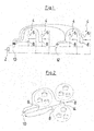
- Fig. 1 shows a heating and / or cooling system with a heat or cold source 2, which in the case of a heat source, for example as Boiler can be formed.
- the system shown has several, in this example four load circuits 4, which are equipped as mixer circuits, each with a mixer pump 6 and a regulating valve 8.
- the supply of heat transfer medium from the heat or cold source 2 is controlled in the respective load circuit 4. This can be done, for example, room temperature dependent to reach a predetermined room temperature.
- two pump units 10, 12 are arranged in the form of Umisselzpumpenaggregaten, which promote the heat transfer medium, such as water, from the heat or cold source 2 to the load circuits 4.
- the pump unit 10 is located upstream of all four load circuits, while the second pump unit 12 is located downstream of the first two load circuits and upstream of the subsequent two load circuits 4.
- the regulating valves 8 are designed to detect the valve opening degree and generate in a signal processing device, as will be explained below, an error signal which is transmitted to the pump units 10 and 12 for their speed control.
- Fig.1 shown by the dashed lines, it being understood that the error signals of all four regulating valves 8 are transmitted to the first pump unit 10, while the error signals of the two downstream load circuits 4 are transmitted only to the second pump unit 12, which only for the supply of these two Load circuits 4 is provided.
- This in Fig. 2 shown hydraulic system is a water supply network, with a pump unit 10 and three regulating valves 8.
- the regulating valves 8 can operate as a pressure regulator to regulate the pressure in the subsequent branches of the hydraulic system.
- the pump unit 10 conveys into a central supply line 14, branch off from which branches with the regulating valves 8, for example, in each case for the supply of several buildings, z. B. in a district.
- the pressure in these parts or branches is regulated.
- These regulating valves 8 also output their valve opening degree, on the basis of which, as will be described below, an error signal is generated in a signal processing device, which is transmitted to the pump unit 10 in order to regulate its rotational speed on the basis of these error signals.
- the pump unit can be, for example, a booster pump or a booster pump arrangement, as used in particular in a water supply network.
- Fig. 3 shows a variant of the embodiment in Fig. 2 in which the supply line 14 is formed as a loop line.
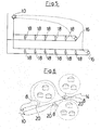
- Fig. 4 shows a variant of the hydraulic system in Fig. 1 in which the valve opening degree of the regulating valve 8 is not detected in the load circuits 4, but the differential pressure Dp between the input of the load circuit 4 and its output is detected via a differential pressure sensor 16. On the basis of this differential pressure, an error signal is generated in a connected, preferably in the differential pressure sensor 16 integrated signal processing device, which is then output to the pump units 10, 12 to the speed control.
- the error signals of the differential pressure sensors 16 are based on all four load circuits of the regulation of the rotational speed of the first upstream pump unit 10, while the speed regulation of the second downstream pump unit 12 are based only on the error signals of those differential pressure sensors 16, which are arranged in the load circuits 4, the downstream the second pump unit 12 are located.
- Fig. 5 shows a hydraulic system in which a plurality of consumers 18, such as radiators, in two mutually parallel branches are each arranged parallel to each other.
- the two branches connected in parallel are supplied with fluid, for example heating medium in the form of water, by a common pump unit 10 in the form of a circulation pump unit.
- a differential pressure sensor 16 is arranged, which detects the differential pressure Dp between the inlet and outlet of the respective branch at the end of the branch.
- the differential pressure sensors 16 issue via signal processing means, as described below, again error signals, which are supplied to the pump unit 10 to the speed control.
- Fig. 6 shows a water supply network, as in Fig. 2 is shown, except that here the valve opening degree of the valves 8 is not detected, but in the branches, in which the regulating valves 8 are located, pressure sensors 20 are arranged, which detect the pressure p in these branches. In an appropriate signal processing device, an error signal is generated in each case on the basis of the detected pressure p, as will be described below, and forwarded to the pump unit 10 for its speed control.
- Fig. 7 shows a hydraulic system similar to the hydraulic system in Fig. 1 , wherein instead of the load circuits 4 more consumers 22, for example, as a heat exchanger in a room or building are available.
- the system may be, for example, a heating or cooling system, in which case the heat or cooling source 2 is shown as a heat exchanger.
- a temperature sensor 24 is arranged in each case, which detects a temperature T, that is, the return temperature T r of the respective consumer 22.
- a signal processing device On the basis of the temperature signals of the temperature sensors 24, as will be described below, in a signal processing device generates an error signal in each case, which is forwarded to the pump units 10 and 12 to the speed control.
- the speed regulation of the first upstream pump unit 10 based on the error signals of all downstream temperature sensors 24, while the speed regulation of the pump unit 12 is based only on the error signals of those temperature sensors 24, which are located downstream of the second pump unit 12.
- the pump units 10 and 12 each have their own control or regulating device, which is particularly preferably arranged in a terminal box or electronics housing directly in the pump unit or on its electric drive motor.
- the signal processing devices for generating the error signals are preferably integrated into the sensors, that is to say the regulating valves 8, if these detect the valve opening degree, the pressure sensors 16, 22 or the temperature sensors 24.
- the signal processing devices may be formed as separate assemblies, which are preferably separate from the pump assemblies 10, 12.
- the signal processing devices make it possible for almost any sensors and valves or adjusting elements which detect their output level, for example a valve opening degree, to be linked to the pump unit 10, 12.
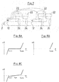
- Figs. 8A-8C show three examples of the generation of an error signal e based on a valve opening degree x p , which for example is detected and output from the above-described regulating valves 8.
- a limit value for the valve opening degree x p, max which represents an upper limit value
- the function of a constant here the value zero.
- the desired operating point for the respective regulating valve 8, for which the valve opening degrees are output lies in this example between the limits x p, min and x p, max , so that the error signal e is designed such that the control endeavors to move the pump unit 10 resp to regulate the pump unit 12 in its rotational speed so that the regulating valve 8 assumes the desired operating point, ie a valve opening degree x p , which is situated between the limit values x p, min and x p, max .
- valve opening degree x p is preferably controlled via an independent control, for example in a heating system via a room thermostat.
- Fig. 8B shows a variant to the group of functions according to Fig. 8A in which the lower limit value x p, min and thus the third function, which is below the limit value x p, min is used, is dispensed with. This means that when the upper limit value x p, max is undershot , a constant value of zero is always output for the error signal e.
- Fig. 8C shows a further variant in which the functions for the area below the lower limit x p, min and above the upper limit x p, max correspond to those which by means of Fig. 8A have been described. Only between the two limits x p, min and x p, max , a function is used here, which outputs no constant value zero for the error signal e, but also one of the valve opening degree x p linearly dependent error signal e with a sign change at the valve opening degree x p, M , which in this example is located midway between the lower and upper limits. The slope of the curve for the error signal e between the lower limit x p, min and the upper limit x p, max is less than the slope above and below these limits. In such a control, an error signal e is output so that it is achieved via the speed control of the pump units 10 and 12 that the valve opening degree x p is preferably maintained in the range of the mean value x p, M.
- Figs. 9A-9C now show three similar examples of the output of an error signal e based on a differential pressure Dp, as for example according to the embodiments in Fig. 4 and 5 is detected.
- the embodiment according to Fig. 9B corresponds to the embodiment according to Fig. 9A , wherein the third function for the range above Dp max is omitted, that is, there is no upper limit Dp max . Instead, a constant error signal e with the value zero is always output above the lower limit value Dp min .
- Fig. 9C is similar to the embodiment according to Fig. 8C between the limits Dp min and Dp max also output a linearly dependent on the detected differential pressure Dp error signal e, the error signal e at the value Dp, M has a zero.
- the mean value Dp, M lies in the middle between the limits Dp min and Dp max .
- This control is suitable for substantially regulating the differential pressure to the mean value Dp, M by outputting a corresponding error signal e, if the differential pressure deviates from this value.
- This error signal e then in turn influences the speed of the pump unit.
- the error signal e is output on the basis of a detected temperature value.
- the temperature value is determined, for example, in the example explained above Fig. 7 detected in which the hydraulic system is a cooling system.
- the detected temperature value T is a return temperature value T r .
- the embodiment according to Fig. 10B differs from the embodiment according to Fig. 10A in that the first equation for the range below the lower limit T r, min is omitted, that is, there are only two functions. Above the limit value T r, max , the linearly dependent function is used for the error signal e, as described above has been described. Below the value T r, max , a constant error signal e with the value zero is output.
- a function is used according to which the error signal e is likewise linearly dependent on the detected temperature value T r , the slope of this function being lower than that of the latter below and above the mentioned limits.
- the function between the boundaries has a zero at the average T r, M located midway between the lower limit T r, min and the upper limit T r, max .
- this method is suitable for regulating the return temperature T r to the value T r, M by outputting an error signal e in the event of a deviation from this value, which increases or decreases with increasing distance from the desired value. Due to the flatter course of the curve between the values T r, min and T r, max , a more precise control of the mean value T r, M is made possible, as with the steeper curve, that is, the curve with a greater slope above the upper limit T r, max and below the lower limit T r, min would be possible.
- FIGS. 11 and 12 Two variants will now be described how the error signal e can influence the speed of the pump unit 10, 12.
- the examples according to FIGS. 11 and 12 are based on a hydraulic system, as in Fig. 5 is shown. However, it is to be understood that the processing of the generated error signals e can be used in a similar manner in other, in particular the hydraulic systems described above.
- the processing of the generated error signals e can be used in a similar manner in other, in particular the hydraulic systems described above.
- the Output signal of a differential pressure sensor 16 is processed to generate the error signal e in the manner previously described.
- each sensor 16 is preferably associated with its own signal processing device 26, with the signal processing device 26 also preferably forming an integrated structural unit with the respective sensor.
- the signal processing device 26 is preferably arranged in the vicinity of the sensor, that is spaced from the pump unit 10, so that only the error signal e is transmitted to the pump unit.
- the functions as described above and stored in the signal processing device 26 for generating the error signal e are preferably adapted to the characteristics of the sensor or the hydraulic region in which the sensor is arranged, so that the error signal e the needs in represents the hydraulic range, the hydraulic range can be controlled to a desired value, for example, with respect to the differential pressure Dp.
- the error signal e may also be output so as to maintain a desired valve opening degree, a desired temperature, etc.
- the error signals e are added by the individual differential pressure sensors 16.
- two differential pressure sensors 16 are shown, but it is to be understood that correspondingly more differential pressure sensors 16 can be used with associated signal processing means 26, with a separate error signal e being output for each differential pressure sensor 16.
- other sensors such as temperature sensors or sensors for detecting a valve opening degree or flow sensors can be linked accordingly, which also then each have a signal processing device 26 which outputs an associated error signal e.
- the error signals e are additionally over Weighting factors w 1 to w n are weighted differently before being added in an adder 28.
- a signal DP pump which is negative, added, that is, the signal DP pump is subtracted.
- the signal DP pump corresponds to the change in power consumption or energy consumption in dependence on a control signal u for the pump unit 10.
- this sum is multiplied by a gain G and then integrated in the integrator 32, so that the dependent control signal u for controlling the Pump unit 10 is issued.
- the control signal u can directly the speed n of the pump unit, but also the delivery height h, that is the differential pressure across the pump unit 10, 12, or the output pressure p out or the output flow rate q out of the pump unit 10, 12 correspond. If the control signal u does not directly correspond to the rotational speed n, the rotational speed is thus indirectly influenced since the regulation of the pressure takes place, for example, via the rotational speed of the pump assembly 10, 12.
- the value s is a constant factor, which is positive in the event that the sum of the error signals e over the total number N of sensors and / or signal-emitting units, such as valves, is less than zero.
- a constant value -s is output in all other cases.
- k is a temporal step.
- the factors G and s are again constants.
- the error signals e may optionally be added directly in a corresponding manner without weighting.
- a selection can also take place, as it is based on Fig. 12 is described.
- the adder 26 is replaced by a selector 34. That is, via the selector 34, an error signal e is always selected, which is then supplied to the adder 30.
- the adder 30 is subsequently followed by the further signal processing as described above with reference to FIG Fig. 11 described.
- the selection device 34 may be designed, for example, such that in each case the error signal e of one of the sensors according to a predetermined condition such as prioritization.
- the error signal e of a sensor with the highest priority is first the error signal e of a sensor with the highest priority and then optionally selected the error signal of one or more sensors with the following priority, provided that the signals of the previously prioritized sensors are zero.
- Various suitable selection methods can be used here. Other prioritizations are possible.
- individual sensors can be prioritized with regard to their upper limit or their lower limit. For example, if the maximum is prioritized, the error signal e of these sensors would be positive as shown in the examples described above. For example, only the sum of these sensors whose error signal e is positive could be taken into account. In the event that the upper limit is not exceeded for any of these prioritized sensors, that is, no positive error signal is output, the control could then be carried out on the basis of all other possibly also negative error signals in the manner described above.
- the numeral 36 in FIGS. 11 and 12 characterized part of the control device is preferably integrated into the control device of the pump unit 10, 12, while the signal processing means 26 are preferably associated with the sensors or integrated into these.
Landscapes
- Engineering & Computer Science (AREA)
- Mechanical Engineering (AREA)
- General Engineering & Computer Science (AREA)
- Physics & Mathematics (AREA)
- Thermal Sciences (AREA)
- Chemical & Material Sciences (AREA)
- Combustion & Propulsion (AREA)
- Computer Hardware Design (AREA)
- Fluid-Pressure Circuits (AREA)
- Control Of Positive-Displacement Pumps (AREA)
Claims (18)
- Procédé de régulation pour groupe motopompe (10, 12) d'un système pneumatique ou hydraulique, dans lequel la vitesse (n) du groupe motopompe (10, 12) peut être régulée en fonction de plusieurs variables détectées dans le système (Dp, p, T, Xp), caractérisé en ce qu'à partir des variables détectées (Dp, p, T, Xp), un signal d'erreur (e) est produit respectivement sur la base d'une fonction monotone par segments, en ce que plusieurs signaux d'erreur (e) sont additionnés et en ce qu'une régulation de la vitesse (n) du groupe motopompe (10, 12) s'effectue sur la base des signaux d'erreur (e) additionnés de façon à ce que le signal d'erreur additionné soit proche de zéro.
- Procédé de régulation selon la revendication 1, caractérisé en ce qu'au moins une variable est une valeur de pression (Dp, p) ou un degré d'ouverture de soupape (Xp) détecté(e) dans le système.
- Procédé de régulation selon la revendication 1 ou 2, caractérisé en ce qu'au moins une variable est une valeur de température (T) ou une valeur de débit détectée dans le système.
- Procédé de régulation selon l'une des revendications précédentes, caractérisé en ce que les variables détectées, d'un nombre supérieur à un, sont comparées avec au moins une valeur limite, et en ce que, lorsque la valeur limite est atteinte, la fonction de la fonction monotone par segments, sur la base de laquelle est produit le signal d'erreur (e), est modifiée.
- Procédé de régulation selon l'une des revendications précédentes, caractérisé en ce que les variables détectées, d'un nombre supérieur à un, sont comparées avec une valeur limite supérieure et une valeur limite inférieure et en ce qu'en cas d'atteinte de la valeur limite supérieure et de la valeur limite inférieure, la fonction de la fonction monotone par segments, sur la base de laquelle est produit le signal d'erreur (e), est modifiée.
- Procédé de régulation selon la revendication 4 ou 5, caractérisé en ce que les fonctions utilisées au-dessus de la valeur limite supérieure et/ou au-dessous de la valeur limite inférieure émettent un signal d'erreur (e) dépendant de la grandeur des variables détectées (Dp, p, T, Xp), en particulier linéairement dépendant.
- Procédé de régulation selon la revendication 6, caractérisé en ce qu'au-dessous de la valeur limite supérieure et/ou au-dessus de la valeur limite inférieure, on utilise une fonction qui émet un signal d'erreur (e) dépendant de la grandeur des variables (Dp, p, T, Xp), en particulier linéairement dépendant, les fonctions étant différentes entre la variable et le signal d'erreur (e) au-dessus et au-dessous de la valeur limite respective, et présentant en particulier des pentes différentes.
- Procédé de régulation selon la revendication 7, caractérisé en ce que dans une plage située au-dessus de la valeur limite inférieure et au-dessous de la valeur limite supérieure, la fonction présente une position zéro avec un changement de signe.
- Procédé de régulation selon l'une des revendications 5 à 8, caractérisé en ce que le signal d'erreur (e) qui est produit en cas d'atteinte de la valeur limite supérieure et au-dessus de la valeur limite supérieure présente un autre signe que le signal d'erreur (e) qui est produit en cas d'atteinte de la valeur limite inférieure ou d'une valeur inférieure à la valeur limite inférieure.
- Procédé de régulation selon l'une des revendications précédentes, caractérisé en ce que la génération du signal d'erreur (e) s'effectue dans un dispositif de traitement de signaux (26) associé à un capteur de détection des variables, et en ce que le signal d'erreur (e) généré est transmis à un dispositif de régulation (36) du groupe motopompe (10, 12) qui opère la régulation de la vitesse (n) du groupe motopompe (10, 12).
- Procédé de régulation selon l'une des revendications précédentes, caractérisé en ce que tous les signaux d'erreur (e) sont additionnés et que la régulation de la vitesse (n) du groupe motopompe (10, 12) s'effectue sur la base des signaux d'erreur (e) additionnés.
- Procédé de régulation selon l'une des revendications précédentes, caractérisé en ce que les différents signaux d'erreur (e) sont multipliés par des facteurs de pondération individuels (Wn) avant l'addition.
- Procédé de régulation selon l'une des revendications précédentes, caractérisé en ce qu'à partir d'une pluralité de signaux d'erreur (e) sont sélectionnés un ou plusieurs signaux d'erreur (e) sur la base desquels s'opère la régulation de la vitesse (n) du groupe motopompe (10, 12).
- Procédé de régulation selon l'une des revendications précédentes, caractérisé en ce que la vitesse (n) du groupe motopompe est régulée en fonction d'une pression différentielle ou d'un débit, et en ce que la pression différentielle ou le débit est régulé sur la base d'un ou de plusieurs signaux d'erreur (e).
- Procédé de régulation selon l'une des revendications précédentes, caractérisé en ce que la vitesse (n) du groupe motopompe est modifiée directement ou indirectement par étapes prédéterminées en fonction du signal d'erreur (e).
- Procédé de régulation selon l'une des revendications précédentes, caractérisé en ce que la vitesse (n) du groupe motopompe, au moins au nombre de un, est régulée, en plus du signal d'erreur (e), sur la base d'un algorithme permettant de réduire à un minimum la puissance absorbée.
- Procédé de régulation selon la revendication 16, caractérisé en ce que l'algorithme permettant de réduire à un minimum la consommation d'énergie opère de telle sorte qu'il tend à réduire la vitesse (n) du groupe motopompe (10, 12).
- Système de pompe comprenant au moins un capteur pour la détection de plusieurs variables dans un système hydraulique ou pneumatique, et un dispositif de traitement de signaux (26) qui est conçu pour produire des signaux d'erreur (e) sur la base des variables détectées (Dp, p, T, Xp), ainsi qu'au moins un groupe motopompe (10, 12) pourvu d'un dispositif de régulation (36) qui est conçu pour recevoir les signaux d'erreur (e) du dispositif de traitement de signaux (26) et pour réguler la vitesse (n) du groupe motopompe (10, 12) sur la base des signaux d'erreur (e), le dispositif de régulation (36) et le dispositif de traitement de signaux (26) étant conçus pour mettre en oeuvre un procédé de régulation selon l'une des revendications 1 à 17.
Priority Applications (5)
| Application Number | Priority Date | Filing Date | Title |
|---|---|---|---|
| EP14181144.8A EP2985536B1 (fr) | 2014-08-15 | 2014-08-15 | Procédé de réglage pour un groupe motopompe |
| DK14181144.8T DK2985536T3 (en) | 2014-08-15 | 2014-08-15 | Method for regulating a pump assembly |
| RU2015134323A RU2613474C2 (ru) | 2014-08-15 | 2015-08-14 | Способ регулирования для насосного агрегата |
| US14/826,631 US11085437B2 (en) | 2014-08-15 | 2015-08-14 | Control method |
| CN201510500928.0A CN105370554B (zh) | 2014-08-15 | 2015-08-14 | 用于泵机组的调控方法 |
Applications Claiming Priority (1)
| Application Number | Priority Date | Filing Date | Title |
|---|---|---|---|
| EP14181144.8A EP2985536B1 (fr) | 2014-08-15 | 2014-08-15 | Procédé de réglage pour un groupe motopompe |
Publications (2)
| Publication Number | Publication Date |
|---|---|
| EP2985536A1 EP2985536A1 (fr) | 2016-02-17 |
| EP2985536B1 true EP2985536B1 (fr) | 2018-04-04 |
Family
ID=51357805
Family Applications (1)
| Application Number | Title | Priority Date | Filing Date |
|---|---|---|---|
| EP14181144.8A Active EP2985536B1 (fr) | 2014-08-15 | 2014-08-15 | Procédé de réglage pour un groupe motopompe |
Country Status (5)
| Country | Link |
|---|---|
| US (1) | US11085437B2 (fr) |
| EP (1) | EP2985536B1 (fr) |
| CN (1) | CN105370554B (fr) |
| DK (1) | DK2985536T3 (fr) |
| RU (1) | RU2613474C2 (fr) |
Cited By (1)
| Publication number | Priority date | Publication date | Assignee | Title |
|---|---|---|---|---|
| US20150369494A1 (en) * | 2014-06-24 | 2015-12-24 | Grundfos Holding A/S | Method for limiting a supply flow in a heat transfer system |
Families Citing this family (9)
| Publication number | Priority date | Publication date | Assignee | Title |
|---|---|---|---|---|
| AU2017357068B2 (en) | 2016-11-14 | 2021-09-23 | Fluid Handling Llc | Pump cloud-based management and control technique customized hydronic components |
| DE102017001722B4 (de) | 2017-02-23 | 2023-10-26 | Wilo Se | Verfahren zur Betriebseinstellung eines Pumpenaggregats sowie Anordnung eines Pumpenaggregats und einer Elektronik zur Ausführung des Verfahrens |
| DE102017203960A1 (de) * | 2017-03-10 | 2018-09-13 | KSB SE & Co. KGaA | Verfahren zum Betrieb einer Umwälzpumpe sowie Umwälzpumpe zur Verfahrensausführung |
| CN108534210B (zh) * | 2018-06-14 | 2023-12-01 | 济南金孚瑞供热工程技术有限公司 | 叠加式蓄能型热泵供热系统的实施方法 |
| EP3825553B1 (fr) * | 2019-11-25 | 2024-01-10 | Grundfos Holding A/S | Procédé de contrôle d'une installation utilitaire d'eau utilisant une perception de bruit par un utilisateur |
| WO2024088860A1 (fr) * | 2022-10-26 | 2024-05-02 | Grundfos Holding A/S | Procédé et système de commande d'une pression de fluide dans un système de fluide |
| EP4665946A1 (fr) * | 2023-02-16 | 2025-12-24 | TotalEnergies OneTech | Procédé de commande d'un puits de production d'hydrocarbures |
| DE102023133479A1 (de) * | 2023-11-30 | 2025-06-05 | METR Building Management Systems GmbH | Regelung der Steilheit einer Heizungskurve |
| CN118356549B (zh) * | 2024-06-17 | 2024-09-24 | 广东欧谱曼迪科技股份有限公司 | 一种缩小流量误差的方法、装置、电子设备及存储介质 |
Family Cites Families (10)
| Publication number | Priority date | Publication date | Assignee | Title |
|---|---|---|---|---|
| DE3315828A1 (de) | 1983-04-30 | 1984-10-31 | Licentia Patent-Verwaltungs-Gmbh, 6000 Frankfurt | Heizungsanlage |
| SU1763723A1 (ru) | 1990-11-19 | 1992-09-23 | Рижский Краснознаменный Институт Инженеров Гражданской Авиации Им.Ленинского Комсомола | Способ регулировани соотношени расходов центробежных насосов |
| CA2274782A1 (fr) * | 1999-06-16 | 1999-11-07 | Larry O'keefe | Systeme automatique de controle a demande variable pour regulariser l'approvisionnement en eau pour les tours d'habitations |
| DE10163989A1 (de) * | 2001-12-24 | 2003-07-10 | Grundfos As | Verfahren zum Steuern einer drehzahlregelbaren Heizungsumwälzpumpe |
| US6993921B2 (en) * | 2004-03-04 | 2006-02-07 | Carrier Corporation | Multi-variable control of refrigerant systems |
| US7845913B2 (en) * | 2004-08-26 | 2010-12-07 | Pentair Water Pool And Spa, Inc. | Flow control |
| WO2006136202A1 (fr) * | 2005-06-21 | 2006-12-28 | Itt Manufacturing Enterprises Inc. | Système de commande pour une pompe |
| DE102006049440B4 (de) * | 2005-10-17 | 2014-08-21 | Ifm Electronic Gmbh | Verfahren, Sensor und Diagnosegerät zur Pumpendiagnose |
| JP5763329B2 (ja) * | 2010-11-30 | 2015-08-12 | アルバック機工株式会社 | ポンプ装置及びその制御方法 |
| KR101588335B1 (ko) * | 2012-05-18 | 2016-01-25 | 주식회사 두산 | 유압제어 시스템 |
-
2014
- 2014-08-15 DK DK14181144.8T patent/DK2985536T3/en active
- 2014-08-15 EP EP14181144.8A patent/EP2985536B1/fr active Active
-
2015
- 2015-08-14 US US14/826,631 patent/US11085437B2/en active Active
- 2015-08-14 CN CN201510500928.0A patent/CN105370554B/zh active Active
- 2015-08-14 RU RU2015134323A patent/RU2613474C2/ru active
Non-Patent Citations (1)
| Title |
|---|
| None * |
Cited By (2)
| Publication number | Priority date | Publication date | Assignee | Title |
|---|---|---|---|---|
| US20150369494A1 (en) * | 2014-06-24 | 2015-12-24 | Grundfos Holding A/S | Method for limiting a supply flow in a heat transfer system |
| US10184671B2 (en) * | 2014-06-24 | 2019-01-22 | Grundfos Holding A/S | Method for limiting a supply flow in a heat transfer system |
Also Published As
| Publication number | Publication date |
|---|---|
| DK2985536T3 (en) | 2018-07-16 |
| US20160047372A1 (en) | 2016-02-18 |
| RU2015134323A (ru) | 2017-02-20 |
| CN105370554B (zh) | 2017-12-26 |
| RU2613474C2 (ru) | 2017-03-16 |
| US11085437B2 (en) | 2021-08-10 |
| EP2985536A1 (fr) | 2016-02-17 |
| CN105370554A (zh) | 2016-03-02 |
Similar Documents
| Publication | Publication Date | Title |
|---|---|---|
| EP2985536B1 (fr) | Procédé de réglage pour un groupe motopompe | |
| EP2874039B1 (fr) | Procédé de commande pour un système de transmission de chaleur et système de transmission de chaleur de ce type | |
| EP1606556B1 (fr) | Procede pour assurer le reglage de plusieurs echangeurs de chaleur couples en parallele | |
| EP2187136A2 (fr) | Procédé de fonctionnement d'un système de transport d'énergie thermique sur un support fluide | |
| EP2863134A1 (fr) | Procédé d'adaptation d'une courbe de chauffe | |
| DE102014016791B4 (de) | Verfahren zur hydraulischen Regelung mehrerer Heizkreisläufe am Verteilerbalken | |
| DE102016219740A1 (de) | Regelvorrichtung für einen Gleichspannungskonverter, Gleichspannungskonverter und Verfahren zur Regelung eines Gleichspannungskonverters | |
| EP3366925B1 (fr) | Procédé de réglage fonctionnel d'un groupe motopompe ainsi que l'agencement d'un groupe motopompe et d'une électronique destiné à la mise en oeuvre dudit procédé | |
| EP0594886B1 (fr) | Procédé de régulation d'une installation de chauffage et dispositif pour sa mise en oeuvre | |
| EP3495056A1 (fr) | Commande améliorée de la gestion de l'eau d'un circuit de refroidissement | |
| DE102015006779A1 (de) | Verfahren zum Betreiben einer Heizungsanlage und Regler mit Differenzdrucksensor | |
| EP2304515A1 (fr) | Système de commande comprenant une soupape de limitation de pression | |
| EP2288969B1 (fr) | Système de conduite d'une installation avec optimisation du modèle en plusieurs phases | |
| EP2009536A1 (fr) | Procédé et dispositif destinés à l'installation de la réserve de puissance de chauffe | |
| EP2947325B1 (fr) | Procédé de commande de pompe | |
| EP3961067A1 (fr) | Procédé de refroidissement pour un élément hydraulique d'un circuit d'huile de refroidissement, appareil de commande, véhicule automobile | |
| EP3168540A1 (fr) | Procédé d'exécution d'un équilibrage hydraulique automatisé, soupape et installation de chauffage associées | |
| DE102010055080A1 (de) | Verfahren zur Optimierung der Vorlaufsolltemperatur eines Heizfluids und Heizsystem zur Beheizung von zumindest zwei separaten Räumen | |
| DE102007062173A1 (de) | Verfahren zum Betreiben einer Brennkraftmaschine und Steuer- oder Regelrichtung für eine Brennkraftmaschine | |
| DE10254498C2 (de) | Verfahren und Temperaturregelvorrichtung zum Feuchtigkeits-abhängigen Regeln der Innentemperatur eines Raumes | |
| EP0561792B1 (fr) | Dispositif de commande et de reglage a base de connaissances | |
| EP2442052A1 (fr) | Procédé de réglage développé dans une installation de chauffage | |
| DE102015003169A1 (de) | Steuerung für eine Windenergieanlage/einen Windpark und Steuerverfahren | |
| DE102016107116A1 (de) | Vorrichtung und Verfahren zur Einstellung der Temperatur in einem Raum, insbesondere in einem Fahrzeug-Innenraum | |
| EP3350515B1 (fr) | Procédé et dispositif de régulation de la température d'un milieu porteur fluide |
Legal Events
| Date | Code | Title | Description |
|---|---|---|---|
| PUAI | Public reference made under article 153(3) epc to a published international application that has entered the european phase |
Free format text: ORIGINAL CODE: 0009012 |
|
| AK | Designated contracting states |
Kind code of ref document: A1 Designated state(s): AL AT BE BG CH CY CZ DE DK EE ES FI FR GB GR HR HU IE IS IT LI LT LU LV MC MK MT NL NO PL PT RO RS SE SI SK SM TR |
|
| AX | Request for extension of the european patent |
Extension state: BA ME |
|
| 17P | Request for examination filed |
Effective date: 20160816 |
|
| RBV | Designated contracting states (corrected) |
Designated state(s): AL AT BE BG CH CY CZ DE DK EE ES FI FR GB GR HR HU IE IS IT LI LT LU LV MC MK MT NL NO PL PT RO RS SE SI SK SM TR |
|
| REG | Reference to a national code |
Ref country code: DE Ref legal event code: R079 Ref document number: 502014007820 Country of ref document: DE Free format text: PREVIOUS MAIN CLASS: F24D0019100000 Ipc: F04B0049060000 |
|
| GRAP | Despatch of communication of intention to grant a patent |
Free format text: ORIGINAL CODE: EPIDOSNIGR1 |
|
| RIC1 | Information provided on ipc code assigned before grant |
Ipc: G05D 1/00 20060101ALI20170717BHEP Ipc: F04B 49/20 20060101ALI20170717BHEP Ipc: F04B 49/06 20060101AFI20170717BHEP Ipc: F04D 15/00 20060101ALI20170717BHEP Ipc: F24D 19/10 20060101ALI20170717BHEP |
|
| STAA | Information on the status of an ep patent application or granted ep patent |
Free format text: STATUS: GRANT OF PATENT IS INTENDED |
|
| INTG | Intention to grant announced |
Effective date: 20170824 |
|
| GRAJ | Information related to disapproval of communication of intention to grant by the applicant or resumption of examination proceedings by the epo deleted |
Free format text: ORIGINAL CODE: EPIDOSDIGR1 |
|
| STAA | Information on the status of an ep patent application or granted ep patent |
Free format text: STATUS: REQUEST FOR EXAMINATION WAS MADE |
|
| INTC | Intention to grant announced (deleted) | ||
| GRAR | Information related to intention to grant a patent recorded |
Free format text: ORIGINAL CODE: EPIDOSNIGR71 |
|
| GRAS | Grant fee paid |
Free format text: ORIGINAL CODE: EPIDOSNIGR3 |
|
| STAA | Information on the status of an ep patent application or granted ep patent |
Free format text: STATUS: GRANT OF PATENT IS INTENDED |
|
| GRAA | (expected) grant |
Free format text: ORIGINAL CODE: 0009210 |
|
| STAA | Information on the status of an ep patent application or granted ep patent |
Free format text: STATUS: THE PATENT HAS BEEN GRANTED |
|
| AK | Designated contracting states |
Kind code of ref document: B1 Designated state(s): AL AT BE BG CH CY CZ DE DK EE ES FI FR GB GR HR HU IE IS IT LI LT LU LV MC MK MT NL NO PL PT RO RS SE SI SK SM TR |
|
| INTG | Intention to grant announced |
Effective date: 20180223 |
|
| REG | Reference to a national code |
Ref country code: GB Ref legal event code: FG4D Free format text: NOT ENGLISH |
|
| REG | Reference to a national code |
Ref country code: CH Ref legal event code: EP |
|
| REG | Reference to a national code |
Ref country code: AT Ref legal event code: REF Ref document number: 985895 Country of ref document: AT Kind code of ref document: T Effective date: 20180415 |
|
| REG | Reference to a national code |
Ref country code: DE Ref legal event code: R096 Ref document number: 502014007820 Country of ref document: DE |
|
| REG | Reference to a national code |
Ref country code: IE Ref legal event code: FG4D Free format text: LANGUAGE OF EP DOCUMENT: GERMAN |
|
| REG | Reference to a national code |
Ref country code: CH Ref legal event code: NV Representative=s name: ISLER AND PEDRAZZINI AG, CH |
|
| REG | Reference to a national code |
Ref country code: DK Ref legal event code: T3 Effective date: 20180709 |
|
| REG | Reference to a national code |
Ref country code: NL Ref legal event code: MP Effective date: 20180404 |
|
| REG | Reference to a national code |
Ref country code: FR Ref legal event code: PLFP Year of fee payment: 5 |
|
| REG | Reference to a national code |
Ref country code: LT Ref legal event code: MG4D |
|
| PG25 | Lapsed in a contracting state [announced via postgrant information from national office to epo] |
Ref country code: NL Free format text: LAPSE BECAUSE OF FAILURE TO SUBMIT A TRANSLATION OF THE DESCRIPTION OR TO PAY THE FEE WITHIN THE PRESCRIBED TIME-LIMIT Effective date: 20180404 |
|
| PG25 | Lapsed in a contracting state [announced via postgrant information from national office to epo] |
Ref country code: NO Free format text: LAPSE BECAUSE OF FAILURE TO SUBMIT A TRANSLATION OF THE DESCRIPTION OR TO PAY THE FEE WITHIN THE PRESCRIBED TIME-LIMIT Effective date: 20180704 Ref country code: FI Free format text: LAPSE BECAUSE OF FAILURE TO SUBMIT A TRANSLATION OF THE DESCRIPTION OR TO PAY THE FEE WITHIN THE PRESCRIBED TIME-LIMIT Effective date: 20180404 Ref country code: PL Free format text: LAPSE BECAUSE OF FAILURE TO SUBMIT A TRANSLATION OF THE DESCRIPTION OR TO PAY THE FEE WITHIN THE PRESCRIBED TIME-LIMIT Effective date: 20180404 Ref country code: LT Free format text: LAPSE BECAUSE OF FAILURE TO SUBMIT A TRANSLATION OF THE DESCRIPTION OR TO PAY THE FEE WITHIN THE PRESCRIBED TIME-LIMIT Effective date: 20180404 Ref country code: ES Free format text: LAPSE BECAUSE OF FAILURE TO SUBMIT A TRANSLATION OF THE DESCRIPTION OR TO PAY THE FEE WITHIN THE PRESCRIBED TIME-LIMIT Effective date: 20180404 Ref country code: AL Free format text: LAPSE BECAUSE OF FAILURE TO SUBMIT A TRANSLATION OF THE DESCRIPTION OR TO PAY THE FEE WITHIN THE PRESCRIBED TIME-LIMIT Effective date: 20180404 Ref country code: SE Free format text: LAPSE BECAUSE OF FAILURE TO SUBMIT A TRANSLATION OF THE DESCRIPTION OR TO PAY THE FEE WITHIN THE PRESCRIBED TIME-LIMIT Effective date: 20180404 Ref country code: BG Free format text: LAPSE BECAUSE OF FAILURE TO SUBMIT A TRANSLATION OF THE DESCRIPTION OR TO PAY THE FEE WITHIN THE PRESCRIBED TIME-LIMIT Effective date: 20180704 |
|
| PG25 | Lapsed in a contracting state [announced via postgrant information from national office to epo] |
Ref country code: LV Free format text: LAPSE BECAUSE OF FAILURE TO SUBMIT A TRANSLATION OF THE DESCRIPTION OR TO PAY THE FEE WITHIN THE PRESCRIBED TIME-LIMIT Effective date: 20180404 Ref country code: RS Free format text: LAPSE BECAUSE OF FAILURE TO SUBMIT A TRANSLATION OF THE DESCRIPTION OR TO PAY THE FEE WITHIN THE PRESCRIBED TIME-LIMIT Effective date: 20180404 Ref country code: GR Free format text: LAPSE BECAUSE OF FAILURE TO SUBMIT A TRANSLATION OF THE DESCRIPTION OR TO PAY THE FEE WITHIN THE PRESCRIBED TIME-LIMIT Effective date: 20180705 Ref country code: HR Free format text: LAPSE BECAUSE OF FAILURE TO SUBMIT A TRANSLATION OF THE DESCRIPTION OR TO PAY THE FEE WITHIN THE PRESCRIBED TIME-LIMIT Effective date: 20180404 |
|
| PG25 | Lapsed in a contracting state [announced via postgrant information from national office to epo] |
Ref country code: PT Free format text: LAPSE BECAUSE OF FAILURE TO SUBMIT A TRANSLATION OF THE DESCRIPTION OR TO PAY THE FEE WITHIN THE PRESCRIBED TIME-LIMIT Effective date: 20180806 |
|
| REG | Reference to a national code |
Ref country code: DE Ref legal event code: R097 Ref document number: 502014007820 Country of ref document: DE |
|
| PG25 | Lapsed in a contracting state [announced via postgrant information from national office to epo] |
Ref country code: EE Free format text: LAPSE BECAUSE OF FAILURE TO SUBMIT A TRANSLATION OF THE DESCRIPTION OR TO PAY THE FEE WITHIN THE PRESCRIBED TIME-LIMIT Effective date: 20180404 Ref country code: SK Free format text: LAPSE BECAUSE OF FAILURE TO SUBMIT A TRANSLATION OF THE DESCRIPTION OR TO PAY THE FEE WITHIN THE PRESCRIBED TIME-LIMIT Effective date: 20180404 Ref country code: RO Free format text: LAPSE BECAUSE OF FAILURE TO SUBMIT A TRANSLATION OF THE DESCRIPTION OR TO PAY THE FEE WITHIN THE PRESCRIBED TIME-LIMIT Effective date: 20180404 Ref country code: CZ Free format text: LAPSE BECAUSE OF FAILURE TO SUBMIT A TRANSLATION OF THE DESCRIPTION OR TO PAY THE FEE WITHIN THE PRESCRIBED TIME-LIMIT Effective date: 20180404 |
|
| PLBE | No opposition filed within time limit |
Free format text: ORIGINAL CODE: 0009261 |
|
| STAA | Information on the status of an ep patent application or granted ep patent |
Free format text: STATUS: NO OPPOSITION FILED WITHIN TIME LIMIT |
|
| PG25 | Lapsed in a contracting state [announced via postgrant information from national office to epo] |
Ref country code: SM Free format text: LAPSE BECAUSE OF FAILURE TO SUBMIT A TRANSLATION OF THE DESCRIPTION OR TO PAY THE FEE WITHIN THE PRESCRIBED TIME-LIMIT Effective date: 20180404 |
|
| 26N | No opposition filed |
Effective date: 20190107 |
|
| PG25 | Lapsed in a contracting state [announced via postgrant information from national office to epo] |
Ref country code: MC Free format text: LAPSE BECAUSE OF FAILURE TO SUBMIT A TRANSLATION OF THE DESCRIPTION OR TO PAY THE FEE WITHIN THE PRESCRIBED TIME-LIMIT Effective date: 20180404 |
|
| PG25 | Lapsed in a contracting state [announced via postgrant information from national office to epo] |
Ref country code: LU Free format text: LAPSE BECAUSE OF NON-PAYMENT OF DUE FEES Effective date: 20180815 |
|
| REG | Reference to a national code |
Ref country code: BE Ref legal event code: MM Effective date: 20180831 |
|
| REG | Reference to a national code |
Ref country code: IE Ref legal event code: MM4A |
|
| PG25 | Lapsed in a contracting state [announced via postgrant information from national office to epo] |
Ref country code: SI Free format text: LAPSE BECAUSE OF FAILURE TO SUBMIT A TRANSLATION OF THE DESCRIPTION OR TO PAY THE FEE WITHIN THE PRESCRIBED TIME-LIMIT Effective date: 20180404 |
|
| PG25 | Lapsed in a contracting state [announced via postgrant information from national office to epo] |
Ref country code: IE Free format text: LAPSE BECAUSE OF NON-PAYMENT OF DUE FEES Effective date: 20180815 |
|
| PG25 | Lapsed in a contracting state [announced via postgrant information from national office to epo] |
Ref country code: BE Free format text: LAPSE BECAUSE OF NON-PAYMENT OF DUE FEES Effective date: 20180831 |
|
| PG25 | Lapsed in a contracting state [announced via postgrant information from national office to epo] |
Ref country code: MT Free format text: LAPSE BECAUSE OF FAILURE TO SUBMIT A TRANSLATION OF THE DESCRIPTION OR TO PAY THE FEE WITHIN THE PRESCRIBED TIME-LIMIT Effective date: 20180404 |
|
| PG25 | Lapsed in a contracting state [announced via postgrant information from national office to epo] |
Ref country code: TR Free format text: LAPSE BECAUSE OF FAILURE TO SUBMIT A TRANSLATION OF THE DESCRIPTION OR TO PAY THE FEE WITHIN THE PRESCRIBED TIME-LIMIT Effective date: 20180404 |
|
| PG25 | Lapsed in a contracting state [announced via postgrant information from national office to epo] |
Ref country code: HU Free format text: LAPSE BECAUSE OF FAILURE TO SUBMIT A TRANSLATION OF THE DESCRIPTION OR TO PAY THE FEE WITHIN THE PRESCRIBED TIME-LIMIT; INVALID AB INITIO Effective date: 20140815 Ref country code: CY Free format text: LAPSE BECAUSE OF FAILURE TO SUBMIT A TRANSLATION OF THE DESCRIPTION OR TO PAY THE FEE WITHIN THE PRESCRIBED TIME-LIMIT Effective date: 20180404 Ref country code: MK Free format text: LAPSE BECAUSE OF NON-PAYMENT OF DUE FEES Effective date: 20180404 |
|
| PG25 | Lapsed in a contracting state [announced via postgrant information from national office to epo] |
Ref country code: IS Free format text: LAPSE BECAUSE OF FAILURE TO SUBMIT A TRANSLATION OF THE DESCRIPTION OR TO PAY THE FEE WITHIN THE PRESCRIBED TIME-LIMIT Effective date: 20180804 |
|
| REG | Reference to a national code |
Ref country code: AT Ref legal event code: MM01 Ref document number: 985895 Country of ref document: AT Kind code of ref document: T Effective date: 20190815 |
|
| PG25 | Lapsed in a contracting state [announced via postgrant information from national office to epo] |
Ref country code: AT Free format text: LAPSE BECAUSE OF NON-PAYMENT OF DUE FEES Effective date: 20190815 |
|
| REG | Reference to a national code |
Ref country code: DE Ref legal event code: R082 Ref document number: 502014007820 Country of ref document: DE |
|
| PGFP | Annual fee paid to national office [announced via postgrant information from national office to epo] |
Ref country code: IT Payment date: 20220825 Year of fee payment: 9 Ref country code: GB Payment date: 20220822 Year of fee payment: 9 Ref country code: DK Payment date: 20220824 Year of fee payment: 9 Ref country code: DE Payment date: 20220819 Year of fee payment: 9 |
|
| PGFP | Annual fee paid to national office [announced via postgrant information from national office to epo] |
Ref country code: FR Payment date: 20220823 Year of fee payment: 9 |
|
| PGFP | Annual fee paid to national office [announced via postgrant information from national office to epo] |
Ref country code: CH Payment date: 20220824 Year of fee payment: 9 |
|
| REG | Reference to a national code |
Ref country code: DE Ref legal event code: R119 Ref document number: 502014007820 Country of ref document: DE |
|
| REG | Reference to a national code |
Ref country code: DK Ref legal event code: EBP Effective date: 20230831 |
|
| REG | Reference to a national code |
Ref country code: CH Ref legal event code: PL |
|
| GBPC | Gb: european patent ceased through non-payment of renewal fee |
Effective date: 20230815 |
|
| PG25 | Lapsed in a contracting state [announced via postgrant information from national office to epo] |
Ref country code: CH Free format text: LAPSE BECAUSE OF NON-PAYMENT OF DUE FEES Effective date: 20230831 |
|
| PG25 | Lapsed in a contracting state [announced via postgrant information from national office to epo] |
Ref country code: GB Free format text: LAPSE BECAUSE OF NON-PAYMENT OF DUE FEES Effective date: 20230815 |
|
| PG25 | Lapsed in a contracting state [announced via postgrant information from national office to epo] |
Ref country code: DK Free format text: LAPSE BECAUSE OF NON-PAYMENT OF DUE FEES Effective date: 20230831 |
|
| PG25 | Lapsed in a contracting state [announced via postgrant information from national office to epo] |
Ref country code: IT Free format text: LAPSE BECAUSE OF NON-PAYMENT OF DUE FEES Effective date: 20230815 Ref country code: GB Free format text: LAPSE BECAUSE OF NON-PAYMENT OF DUE FEES Effective date: 20230815 Ref country code: FR Free format text: LAPSE BECAUSE OF NON-PAYMENT OF DUE FEES Effective date: 20230831 Ref country code: DK Free format text: LAPSE BECAUSE OF NON-PAYMENT OF DUE FEES Effective date: 20230831 Ref country code: DE Free format text: LAPSE BECAUSE OF NON-PAYMENT OF DUE FEES Effective date: 20240301 |