EP2985656A1 - Projektionsbild-anzeigevorrichtung - Google Patents
Projektionsbild-anzeigevorrichtung Download PDFInfo
- Publication number
- EP2985656A1 EP2985656A1 EP13879972.1A EP13879972A EP2985656A1 EP 2985656 A1 EP2985656 A1 EP 2985656A1 EP 13879972 A EP13879972 A EP 13879972A EP 2985656 A1 EP2985656 A1 EP 2985656A1
- Authority
- EP
- European Patent Office
- Prior art keywords
- rod lens
- rods
- light
- pair
- image display
- Prior art date
- Legal status (The legal status is an assumption and is not a legal conclusion. Google has not performed a legal analysis and makes no representation as to the accuracy of the status listed.)
- Granted
Links
Images


Classifications
-
- G—PHYSICS
- G03—PHOTOGRAPHY; CINEMATOGRAPHY; ANALOGOUS TECHNIQUES USING WAVES OTHER THAN OPTICAL WAVES; ELECTROGRAPHY; HOLOGRAPHY
- G03B—APPARATUS OR ARRANGEMENTS FOR TAKING PHOTOGRAPHS OR FOR PROJECTING OR VIEWING THEM; APPARATUS OR ARRANGEMENTS EMPLOYING ANALOGOUS TECHNIQUES USING WAVES OTHER THAN OPTICAL WAVES; ACCESSORIES THEREFOR
- G03B21/00—Projectors or projection-type viewers; Accessories therefor
- G03B21/14—Details
- G03B21/20—Lamp housings
- G03B21/208—Homogenising, shaping of the illumination light
-
- G—PHYSICS
- G02—OPTICS
- G02B—OPTICAL ELEMENTS, SYSTEMS OR APPARATUS
- G02B13/00—Optical objectives specially designed for the purposes specified below
- G02B13/0095—Relay lenses or rod lenses
-
- G—PHYSICS
- G02—OPTICS
- G02B—OPTICAL ELEMENTS, SYSTEMS OR APPARATUS
- G02B13/00—Optical objectives specially designed for the purposes specified below
- G02B13/16—Optical objectives specially designed for the purposes specified below for use in conjunction with image converters or intensifiers, or for use with projectors, e.g. objectives for projection TV
-
- G—PHYSICS
- G02—OPTICS
- G02B—OPTICAL ELEMENTS, SYSTEMS OR APPARATUS
- G02B6/00—Light guides; Structural details of arrangements comprising light guides and other optical elements, e.g. couplings
- G02B6/0001—Light guides; Structural details of arrangements comprising light guides and other optical elements, e.g. couplings specially adapted for lighting devices or systems
- G02B6/0011—Light guides; Structural details of arrangements comprising light guides and other optical elements, e.g. couplings specially adapted for lighting devices or systems the light guides being planar or of plate-like form
- G02B6/0081—Mechanical or electrical aspects of the light guide and light source in the lighting device peculiar to the adaptation to planar light guides, e.g. concerning packaging
- G02B6/0093—Means for protecting the light guide
-
- G—PHYSICS
- G02—OPTICS
- G02B—OPTICAL ELEMENTS, SYSTEMS OR APPARATUS
- G02B7/00—Mountings, adjusting means, or light-tight connections, for optical elements
- G02B7/02—Mountings, adjusting means, or light-tight connections, for optical elements for lenses
-
- G—PHYSICS
- G02—OPTICS
- G02F—OPTICAL DEVICES OR ARRANGEMENTS FOR THE CONTROL OF LIGHT BY MODIFICATION OF THE OPTICAL PROPERTIES OF THE MEDIA OF THE ELEMENTS INVOLVED THEREIN; NON-LINEAR OPTICS; FREQUENCY-CHANGING OF LIGHT; OPTICAL LOGIC ELEMENTS; OPTICAL ANALOGUE/DIGITAL CONVERTERS
- G02F1/00—Devices or arrangements for the control of the intensity, colour, phase, polarisation or direction of light arriving from an independent light source, e.g. switching, gating or modulating; Non-linear optics
- G02F1/01—Devices or arrangements for the control of the intensity, colour, phase, polarisation or direction of light arriving from an independent light source, e.g. switching, gating or modulating; Non-linear optics for the control of the intensity, phase, polarisation or colour
- G02F1/13—Devices or arrangements for the control of the intensity, colour, phase, polarisation or direction of light arriving from an independent light source, e.g. switching, gating or modulating; Non-linear optics for the control of the intensity, phase, polarisation or colour based on liquid crystals, e.g. single liquid crystal display cells
- G02F1/133—Constructional arrangements; Operation of liquid crystal cells; Circuit arrangements
- G02F1/1333—Constructional arrangements; Manufacturing methods
- G02F1/1335—Structural association of cells with optical devices, e.g. polarisers or reflectors
- G02F1/1336—Illuminating devices
-
- G—PHYSICS
- G03—PHOTOGRAPHY; CINEMATOGRAPHY; ANALOGOUS TECHNIQUES USING WAVES OTHER THAN OPTICAL WAVES; ELECTROGRAPHY; HOLOGRAPHY
- G03B—APPARATUS OR ARRANGEMENTS FOR TAKING PHOTOGRAPHS OR FOR PROJECTING OR VIEWING THEM; APPARATUS OR ARRANGEMENTS EMPLOYING ANALOGOUS TECHNIQUES USING WAVES OTHER THAN OPTICAL WAVES; ACCESSORIES THEREFOR
- G03B21/00—Projectors or projection-type viewers; Accessories therefor
- G03B21/005—Projectors using an electronic spatial light modulator but not peculiar thereto
- G03B21/006—Projectors using an electronic spatial light modulator but not peculiar thereto using LCD's
-
- H—ELECTRICITY
- H04—ELECTRIC COMMUNICATION TECHNIQUE
- H04N—PICTORIAL COMMUNICATION, e.g. TELEVISION
- H04N5/00—Details of television systems
- H04N5/74—Projection arrangements for image reproduction, e.g. using eidophor
- H04N5/7416—Projection arrangements for image reproduction, e.g. using eidophor involving the use of a spatial light modulator, e.g. a light valve, controlled by a video signal
- H04N5/7441—Projection arrangements for image reproduction, e.g. using eidophor involving the use of a spatial light modulator, e.g. a light valve, controlled by a video signal the modulator being an array of liquid crystal cells
-
- G—PHYSICS
- G03—PHOTOGRAPHY; CINEMATOGRAPHY; ANALOGOUS TECHNIQUES USING WAVES OTHER THAN OPTICAL WAVES; ELECTROGRAPHY; HOLOGRAPHY
- G03B—APPARATUS OR ARRANGEMENTS FOR TAKING PHOTOGRAPHS OR FOR PROJECTING OR VIEWING THEM; APPARATUS OR ARRANGEMENTS EMPLOYING ANALOGOUS TECHNIQUES USING WAVES OTHER THAN OPTICAL WAVES; ACCESSORIES THEREFOR
- G03B21/00—Projectors or projection-type viewers; Accessories therefor
- G03B21/14—Details
- G03B21/20—Lamp housings
- G03B21/2006—Lamp housings characterised by the light source
- G03B21/2026—Gas discharge type light sources, e.g. arcs
Definitions
- the present invention relates to a projection-type image display device, and especially relates to an optical element arranged between a light source unit and a liquid crystal display element.
- a projection-type image display device that collects white light from a light source and forms a light-emitting surface, has a rotation-type color filter arranged in the vicinity of the light-emitting surface, collects outgoing light from the color filter and allows the outgoing light to enter one sheet of optical modulation element, and projects an image formed in the optical modulation element, onto a screen through a projecting lens, is already known in PATENT LITERATURE 1 below and the like.
- PATENT LITERATURE 2 it is already known in PATENT LITERATURE 2 below that, in the projection-type image display device (or a liquid crystal display device), employing a square rod lens with a cross section having a similar figure to a display area of a display panel, in order to efficiently irradiate the display area of the display panel with the light from the light source, and having the rod lens configured from a group of a plurality of (four) divided rods around an optical axis thereof, in order to make an optical path length from a light source unit to an image display element short, thereby to downsize the entire device.
- the length of the rod lens is a multiple of a predetermined value with respect to one side of the cross section shape. Therefore, there is a problem that, when the cross section of the rod lens becomes large due to employment of a large display panel, the length of the rod lens becomes large, and the entire device is increased in size.
- the rod lens configured from a group of four divided rods disclosed in PATENT LITERATURE 2 downsizing of the entire device without making the length large of the rod lens is possible.
- sufficient consideration has not been given to a mounting structure in the projection-type image display device, especially, in an optical system accompanied by a large amount of heat generation, as described below.
- the present invention has been made in view of the projection-type display device of the above-described conventional technology, and an objective is to provide a rod lens actually suitable for mounting in a projection-type image display device, and a configuration of a projection-type image display device in which the rod lens is mounted.
- a projection-type image display device including: a light source configured to radiate white light; a rod lens with a square cross section configured to have the white light from the light source enter, and to output light with uniformly dispersed illuminance; an optical modulation element arranged near an outgoing surface of the rod lens, and configured to modulate the light output from the rod lens, as incoming light, according to an image signal, to form a display image; and a projecting lens configured to enlarge and project the display image modulated in the optical modulation element, wherein the rod lens includes only a pair of rods formed divided along an optical axis to divide the rod lens into equal two parts with long sides of the square cross section of the rod lens, and having a thin film formed on a part of a periphery of mutually facing surfaces, and a cover unit that covers an external periphery of the pair of rods, holds the pair of rods to face each other, slightly separated with the thin film formed on
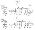
- FIGS. 1(A) and 1(B) are a top view ( FIG. 1(A) ) and a side view ( FIG. 1(B) ) illustrating an example of a principal configuration of a projection-type image display device of an embodiment of the present invention, and here a local right-handed rectangular coordinate system is introduced in the drawings. That is, in FIG. 1(A) , a longitudinal direction of a multiple reflection element (rod lens) is a Z axis, an axis parallel to a paper surface in a plane perpendicular to the Z axis is an X axis, and an axis running from the back to the front of the paper surface is a Y axis. Further, in FIG.
- FIG. 1(A) is a top view of the projection-type image display device as viewed from the Y axis direction
- FIG. 1(B) is a side view of the projection-type image display device as viewed from the X axis direction.
- a discharge lamp 1 and a reflector 2 configure a light source for radiating white light.
- the discharge lamp 1 an ultrahigh pressure mercury lamp can be used, for example. That is, the ultrahigh pressure mercury lamp can efficiently radiate the white light, and its luminance (intensity) is extremely high and its radiated light can be efficiently collected with a mirror surface that is the reflector 2 with an excellent light collecting property.
- the reflector 2 is configured from an ellipse rotation surface that is a rotated ellipse (note that, a semicircle) having a first focal point (short focal point) and a second focal point (long focal point), and has a dielectric multilayer film formed on its inner surface, the multilayer film transmitting an infrared ray and efficiently reflecting visible light.
- the reflector 2 reflects a visible light component toward the second focal point (long focal point), among the light radiated from the discharge lamp 1 arranged at the first focal point (short focal point).
- a multiple reflection element as a light-collecting optical element that is, a rod lens 3 is arranged at a rear part of the light source in the Z axis direction, and the light emitted from the discharge lamp 1 is captured/collected by the reflector 2, and enters the rod lens 3.
- an incoming surface (the left end part in the drawing) of the rod lens 3 is arranged at the second focal point (long focal point) of the ellipsoidal mirror 2, that is, in the vicinity of a position where the visible light component reflected at the reflector is collected.
- An emission surface of the rod lens 3 has a shape long in the X axis direction and short in the Y axis direction.
- a color wheel 4 is arranged in the vicinity of the emission surface of the rod lens 3, the color wheel 4 being a rotation-type color filter.
- the color wheel 4 is a rotation-controllable disk-shaped color filter configured from six types of fan-shaped transmission-type color filters arranged in a circumference (rotating) direction in order, the six types of color filters respectively transmitting only R (red), G (green), B (blue), C (cyan), Y (yellow), and W (white) light.
- the color wheel 4 can be realized with three types of color filters including R (red), G (green), and B (blue), in place of the above-described six types of color filters.
- the white light output from the light source is decomposed into the six colors (R (red), G (green), B (blue), C (cyan), Y (yellow), W (white)) in time series.
- the light emitted from the color wheel 4 is irradiated on the reflection-type image display element 10 through relay lenses 5 to 8 that configure an illumination optical element that collects the emission light, and then through a TIR prism 9.
- relay lenses 5 to 8 that configure the illumination optical element.
- These relay lenses serve to prevent divergence of light by collecting the light emitted from the rod lens 3 and transmitted the color wheel 4. Further, the relay lenses serve to expand the uniform light distribution on the emission surface of the color wheel 4, onto a surface of the reflection-type image display element 10. Further, the relay lenses also serve to make light approximately parallel. Then, the TIR prism 9 totally reflects the entering light, thereby to lead the light to the reflection-type image display element 10.
- the reflection-type image display element 10 is a two-dimensional optical modulation element that can control individual cells, and an image formed of these cells is expanded and projected on the screen or the like, through a projection lens 11.
- the reflection-type image display element 10 is synchronized with rotation of the color wheel 4 by a control device (configured from a microcomputer and a memory) denoted with the reference sign 100 in the drawing. Accordingly, the reflection-type image display element 10 displays an image based on an image signal, for each color light of the color wheel 4, and reflects the light entering from the TIR prism 9 toward a direction of the projection lens 11. That is, the light rays reflected at the reflection-type image display element 10 become to have an angle that does not satisfy a total reflection angle of the TIR prism 9, and thus are transmitted the TIR prism 9, and enter the projection lens 11.
- illumination optical system an optical system from where the light is transmitted the TIR prism 9 after emitted from the color wheel 4 to where the light reaches the surface of the reflection-type image display element 10 is referred to as illumination optical system.
- the inventors have attempted various examinations, that is, the inventors have found that, when the rod lens is formed of a group of four rods that are formed to divide the cross section of the rod lens into four equal parts, as exemplarily illustrated in PATENT LITERATURE 2, an adhesive applied on a joint surface, for joining these four rods, is subject to high temperature and deteriorated, and the deterioration is led to failure of the device and the like, and becomes a major cause to shorten the product life.
- the present invention has been made in view of the problem of when the rod lens is actually mounted in the projection-type image display device, and provides a mounting structure of the rod lens in the optical system with a large amount of heat generation.
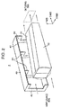
- FIG. 2 is a perspective view including a partial cross section of the rod lens 3 for illustrating the entire configuration of the rod lens 3, and as is clear from the drawing, the rod lens 3 has the incoming surface (the left side in the drawing) formed into a square so as to efficiently collect circular incoming light radiated from the normal light source, and has the outgoing surface formed into a rectangle so that the aspect ratio becomes the same as that of the reflection-type image display element 10 as the optical modulation element, as described above.
- the rod lens 3 is configured from two (only a pair of) rods 31 and 32 divided along an optical axis of the rod lens 3 to divide the rectangular cross section of the outgoing side of the rod lens 3 into two equal parts with long sides of the rod lens 3, that is, in a vertical direction.
- FIG. 3(A) illustrates a front view of an incoming side of the pair of rods 31 and 32 that configure the rod lens 3
- FIG. 3(B) illustrates a side view
- FIG. 3(C) illustrates a back view of the outgoing side of the pair of rods 31 and 32, respectively.
- the pair of rods 31 and 32 has mutually facing surfaces extending in an optical axis direction and held parallel to each other in a state of being slightly separated, with a thin film on a surface and a structure of a cover unit 40 described below. Accordingly, an extremely thin air layer is formed between the pair of rods 31 and 32, and the light propagated in the rods is reflected at an interface being a separation surface of these rods. Therefore, these rods 31 and 32 can be reliably separated.
- FIG. 4 illustrates a perspective view of a partially enlarged joint part of the pair of rods 31 and 32.
- the thickness of the thin film can be made small if the flatness of the joint surface of the rods 31 and 32 is high.
- the above-described cover unit 40 includes four external walls 41 provided to cover the pair of rods 31 and 32 (only two walls are illustrated in the drawing), a frame part 42 having an opening and arranged at a light source side (that is, at the incoming side), a frame part 43 having an opening and arranged at the outgoing side (that is, at a reflection-type image display element side), and a plurality of frame parts formed protruding from an inner surface of the external wall like a frame.
- the frame part 42 arranged at the incoming side serves as a diaphragm of the incoming light with a circular cross section from the light source side to the rod lens 3.
- tip parts of a plurality of frame parts 44 formed protruding from an inner surface of the external wall 41 are in contact with external peripheries of the pair of rods 31 and 32, and are formed tapered. That is, the plurality of holding frame parts 44 holds the pair of rods 31 and 32 at predetermined positions from the external peripheries by line con tact.
- FIGS. 4 and 5 illustrate positional relationship between the fronts of the pair of rods 31 and 32, and the frame part 42 arranged at the light source side (incoming side) of the cover unit 40. That is, as is clear from the drawings, when the rod lens 3 is viewed from an opening side of the cover unit 40 (illustrated by the broken line in the drawing) (that is, through the frame part 42 at the incoming side), the thin films 33 formed on the facing surface of the pair of rods 31 and 32 are hidden by the frame part 42 (that is, positioned outside the opening). According to this configuration, the extremely intense light radiated from the light source and collected with the reflector is not directly irradiated on the thin films 33 formed at positions close to the incoming surface.
- the cover unit 40 can be manufactured into the above-described shape by casting metal such as aluminum (Al) or magnesium (Mg).
- a rod lens suitable for mounting in an optical system irradiated with extremely intense light associated with a recent increase in the light emission intensity of a light source, and a configuration of a projection-type image display device in which the rod lens is mounted are provided.
- the present invention is not limited to the example, and can be applied to various projection-type image display devices, instead.
- a ferroelectric liquid crystal panel as a bistable element that switches two states of ON/OFF can be used.
- the TIR prism 9 that configures a part of the illumination optical system would become unnecessary.
- one configured from the plurality of transmission-type color filters has been described as the color wheel 4 being a rotation-type color filter.
- the present invention is not limited to the example, and reflection-type color filters can be used, instead.
- the present invention is not limited to the above-described embodiments, and includes various modifications.
- detailed description has been given in the embodiments in order to explain the present invention in ways easy to understand, and the present invention is not necessarily limited to one that includes all of the described configurations.
- a part of a configuration of a certain embodiment can be replaced with a configuration of another embodiment, and a configuration of a certain embodiment can be added to a configuration of another embodiment.
- another configuration can be added to/deleted from/replaced with a part of a configuration of each embodiment.
Landscapes
- Physics & Mathematics (AREA)
- General Physics & Mathematics (AREA)
- Optics & Photonics (AREA)
- Chemical & Material Sciences (AREA)
- Crystallography & Structural Chemistry (AREA)
- Nonlinear Science (AREA)
- Multimedia (AREA)
- Signal Processing (AREA)
- Engineering & Computer Science (AREA)
- Mathematical Physics (AREA)
- Projection Apparatus (AREA)
- Non-Portable Lighting Devices Or Systems Thereof (AREA)
- Planar Illumination Modules (AREA)
- Transforming Electric Information Into Light Information (AREA)
Applications Claiming Priority (1)
| Application Number | Priority Date | Filing Date | Title |
|---|---|---|---|
| PCT/JP2013/059549 WO2014155675A1 (ja) | 2013-03-29 | 2013-03-29 | 投写型映像表示装置 |
Publications (4)
| Publication Number | Publication Date |
|---|---|
| EP2985656A1 true EP2985656A1 (de) | 2016-02-17 |
| EP2985656A4 EP2985656A4 (de) | 2016-09-21 |
| EP2985656B1 EP2985656B1 (de) | 2018-02-14 |
| EP2985656B8 EP2985656B8 (de) | 2018-03-21 |
Family
ID=51622736
Family Applications (1)
| Application Number | Title | Priority Date | Filing Date |
|---|---|---|---|
| EP13879972.1A Active EP2985656B8 (de) | 2013-03-29 | 2013-03-29 | Projektionsbild-anzeigevorrichtung |
Country Status (5)
| Country | Link |
|---|---|
| US (1) | US9519205B2 (de) |
| EP (1) | EP2985656B8 (de) |
| JP (1) | JP6012850B2 (de) |
| CN (1) | CN104885008B (de) |
| WO (1) | WO2014155675A1 (de) |
Families Citing this family (5)
| Publication number | Priority date | Publication date | Assignee | Title |
|---|---|---|---|---|
| KR20150094403A (ko) * | 2014-02-11 | 2015-08-19 | 삼성전자주식회사 | 조명용 로드 렌즈 및 조명용 로드 렌즈를 포함하는 조명 장치 |
| US10237524B2 (en) * | 2016-08-05 | 2019-03-19 | Panasonic Intellectual Property Management Co., Ltd. | Lighting device and projection display apparatus using the same |
| US11988375B2 (en) | 2019-11-14 | 2024-05-21 | Nichia Corporation | Light source unit, light source module, and lighting device |
| JP2021096978A (ja) * | 2019-12-18 | 2021-06-24 | ミネベアミツミ株式会社 | 面状照明装置 |
| JP7330651B2 (ja) * | 2021-01-19 | 2023-08-22 | 株式会社セガトイズ | 映像表示装置 |
Family Cites Families (18)
| Publication number | Priority date | Publication date | Assignee | Title |
|---|---|---|---|---|
| JPH09222603A (ja) | 1996-02-15 | 1997-08-26 | Casio Comput Co Ltd | 液晶表示装置 |
| JP3610789B2 (ja) | 1998-10-28 | 2005-01-19 | セイコーエプソン株式会社 | 照明装置およびそれを用いた投写型表示装置 |
| JP3610835B2 (ja) * | 1999-08-17 | 2005-01-19 | セイコーエプソン株式会社 | 照明装置およびそれを用いた投写型表示装置 |
| JP2003043411A (ja) * | 2001-08-03 | 2003-02-13 | Kyocera Corp | 照明光学系 |
| US6773218B1 (en) * | 2003-02-10 | 2004-08-10 | Harry Mingoes | Adjustable ceiling panel lifting apparatus |
| JP2005024963A (ja) * | 2003-07-03 | 2005-01-27 | Seiko Epson Corp | 照明装置および投写型表示装置 |
| TWM246605U (en) * | 2003-11-24 | 2004-10-11 | Benq Corp | Light pipe bracket |
| JP2005249363A (ja) | 2004-03-08 | 2005-09-15 | Daikin Ind Ltd | 酸素富化給気ユニットおよび空気調和機の室外機 |
| JP4102807B2 (ja) | 2005-01-31 | 2008-06-18 | Necディスプレイソリューションズ株式会社 | 表示パネルの照明光学系、およびその照明光学系を有するプロジェクタ |
| JP2007101711A (ja) * | 2005-09-30 | 2007-04-19 | Sanyo Electric Co Ltd | ロッドインテグレータ及び照明装置及び投写型映像表示装置 |
| TWI286226B (en) * | 2006-01-03 | 2007-09-01 | Coretronic Corp | Light source module and optical projection apparatus |
| JP2007256337A (ja) * | 2006-03-20 | 2007-10-04 | Funai Electric Co Ltd | プロジェクタ |
| CN101454719B (zh) | 2006-05-29 | 2010-06-23 | 松下电器产业株式会社 | 投射型显示装置 |
| JP5045993B2 (ja) * | 2006-12-12 | 2012-10-10 | カシオ計算機株式会社 | 導光ユニット及びプロジェクタ |
| JP2008209811A (ja) * | 2007-02-28 | 2008-09-11 | Hitachi Ltd | 表示装置及び投写型照明装置 |
| TW200944924A (en) * | 2008-04-18 | 2009-11-01 | Coretronic Corp | Projector and module of integration rod |
| CN102239445A (zh) * | 2008-12-05 | 2011-11-09 | 三洋电机株式会社 | 照明装置及投射型影像显示装置 |
| JP5765000B2 (ja) * | 2011-03-25 | 2015-08-19 | セイコーエプソン株式会社 | 液晶装置及びプロジェクター |
-
2013
- 2013-03-29 EP EP13879972.1A patent/EP2985656B8/de active Active
- 2013-03-29 JP JP2015507874A patent/JP6012850B2/ja active Active
- 2013-03-29 CN CN201380067740.0A patent/CN104885008B/zh active Active
- 2013-03-29 US US14/654,852 patent/US9519205B2/en active Active
- 2013-03-29 WO PCT/JP2013/059549 patent/WO2014155675A1/ja not_active Ceased
Also Published As
| Publication number | Publication date |
|---|---|
| JPWO2014155675A1 (ja) | 2017-02-16 |
| CN104885008A (zh) | 2015-09-02 |
| WO2014155675A1 (ja) | 2014-10-02 |
| CN104885008B (zh) | 2016-06-29 |
| EP2985656A4 (de) | 2016-09-21 |
| US20160085142A1 (en) | 2016-03-24 |
| US9519205B2 (en) | 2016-12-13 |
| EP2985656B8 (de) | 2018-03-21 |
| JP6012850B2 (ja) | 2016-10-25 |
| EP2985656B1 (de) | 2018-02-14 |
Similar Documents
| Publication | Publication Date | Title |
|---|---|---|
| CN101398599B (zh) | 投影机的光学装置及投影机 | |
| CN108663879B (zh) | 投影机及其照明系统 | |
| US20160088273A1 (en) | Light source device and projection type image display device | |
| US9519205B2 (en) | Projection image display device | |
| KR20040111059A (ko) | 광원 장치 및 프로젝터 | |
| US20150323156A1 (en) | Light source device | |
| CN106814528B (zh) | 投影装置及其照明系统 | |
| CN110554554B (zh) | 照明系统以及投影装置 | |
| KR20030083872A (ko) | 컬러드럼을 이용한 투사장치 | |
| JPWO2015111145A1 (ja) | 光源装置およびこれを用いた映像表示装置 | |
| JPH09325313A (ja) | 投射型液晶表示装置 | |
| JP4961167B2 (ja) | 照明装置及び投写型映像表示装置 | |
| TW200540363A (en) | Light source device, illumination optical device, and display device | |
| US20190310411A1 (en) | Optical system with diffusers and honeycomb condensers | |
| US20090066920A1 (en) | Projection type image display device | |
| US7611249B2 (en) | Projector | |
| CN101021676A (zh) | 投影机 | |
| JP3893872B2 (ja) | 偏光変換素子およびプロジェクタ | |
| CN100437345C (zh) | 照明系统 | |
| JPH11352444A (ja) | 映像表示装置 | |
| JP2005024664A (ja) | 偏光照明光学系およびこれを用いた投写型表示装置 | |
| JP4696519B2 (ja) | 光学変調装置およびプロジェクタ | |
| CN118466096A (zh) | 投影装置 | |
| JP2004363019A (ja) | 光源ランプおよびこれを備えたプロジェクタ | |
| KR20070120789A (ko) | 프로젝션 장치 |
Legal Events
| Date | Code | Title | Description |
|---|---|---|---|
| PUAI | Public reference made under article 153(3) epc to a published international application that has entered the european phase |
Free format text: ORIGINAL CODE: 0009012 |
|
| 17P | Request for examination filed |
Effective date: 20150623 |
|
| AK | Designated contracting states |
Kind code of ref document: A1 Designated state(s): AL AT BE BG CH CY CZ DE DK EE ES FI FR GB GR HR HU IE IS IT LI LT LU LV MC MK MT NL NO PL PT RO RS SE SI SK SM TR |
|
| AX | Request for extension of the european patent |
Extension state: BA ME |
|
| DAX | Request for extension of the european patent (deleted) | ||
| A4 | Supplementary search report drawn up and despatched |
Effective date: 20160824 |
|
| RIC1 | Information provided on ipc code assigned before grant |
Ipc: H04N 5/74 20060101ALI20160818BHEP Ipc: G02F 1/1335 20060101ALI20160818BHEP Ipc: F21V 8/00 20060101ALI20160818BHEP Ipc: G02B 13/16 20060101ALI20160818BHEP Ipc: G02B 7/02 20060101ALI20160818BHEP Ipc: G03B 21/00 20060101AFI20160818BHEP Ipc: G03B 21/20 20060101ALI20160818BHEP Ipc: G02B 13/00 20060101ALI20160818BHEP |
|
| GRAP | Despatch of communication of intention to grant a patent |
Free format text: ORIGINAL CODE: EPIDOSNIGR1 |
|
| RIC1 | Information provided on ipc code assigned before grant |
Ipc: H04N 5/74 20060101ALI20170811BHEP Ipc: G02B 13/16 20060101ALI20170811BHEP Ipc: G02B 7/02 20060101ALI20170811BHEP Ipc: G03B 21/20 20060101ALI20170811BHEP Ipc: G02B 13/00 20060101ALI20170811BHEP Ipc: G02F 1/1335 20060101ALI20170811BHEP Ipc: G03B 21/00 20060101AFI20170811BHEP Ipc: F21V 8/00 20060101ALI20170811BHEP |
|
| INTG | Intention to grant announced |
Effective date: 20170907 |
|
| GRAS | Grant fee paid |
Free format text: ORIGINAL CODE: EPIDOSNIGR3 |
|
| GRAA | (expected) grant |
Free format text: ORIGINAL CODE: 0009210 |
|
| GRAT | Correction requested after decision to grant or after decision to maintain patent in amended form |
Free format text: ORIGINAL CODE: EPIDOSNCDEC |
|
| AK | Designated contracting states |
Kind code of ref document: B1 Designated state(s): AL AT BE BG CH CY CZ DE DK EE ES FI FR GB GR HR HU IE IS IT LI LT LU LV MC MK MT NL NO PL PT RO RS SE SI SK SM TR |
|
| REG | Reference to a national code |
Ref country code: GB Ref legal event code: FG4D |
|
| REG | Reference to a national code |
Ref country code: CH Ref legal event code: EP |
|
| RAP2 | Party data changed (patent owner data changed or rights of a patent transferred) |
Owner name: MAXELL, LTD. |
|
| REG | Reference to a national code |
Ref country code: IE Ref legal event code: FG4D |
|
| REG | Reference to a national code |
Ref country code: DE Ref legal event code: R096 Ref document number: 602013033214 Country of ref document: DE Ref country code: AT Ref legal event code: REF Ref document number: 970244 Country of ref document: AT Kind code of ref document: T Effective date: 20180315 |
|
| REG | Reference to a national code |
Ref country code: FR Ref legal event code: PLFP Year of fee payment: 6 |
|
| REG | Reference to a national code |
Ref country code: DE Ref legal event code: R081 Ref document number: 602013033214 Country of ref document: DE Owner name: MAXELL, LTD., OYAMAZAKI, JP Free format text: FORMER OWNER: HITACHI MAXELL, LTD., IBARAKI-SHI, OSAKA, JP |
|
| REG | Reference to a national code |
Ref country code: NL Ref legal event code: MP Effective date: 20180214 |
|
| REG | Reference to a national code |
Ref country code: AT Ref legal event code: MK05 Ref document number: 970244 Country of ref document: AT Kind code of ref document: T Effective date: 20180214 |
|
| PG25 | Lapsed in a contracting state [announced via postgrant information from national office to epo] |
Ref country code: NL Free format text: LAPSE BECAUSE OF FAILURE TO SUBMIT A TRANSLATION OF THE DESCRIPTION OR TO PAY THE FEE WITHIN THE PRESCRIBED TIME-LIMIT Effective date: 20180214 Ref country code: CY Free format text: LAPSE BECAUSE OF FAILURE TO SUBMIT A TRANSLATION OF THE DESCRIPTION OR TO PAY THE FEE WITHIN THE PRESCRIBED TIME-LIMIT Effective date: 20180214 Ref country code: FI Free format text: LAPSE BECAUSE OF FAILURE TO SUBMIT A TRANSLATION OF THE DESCRIPTION OR TO PAY THE FEE WITHIN THE PRESCRIBED TIME-LIMIT Effective date: 20180214 Ref country code: NO Free format text: LAPSE BECAUSE OF FAILURE TO SUBMIT A TRANSLATION OF THE DESCRIPTION OR TO PAY THE FEE WITHIN THE PRESCRIBED TIME-LIMIT Effective date: 20180514 Ref country code: LT Free format text: LAPSE BECAUSE OF FAILURE TO SUBMIT A TRANSLATION OF THE DESCRIPTION OR TO PAY THE FEE WITHIN THE PRESCRIBED TIME-LIMIT Effective date: 20180214 Ref country code: HR Free format text: LAPSE BECAUSE OF FAILURE TO SUBMIT A TRANSLATION OF THE DESCRIPTION OR TO PAY THE FEE WITHIN THE PRESCRIBED TIME-LIMIT Effective date: 20180214 Ref country code: ES Free format text: LAPSE BECAUSE OF FAILURE TO SUBMIT A TRANSLATION OF THE DESCRIPTION OR TO PAY THE FEE WITHIN THE PRESCRIBED TIME-LIMIT Effective date: 20180214 |
|
| PG25 | Lapsed in a contracting state [announced via postgrant information from national office to epo] |
Ref country code: SE Free format text: LAPSE BECAUSE OF FAILURE TO SUBMIT A TRANSLATION OF THE DESCRIPTION OR TO PAY THE FEE WITHIN THE PRESCRIBED TIME-LIMIT Effective date: 20180214 Ref country code: LV Free format text: LAPSE BECAUSE OF FAILURE TO SUBMIT A TRANSLATION OF THE DESCRIPTION OR TO PAY THE FEE WITHIN THE PRESCRIBED TIME-LIMIT Effective date: 20180214 Ref country code: AT Free format text: LAPSE BECAUSE OF FAILURE TO SUBMIT A TRANSLATION OF THE DESCRIPTION OR TO PAY THE FEE WITHIN THE PRESCRIBED TIME-LIMIT Effective date: 20180214 Ref country code: RS Free format text: LAPSE BECAUSE OF FAILURE TO SUBMIT A TRANSLATION OF THE DESCRIPTION OR TO PAY THE FEE WITHIN THE PRESCRIBED TIME-LIMIT Effective date: 20180214 Ref country code: BG Free format text: LAPSE BECAUSE OF FAILURE TO SUBMIT A TRANSLATION OF THE DESCRIPTION OR TO PAY THE FEE WITHIN THE PRESCRIBED TIME-LIMIT Effective date: 20180514 Ref country code: GR Free format text: LAPSE BECAUSE OF FAILURE TO SUBMIT A TRANSLATION OF THE DESCRIPTION OR TO PAY THE FEE WITHIN THE PRESCRIBED TIME-LIMIT Effective date: 20180515 |
|
| PG25 | Lapsed in a contracting state [announced via postgrant information from national office to epo] |
Ref country code: IT Free format text: LAPSE BECAUSE OF FAILURE TO SUBMIT A TRANSLATION OF THE DESCRIPTION OR TO PAY THE FEE WITHIN THE PRESCRIBED TIME-LIMIT Effective date: 20180214 Ref country code: RO Free format text: LAPSE BECAUSE OF FAILURE TO SUBMIT A TRANSLATION OF THE DESCRIPTION OR TO PAY THE FEE WITHIN THE PRESCRIBED TIME-LIMIT Effective date: 20180214 Ref country code: PL Free format text: LAPSE BECAUSE OF FAILURE TO SUBMIT A TRANSLATION OF THE DESCRIPTION OR TO PAY THE FEE WITHIN THE PRESCRIBED TIME-LIMIT Effective date: 20180214 Ref country code: EE Free format text: LAPSE BECAUSE OF FAILURE TO SUBMIT A TRANSLATION OF THE DESCRIPTION OR TO PAY THE FEE WITHIN THE PRESCRIBED TIME-LIMIT Effective date: 20180214 Ref country code: AL Free format text: LAPSE BECAUSE OF FAILURE TO SUBMIT A TRANSLATION OF THE DESCRIPTION OR TO PAY THE FEE WITHIN THE PRESCRIBED TIME-LIMIT Effective date: 20180214 |
|
| REG | Reference to a national code |
Ref country code: CH Ref legal event code: PL |
|
| REG | Reference to a national code |
Ref country code: DE Ref legal event code: R097 Ref document number: 602013033214 Country of ref document: DE |
|
| PG25 | Lapsed in a contracting state [announced via postgrant information from national office to epo] |
Ref country code: DK Free format text: LAPSE BECAUSE OF FAILURE TO SUBMIT A TRANSLATION OF THE DESCRIPTION OR TO PAY THE FEE WITHIN THE PRESCRIBED TIME-LIMIT Effective date: 20180214 Ref country code: SM Free format text: LAPSE BECAUSE OF FAILURE TO SUBMIT A TRANSLATION OF THE DESCRIPTION OR TO PAY THE FEE WITHIN THE PRESCRIBED TIME-LIMIT Effective date: 20180214 Ref country code: SK Free format text: LAPSE BECAUSE OF FAILURE TO SUBMIT A TRANSLATION OF THE DESCRIPTION OR TO PAY THE FEE WITHIN THE PRESCRIBED TIME-LIMIT Effective date: 20180214 Ref country code: MC Free format text: LAPSE BECAUSE OF FAILURE TO SUBMIT A TRANSLATION OF THE DESCRIPTION OR TO PAY THE FEE WITHIN THE PRESCRIBED TIME-LIMIT Effective date: 20180214 Ref country code: CZ Free format text: LAPSE BECAUSE OF FAILURE TO SUBMIT A TRANSLATION OF THE DESCRIPTION OR TO PAY THE FEE WITHIN THE PRESCRIBED TIME-LIMIT Effective date: 20180214 |
|
| REG | Reference to a national code |
Ref country code: BE Ref legal event code: MM Effective date: 20180331 |
|
| PLBE | No opposition filed within time limit |
Free format text: ORIGINAL CODE: 0009261 |
|
| STAA | Information on the status of an ep patent application or granted ep patent |
Free format text: STATUS: NO OPPOSITION FILED WITHIN TIME LIMIT |
|
| REG | Reference to a national code |
Ref country code: IE Ref legal event code: MM4A |
|
| PG25 | Lapsed in a contracting state [announced via postgrant information from national office to epo] |
Ref country code: LU Free format text: LAPSE BECAUSE OF NON-PAYMENT OF DUE FEES Effective date: 20180329 |
|
| 26N | No opposition filed |
Effective date: 20181115 |
|
| PG25 | Lapsed in a contracting state [announced via postgrant information from national office to epo] |
Ref country code: IE Free format text: LAPSE BECAUSE OF NON-PAYMENT OF DUE FEES Effective date: 20180329 |
|
| PG25 | Lapsed in a contracting state [announced via postgrant information from national office to epo] |
Ref country code: BE Free format text: LAPSE BECAUSE OF NON-PAYMENT OF DUE FEES Effective date: 20180331 Ref country code: CH Free format text: LAPSE BECAUSE OF NON-PAYMENT OF DUE FEES Effective date: 20180331 Ref country code: SI Free format text: LAPSE BECAUSE OF FAILURE TO SUBMIT A TRANSLATION OF THE DESCRIPTION OR TO PAY THE FEE WITHIN THE PRESCRIBED TIME-LIMIT Effective date: 20180214 Ref country code: LI Free format text: LAPSE BECAUSE OF NON-PAYMENT OF DUE FEES Effective date: 20180331 |
|
| PG25 | Lapsed in a contracting state [announced via postgrant information from national office to epo] |
Ref country code: MT Free format text: LAPSE BECAUSE OF NON-PAYMENT OF DUE FEES Effective date: 20180329 |
|
| PG25 | Lapsed in a contracting state [announced via postgrant information from national office to epo] |
Ref country code: TR Free format text: LAPSE BECAUSE OF FAILURE TO SUBMIT A TRANSLATION OF THE DESCRIPTION OR TO PAY THE FEE WITHIN THE PRESCRIBED TIME-LIMIT Effective date: 20180214 |
|
| PG25 | Lapsed in a contracting state [announced via postgrant information from national office to epo] |
Ref country code: PT Free format text: LAPSE BECAUSE OF FAILURE TO SUBMIT A TRANSLATION OF THE DESCRIPTION OR TO PAY THE FEE WITHIN THE PRESCRIBED TIME-LIMIT Effective date: 20180214 |
|
| PG25 | Lapsed in a contracting state [announced via postgrant information from national office to epo] |
Ref country code: MK Free format text: LAPSE BECAUSE OF NON-PAYMENT OF DUE FEES Effective date: 20180214 Ref country code: HU Free format text: LAPSE BECAUSE OF FAILURE TO SUBMIT A TRANSLATION OF THE DESCRIPTION OR TO PAY THE FEE WITHIN THE PRESCRIBED TIME-LIMIT; INVALID AB INITIO Effective date: 20130329 |
|
| PG25 | Lapsed in a contracting state [announced via postgrant information from national office to epo] |
Ref country code: IS Free format text: LAPSE BECAUSE OF FAILURE TO SUBMIT A TRANSLATION OF THE DESCRIPTION OR TO PAY THE FEE WITHIN THE PRESCRIBED TIME-LIMIT Effective date: 20180614 |
|
| REG | Reference to a national code |
Ref country code: GB Ref legal event code: 732E Free format text: REGISTERED BETWEEN 20220728 AND 20220803 |
|
| REG | Reference to a national code |
Ref country code: DE Ref legal event code: R081 Ref document number: 602013033214 Country of ref document: DE Owner name: MAXELL, LTD., OYAMAZAKI, JP Free format text: FORMER OWNER: MAXELL, LTD., OYAMAZAKI, KYOTO, JP |
|
| REG | Reference to a national code |
Ref country code: DE Ref legal event code: R081 Ref document number: 602013033214 Country of ref document: DE Owner name: MAXELL, LTD., OYAMAZAKI, JP Free format text: FORMER OWNER: MAXELL HOLDINGS, LTD., OYAMAZAKI, KYOTO, JP |
|
| PGFP | Annual fee paid to national office [announced via postgrant information from national office to epo] |
Ref country code: GB Payment date: 20260324 Year of fee payment: 14 |
|
| PGFP | Annual fee paid to national office [announced via postgrant information from national office to epo] |
Ref country code: DE Payment date: 20260319 Year of fee payment: 14 |
|
| PGFP | Annual fee paid to national office [announced via postgrant information from national office to epo] |
Ref country code: FR Payment date: 20260320 Year of fee payment: 14 |