EP2985668B1 - Soupape et robinet thermostatiques à double commande à manche unique - Google Patents
Soupape et robinet thermostatiques à double commande à manche unique Download PDFInfo
- Publication number
- EP2985668B1 EP2985668B1 EP15155716.2A EP15155716A EP2985668B1 EP 2985668 B1 EP2985668 B1 EP 2985668B1 EP 15155716 A EP15155716 A EP 15155716A EP 2985668 B1 EP2985668 B1 EP 2985668B1
- Authority
- EP
- European Patent Office
- Prior art keywords
- water
- hot water
- channel
- valve
- cold water
- Prior art date
- Legal status (The legal status is an assumption and is not a legal conclusion. Google has not performed a legal analysis and makes no representation as to the accuracy of the status listed.)
- Not-in-force
Links
- XLYOFNOQVPJJNP-UHFFFAOYSA-N water Substances O XLYOFNOQVPJJNP-UHFFFAOYSA-N 0.000 claims description 595
- 239000000919 ceramic Substances 0.000 claims description 101
- 230000001105 regulatory effect Effects 0.000 claims description 61
- 230000003068 static effect Effects 0.000 claims description 45
- 238000007789 sealing Methods 0.000 claims description 41
- 230000001276 controlling effect Effects 0.000 claims description 37
- 229920001971 elastomer Polymers 0.000 claims description 20
- 239000000806 elastomer Substances 0.000 claims description 20
- 230000009471 action Effects 0.000 claims description 16
- 230000008859 change Effects 0.000 claims description 13
- 230000002093 peripheral effect Effects 0.000 claims description 9
- 238000006073 displacement reaction Methods 0.000 claims description 8
- 238000002955 isolation Methods 0.000 claims description 4
- 230000033228 biological regulation Effects 0.000 description 5
- 238000009434 installation Methods 0.000 description 5
- 238000009966 trimming Methods 0.000 description 3
- 230000003139 buffering effect Effects 0.000 description 2
- 230000009467 reduction Effects 0.000 description 2
- 230000008901 benefit Effects 0.000 description 1
- 230000008602 contraction Effects 0.000 description 1
- 230000003247 decreasing effect Effects 0.000 description 1
- 210000004907 gland Anatomy 0.000 description 1
- 230000001788 irregular Effects 0.000 description 1
- 238000005461 lubrication Methods 0.000 description 1
- 230000007246 mechanism Effects 0.000 description 1
- 238000000034 method Methods 0.000 description 1
- 230000008569 process Effects 0.000 description 1
- 230000000750 progressive effect Effects 0.000 description 1
Images







Classifications
-
- G—PHYSICS
- G05—CONTROLLING; REGULATING
- G05D—SYSTEMS FOR CONTROLLING OR REGULATING NON-ELECTRIC VARIABLES
- G05D23/00—Control of temperature
- G05D23/01—Control of temperature without auxiliary power
- G05D23/13—Control of temperature without auxiliary power by varying the mixing ratio of two fluids having different temperatures
- G05D23/1306—Control of temperature without auxiliary power by varying the mixing ratio of two fluids having different temperatures for liquids
- G05D23/132—Control of temperature without auxiliary power by varying the mixing ratio of two fluids having different temperatures for liquids with temperature sensing element
- G05D23/134—Control of temperature without auxiliary power by varying the mixing ratio of two fluids having different temperatures for liquids with temperature sensing element measuring the temperature of mixed fluid
- G05D23/1346—Control of temperature without auxiliary power by varying the mixing ratio of two fluids having different temperatures for liquids with temperature sensing element measuring the temperature of mixed fluid with manual temperature setting means
- G05D23/1353—Control of temperature without auxiliary power by varying the mixing ratio of two fluids having different temperatures for liquids with temperature sensing element measuring the temperature of mixed fluid with manual temperature setting means combined with flow controlling means
-
- F—MECHANICAL ENGINEERING; LIGHTING; HEATING; WEAPONS; BLASTING
- F16—ENGINEERING ELEMENTS AND UNITS; GENERAL MEASURES FOR PRODUCING AND MAINTAINING EFFECTIVE FUNCTIONING OF MACHINES OR INSTALLATIONS; THERMAL INSULATION IN GENERAL
- F16K—VALVES; TAPS; COCKS; ACTUATING-FLOATS; DEVICES FOR VENTING OR AERATING
- F16K11/00—Multiple-way valves, e.g. mixing valves; Pipe fittings incorporating such valves
- F16K11/02—Multiple-way valves, e.g. mixing valves; Pipe fittings incorporating such valves with all movable sealing faces moving as one unit
- F16K11/06—Multiple-way valves, e.g. mixing valves; Pipe fittings incorporating such valves with all movable sealing faces moving as one unit comprising only sliding valves, i.e. sliding closure elements
- F16K11/078—Multiple-way valves, e.g. mixing valves; Pipe fittings incorporating such valves with all movable sealing faces moving as one unit comprising only sliding valves, i.e. sliding closure elements with pivoted and linearly movable closure members
- F16K11/0782—Single-lever operated mixing valves with closure members having flat sealing faces
- F16K11/0787—Single-lever operated mixing valves with closure members having flat sealing faces with both the supply and the discharge passages being on the same side of the closure members
Definitions
- the present invention relates to a single-handle dual-control thermostatic valve and faucet.
- the thermostatic faucet is popular among the consumers due to its convenience in water temperature regulation and has been widely applied in various types of bathwater supply systems of various occasions. Constant temperature mainly means that a user can self-regulate the water outlet temperature according to his/her needs and the mixed water from outlet can keep a constant temperature upon setting.
- the advantage of the thermostatic faucet is that, it is safe and burn-proof, the tremendous change in the outgoing water temperature can be avoided, which is caused by the change in water incoming pressure or the instable water incoming temperature occurred in the ordinary valve core.
- thermostatic valve's function and structure determine directly those of the thermostatic faucet and further the user's experience, including the convenience in use and completeness in function.
- the thermostatic faucet available now, by operating its single handle, only the water outgoing temperature can be set and the water outlet's switching on/off can be controlled, and the water outgoing flow cannot be regulated freely and the user's higher expectation in use cannot be met accordingly.
- the present invention is designed to provide a single-handle dual-control thermostatic valve with optimized structure of the valve core body and increased flow in the valve body and a single-handle dual-control thermostatic faucet in which the thermostatic valve is provided.
- Each of US-A-2011/240155 , US-A-2003/234925 and CN-A-201034188 discloses a single-handle dual-control thermostatic valve.
- a single-handle dual-control thermostatic valve comprises
- the temperature regulating part comprises a temperature regulating valve stem, a temperature regulating valve stem seat, a thermo-sensitive element, a regulator and a return spring, wherein a hole for the temperature regulating valve stem is provided at the top of the valve core body and the temperature regulating valve stem seat is fixed to the internal wall of the temperature regulating valve stem hole, the temperature regulating valve stem thread-fits with the temperature regulating valve stem seat and its upper end extends upwards;
- the regulator including a water control portion and a supporting portion is provided between the temperature regulating stem seat and the valve seat ,and the external peripheral wall of the water control portion is against the internal wall of the valve core body and the supporting portion is against the bottom of the temperature-regulating valve stem seat, the upper end and lower end of the water control portion are located at the hot water inlet and the cold water inlet of the valve core body respectively; a cold/hot isolation seal ring between the hot water inlet and the cold water inlet is provided on the external peripheral wall of the water control portion, the upper end of the thermo-sensitive element is
- control part comprises a driving lever, a driving lever seat, a drive plate and the drive plate's driver
- the driving lever seat and the drive plate are accommodated on the upper part of the internal cavity in the valve jacket
- the drive plate is located below the driving lever seat and connected with the dynamic ceramic chip
- the outer teeth at the upper end of the temperature regulating valve stem fits with the inner teeth in the center hole of the driving lever seat
- the lower part of the driving lever penetrates through the driving lever seat and is connected with the lever seat by a dowel
- the lower end of the driving lever is embedded into and fixed to the driving lever driver on the drive plate.
- the hot water inlet passage of the static ceramic chip is located outside of the hot water outlet passage and is longer than the latter; the cold water inlet passage is located outside of the cold water outlet passage and is longer than the latter.
- the water incoming end face of the hot water incoming channel and that of the cold water incoming channel are located on the bottom surface of the valve core body and are arc - shaped, the water outgoing end face of the hot water incoming channel, that of the cold water incoming channel, the water incoming end face of the hot water outgoing channel and that of the cold water outgoing channel are located on the top surface of the valve core body and are sector-shaped; and the water outgoing end face of the hot water incoming channel, that of the cold water incoming channel, the water incoming end face of the hot water outgoing channel and that of the cold water outgoing channel are identical in shape and size and evenly distributed along the circumference with a certain interval.
- thermo-sensitive element is connected with the regulator to drive the latter move
- a seal ring is provided between the upper end face of the water control portion of the regulator and the internal wall of the valve core body and between the lower end face of the water control portion and the upper end face of the valve seat, when the upper end face of the water control portion contacts with the internal wall of the valve core body, the seal ring closes the gap between the upper end face of the water control portion and the internal wall of the valve core body; when the lower end face of the water control portion contacts with the upper end face of the valve seat, the seal ring closes the gap between the lower end face of the water control portion and the upper end face of the valve seat.
- the seal ring is disposed on the upper end face and the lower end face of the water control portion.
- the present invention provides a single-handle dual-control faucet provided with a single-handle dual-control thermostatic valve as hereinbefore defined comprising a faucet shell, a thermostatic valve provided in the faucet shell, a handle which controls the thermostatic valve, a cold water incoming pipe, a hot water incoming pipe and a mixed water outgoing pipe which are connected with the faucet shell, the handle is connected with the driving lever of the thermostatic valve.
- the cold water incoming pipe and the hot water incoming pipe form an internal control cavity respectively, inside the control cavity, the following are provided: a hollow guiding part which is connected with the water inlet of the control cavity; a piston part provided between the guiding part and the water outgoing end of the control cavity; the internal cavity of the piston part is connected with the internal cavity of the guiding part, and the piston part having a water drawing portion, an elastomer action portion and the contact portion which are connected with one another successively can move axially inside the control cavity, wherein the water drawing portion is embedded into and connected with the guiding part, the contact portion is against the water outlet of the control cavity and a seal ring is provided between the outer edge of the elastomer action portion and the internal wall of the control cavity, a displacement elastomer provided between the elastomer action portion and the guiding part; a sealing pad provided on its installing portion can change the water route between the guiding part and the piston part.
- the sealing pad installing portion is a support for the sealing pad provided in the connecting portion of the water incoming pipe
- the sealing pad support comprises a water discharge portion having water discharge holes on its peripheral wall connected with the water inlet of the control cavity and a supporting portion provided on the water discharge portion, and the sealing pad is provided on the end face of the supporting portion; and the water drawing portion extends into the internal cavity of the guiding part, and the sealing pad is located at the water incoming side of the water drawing portion.
- the upper end of the guiding part extends into the water drawing portion of the piston part, the installing portion for the sealing pad is provided inside the contact portion, and the sealing pad is provided on the bottom surface of the installing portion of the sealing pad and is located at the water outgoing side of the guiding part.
- a hot water incoming channel, a cold water incoming channel, a hot water outgoing channel and a cold water outgoing channel are provided on the valve core body, that is, a quartered-water route structure is adopted in the present invention, so that the water discharge area of incoming water and outgoing water can be increased, and the flow of the valve core can also be increased accordingly.
- a hot water inlet passage, a hot water outlet passage, a cold water inlet passage and a cold water outlet passage are provided respectively
- a hot water controlling channel and a cold water controlling channel are provided for opening or shutting off both the water incoming channel and the water outgoing channel.
- the hot water and the cold water flow into the regulator through the ceramic chip and the water outgoing channel of the valve core body and are mixed in the water mixing zone, then the mixed water flows out of the mixed water outlet in the seat.
- the dynamic ceramic chip in the present invention does not change the flow of hot water and cold water into the regulator when it is rotating, and temperature is regulated by the regulator, which is driven by the thermostatic valve stem (driven by the driving lever seat).
- the different sliding positions of the dynamic ceramic chip can shut off or open the hot incoming water and the cold incoming water, while flow can be regulated at different positions to which the dynamic ceramic chip slides.
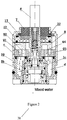
- the single-handle dual-control thermostatic valve in this embodiment comprises a thermostatic valve core, a valve jacket, a flow part and a control part, wherein the thermostatic valve core comprises a valve core body 1, a valve seat 3 and a temperature regulating part.
- the valve jacket 2 fits hermetically by a seal ring with the upper part of the valve core body 1, the valve seat 3 is provided inside the bottom of the valve core body 1, and both the valve core body 1 and the valve seat 3 form an area for accommodating the temperature regulating part and a water mixing zone.
- the temperature regulating part comprises a temperature regulating valve stem 4, a temperature regulating valve stem seat 5,a thermo-sensitive element 10, a regulator 11 and a return spring 14.
- the temperature regulating part further includes a trim lever 15, an ejector pin 16, a locking spring 17, a buffering spring 18, a cold/hot water isolation seal ring 19 and a top cap 20.
- a regulating valve stem hole 1a is drilled on the top of the valve core body 1.
- the temperature regulating valve stem seat 5 is fixed to the internal wall of the temperature regulating valve stem hole 1a, and the temperature regulating valve stem 4 thread-fits with the temperature regulating valve stem seat 5 and its upper end extends upwards.
- a hot water incoming channel a , a cold water incoming channel b, a hot water outgoing channel c and a cold water outgoing channel d are provided on the valve core body 1 respectively.
- an axial hole is drilled inside the temperature regulating valve stem 4, and the trim lever 15 is disposed inside the axial hole in the temperature regulating valve stem 4 and thread-fits with the internal wall of the axial hole.
- An axial hole is drilled inside the trim lever 15, the top cap 20 is screwed on the top of the axial hole inside the trim lever 15.
- the upper end of the ejector pin 16 is provided in the axial hole inside the trim lever 15, and a buffering spring 18 is provided between the top cap 20 and the ejector pin 16 and the lower end of the ejector pin 16 extends downwards out of the trim lever 15.
- a locking spring 17 is provided between the trim lever 15 and the bottom inside the temperature regulating valve stem 4.
- a regulator 11 is provided between the temperature regulating valve stem seat 5 and the valve seat 3, including a water control portion 11-1 and a supporting portion 11-2.
- the external peripheral wall of the water control portion 11-1 is against the internal wall of the valve core body 1, and the supporting portion 11-2 is against the bottom of the temperature regulating valve stem seat 5.
- the upper end and the lower end of the water control portion 11-1 are located respectively at both the hot water inlet 1b and the cold water inlet 1c in the valve core body 1.
- the hot water inlet 1b and the cold water inlet 1c are located at different heights of the valve core body 1.
- a hot/cold water isolation seal ring 19 is provided on the external peripheral wall of the water control portion 11-1 and is located between the hot water inlet 1b and the cold water inlet 1c.
- thermo-sensitive element 10 The upper end of the thermo-sensitive element 10 is indirectly against the ejector pin 16 by the locking spring 17 and its lower end is indirectly against the valve seat 3 by the return spring 14.
- the lower end of the return spring 14 is against the valve seat 3 and its upper end is against the regulator 11 to push the regulator 11 downwards when upward acting force by the push rod of the thermo-sensitive element 10 becomes smaller.
- the flow part in the present invention comprises a dynamic ceramic chip 8 and a static ceramic chip 9 provided inside the valve jacket 2.
- the static ceramic chip 9 is disposed above the valve core body 1 and the dynamic ceramic chip 8 is disposed above the static ceramic chip 9.
- the control part in the present invention comprises a driving lever 6, a driving lever seat 7, a drive plate 12 and a drive plate driver 13, and preferably, a lubrication piece 22 is provided between the driving lever seat 7 and the valve jacket 2.
- the driving lever seat 7 and the drive plate 12 are accommodated in the upper part of the internal cavity inside the valve jacket 2.
- a center hole is drilled in the driving lever seat 7, and the outer teeth at the upper end of the temperature regulating valve stem 4 fit with the inner teeth of the center hole in the driving lever seat 7.
- the lower part of the driving lever 6 penetrates through the center hole in the driving lever seat 7 and is connected with the driving lever seat 7 by a dowel 21, and the lower end of the driving lever 6 is embedded into the drive plate driver 13 which is fixed to the drive plate 12.
- the drive plate driver 13 is connected with the drive plate 12, and the driving lever 6 can either swing around the dowel 21 inside the driving lever seat 7, or drive the plate 12 to rotate by the driving lever 7.
- the drive plate 12 When the driving lever 6 swings, the drive plate 12 translates accordingly to drive the dynamic ceramic chip 8 to translate.
- the drive plate 12 is provided on the dynamic ceramic chip 8 and connected with the driver of the dynamic ceramic chip 8.
- the drive plate 12 When the driving lever 6 is moving, the drive plate 12 is driven to drive the dynamic ceramic chip 8 to regulate the flow.
- the driving lever seat 7 can rotate to drive the temperature regulating valve stem 4 rotate to regulate the temperature.
- the trim lever 15 inside the temperature regulating valve stem 4 can be regulated to achieve trimming function during the valve core test.
- the trim process and the principle are as follows: Rotate the driving lever 31 to 38°C position in the faucet and stay there during trimming, and then rotate the trim lever 15 by a wrench. Since the trim lever 15 thread-connects with the temperature regulating valve stem 4, the trim lever 15 can slide up and downwards during its rotation to drive the thermo-sensitive element 10 and the regulator 11 jog. The set temperature is aligned during regulation. In which, a locking spring 17 is installed between the temperature regulating valve stem 4 and the trim lever 15 to avoid the temperature change due to the loosened trim lever 15, so as to obtain a simpler trimming mechanism and a easier and quicker operation.
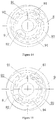
- a valve stem through-hole 90 is drilled on the static ceramic chip 9, and an arc-shaped hot water inlet passage 91, an arc-shaped hot water outlet passage 92, an arc-shaped cold water inlet passage 93 and an arc-shaped cold water outlet passage 94 are provided outside of the static ceramic chip valve stem through-hole 90.
- the hot water inlet passage 91 is located outside of the hot water outlet passage 92 and its length (arc length) is longer than that (arc length) of the hot water outlet passage 92
- the cold water inlet passage 93 is located outside of the cold water outlet passage 94 and its arc length is longer than that of the cold water outlet passage 94.
- the hot water inlet passage 91 is connected with the hot water incoming channel a in the valve core body 1
- the hot water outlet passage 92 is connected with the hot water outgoing channel c
- the cold water inlet passage 93 is connected with the cold water incoming channel b
- the cold water outlet passage 94 is connected with cold water outgoing channel d.
- the dynamic ceramic chip 8 is provided above the static ceramic chip 9, and a dynamic ceramic chip valve stem through-hole 80 is drilled on the dynamic ceramic chip 8.
- An eccentric hot water controlling channel 81 and an eccentric cold water controlling channel 82 are provided peripherally of the dynamic ceramic chip valve stem through-hole 80 at the bottom surface of the dynamic ceramic chip 8, furthermore, a pressure reduction through-hole 83 is drilled in both the hot water controlling channel 81 and the cold water controlling channel 82.
- the pressure reduction through-hole 83 provided can decrease the tensile force acting on the ceramic chip by dynamic pressure (water flow) and seal between the dynamic ceramic chip and the static ceramic chip can be enhanced, and meanwhile, the frictional force between the dynamic ceramic chip and the static ceramic chip can be decreased, so that the touch feel during the valve core rotating can be improved.
- the hot water channel shuts off when the hot water controlling channel 81 provided in the dynamic ceramic chip 8 is staggered from the hot water outlet passage 92 in the static ceramic chip 9, and meanwhile, the cold water channel shuts off when the cold water controlling channel 82 provided in the dynamic ceramic chip 8 is staggered from the cold water inlet passage 93 in the static ceramic chip 9.
- the hot water inlet passage 91 in the static ceramic chip 9 is connected by the hot water controlling channel 81 in the dynamic ceramic chip 8 with the hot water outlet passage 92 and then the hot water channel is opened; and meanwhile, the cold water inlet passage 93 in the static ceramic chip 9 is connected by the cold water controlling channel 82 in the dynamic ceramic chip 8 with the cold water outlet passage 94 and then the cold water channel is opened.
- the hot water and the cold water flow into the mixed water zone respectively through the hot water inlet 1b connected with the hot water outgoing channel c and the cold water inlet 1c connected with the cold water outgoing channel d.
- the temperature sensing portion of the thermo-sensitive element 10 can sense the temperature change of the mixed water and its push rod will extend or contract accordingly to drive the regulator 11 jog upwards or downwards inside the valve core body 1.
- the upper end and lower end of the water control portion 11-1 of the regulator 11 can control the opening degrees of the hot water inlet 1b and the cold water inlet 1c so as to control the dynamic balance between the hot incoming water and the cold incoming water and so that a constant temperature can be maintained (The constant temperature required can be set by rotating the temperature regulating valve stem.)
- the hot water and the cold water flow respectively into the regulator through the hot water inlet 1b and the cold water inlet 1c, and after mixing in the water mixing zone, the mixed water flows out through the mixed water outlet 30 in the valve seat 3.
- Temperature can be regulated in this way, i.e. the thermostatic valve stem (which drives the regulator for temperature regulating in turn) is driven by the drive lever seat.
- the cold incoming water and the hot incoming water can be shut off or open by the sliding dynamic ceramic chip to regulate the flow.
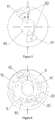
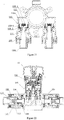
- the top view and bottom view of the valve core body respectively.
- the hot water incoming channel and the cold water incoming channel penetrates through the valve core body 1 separately , and the water incoming end face a1 of the hot water incoming channel and the water incoming end face b1 of the cold water incoming channel are located on the bottom surface of the valve core body and are arc-shaped (sector-shaped).
- the connection line between the midpoints of two arcs is taken as Axis x (the connection line between the geometrical centre lines of two sectors).
- the water outgoing end face a2 of the hot water incoming channel, the water outgoing end face b2 of the cold water incoming channel, the water incoming end face c1 of the hot water outgoing channel and the water incoming end face d1 of the cold water outgoing channel are provided respectively on the top surface of the valve core body and are sector-shaped.
- the water outgoing end face a2 of the hot water incoming channel, the water outgoing end face b2 of the cold water incoming channel, the water incoming end face c1 of the hot water outgoing channel and the water incoming end face d1 of the cold water outgoing channel are identical in shape and equal in size, arranged circumferentially and evenly spaced.
- the water outgoing end face a2 of the hot water incoming channel deflects an angle ⁇ relatively to Axis x, which is between 10-30°. Angle ⁇ is considered as 20° in this embodiment.
- a quartered-water route structure is adopted in the valve core body so that the water discharge area of the incoming water and the outgoing water and also the flow of the valve core can be increased. Since the position of water incoming is fixed (the positions on the water incoming end face a1 and the water incoming end face b1) and the quartered-water route rotates between 10-30°, the workmanship for the water incoming hole of the faucet can be improved and the water discharge area can be increased too. (As is shown in Figure 11 , the shadow part is the increased water discharge area after rotating 20°).
- the included angle A between the edge of the hot water outlet passage 92 and Axis x is 10° and the included angle B between the edge of the cold water outlet passage 94 and Axis x is 43°.
- the angle A can be between 5-15° and B between 40-50° in the present invention.
- the cold/hot water outlet passage in the static ceramic chip deflects a certain angle along with the quartered-water route in the valve core body, the valve core body can regulate the outgoing water in high or low temperature by regulating the water discharge area of the cold water and the hot water.
- the hot water inlet passage 91 in the static ceramic chip 9 is connected with the hot water outlet passage 92 by the hot water controlling channel 81, and the cold water inlet passage 93 in the static ceramic chip 9 is connected with the cold water outlet passage 94 by the cold water controlling channel 82, then both the hot water channel and cold water channel are opened. Since the hot water outlet passage 92 deflects a certain angle, the hot water controlling channel 81 are not opened coincidently with the hot water outlet passage 92 in a status of total cold water remained, thus the discharge area of the hot water is less than that of the cold water and the cold water flow is large, the water outgoing in lowest temperature can be achieved under the condition that the area of discharge area of cold water is biggest.
- the hot water inlet passage 91 in the static ceramic chip 9 is connected with the hot water outlet passage 92 by the hot water controlling channel 81, and the cold water inlet passage 93 in the static ceramic chip 9 is connected with the cold water outlet passage 94 by the cold water controlling channel 82, then both the hot water channel and cold water channel are opened. Since the cold water outlet passage 94 deflects a certain angle, the cold water controlling channel 82 are not opened coincidently with the cold water outlet passage 94 in a status of total hot water remained, thus the discharge area of cold water is less than that of hot water, the hot water flow is bigger, so that the water outgoing of valve core body in highest temperature is achieved under the condition of biggest discharge area of hot water.
- the hot water controlling channel 81 and the cold water controlling channel 82 are sector-shaped and both of the central angle is 60° so that the water flow is guaranteed in a status of the largest water discharge area during the dynamic ceramic chip rotating at the "switching on/off' position.
- the hot water controlling channel 81 and the cold water controlling channel can be identical in shape and be different also.
- the hot water controlling channel and the cold water controlling channel with different shapes can be adopted to keep the cold water incoming area equal to the hot water incoming area.
- the distance between the hot water controlling channel and the centre angle is different from that between the cold water controlling channel and the centre angle so that the hot water controlling channel is of an irregular shape, that is, a sector in "H" shape approximately, to keep the cold incoming water area equal to that of the hot incoming water.
- thermo-sensitive element Since the extension travel and contraction travel of thermo-sensitive element are caused by the temperature of hot water and cold water, and generally the rotation angle of the valve core of single-handle dual-control thermostatic valve is 120° and the discharge area of the ceramic chip is unchanged both in high or low temperature, in order to change the discharge area both in high or low temperature, travel of thermostatic valve core has to be increased; however, excessive travel will eliminate the self-locking of the thread, resulting into the inability for accurate temperature-regulating.
- the water discharge area of hot/cold water is changed due to the position of high/low temperature of the static ceramic chip so that both low/high temperate can be regulated by the valve core with a certain travel.
- thermo-sensitive element 10 is thread-connected with the regulator 11 so that the regulator can move along with the thermo-sensitive element.
- the upper end face of the water control portion 11-1 can be controlled to contact with the internal wall of the vale core body 1 when the regulator 11 moves up to the top, and the lower end face of the water control portion 11-1 can be controlled to contact with the upper end face of the valve seat 3 when the regulator 11 moves down to the bottom.
- the seal ring 11a is provided between the upper end face of the water control portion 11-1 and the internal walls of the valve core body 1 which contacts with the upper end face of the water control portion and between the lower end face of the water control portion 11-1 and the upper end face of the valve seat 3.
- the seal ring 11a is provided on both the upper end face and the lower end face of the water control portion 11-1, since there is a gap between the seal ring 11a, the internal wall of valve core body and the upper end face of the seat, the hot water and the cold water can flow into the regulator.
- the seal ring 11a is provided between the upper end face of the water control portion 11-1 and the internal wall of valve core body 1 and between the lower end face of water control portion 11-1 and the upper end face of the valve seat 3, and the seal ring is provided on the upper end face or the lower end face of the water control portion 11-1 or provided on the internal wall of valve core body 1 or the upper end face of valve seat 3.
- the sensor of the thermo-sensitive element 10 can sense the temperature of cold water, so that the push rod contracts to drive the thermo-sensitive element 10 to move upwards and the regulator 11 connected with the thermo-sensitive element 10 moves also upwards to the top accordingly, thus the upper end face of the water control portion 11-1 contacts with the internal wall of the valve core body 1 and the seal ring 11a shuts off the channel for the cold water flowing into the regulator 11 to interrupt the cold water supply.
- the sensor of the thermo-sensitive element 10 senses the temperature of hot water, so that the push rod extends to drive the thermo-sensitive element to move downwards and the regulator 11 connected with the thermo-sensitive element 10 moves also down to the bottom accordingly, thus the lower end face of the water control portion 11-1 contacts with the upper end face of the valve seat 3 and the seal ring 11a shuts off the channel for the hot water flowing into the regulator 11 to interrupt the hot water supply, ensuring two-way safety in case of emergent extreme temperature.
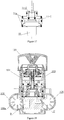
- the single-handle dual-control thermostatic faucet comprises a handle 101, a faucet shell 103, a thermostatic valve 104, a cold water incoming pipe 105, a hot water incoming pipe 106 and a mixed outgoing water pipe 107.
- the cold water incoming pipe 105, the hot water incoming pipe 106 and the mixed outgoing water pipe 107 are connected with the faucet shell 103.
- the thermostatic valve 104 is mounted inside the faucet shell 103 and the handle 101 is connected with the drive lever of the thermostatic valve 104 so that the faucet's switching on/off can be controlled when the handle swings upwards and downwards or rotates to drive the drive lever to move.
- the cold water flows into the thermostatic valve through the hot water incoming channel of the valve core body.
- the hot water flows into the thermostatic valve through the cold water incoming channel of the valve core body.
- the mixed water regulated by the thermostatic vale 104 flows out of the mixed water outgoing pipe 107 through the mixed water outlet of the valve core body.
- the water channel can be opened and shut off when the drive lever drives the dynamic ceramic chip to move.
- the temperature regulating valve stem moves upwards or downwards further to drive the regulator move upwards or downwards accordingly so that the opening degrees of both the cold water inlet and hot water inlet of the valve core are changed, the ratio of the cold incoming water to the hot incoming water is changed and the temperature of the mixed water is changed to perform the function of temperature regulation.
- the structure of the cold water incoming pipe 105 is identical to that of the hot water incoming pipe 106.
- the hot water incoming pipe for example, its structure is described as follows:
- a control cavity 106a is formed inside the hot water incoming pipe 106, and the front end of the hot water incoming pipe 106 comprises a connection portion 106b of the water incoming pipe.
- the end for the incoming water of the hot water incoming pipe 106 (control cavity) is defined as the water incoming end and another end opposite to the water incoming end, that is, the end for the outgoing water of the hot water incoming pipe 106 (control cavity) is defined as the water outgoing end.
- a piston part 108, a guiding part 109, a sealing pad support 110, a displacement elastomer 111 and a sealing pad 112 are provided inside the control cavity 106a of the hot water incoming pipe 106.
- the guiding part 109 is a hollow pipe body which is fixed inside the control cavity 106a and located at the water incoming end of the hot water incoming pipe 106 and is connected with the water inlet of the hot water incoming pipe 106 (control cavity).
- a piston part 108 is provided between the internal wall of the water outgoing end inside the hot water incoming pipe 106 and the guiding part 109.
- the piston part 108 is a hollow body also.
- the piston part 108 includes a water drawing portion 108-1, an elastomer action portion 108-2 and a contact portion 108-3.
- a seal ring is provided for sealing between the outer edge of the elastomer action portion 108-2 and the internal wall of the control cavity 106a to divide the internal part of hot water incoming pipe 106 into a water incoming zone and a water outgoing zone.
- the water drawing portion 108-1 extends into the internal cavity of the guiding part 109, a seal ring is provided for sealing between the outer edge of the water drawing portion 108-1 and the internal wall of guiding part 109, and the internal cavity of the piston part 108 is connected with the internal cavity of the guiding part 109.
- the contact portion 108-3 is against the internal wall of the water outgoing end of the hot water incoming pipe 106 (control cavity) or against the contact portion provided on the internal wall.
- a displacement elastomer 111 is provided between the elastomer action portion 108-2 of the piston part 108 and the guiding part 109. One end of the displacement elastomer 111 is against the elastomer action portion 108-2 and another end is against the guiding part 109 or against the internal wall of the control cavity 106a.
- the sealing pad support 110 is provided inside the guiding part 109.
- the sealing pad support 110 in this embodiment is fixed to the connecting portion 106b of the water incoming pipe.
- the sealing pad support 110 consists of a water discharge portion 110-1 and a supporting portion 110-2 disposed on the water discharge portion 110-1.
- Water discharge hole 110-1a drilled on the upper peripheral wall of the water discharge portion 110-1 whose position can be adjusted according to the installation position of the sealing pad support.
- the water discharge portion 110-1 is connected with the water inlet of the hot water incoming pipe 106. After flowing into the hot water incoming pipe 106, the hot water flows into the water discharge portion 110-1 and flows from the water discharge hole 110-1a into the internal cavity of the guiding part 109.
- the supporting portion 110-2 is integrally connected with the top of the water discharge portion 110-1, and the sealing pad 112 is provided on the end face of the supporting portion 110-2 by the top cap 113 and located at the water incoming side of the water discharge portion.
- the sealing pad 112 can change (open or shut off) the water route between the guiding part and the piston part.
- the hot water flows into the internal cavity of the piston part 108 through the water drawing portion 108-1 of the piston part 108, then flows into the water outgoing zone of the hot water incoming pipe and flows finally into the thermostatic valve from the water outgoing end of the hot water incoming pipe 106 through the hot water inlet 0. (Similarly, the cold water can flow into the thermostatic valve from the water outgoing end of the cold water incoming pipe 105 through the cold water inlet 0').
- the water pressure acting on the water outgoing end can pressurize on the contact portion 108-3 of the piston part 108 and the displacement elastomer 111 can also act on the elastomer action portion 108-3 of the piston part 108.
- the piston part 108 can move axially inside the control cavity 106a so as to change the distance (water route) between the water incoming end of the water drawing portion 108-1 of the piston part 108 and the sealing pad 112.
- the flow of incoming water becomes less when the drawing portion 108-1 is near the sealing pad 112, and the flow of incoming water becomes more when the water drawing portion 108-1 is far from the sealing pad 112.
- the guiding part 109 is fixed inside the hot water incoming pipe and is connected with the water inlet of the hot water incoming pipe 106.
- the upper end of the guiding part 109 extends into the water drawing portion 108-1 of the piston part 108, and a sealing ring is provided between the outer edge of the upper end of the guiding part 109 and the internal wall of the water drawing portion 108-1.
- the internal cavity of the piston part 108 is connected with that of the guiding part 109.
- a sealing ring is provided between the outer edge of the elastomer action portion 108-2 and the internal wall of the control cavity 106a, and the contact portion 108-3 is against the internal wall of the water outgoing end of the hot water incoming pipe 106.
- a displacement elastomer 111 is provided between the elsatomer action portion 108-2 of the piston part 108 and the guiding part 109, and one end of the displacement elastomer 111 is against the elstomer action portion 108-2 and other end is against the flange at bottom of the guiding part 109.
- a sealing pad installation portion 108-4 is provided inside the contact portion 108-3, and the sealing pad installation portion is integrally connected with the contact portion.
- the sealing pad 112 is provided on the bottom surface of the sealing pad installation portion 108-4 and is located at the water outgoing side of the guiding part.
- the difference between this embodiment and the third embodiment is:
- the water incoming direction of the cold/hot water inlet of the faucet in the third embodiment is parallel with the direction of the mixed water outlet, and the water incoming direction of the cold/hot water inlet is perpendicular to the direction of the mixed water outlet in this embodiment.
- the single-handle dual-control thermostatic faucet in this embodiment comprises a handle 101, a gland nut 102, a faucet shell 103, a thermostatic valve 104, a cold water incoming pipe 105, a hot water incoming pipe 106 and a mixed water outgoing pipe 107.
- the difference between this embodiment and the third embodiment is:
- the structure of the thermostatic valve 104 in this embodiment is identical to that of the thermostatic valve in the Application for a Patent Publication in China with Publication No.
- the thermostatic valve 104 comprises a driving lever 104-1, a drive plate 104-2, a dynamic ceramic chip 104-3, a static ceramic chip 104-4, a temperature regulating valve stem seat 104-5, a temperature regulating valve stem 104-6, a thermo-sensitive element 104-7, a regulator 104-8, a valve core body 104-9, a valve jacket 104-11, a seat 104-12 and a driving lever seat 104-13.
- the valve core body 104-9 in this embodiment includes a valve core body 104-9a and valve core jacket 104-9b which hermetically-fits with the valve core body 104-9a through a seal ring.
- the valve jacket 104-11 is connected with the top of the valve core body 104-9, the seat 104-12 is provided in the bottom of the valve core body 104-9.
- the seat 104-12 and the valve core body 104-9 form a space for accommodating the temperature regulating part and a water mixing zone.
- the dynamic ceramic chip 104-3 and the static ceramic chip 104-4 are provided inside the valve jacket 104-11, the latter is provided above the valve core body 104-9, the former is provided on the static ceramic chip 104-4.
- a hot water inlet passage, a hot water outlet passage a cold water inlet passage and a cold water outlet passage are provided separately on the static ceramic chip, and a hot water cavity and a cold water cavity are provided on the dynamic ceramic chip respectively.
- the hot water inlet passage, a hot water outlet passage a cold water inlet passage and a cold water outlet passage can be connected or shut off when the dynamic ceramic chip rotates.
- the handle 101 is connected with the driving lever 104-1 which is connected with the drive plate 104-2 through a pin roll.
- the driving lever 104-1 drives the dynamic ceramic chip 104-3 move though the drive plate 104-2.
- the driving lever 104-1 is driven to move, and further, to drive the dynamic ceramic chip 104-3 move for open and shut-off of the water channel.
- the upper end of the thermo-sensitive element 104-7 is against the end of the temperature regulating valve stem 104-6 and its lower end is indirectly against the regulator 104-8 by a spring.
- the thermo-sensitive element is connected with the regulator, when the thermo-sensitive element is moving, the regulator can be driven to move synchronously.
- the push rod of the thermo-sensitive element 104-7 can extend and contract accordingly so as to drive the regulator 104-8 to move upwards and downwards to further regulate the cold/hot water flow to obtain a balanced ratio of the cold/hot incoming water and to keep a stable temperature of the mixed water.
- the upper external wall of the temperature regulating valve stem 104-6 is connected through teeth with the drive plate 104-2, and the lower part thread-fits with the temperature regulating valve stem seat 104-5.
- the drive lever 104-1 When the handle 101 rotates, the drive lever 104-1 is driven to rotate so as to drive the drive plate 104-2 to rotate, the temperature regulating valve stem 104-6 moves upwards and downwards and further to drive the regulator 104-8 to move upwards and downwards so that the opening degree of both the cold water inlet and hot water inlet of the valve core changes, the ratio of the cold incoming water to the hot incoming water changes and the temperature of the mixed water changes for proper function of temperature regulation.
- the supporting portion of the regulator in this embodiment is indirectly against the seat, a seal ring is provided on both the upper end face and lower end face respectively of the water control portion of the regulator.
- the seal ring When the regulator moves upwards to the upper end face of its water control portion to contact with the internal wall of the valve core body, the seal ring will close the gap between the both; when the regulator downwards to the lower end face of its water control portion to contact with the upper end face of the seat, the seal ring will close the gap between the both.
- each section is described in a progressive way, the difference with other sections is emphasized in each section; for those similar or identical parts, each section can be referred to one another.
- the combinational relationship among those components/parts is not limited only to the pattern known from the embodiments, and those skilled in the arts can materialize or use the present invention according to the above description of the embodiments known to the public. It will be obvious for those skilled in the art to modify those embodiments for many times.
Landscapes
- Engineering & Computer Science (AREA)
- General Engineering & Computer Science (AREA)
- Physics & Mathematics (AREA)
- General Physics & Mathematics (AREA)
- Automation & Control Theory (AREA)
- Mechanical Engineering (AREA)
- Multiple-Way Valves (AREA)
- Domestic Plumbing Installations (AREA)
Claims (11)
- Vanne thermostatique à double commande et manette unique comprenant :un corps de noyau de vanne (1),une chemise de vanne (2) raccordée hermétiquement avec la partie supérieure du corps de noyau de vanne, etun siège de vanne (3) situé à la base du corps de noyau de vanne, oùle corps de noyau de vanne et le siège de vanne forment un espace pour loger une pièce de régulation de température et une zone de mélange d'eau ; une pièce d'écoulement et une pièce de commande sont prévues dans la chemise de vanne, tandis que l'extrémité supérieure d'un levier d'entraînement (6) de la pièce de commande s'étend vers le haut hors de la chemise de vanne,un canal d'arrivée d'eau chaude (a), un canal d'arrivée d'eau froide (b), un canal de sortie d'eau chaude (c) et un canal de sortie d'eau froide (d) sont prévus séparément dans le corps de noyau de vanne, et le canal d'arrivée d'eau chaude et le canal d'arrivée d'eau froide pénètrent dans le corps de noyau de vanne ; le corps de noyau de vanne comporte une entrée d'eau chaude (1b) qui se raccorde avec le canal de sortie d'eau chaude et la zone de mélange d'eau et une entrée d'eau froide (1c) qui se raccorde avec le canal de sortie d'eau froide et la zone de mélange d'eau, et l'entrée d'eau chaude et l'entrée d'eau froide sont situées à des positions à différentes hauteurs dans le corps de noyau de vanne,une pastille céramique statique (9), comportant un passage d'entrée d'eau chaude (91), un passage de sortie d'eau chaude (92), un passage d'entrée d'eau froide (93) et un passage de sortie d'eau froide (94), est située au-dessus du corps de noyau de vanne dans la chemise de vanne, une pastille céramique dynamique (8) comportant un canal de commande d'eau chaude (81) et un canal de commande d'eau froide (82) est située sur la pastille céramique statique, la pastille céramique dynamique est raccordée avec la pièce de commande et peut subir un mouvement de rotation et de translation par la pièce de commande, le passage d'entrée d'eau chaude, le passage de sortie d'eau chaude, le passage d'entrée d'eau froide et le passage de sortie d'eau froide étant raccordés en correspondance avec le canal d'arrivée d'eau chaude, le canal de sortie d'eau chaude, le canal d'arrivée d'eau froide et le canal de sortie d'eau froide du corps de noyau de vanne, respectivement, le canal de commande d'eau chaude pouvant ouvrir ou fermer à la fois le passage d'entrée d'eau chaude et le passage de sortie d'eau chaude sur la pastille céramique statique, et le canal de commande d'eau froide pouvant ouvrir ou fermer à la fois le passage d'entrée d'eau froide et le passage de sortie d'eau froide sur la pastille céramique statique,une sortie d'eau mélangée (30) est située sur le siège de vanne et raccordée avec la zone de mélange d'eau,une face d'extrémité d'arrivée d'eau (a1) du canal d'arrivée d'eau chaude et une face d'extrémité d'arrivée d'eau (b1) du canal d'arrivée d'eau froide étant situées sur la surface inférieure du corps de noyau de vanne et étant de forme arquée et la ligne de connexion entre les points médians des deux arcs étant l'axe X,caractérisée en ce qu'une face d'extrémité de sortie d'eau (a2) du canal d'arrivée d'eau chaude dévie de 10° à 30° par rapport à l'axe X, l'angle inclus entre le bord du canal de sortie d'eau chaude et l'axe X étant de 5° à 15° et l'angle inclus entre le bord du canal de sortie d'eau froide et l'axe X étant de 40° à 50°.
- Vanne thermostatique à double commande et manette unique selon la revendication 1, dans laquelle la pièce de régulation de température comprend une tige de vanne de régulation de température (4), un siège de tige de vanne de régulation de température (5), un élément thermosensible (10), un régulateur (11), et un ressort de rappel (14), dans laquelle un orifice (1a) pour la tige de vanne de régulation de température est situé au sommet du corps de noyau de vanne (1) et le siège de tige de vanne de régulation de température est fixé à la paroi interne de l'orifice de tige de vanne de régulation de température, la tige de vanne de régulation de température s'ajuste par vissage avec le siège de tige de vanne de régulation de température et son extrémité supérieure s'étend vers le haut ;
le régulateur comprenant une partie de commande d'eau (11-1) et une partie de support (11-2) est disposé entre le siège de tige de vanne de régulation de température et le siège de vanne (3) et la paroi périphérique externe de la partie de commande d'eau se trouve contre la paroi interne du corps de noyau de vanne et la partie de support se trouve contre le fond du siège de tige de vanne de régulation de température, l'extrémité supérieure et l'extrémité inférieure de la partie de commande d'eau sont situées au niveau de l'entrée d'eau chaude (1b) et de l'entrée d'eau froide (1c) du corps de noyau de vanne, respectivement ; un anneau d'étanchéité d'isolation chaud/froid (19) entre l'entrée d'eau chaude et l'entrée d'eau froide est situé sur la paroi périphérique externe de la partie de commande d'eau, l'extrémité supérieure de l'élément thermosensible est située indirectement contre la tige de vanne par un ressort de verrouillage (17) et son extrémité inférieure est située indirectement contre le siège de vanne par un ressort de rappel (14), l'extrémité inférieure et l'extrémité supérieure du ressort de rappel étant situées contre le siège de vanne et le régulateur, respectivement. - Vanne thermostatique à double commande et manette unique selon la revendication 1, dans laquelle la pièce de commande comprend le levier d'entraînement (6), un siège de levier d'entraînement (7), une plaque d'entraînement (12) et l'organe d'entraînement de plaque d'entraînement (13), le siège de levier d'entraînement et la plaque d'entraînement sont logés sur la partie supérieure de la cavité interne dans la chemise de vanne (2), et la plaque d'entraînement est située au-dessous du siège de levier d'entraînement et raccordée avec la pastille céramique dynamique (8), les dents externes à l'extrémité supérieure de la tige de vanne de régulation de température (4) s'emboîtent avec les dents internes dans l'orifice central du siège de levier d'entraînement, la partie inférieure du levier d'entraînement pénètre dans le siège de levier d'entraînement et est raccordée avec le siège de levier par un goujon (21), l'extrémité inférieure du levier d'entraînement étant encastrée dans, et fixée à, l'organe d'entraînement de levier d'entraînement sur la plaque d'entraînement.
- Vanne thermostatique à double commande et manette unique selon la revendication 1, dans laquelle le passage d'entrée d'eau chaude (91) de la pastille céramique statique (9) est situé à l'extérieur du passage de sortie d'eau chaude (92) et est plus long que ce dernier ; le passage d'entrée d'eau froide (93) est situé à l'extérieur du passage de sortie d'eau froide (94) et est plus long que ce dernier.
- Vanne thermostatique à double commande et manette unique selon la revendication 1 ou 4, dans laquelle la face d'extrémité de sortie d'eau (a2) du canal d'arrivée d'eau chaude (a), une face d'extrémité de sortie d'eau (b2) du canal d'arrivée d'eau froide (b), une face d'extrémité d'arrivée d'eau (c1) du canal de sortie d'eau chaude (c) et une face d'extrémité d'arrivée d'eau (d1) du canal de sortie d'eau froide (d) sont situées sur la surface supérieure du corps de noyau de vanne (1) et sont en forme de secteur ; et la face d'extrémité de sortie d'eau du canal d'arrivée d'eau chaude, la face d'extrémité de sortie d'eau du canal d'arrivée d'eau froide, la face d'extrémité d'arrivée d'eau du canal de sortie d'eau chaude et la face d'extrémité d'arrivée d'eau du canal de sortie d'eau froide ont une forme et une dimension identiques et sont réparties uniformément le long de la circonférence à un certain intervalle.
- Vanne thermostatique à double commande et manette unique selon la revendication 2, dans laquelle l'élément thermosensible (10) est raccordé avec le régulateur (11) pour entraîner ce dernier en déplacement,
un anneau d'étanchéité (11a) est disposé entre la face d'extrémité supérieure de la partie de commande d'eau (11-1) du régulateur et la paroi interne du corps de noyau de vanne (1) et entre la face d'extrémité inférieure de la partie de commande d'eau et la face d'extrémité supérieure du siège de vanne (3), lorsque la face d'extrémité supérieure de la partie de commande d'eau entre en contact avec la paroi interne du corps de noyau de vanne, l'anneau d'étanchéité ferme l'espace entre la face d'extrémité supérieure de la partie de commande d'eau et la paroi interne du corps de noyau de vanne ; lorsque la face d'extrémité inférieure de la partie de commande d'eau entre en contact avec la face d'extrémité supérieure du siège de vanne, l'anneau d'étanchéité ferme l'espace entre la face d'extrémité inférieure de la partie de commande d'eau et la face d'extrémité supérieure du siège de vanne. - Vanne thermostatique à double commande et manette unique selon la revendication 6, dans laquelle l'anneau d'étanchéité (11a) est disposé sur la face d'extrémité supérieure et la face d'extrémité inférieure de la partie de commande d'eau (11-1).
- Robinet thermostatique à double commande et manette unique équipé d'une vanne thermostatique à double commande et manette unique selon l'une quelconque des revendications 1 à 7, le robinet thermostatique à double commande et manette unique comprenant une coque de robinet (103), une vanne thermostatique (104) située dans la coque de robinet, une manette (101) qui commande la vanne thermostatique, un tuyau d'arrivée d'eau froide (105), un tuyau d'arrivée d'eau chaude (106) et un tuyau de sortie d'eau mélangée (107) qui sont raccordés avec la coque de robinet, la manette étant raccordée avec le levier d'entraînement (6) de la vanne thermostatique.
- Robinet thermostatique à double commande et manette unique selon la revendication 8, dans lequel le tuyau d'arrivée d'eau froide (105) et le tuyau d'arrivée d'eau chaude (106) forment une cavité de commande interne (106a), respectivement, à l'intérieur de la cavité de commande, étant prévus les éléments suivants :une pièce de guidage creuse (109) qui est raccordée avec l'entrée d'eau de la cavité de commande ;une pièce formant piston (108) disposée entre la pièce de guidage et l'extrémité de sortie d'eau de la cavité de commande ; la cavité interne de la pièce formant piston est raccordée avec la cavité interne de la pièce de guidage, et la pièce formant piston comporte une partie de soutirage d'eau (108-1), une partie d'action en élastomère (108-2) et une partie de contact (108-3) qui sont raccordées successivement les unes aux autres et peuvent se déplacer axialement à l'intérieur de la cavité de commande, la partie de soutirage d'eau étant encastrée dans, et raccordée avec, la pièce de guidage, la partie de contact étant située contre la sortie d'eau de la cavité de commande, et un anneau d'étanchéité étant disposé entre le bord externe de la partie d'action en élastomère et la paroi interne de la cavité de commande ;un élastomère de déplacement (111) disposé entre la partie d'action en élastomère et la pièce de guidage ;un patin d'étanchéité (112) situé sur sa partie d'installation (108-4) peut modifier le trajet de l'eau entre la pièce de guidage et la pièce formant piston.
- Robinet thermostatique à double commande et manette unique selon la revendication 9, dans lequel la partie d'installation de patin d'étanchéité (108-4) est un support (110) pour le patin d'étanchéité (112) situé dans la partie de connexion (106b) du tuyau d'arrivée d'eau, et le support de patin d'étanchéité comprend une partie de décharge d'eau (110-1) comportant des orifices de décharge d'eau (110-1a) sur sa paroi périphérique raccordée avec l'entrée d'eau de la cavité de commande et une partie de support (110-2) située sur la partie de décharge d'eau, et le patin d'étanchéité est situé sur la face d'extrémité de la partie de support ; et
la partie de soutirage d'eau (108-1) s'étend dans la cavité interne de la pièce de guidage (109), et le patin d'étanchéité est situé au niveau du côté d'arrivée d'eau de la partie de soutirage d'eau. - Robinet thermostatique à double commande et manette unique selon la revendication 10, dans lequel l'extrémité supérieure de la pièce de guidage (109) s'étend dans la partie de soutirage d'eau (108-1) de la pièce formant piston (108), la partie d'installation (108-4) pour le patin d'étanchéité (112) est située à l'intérieur de la partie de contact (108-3), et le patin d'étanchéité est situé sur la surface inférieure de la partie d'installation du patin d'étanchéité et est situé au niveau du côté d'arrivée d'eau de la pièce de guidage.
Applications Claiming Priority (3)
| Application Number | Priority Date | Filing Date | Title |
|---|---|---|---|
| CN201420464057.2U CN204164426U (zh) | 2014-08-15 | 2014-08-15 | 一种单柄双控恒温阀 |
| CN201420471783.7U CN204201177U (zh) | 2014-08-20 | 2014-08-20 | 耐高压单柄双控恒温恒压龙头 |
| CN201420820043.XU CN204592396U (zh) | 2014-12-19 | 2014-12-19 | 单柄双控恒温阀及恒温龙头 |
Publications (3)
| Publication Number | Publication Date |
|---|---|
| EP2985668A2 EP2985668A2 (fr) | 2016-02-17 |
| EP2985668A3 EP2985668A3 (fr) | 2016-06-22 |
| EP2985668B1 true EP2985668B1 (fr) | 2018-07-25 |
Family
ID=52991442
Family Applications (2)
| Application Number | Title | Priority Date | Filing Date |
|---|---|---|---|
| EP15155781.6A Not-in-force EP2985392B1 (fr) | 2014-08-15 | 2015-02-19 | Robinet thermostatiques de double commande à manche unique |
| EP15155716.2A Not-in-force EP2985668B1 (fr) | 2014-08-15 | 2015-02-19 | Soupape et robinet thermostatiques à double commande à manche unique |
Family Applications Before (1)
| Application Number | Title | Priority Date | Filing Date |
|---|---|---|---|
| EP15155781.6A Not-in-force EP2985392B1 (fr) | 2014-08-15 | 2015-02-19 | Robinet thermostatiques de double commande à manche unique |
Country Status (3)
| Country | Link |
|---|---|
| US (2) | US9720426B2 (fr) |
| EP (2) | EP2985392B1 (fr) |
| AU (2) | AU2015213363B2 (fr) |
Families Citing this family (25)
| Publication number | Priority date | Publication date | Assignee | Title |
|---|---|---|---|---|
| DE202017100756U1 (de) * | 2017-02-13 | 2017-03-20 | Flühs Drehtechnik GmbH | Thermostat-Mischventil |
| DE102018004082B4 (de) * | 2017-05-24 | 2023-07-06 | Mann+Hummel Gmbh | Schaltventil zum Einstellen eines Fluidstroms |
| CN107559490B (zh) * | 2017-08-22 | 2024-07-05 | 宁波优尔多电器有限公司 | 电热水龙头 |
| CN108061178B (zh) * | 2018-01-11 | 2023-10-27 | 漳州松霖智能家居有限公司 | 按压切换阀芯 |
| CN109404560B (zh) * | 2018-01-26 | 2024-05-28 | 台州市国人温控卫浴科技有限公司 | 一种冷热水混合后感温出水的恒温阀芯 |
| JP7166823B2 (ja) * | 2018-07-18 | 2022-11-08 | 日本サーモスタット株式会社 | 湯水混合栓 |
| CN109027306B (zh) * | 2018-10-30 | 2024-07-16 | 泉州万滤达净水科技有限公司 | 一种入墙式三合一滤水龙头 |
| CN110056676A (zh) * | 2019-02-01 | 2019-07-26 | 厦门水芯科技有限公司 | 一种带流量控制的单把手恒温阀芯及出水龙头 |
| CN109899589B (zh) * | 2019-04-02 | 2023-03-24 | 开平市水口镇品阳五金加工店 | 一体式多功能控水阀芯 |
| CN110469693B (zh) * | 2019-09-17 | 2024-04-02 | 上海易匠阀芯有限公司 | 一种恒温阀芯及恒温水龙头 |
| CN111042764B (zh) * | 2019-12-09 | 2021-10-01 | 陕西航天泵阀科技集团有限公司 | 一种天然气井口调节急断装置 |
| CN111677908A (zh) * | 2020-05-21 | 2020-09-18 | 厦门建霖健康家居股份有限公司 | 一种水路控制装置及出水装置 |
| CN111998099A (zh) * | 2020-09-30 | 2020-11-27 | 开平市汉格联祥卫浴有限公司 | 一种带净水装置的抽拉式龙头 |
| CN112146275B (zh) * | 2020-10-12 | 2021-11-05 | 诸暨市佳哲卫浴有限公司 | 一种热水器用即热水管 |
| CN114962728A (zh) * | 2021-02-23 | 2022-08-30 | 宁波万海阀门科技有限公司 | 兼具混水分水功能的一体式水龙头阀芯 |
| CN112814087A (zh) * | 2021-03-04 | 2021-05-18 | 何仁熙 | 一种洗碗水龙头 |
| CN112923102B (zh) * | 2021-03-19 | 2025-06-17 | 唐山惠达(集团)洁具有限公司 | 一种侧开面盆龙头 |
| CN113000515A (zh) * | 2021-04-24 | 2021-06-22 | 丁博远 | 一种集调温、按压操控于一体的机械式增压喷洗杯具装置 |
| CN114233897A (zh) * | 2021-12-28 | 2022-03-25 | 阿诗丹顿电气有限公司 | 一种集成式调温恒温阀 |
| CN115111401B (zh) * | 2022-01-28 | 2026-02-24 | 漳州松霖智能家居有限公司 | 厨卫领域水路控制装置、调温阀芯及龙头装置 |
| CN114593233A (zh) * | 2022-03-17 | 2022-06-07 | 陈晓东 | 一种精确控制出水温度的恒温阀 |
| CN114587768A (zh) * | 2022-03-17 | 2022-06-07 | 余姚市冬暖阳电器科技有限公司 | 一种热水袋及与该热水袋配套的加热器 |
| CN115325215B (zh) * | 2022-08-15 | 2024-09-03 | 堡德(中国)卫浴有限公司 | 一种节水水龙头 |
| CN115854065A (zh) * | 2022-12-14 | 2023-03-28 | 开平市福特温控卫浴有限公司 | 一种恒温阀芯 |
| CN116006727A (zh) * | 2023-01-10 | 2023-04-25 | 开平市翰森卫浴有限公司 | 一种多档分水调温调流量阀芯、出水装置 |
Family Cites Families (12)
| Publication number | Priority date | Publication date | Assignee | Title |
|---|---|---|---|---|
| US4640457A (en) * | 1982-03-03 | 1987-02-03 | Masco Corporation | Thermostatic valve assembly |
| DE3811708A1 (de) * | 1988-04-08 | 1989-10-19 | Ideal Standard | Sanitaeres mischventil |
| SE507634C2 (sv) * | 1991-03-14 | 1998-06-29 | Masco Corp | Termostatiskt kontrollerade blandningsventil, speciellt av engreppstyp |
| US6263899B1 (en) * | 2000-03-03 | 2001-07-24 | Symmons Industries, Inc. | Mixing valves with ceramic flow control elements |
| FR2841348B1 (fr) * | 2002-06-21 | 2004-09-24 | Vernet Sa | Cartouche thermostatique monocommande, a disques en ceramique |
| CN201034188Y (zh) * | 2007-03-20 | 2008-03-12 | 谢庆俊 | 单柄恒温阀芯 |
| US8322377B2 (en) * | 2007-10-04 | 2012-12-04 | David Di Nunzio | Valve |
| FR2940397B1 (fr) * | 2008-12-22 | 2014-06-20 | Vernet | Cartouche thermostatique monocommande et robinet mitigeur comportant une telle cartouche |
| CN201706022U (zh) * | 2010-04-03 | 2011-01-12 | 珠海市舒丽玛温控卫浴设备有限公司 | 限压控制阀 |
| CN201802925U (zh) * | 2010-08-18 | 2011-04-20 | 珠海市舒丽玛温控卫浴设备有限公司 | 新型单柄连续型恒温电热水器龙头 |
| CN202914809U (zh) * | 2012-05-16 | 2013-05-01 | 珠海市舒丽玛温控卫浴设备有限公司 | 适用于太阳能热水器的单柄双控恒温龙头 |
| CN103912693B (zh) | 2014-02-28 | 2017-02-15 | 珠海市舒丽玛温控卫浴设备有限公司 | 具有微调功能的单柄双控恒温阀 |
-
2015
- 2015-01-15 US US14/597,401 patent/US9720426B2/en not_active Expired - Fee Related
- 2015-01-15 US US14/597,409 patent/US9915960B2/en not_active Expired - Fee Related
- 2015-02-19 EP EP15155781.6A patent/EP2985392B1/fr not_active Not-in-force
- 2015-02-19 EP EP15155716.2A patent/EP2985668B1/fr not_active Not-in-force
- 2015-08-13 AU AU2015213363A patent/AU2015213363B2/en not_active Ceased
- 2015-08-13 AU AU2015213357A patent/AU2015213357B2/en not_active Ceased
Non-Patent Citations (1)
| Title |
|---|
| None * |
Also Published As
| Publication number | Publication date |
|---|---|
| EP2985392A3 (fr) | 2016-07-13 |
| US9915960B2 (en) | 2018-03-13 |
| EP2985392A2 (fr) | 2016-02-17 |
| AU2015213357B2 (en) | 2019-06-27 |
| AU2015213363A1 (en) | 2016-03-03 |
| AU2015213357A1 (en) | 2016-03-03 |
| EP2985668A2 (fr) | 2016-02-17 |
| AU2015213363B2 (en) | 2019-06-20 |
| US20160048141A1 (en) | 2016-02-18 |
| EP2985392B1 (fr) | 2018-07-25 |
| US20160048140A1 (en) | 2016-02-18 |
| EP2985668A3 (fr) | 2016-06-22 |
| US9720426B2 (en) | 2017-08-01 |
Similar Documents
| Publication | Publication Date | Title |
|---|---|---|
| EP2985392B1 (fr) | Robinet thermostatiques de double commande à manche unique | |
| US6557770B2 (en) | Thermostatic cartridge for mixer taps | |
| US5340018A (en) | Thermostatically controlled mixing valve | |
| CN204164426U (zh) | 一种单柄双控恒温阀 | |
| AU2370695A (en) | Thermostatic mixing device | |
| CN108474486B (zh) | 热水混合水龙头用流体控制阀装置 | |
| CN204592396U (zh) | 单柄双控恒温阀及恒温龙头 | |
| US4116377A (en) | Mixer unit with thermostat-controlled valves | |
| CN104265951A (zh) | 单柄双控恒温阀 | |
| CN106678397A (zh) | 一种双控恒温阀芯 | |
| CN204201177U (zh) | 耐高压单柄双控恒温恒压龙头 | |
| US11821541B2 (en) | Valve for a sanitary faucet having a diaphragm valve and an adjustable control rod | |
| CN110056676A (zh) | 一种带流量控制的单把手恒温阀芯及出水龙头 | |
| JPH0456192B2 (fr) | ||
| CN209925684U (zh) | 一种带流量控制的单把手恒温阀芯及出水龙头 | |
| CN104315202B (zh) | 单柄双控恒温恒压龙头 | |
| CN216975876U (zh) | 套管式双阀芯组件及含有其的主、辅路独立调节的三通阀 | |
| CN218440805U (zh) | 一种厨卫领域水路控制装置、调温阀芯及龙头装置 | |
| CN110285255A (zh) | 一种双控阀芯 | |
| EP1566584B1 (fr) | Soupape de régulation | |
| JP2023014395A5 (fr) | ||
| JPH07248067A (ja) | リリーフ弁 | |
| CN211667195U (zh) | 一种冷热调温延时混合阀 | |
| US2573062A (en) | Hot and cold water control valve | |
| JP5936029B2 (ja) | 流量調整弁 |
Legal Events
| Date | Code | Title | Description |
|---|---|---|---|
| PUAI | Public reference made under article 153(3) epc to a published international application that has entered the european phase |
Free format text: ORIGINAL CODE: 0009012 |
|
| AK | Designated contracting states |
Kind code of ref document: A2 Designated state(s): AL AT BE BG CH CY CZ DE DK EE ES FI FR GB GR HR HU IE IS IT LI LT LU LV MC MK MT NL NO PL PT RO RS SE SI SK SM TR |
|
| AX | Request for extension of the european patent |
Extension state: BA ME |
|
| PUAL | Search report despatched |
Free format text: ORIGINAL CODE: 0009013 |
|
| AK | Designated contracting states |
Kind code of ref document: A3 Designated state(s): AL AT BE BG CH CY CZ DE DK EE ES FI FR GB GR HR HU IE IS IT LI LT LU LV MC MK MT NL NO PL PT RO RS SE SI SK SM TR |
|
| AX | Request for extension of the european patent |
Extension state: BA ME |
|
| RIC1 | Information provided on ipc code assigned before grant |
Ipc: G05D 23/13 20060101AFI20160519BHEP |
|
| 17P | Request for examination filed |
Effective date: 20161019 |
|
| RBV | Designated contracting states (corrected) |
Designated state(s): AL AT BE BG CH CY CZ DE DK EE ES FI FR GB GR HR HU IE IS IT LI LT LU LV MC MK MT NL NO PL PT RO RS SE SI SK SM TR |
|
| GRAP | Despatch of communication of intention to grant a patent |
Free format text: ORIGINAL CODE: EPIDOSNIGR1 |
|
| STAA | Information on the status of an ep patent application or granted ep patent |
Free format text: STATUS: GRANT OF PATENT IS INTENDED |
|
| INTG | Intention to grant announced |
Effective date: 20180322 |
|
| GRAS | Grant fee paid |
Free format text: ORIGINAL CODE: EPIDOSNIGR3 |
|
| GRAA | (expected) grant |
Free format text: ORIGINAL CODE: 0009210 |
|
| STAA | Information on the status of an ep patent application or granted ep patent |
Free format text: STATUS: THE PATENT HAS BEEN GRANTED |
|
| AK | Designated contracting states |
Kind code of ref document: B1 Designated state(s): AL AT BE BG CH CY CZ DE DK EE ES FI FR GB GR HR HU IE IS IT LI LT LU LV MC MK MT NL NO PL PT RO RS SE SI SK SM TR |
|
| REG | Reference to a national code |
Ref country code: GB Ref legal event code: FG4D |
|
| REG | Reference to a national code |
Ref country code: CH Ref legal event code: EP |
|
| REG | Reference to a national code |
Ref country code: AT Ref legal event code: REF Ref document number: 1022423 Country of ref document: AT Kind code of ref document: T Effective date: 20180815 |
|
| REG | Reference to a national code |
Ref country code: IE Ref legal event code: FG4D |
|
| REG | Reference to a national code |
Ref country code: DE Ref legal event code: R096 Ref document number: 602015013860 Country of ref document: DE |
|
| REG | Reference to a national code |
Ref country code: NL Ref legal event code: MP Effective date: 20180725 |
|
| REG | Reference to a national code |
Ref country code: LT Ref legal event code: MG4D |
|
| PG25 | Lapsed in a contracting state [announced via postgrant information from national office to epo] |
Ref country code: NL Free format text: LAPSE BECAUSE OF FAILURE TO SUBMIT A TRANSLATION OF THE DESCRIPTION OR TO PAY THE FEE WITHIN THE PRESCRIBED TIME-LIMIT Effective date: 20180725 |
|
| REG | Reference to a national code |
Ref country code: AT Ref legal event code: MK05 Ref document number: 1022423 Country of ref document: AT Kind code of ref document: T Effective date: 20180725 |
|
| PG25 | Lapsed in a contracting state [announced via postgrant information from national office to epo] |
Ref country code: LT Free format text: LAPSE BECAUSE OF FAILURE TO SUBMIT A TRANSLATION OF THE DESCRIPTION OR TO PAY THE FEE WITHIN THE PRESCRIBED TIME-LIMIT Effective date: 20180725 Ref country code: RS Free format text: LAPSE BECAUSE OF FAILURE TO SUBMIT A TRANSLATION OF THE DESCRIPTION OR TO PAY THE FEE WITHIN THE PRESCRIBED TIME-LIMIT Effective date: 20180725 Ref country code: SE Free format text: LAPSE BECAUSE OF FAILURE TO SUBMIT A TRANSLATION OF THE DESCRIPTION OR TO PAY THE FEE WITHIN THE PRESCRIBED TIME-LIMIT Effective date: 20180725 Ref country code: BG Free format text: LAPSE BECAUSE OF FAILURE TO SUBMIT A TRANSLATION OF THE DESCRIPTION OR TO PAY THE FEE WITHIN THE PRESCRIBED TIME-LIMIT Effective date: 20181025 Ref country code: PL Free format text: LAPSE BECAUSE OF FAILURE TO SUBMIT A TRANSLATION OF THE DESCRIPTION OR TO PAY THE FEE WITHIN THE PRESCRIBED TIME-LIMIT Effective date: 20180725 Ref country code: NO Free format text: LAPSE BECAUSE OF FAILURE TO SUBMIT A TRANSLATION OF THE DESCRIPTION OR TO PAY THE FEE WITHIN THE PRESCRIBED TIME-LIMIT Effective date: 20181025 Ref country code: FI Free format text: LAPSE BECAUSE OF FAILURE TO SUBMIT A TRANSLATION OF THE DESCRIPTION OR TO PAY THE FEE WITHIN THE PRESCRIBED TIME-LIMIT Effective date: 20180725 Ref country code: GR Free format text: LAPSE BECAUSE OF FAILURE TO SUBMIT A TRANSLATION OF THE DESCRIPTION OR TO PAY THE FEE WITHIN THE PRESCRIBED TIME-LIMIT Effective date: 20181026 Ref country code: AT Free format text: LAPSE BECAUSE OF FAILURE TO SUBMIT A TRANSLATION OF THE DESCRIPTION OR TO PAY THE FEE WITHIN THE PRESCRIBED TIME-LIMIT Effective date: 20180725 Ref country code: IS Free format text: LAPSE BECAUSE OF FAILURE TO SUBMIT A TRANSLATION OF THE DESCRIPTION OR TO PAY THE FEE WITHIN THE PRESCRIBED TIME-LIMIT Effective date: 20181125 |
|
| PG25 | Lapsed in a contracting state [announced via postgrant information from national office to epo] |
Ref country code: HR Free format text: LAPSE BECAUSE OF FAILURE TO SUBMIT A TRANSLATION OF THE DESCRIPTION OR TO PAY THE FEE WITHIN THE PRESCRIBED TIME-LIMIT Effective date: 20180725 Ref country code: LV Free format text: LAPSE BECAUSE OF FAILURE TO SUBMIT A TRANSLATION OF THE DESCRIPTION OR TO PAY THE FEE WITHIN THE PRESCRIBED TIME-LIMIT Effective date: 20180725 Ref country code: AL Free format text: LAPSE BECAUSE OF FAILURE TO SUBMIT A TRANSLATION OF THE DESCRIPTION OR TO PAY THE FEE WITHIN THE PRESCRIBED TIME-LIMIT Effective date: 20180725 |
|
| REG | Reference to a national code |
Ref country code: DE Ref legal event code: R097 Ref document number: 602015013860 Country of ref document: DE |
|
| PG25 | Lapsed in a contracting state [announced via postgrant information from national office to epo] |
Ref country code: IT Free format text: LAPSE BECAUSE OF FAILURE TO SUBMIT A TRANSLATION OF THE DESCRIPTION OR TO PAY THE FEE WITHIN THE PRESCRIBED TIME-LIMIT Effective date: 20180725 Ref country code: RO Free format text: LAPSE BECAUSE OF FAILURE TO SUBMIT A TRANSLATION OF THE DESCRIPTION OR TO PAY THE FEE WITHIN THE PRESCRIBED TIME-LIMIT Effective date: 20180725 Ref country code: CZ Free format text: LAPSE BECAUSE OF FAILURE TO SUBMIT A TRANSLATION OF THE DESCRIPTION OR TO PAY THE FEE WITHIN THE PRESCRIBED TIME-LIMIT Effective date: 20180725 Ref country code: EE Free format text: LAPSE BECAUSE OF FAILURE TO SUBMIT A TRANSLATION OF THE DESCRIPTION OR TO PAY THE FEE WITHIN THE PRESCRIBED TIME-LIMIT Effective date: 20180725 Ref country code: ES Free format text: LAPSE BECAUSE OF FAILURE TO SUBMIT A TRANSLATION OF THE DESCRIPTION OR TO PAY THE FEE WITHIN THE PRESCRIBED TIME-LIMIT Effective date: 20180725 |
|
| PG25 | Lapsed in a contracting state [announced via postgrant information from national office to epo] |
Ref country code: SK Free format text: LAPSE BECAUSE OF FAILURE TO SUBMIT A TRANSLATION OF THE DESCRIPTION OR TO PAY THE FEE WITHIN THE PRESCRIBED TIME-LIMIT Effective date: 20180725 Ref country code: SM Free format text: LAPSE BECAUSE OF FAILURE TO SUBMIT A TRANSLATION OF THE DESCRIPTION OR TO PAY THE FEE WITHIN THE PRESCRIBED TIME-LIMIT Effective date: 20180725 Ref country code: DK Free format text: LAPSE BECAUSE OF FAILURE TO SUBMIT A TRANSLATION OF THE DESCRIPTION OR TO PAY THE FEE WITHIN THE PRESCRIBED TIME-LIMIT Effective date: 20180725 |
|
| PLBE | No opposition filed within time limit |
Free format text: ORIGINAL CODE: 0009261 |
|
| STAA | Information on the status of an ep patent application or granted ep patent |
Free format text: STATUS: NO OPPOSITION FILED WITHIN TIME LIMIT |
|
| 26N | No opposition filed |
Effective date: 20190426 |
|
| PG25 | Lapsed in a contracting state [announced via postgrant information from national office to epo] |
Ref country code: SI Free format text: LAPSE BECAUSE OF FAILURE TO SUBMIT A TRANSLATION OF THE DESCRIPTION OR TO PAY THE FEE WITHIN THE PRESCRIBED TIME-LIMIT Effective date: 20180725 |
|
| REG | Reference to a national code |
Ref country code: DE Ref legal event code: R119 Ref document number: 602015013860 Country of ref document: DE |
|
| REG | Reference to a national code |
Ref country code: CH Ref legal event code: PL |
|
| GBPC | Gb: european patent ceased through non-payment of renewal fee |
Effective date: 20190219 |
|
| PG25 | Lapsed in a contracting state [announced via postgrant information from national office to epo] |
Ref country code: MC Free format text: LAPSE BECAUSE OF FAILURE TO SUBMIT A TRANSLATION OF THE DESCRIPTION OR TO PAY THE FEE WITHIN THE PRESCRIBED TIME-LIMIT Effective date: 20180725 Ref country code: LU Free format text: LAPSE BECAUSE OF NON-PAYMENT OF DUE FEES Effective date: 20190219 |
|
| REG | Reference to a national code |
Ref country code: BE Ref legal event code: MM Effective date: 20190228 |
|
| REG | Reference to a national code |
Ref country code: IE Ref legal event code: MM4A |
|
| PG25 | Lapsed in a contracting state [announced via postgrant information from national office to epo] |
Ref country code: CH Free format text: LAPSE BECAUSE OF NON-PAYMENT OF DUE FEES Effective date: 20190228 Ref country code: LI Free format text: LAPSE BECAUSE OF NON-PAYMENT OF DUE FEES Effective date: 20190228 |
|
| PG25 | Lapsed in a contracting state [announced via postgrant information from national office to epo] |
Ref country code: GB Free format text: LAPSE BECAUSE OF NON-PAYMENT OF DUE FEES Effective date: 20190219 Ref country code: DE Free format text: LAPSE BECAUSE OF NON-PAYMENT OF DUE FEES Effective date: 20190903 Ref country code: IE Free format text: LAPSE BECAUSE OF NON-PAYMENT OF DUE FEES Effective date: 20190219 |
|
| PG25 | Lapsed in a contracting state [announced via postgrant information from national office to epo] |
Ref country code: BE Free format text: LAPSE BECAUSE OF NON-PAYMENT OF DUE FEES Effective date: 20190228 Ref country code: FR Free format text: LAPSE BECAUSE OF NON-PAYMENT OF DUE FEES Effective date: 20190228 |
|
| PG25 | Lapsed in a contracting state [announced via postgrant information from national office to epo] |
Ref country code: TR Free format text: LAPSE BECAUSE OF FAILURE TO SUBMIT A TRANSLATION OF THE DESCRIPTION OR TO PAY THE FEE WITHIN THE PRESCRIBED TIME-LIMIT Effective date: 20180725 |
|
| PG25 | Lapsed in a contracting state [announced via postgrant information from national office to epo] |
Ref country code: PT Free format text: LAPSE BECAUSE OF FAILURE TO SUBMIT A TRANSLATION OF THE DESCRIPTION OR TO PAY THE FEE WITHIN THE PRESCRIBED TIME-LIMIT Effective date: 20181125 Ref country code: MT Free format text: LAPSE BECAUSE OF NON-PAYMENT OF DUE FEES Effective date: 20190219 |
|
| PG25 | Lapsed in a contracting state [announced via postgrant information from national office to epo] |
Ref country code: CY Free format text: LAPSE BECAUSE OF FAILURE TO SUBMIT A TRANSLATION OF THE DESCRIPTION OR TO PAY THE FEE WITHIN THE PRESCRIBED TIME-LIMIT Effective date: 20180725 |
|
| PG25 | Lapsed in a contracting state [announced via postgrant information from national office to epo] |
Ref country code: HU Free format text: LAPSE BECAUSE OF FAILURE TO SUBMIT A TRANSLATION OF THE DESCRIPTION OR TO PAY THE FEE WITHIN THE PRESCRIBED TIME-LIMIT; INVALID AB INITIO Effective date: 20150219 |
|
| PG25 | Lapsed in a contracting state [announced via postgrant information from national office to epo] |
Ref country code: MK Free format text: LAPSE BECAUSE OF FAILURE TO SUBMIT A TRANSLATION OF THE DESCRIPTION OR TO PAY THE FEE WITHIN THE PRESCRIBED TIME-LIMIT Effective date: 20180725 |