EP2985847A2 - Drahtlose Ladevorrichtung - Google Patents
Drahtlose Ladevorrichtung Download PDFInfo
- Publication number
- EP2985847A2 EP2985847A2 EP14189891.6A EP14189891A EP2985847A2 EP 2985847 A2 EP2985847 A2 EP 2985847A2 EP 14189891 A EP14189891 A EP 14189891A EP 2985847 A2 EP2985847 A2 EP 2985847A2
- Authority
- EP
- European Patent Office
- Prior art keywords
- outer casing
- wireless
- base seat
- disposed
- receiving space
- Prior art date
- Legal status (The legal status is an assumption and is not a legal conclusion. Google has not performed a legal analysis and makes no representation as to the accuracy of the status listed.)
- Withdrawn
Links
Images


Classifications
-
- H—ELECTRICITY
- H02—GENERATION; CONVERSION OR DISTRIBUTION OF ELECTRIC POWER
- H02J—ELECTRIC POWER NETWORKS; CIRCUIT ARRANGEMENTS OR SYSTEMS FOR SUPPLYING OR DISTRIBUTING ELECTRIC POWER; SYSTEMS FOR STORING ELECTRIC ENERGY
- H02J7/00—Circuit arrangements for charging or discharging batteries or for supplying loads from batteries
- H02J7/70—Circuit arrangements for charging or discharging batteries or for supplying loads from batteries characterised by the mechanical construction
- H02J7/731—Circuit arrangements for charging or discharging batteries or for supplying loads from batteries characterised by the mechanical construction specially adapted for holding portable devices containing batteries
-
- H—ELECTRICITY
- H02—GENERATION; CONVERSION OR DISTRIBUTION OF ELECTRIC POWER
- H02J—ELECTRIC POWER NETWORKS; CIRCUIT ARRANGEMENTS OR SYSTEMS FOR SUPPLYING OR DISTRIBUTING ELECTRIC POWER; SYSTEMS FOR STORING ELECTRIC ENERGY
- H02J50/00—Circuit arrangements or systems for wireless supply or distribution of electric power
- H02J50/10—Circuit arrangements or systems for wireless supply or distribution of electric power using inductive coupling
-
- H—ELECTRICITY
- H02—GENERATION; CONVERSION OR DISTRIBUTION OF ELECTRIC POWER
- H02J—ELECTRIC POWER NETWORKS; CIRCUIT ARRANGEMENTS OR SYSTEMS FOR SUPPLYING OR DISTRIBUTING ELECTRIC POWER; SYSTEMS FOR STORING ELECTRIC ENERGY
- H02J50/00—Circuit arrangements or systems for wireless supply or distribution of electric power
- H02J50/80—Circuit arrangements or systems for wireless supply or distribution of electric power involving the exchange of data, concerning supply or distribution of electric power, between transmitting devices and receiving devices
-
- H—ELECTRICITY
- H02—GENERATION; CONVERSION OR DISTRIBUTION OF ELECTRIC POWER
- H02J—ELECTRIC POWER NETWORKS; CIRCUIT ARRANGEMENTS OR SYSTEMS FOR SUPPLYING OR DISTRIBUTING ELECTRIC POWER; SYSTEMS FOR STORING ELECTRIC ENERGY
- H02J7/00—Circuit arrangements for charging or discharging batteries or for supplying loads from batteries
- H02J7/34—Parallel operation in networks using both storage and other DC sources, e.g. providing buffering
- H02J7/342—The other DC source being a battery actively interacting with the first one, i.e. battery to battery charging
-
- H—ELECTRICITY
- H02—GENERATION; CONVERSION OR DISTRIBUTION OF ELECTRIC POWER
- H02J—ELECTRIC POWER NETWORKS; CIRCUIT ARRANGEMENTS OR SYSTEMS FOR SUPPLYING OR DISTRIBUTING ELECTRIC POWER; SYSTEMS FOR STORING ELECTRIC ENERGY
- H02J7/00—Circuit arrangements for charging or discharging batteries or for supplying loads from batteries
- H02J7/40—Circuit arrangements for charging or discharging batteries or for supplying loads from batteries characterised by the exchange of charge or discharge related data
- H02J7/42—Circuit arrangements for charging or discharging batteries or for supplying loads from batteries characterised by the exchange of charge or discharge related data with electronic devices having internal batteries, e.g. mobile phones
Definitions
- the instant disclosure relates to a wireless charging device, and more particularly to a wireless charging device for charging at least one portable electronic device that is inclined to a horizontal plane.
- the rechargeable battery is re-chargeable through a charging device or charger, which is composed of a charging seat and an electrical connector.
- the charging seat forms a charging chamber in which the rechargeable battery is positioned, while the electrical connector is set in connection with a power socket, such as a wall outlet to supply a required voltage or current to charge the rechargeable battery.
- the electronic device such as notebook computer, is provided with an adaptor that is electrically connectable with the wall outlet, whereby the adaptor that receives electrical power from the wall outlet supplies a required voltage or current to the notebook computer.
- the portable electronic products must be powered through the adaptor or by a rechargeable battery, those who attempt to carry these products outdoors must also carry various adaptors or chargers. This is very inconvenient for the users of the products and makes the use inconvenient. Further, the charging device or the adaptor must use connection wires to transmit electrical power for charging the rechargeable battery. This limits the range where the charging device or the adaptor is useful.
- One aspect of the instant disclosure relates to a wireless charging device for charging at least one portable electronic device that is inclined to a horizontal plane.
- the wireless charging device comprising: a wireless transmitting module and a wireless receiving module.
- the wireless transmitting module includes a first outer casing, a power storage unit disposed inside the first outer casing, a first control circuit unit disposed inside the first outer casing and electrically connected to the power storage unit, and a wireless transmitting unit disposed inside the first outer casing and electrically connected to the first control circuit unit for generating electromagnetic fields.
- the wireless receiving module includes a second outer casing, a wireless receiving unit disposed inside the second outer casing for wirelessly receiving the electromagnetic fields generated by the wireless transmitting unit, a second control circuit unit disposed inside the second outer casing and electrically connected to the wireless receiving unit, and at least one electrical connector exposed outside the second outer casing and electrically connected between the second control circuit unit and a portable electronic device.
- the wireless transmitting module includes a base seat, the first outer casing is pivotally disposed on the base seat, the first outer casing is inclined by a predetermined acute angle with respect to the base seat, the second outer casing is disposed on the first outer casing and inclined to the base seat, and the portable electronic device is disposed on the second outer casing and inclined to the base seat.
- a wireless charging device comprising: a wireless transmitting module and a wireless receiving module.
- the wireless transmitting module includes a first outer casing and a wireless transmitting unit disposed inside the first outer casing for generating electromagnetic fields.
- the wireless receiving module includes a second outer casing, a wireless receiving unit disposed inside the second outer casing for wirelessly receiving the electromagnetic fields generated by the wireless transmitting unit, and at least one electrical connector exposed outside the second outer casing and electrically contacting a portable electronic device.
- the wireless transmitting module includes a base seat, the first outer casing is pivotally disposed on the base seat, the first outer casing is inclined by a predetermined acute angle with respect to the base seat, the second outer casing is disposed on the first outer casing and inclined to the base seat, and the portable electronic device is disposed on the second outer casing and inclined to the base seat.
- a wireless charging device comprising: a wireless transmitting module and a wireless receiving module.
- the wireless transmitting module includes a first outer casing, a power storage unit disposed inside the first outer casing, a first control circuit unit disposed inside the first outer casing and electrically connected to the power storage unit, and a wireless transmitting unit disposed inside the first outer casing and electrically connected to the first control circuit unit for generating electromagnetic fields.
- the wireless receiving module includes a second outer casing, a wireless receiving unit disposed inside the second outer casing for wirelessly receiving the electromagnetic fields generated by the wireless transmitting unit, a second control circuit unit disposed inside the second outer casing and electrically connected to the wireless receiving unit, and at least one electrical connector exposed outside the second outer casing and electrically connected between the second control circuit unit and a portable electronic device.
- the first outer casing is inclined to a horizontal plane
- the second outer casing is obliquely disposed on the first outer casing
- the portable electronic device is obliquely disposed on the second outer casing.
- the base seat has a positioning convex block or a positioning concave groove on the top surface thereof
- the second outer casing has a plurality of skidproof pads disposed on the rear surface thereof for contacting the first outer casing.
- one of short sides of the first outer casing is pivotally disposed on one of short sides of the base seat, the second outer casing is separated from the base seat by a predetermined distance, and a bottom portion of the portable electronic device is positioned between the positioning convex block and the top surface of the base seat or inside the positioning concave groove.
- one of long sides of the first outer casing is pivotally disposed on one of long sides of the base seat, the second outer casing is separated from the base seat by a predetermined distance, and a bottom portion of the portable electronic device is positioned between the positioning convex block and the top surface of the base seat or inside the positioning concave groove.
- the wireless charging device can be applied to charge the inclined portable electronic device as a result of the design of "the first outer casing is pivotally disposed on the base seat” and "the first outer casing is inclined by a predetermined acute angle with respect to the base seat".
- the first outer casing is inclined to a horizontal plane
- the second outer casing is obliquely disposed on the first outer casing
- the portable electronic device is obliquely disposed on the second outer casing, thus it is convenient for the user to watch the information provided by the display of the portable electronic device.
- the instant disclosure provides a wireless charging device with storage function, comprising: a wireless transmitting module 1 and a wireless receiving module 2.
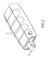
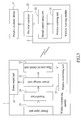
- the wireless transmitting module 1 includes a first outer casing 10, a power storage unit 11 disposed inside the first outer casing 10, a first control circuit unit 12 disposed inside the first outer casing 10 and electrically connected to the power storage unit 11, and a wireless transmitting unit 13 disposed inside the first outer casing 10 and electrically connected to the first control circuit unit 12 for generating electromagnetic fields or electromagnetic signals.
- the first outer casing 10 has a placing platform 103 for carrying or supporting the wireless receiving module 2 and a non-slip structure 104 opposite to the placing platform 103, and the placing platform 103 and the non-slip structure 104 are respectively disposed on two opposite surfaces of the first outer casing 10.
- the wireless transmitting module 1 further includes a transformer 14 disposed inside the first outer casing 10 and electrically connected to the power storage unit 11, a power input unit 15 electrically connected to the transformer 14, and at least one power output unit 16 electrically connected to the power storage unit 11.
- a transformer 14 disposed inside the first outer casing 10 and electrically connected to the power storage unit 11, a power input unit 15 electrically connected to the transformer 14, and at least one power output unit 16 electrically connected to the power storage unit 11.
- the power source can sequentially pass through the power transmission line W1, the power input unit 15 and the transformer 14 to charge up the power storage unit 11, thus the wireless transmitting module 1 can be used as a power supply.
- the transformer 14 can be omitted from the wireless transmitting module 1, so that the power input unit 15 can be electrically connected to the power storage unit 11 directly.
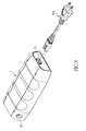
- the wireless receiving module 2 includes a second outer casing 20, a wireless receiving unit 21 disposed inside the second outer casing 20 for wirelessly receiving the electromagnetic fields generated by the wireless transmitting unit 13, a second control circuit unit 22 disposed inside the second outer casing 20 and electrically connected to the wireless receiving unit 21, and at least one electrical connector 23 exposed outside or from the second outer casing 20 and electrically connected between the second control circuit unit 22 and a portable electronic device P (such as a mobile phone). More precisely, the wireless receiving module 2 further includes a support unit 24 connected to the second outer casing 20 for supporting the at least one electrical connector 23.
- the support unit 24 has a support body 240 connected to the second outer casing 20 for fixing the height of the at least one electrical connector 23 relative to the second outer casing 20 and a pull ring 241 connected to the support body 240 and opposite to the at least one electrical connector 23, and the pull ring 241 is provided for the user to hold it.
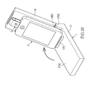
- the wireless transmitting module 1 when the wireless transmitting module 1 is overturned by 180 degrees, the wireless transmitting module 1 can be firmly placed on any plane through the non-slip structure 104. After inserting the at least one electrical connector 23 of the wireless receiving module 2 into the USB socket (not shown) of the portable electronic device P for electrically connecting the at least one electrical connector 23 with the portable electronic device P, the portable electronic device P can be placed on the placing platform 103 of the first outer casing 10 as shown in FIG. 6 .
- the transmitting coil 130 of the wireless transmitting unit 13 can generate an AC (alternating Current) electromagnetic field through the AC power source.
- the AC electromagnetic field generated from the transmitting coil 130 of the wireless transmitting unit 13 is wirelessly received by the receiving coil 210 of the wireless receiving unit 21, the AC electromagnetic field can be transformed into an electrical energy through the second control circuit unit 22, and then the electrical energy can be transmitted to the portable electronic device P to charge up the portable electronic device P through the at least one electrical connector 23.
- the wireless transmitting module 1 when the wireless transmitting module 1 and the wireless receiving module 2 are mated with each other to charge up the portable electronic device P, the wireless transmitting module 1 can be used as a power supply to charge up another portable electronic device (such as a notebook or another mobile phone, not shown) by matching the at least one power output unit 16 (such as a DC jack, a USB socket or any type of socket) and another power transmission line W1.
- another portable electronic device such as a notebook or another mobile phone, not shown
- the at least one power output unit 16 such as a DC jack, a USB socket or any type of socket
- the first outer casing 10 of the wireless transmitting module 1 has at least one first receiving space 101 corresponding to the second outer casing 20 and at least one second receiving space 102 corresponding to the at least one electrical connector 23, and both the at least one first receiving space 101 and the at least one second receiving space 102 are formed on the same lateral side of the first outer casing 10. More precisely, the second outer casing 20 has a first opening 1010 communicated with the at least one first receiving space 101 and a second opening 1020 communicated with the at least one second receiving space 102.
- the second outer casing 20 can be received inside the at least one first receiving space 101 of the first outer casing 10 through the at least one first opening 1010, and the at least one electrical connector 23 can be received inside the at least one second receiving space 102 of the first outer casing 10 through the at least one second opening 1020.
- the at least one first receiving space 101 and the at least one second receiving space 102 are separated from each other and not communicated with each other, and the first opening 1010 of the at least one first receiving space 101 and the second opening 1020 of the at least one second receiving space 102 are separated from each other and not communicated with each other.
- the first outer casing 10 has a first retaining structure 105 (such as a retaining groove) disposed inside the at least one first receiving space 101
- the second outer casing 20 has a second retaining structure 200 (such as a retaining block) corresponding to the first retaining structure 105.
- the first outer casing 10 and the at least one electrical connector 23 of the wireless receiving module 2 are respectively received inside the at least one first receiving space 101 and the at least one second receiving space 102 of the first outer casing 10, the first outer casing 10 and the at least one electrical connector 23 can be respectively retained inside the at least one first receiving space 101 and the at least one second receiving space 102 by retainably or slidably matching the first retaining structure 105 and the second retaining structure 200, for preventing the wireless receiving module 2 from being separated easily from the wireless transmitting module 1.
- the wireless transmitting module 1 further includes a base seat 17, and the first outer casing 10 is pivotally disposed on (or pivoted to) the base seat 17.
- the first outer casing 10 is pivotally disposed on (or pivoted to) the base seat 17.
- one of short sides 1000 of the first outer casing 10 is pivotally disposed on one of short sides 1700 of the base seat 17.
- one of the long sides 1001 of the first outer casing 10 is pivotally disposed on one of the long sides 1701 of the base seat 17.
- the portable electronic device P can be horizontally placed on the wireless transmitting module 1 and charged by matching the wireless transmitting module 1 and the wireless receiving module 2.
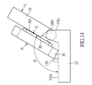
- the first outer casing 10 when the first outer casing 10 is upwardly rotated relative to the base seat 17 by a predetermined angle (shown as the arrow in FIG. 10 ), the first outer casing 10 is inclined by a predetermined acute angle ⁇ with respect to the base seat 17. Under this status, referring to FIG. 10 and FIG. 11 (or FIG. 13 and FIG. 14 ), when the first outer casing 10 is upwardly rotated relative to the base seat 17 by a predetermined angle (shown as the arrow in FIG. 10 ), the first outer casing 10 is inclined by a predetermined acute angle ⁇ with respect to the base seat 17. Under this status, referring to FIG.
- the portable electronic device P when the second outer casing 20 is disposed on the first outer casing 10 and inclined to the base seat 17, the portable electronic device P is disposed on the second outer casing 20 and inclined to the base seat 17.
- the portable electronic device P when the portable electronic device P is charging by matching the wireless transmitting module 1 and the wireless receiving module 2, the portable electronic device P can be obliquely disposed on the base seat 17 and leaned against the first outer casing 10 through the wireless receiving module 2, thus it is convenient for the user to watch the information provided by the display of the portable electronic device P.
- the base seat 17 has a positioning convex block 170 disposed on the top surface 1702 thereof, thus when the portable electronic device P is obliquely disposed on the base seat 17 and leaned against the first outer casing 10 through the wireless receiving module 2, the second outer casing 20 can be separated from the base seat 17 by a predetermined distance, and the bottom portion P1 of the portable electronic device P can be positioned between the positioning convex block 170 and the top surface 1702 of the base seat 17.
- this is merely an example and is not meant to limit the instant disclosure.
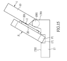
- the base seat 17 has a positioning concave groove 171 formed on the top surface 1702 thereof, thus when the portable electronic device P is obliquely disposed on the base seat 17 and leaned against the first outer casing 10 through the wireless receiving module 2, the second outer casing 20 can be separated from the base seat 17 by a predetermined distance, and the bottom portion P1 of the portable electronic device P can be directly positioned inside the positioning concave groove 171.
- this is merely an example and is not meant to limit the instant disclosure.
- the second outer casing 20 has a plurality of skidproof pads 201 disposed on the rear surface thereof for contacting the first outer casing 10, thus the portable electronic device P can be obliquely disposed on the base seat 17 and leaned against the first outer casing 10 through the skidproof pads 201 of the wireless receiving module 2 without using the positioning convex block 170 or the positioning concave groove 171.
- the second outer casing 20 is obliquely disposed on the first outer casing 10
- the portable electronic device P is obliquely disposed on the second outer casing 20, thus it is convenient for the user to watch the information provided by the display of the portable electronic device P.
- the wireless charging device can be applied to charge the inclined portable electronic device P as a result of the design of "the first outer casing 10 is pivotally disposed on the base seat 17" and "the first outer casing 10 is inclined by a predetermined acute angle with respect to the base seat 17".
- the second outer casing 20 is obliquely disposed on the first outer casing 10
- the portable electronic device P is obliquely disposed on the second outer casing 20, thus it is convenient for the user to watch the information provided by the display of the portable electronic device P.
Landscapes
- Engineering & Computer Science (AREA)
- Power Engineering (AREA)
- Computer Networks & Wireless Communication (AREA)
- Charge And Discharge Circuits For Batteries Or The Like (AREA)
- Telephone Set Structure (AREA)
Applications Claiming Priority (1)
| Application Number | Priority Date | Filing Date | Title |
|---|---|---|---|
| TW103212982U TWM491296U (zh) | 2014-07-21 | 2014-07-21 | 無線充電裝置 |
Publications (2)
| Publication Number | Publication Date |
|---|---|
| EP2985847A2 true EP2985847A2 (de) | 2016-02-17 |
| EP2985847A3 EP2985847A3 (de) | 2016-04-06 |
Family
ID=51753108
Family Applications (1)
| Application Number | Title | Priority Date | Filing Date |
|---|---|---|---|
| EP14189891.6A Withdrawn EP2985847A3 (de) | 2014-07-21 | 2014-10-22 | Drahtlose Ladevorrichtung |
Country Status (4)
| Country | Link |
|---|---|
| US (1) | US20160020626A1 (de) |
| EP (1) | EP2985847A3 (de) |
| CN (1) | CN204167924U (de) |
| TW (1) | TWM491296U (de) |
Cited By (2)
| Publication number | Priority date | Publication date | Assignee | Title |
|---|---|---|---|---|
| WO2020201456A1 (en) * | 2019-04-02 | 2020-10-08 | Ifpl Group Limited | Inductive charger |
| CN117276933A (zh) * | 2022-06-22 | 2023-12-22 | 通用电气航空系统有限责任公司 | 电子连接组件 |
Families Citing this family (5)
| Publication number | Priority date | Publication date | Assignee | Title |
|---|---|---|---|---|
| CN108591871A (zh) * | 2016-08-06 | 2018-09-28 | 胡玥 | 一种带有无线充电功能的led灯 |
| KR102561570B1 (ko) | 2016-10-06 | 2023-07-31 | 삼성전자주식회사 | 무선 충전을 제어하는 전자 장치 및 방법 |
| US11329506B2 (en) | 2019-02-15 | 2022-05-10 | Xentris Wireless, Llc | Modular wireless power bank system |
| CN110165747A (zh) * | 2019-06-13 | 2019-08-23 | 昆山联滔电子有限公司 | 具有收纳功能的充电装置 |
| CN212162931U (zh) * | 2019-10-21 | 2020-12-15 | 广东高普达集团股份有限公司 | 无线充电器 |
Family Cites Families (10)
| Publication number | Priority date | Publication date | Assignee | Title |
|---|---|---|---|---|
| US7352567B2 (en) * | 2005-08-09 | 2008-04-01 | Apple Inc. | Methods and apparatuses for docking a portable electronic device that has a planar like configuration and that operates in multiple orientations |
| US9130394B2 (en) * | 2009-02-05 | 2015-09-08 | Qualcomm Incorporated | Wireless power for charging devices |
| US8610398B2 (en) * | 2011-01-04 | 2013-12-17 | Primax Electronics Ltd. | Wireless charging receiver for portable electronic device |
| US8395353B2 (en) * | 2011-01-04 | 2013-03-12 | Primax Electronics, Ltd. | Wireless charging transmitter for portable electronic device |
| JP2012221854A (ja) * | 2011-04-12 | 2012-11-12 | Sanyo Electric Co Ltd | 出力コネクタを備えるバッテリパック |
| US20120319487A1 (en) * | 2011-06-16 | 2012-12-20 | Rakesh Shah | Integrated Battery Backup and Charging for Mobile Devices |
| US8729854B2 (en) * | 2011-10-18 | 2014-05-20 | Fu Da Tong Technology Co., Ltd. | Slot-type induction charger |
| DE102013226220A1 (de) * | 2012-12-21 | 2014-06-26 | Robert Bosch Gmbh | Induktionshandwerkzeugakkuvorrichtung |
| CN203233211U (zh) * | 2013-05-07 | 2013-10-09 | 吴锋强 | 一种无线充电的移动电源 |
| TWM467240U (zh) * | 2013-07-05 | 2013-12-01 | guo-shun Yang | 可平置及傾斜充電的無線充電發射裝置 |
-
2014
- 2014-07-21 TW TW103212982U patent/TWM491296U/zh not_active IP Right Cessation
- 2014-08-01 CN CN201420430878.4U patent/CN204167924U/zh not_active Expired - Fee Related
- 2014-10-03 US US14/506,129 patent/US20160020626A1/en not_active Abandoned
- 2014-10-22 EP EP14189891.6A patent/EP2985847A3/de not_active Withdrawn
Non-Patent Citations (1)
| Title |
|---|
| None |
Cited By (5)
| Publication number | Priority date | Publication date | Assignee | Title |
|---|---|---|---|---|
| WO2020201456A1 (en) * | 2019-04-02 | 2020-10-08 | Ifpl Group Limited | Inductive charger |
| GB2597011A (en) * | 2019-04-02 | 2022-01-12 | Ifpl Group Ltd | Inductive charger |
| CN117276933A (zh) * | 2022-06-22 | 2023-12-22 | 通用电气航空系统有限责任公司 | 电子连接组件 |
| EP4297544A1 (de) * | 2022-06-22 | 2023-12-27 | GE Aviation Systems LLC | Elektronische verbindungsanordnung |
| US12322916B2 (en) | 2022-06-22 | 2025-06-03 | Ge Aviation Systems Llc | Electronic connection assembly |
Also Published As
| Publication number | Publication date |
|---|---|
| US20160020626A1 (en) | 2016-01-21 |
| TWM491296U (zh) | 2014-12-01 |
| EP2985847A3 (de) | 2016-04-06 |
| CN204167924U (zh) | 2015-02-18 |
Similar Documents
| Publication | Publication Date | Title |
|---|---|---|
| EP2985847A2 (de) | Drahtlose Ladevorrichtung | |
| CN204131179U (zh) | 能平躺或成角度充电的无线充电座 | |
| US8699230B2 (en) | Combined type storage case for electronic device accessories | |
| JP3169916U (ja) | 両面充電式ワイヤレス充電スタンド | |
| CN102611169B (zh) | 可携式电子装置的无线充电传输装置 | |
| US9577451B2 (en) | Holder for portable electronic device | |
| CN103166287B (zh) | 移动电子终端设备的底座 | |
| US9325199B2 (en) | Wireless charging device | |
| US20230119496A1 (en) | Free voltage multi-charging device for battery | |
| CN201781331U (zh) | 具有无线充电的转接器 | |
| TWM397037U (en) | Three-in-one lithium battery structure of portable power bank, power capacity detection and charger | |
| CN211720289U (zh) | 移动电源 | |
| CN202721459U (zh) | 可携式无线充电装置 | |
| CN210576855U (zh) | 一种带ac插头及可换内置线的无线充移动电源 | |
| US20180219395A1 (en) | Collapsible battery charger (cbc) | |
| TWI495222B (zh) | 可攜式電子裝置之無線充電傳輸裝置 | |
| US20220271545A1 (en) | Combined storage case for electronic device accessories | |
| CN218897091U (zh) | 一种移动电源 | |
| TWM498994U (zh) | 背蓋結構 | |
| CN218940712U (zh) | 一种充电装置及移动电源组件 | |
| CN201696832U (zh) | 电子装置的置放结构 | |
| CN201430450Y (zh) | 多功能充电器 | |
| TWM480197U (zh) | 具有收納功能的無線充電裝置 | |
| CN209346764U (zh) | 用于料理机的主机、料理机及料理机组件 | |
| TWI479721B (zh) | 可攜式行動電源 |
Legal Events
| Date | Code | Title | Description |
|---|---|---|---|
| PUAI | Public reference made under article 153(3) epc to a published international application that has entered the european phase |
Free format text: ORIGINAL CODE: 0009012 |
|
| AK | Designated contracting states |
Kind code of ref document: A2 Designated state(s): AL AT BE BG CH CY CZ DE DK EE ES FI FR GB GR HR HU IE IS IT LI LT LU LV MC MK MT NL NO PL PT RO RS SE SI SK SM TR |
|
| AX | Request for extension of the european patent |
Extension state: BA ME |
|
| PUAL | Search report despatched |
Free format text: ORIGINAL CODE: 0009013 |
|
| AK | Designated contracting states |
Kind code of ref document: A3 Designated state(s): AL AT BE BG CH CY CZ DE DK EE ES FI FR GB GR HR HU IE IS IT LI LT LU LV MC MK MT NL NO PL PT RO RS SE SI SK SM TR |
|
| AX | Request for extension of the european patent |
Extension state: BA ME |
|
| RIC1 | Information provided on ipc code assigned before grant |
Ipc: H02J 5/00 20160101AFI20160304BHEP Ipc: H02J 7/00 20060101ALI20160304BHEP Ipc: H02J 50/80 20160101ALI20160304BHEP Ipc: H02J 7/02 20060101ALI20160304BHEP |
|
| STAA | Information on the status of an ep patent application or granted ep patent |
Free format text: STATUS: THE APPLICATION IS DEEMED TO BE WITHDRAWN |
|
| 18D | Application deemed to be withdrawn |
Effective date: 20161007 |