EP2986233B1 - Nadelskopisches instrument mit wiederverwendbarem griff und abnehmbarer nadelanordnung - Google Patents
Nadelskopisches instrument mit wiederverwendbarem griff und abnehmbarer nadelanordnung Download PDFInfo
- Publication number
- EP2986233B1 EP2986233B1 EP14786095.1A EP14786095A EP2986233B1 EP 2986233 B1 EP2986233 B1 EP 2986233B1 EP 14786095 A EP14786095 A EP 14786095A EP 2986233 B1 EP2986233 B1 EP 2986233B1
- Authority
- EP
- European Patent Office
- Prior art keywords
- assembly
- needle
- shaft
- handle assembly
- grasping
- Prior art date
- Legal status (The legal status is an assumption and is not a legal conclusion. Google has not performed a legal analysis and makes no representation as to the accuracy of the status listed.)
- Active
Links
Images







Classifications
-
- A—HUMAN NECESSITIES
- A61—MEDICAL OR VETERINARY SCIENCE; HYGIENE
- A61B—DIAGNOSIS; SURGERY; IDENTIFICATION
- A61B17/00—Surgical instruments, devices or methods
- A61B17/28—Surgical forceps
- A61B17/29—Forceps for use in minimally invasive surgery
-
- A—HUMAN NECESSITIES
- A61—MEDICAL OR VETERINARY SCIENCE; HYGIENE
- A61B—DIAGNOSIS; SURGERY; IDENTIFICATION
- A61B17/00—Surgical instruments, devices or methods
- A61B17/34—Trocars; Puncturing needles
- A61B17/3494—Trocars; Puncturing needles with safety means for protection against accidental cutting or pricking, e.g. limiting insertion depth, pressure sensors
- A61B17/3496—Protecting sleeves or inner probes; Retractable tips
-
- A—HUMAN NECESSITIES
- A61—MEDICAL OR VETERINARY SCIENCE; HYGIENE
- A61B—DIAGNOSIS; SURGERY; IDENTIFICATION
- A61B17/00—Surgical instruments, devices or methods
- A61B2017/0023—Surgical instruments, devices or methods disposable
-
- A—HUMAN NECESSITIES
- A61—MEDICAL OR VETERINARY SCIENCE; HYGIENE
- A61B—DIAGNOSIS; SURGERY; IDENTIFICATION
- A61B17/00—Surgical instruments, devices or methods
- A61B2017/0046—Surgical instruments, devices or methods with a releasable handle; with handle and operating part separable
-
- A—HUMAN NECESSITIES
- A61—MEDICAL OR VETERINARY SCIENCE; HYGIENE
- A61B—DIAGNOSIS; SURGERY; IDENTIFICATION
- A61B17/00—Surgical instruments, devices or methods
- A61B2017/00982—General structural features
- A61B2017/00991—Telescopic means
-
- A—HUMAN NECESSITIES
- A61—MEDICAL OR VETERINARY SCIENCE; HYGIENE
- A61B—DIAGNOSIS; SURGERY; IDENTIFICATION
- A61B17/00—Surgical instruments, devices or methods
- A61B17/28—Surgical forceps
- A61B17/29—Forceps for use in minimally invasive surgery
- A61B17/2909—Handles
- A61B2017/2912—Handles transmission of forces to actuating rod or piston
- A61B2017/2919—Handles transmission of forces to actuating rod or piston details of linkages or pivot points
Definitions
- the present invention relates to surgical instruments and methods of their assembly, and more particularly, to minimally invasive surgical instruments incorporating a needle and a working tool disposed within and configured to extend and retract from the needle tip.
- Minimally invasive surgery generally involves introducing an optical element (e.g., laparoscopic or endoscope) through a surgical or natural port in the body, advancing one or more surgical instruments through additional ports or through the endoscope, conducting the surgery with the surgical instruments, and withdrawing the instruments and scope from the body.
- an optical element e.g., laparoscopic or endoscope
- laparoscopic surgery (broadly defined herein to be any surgery where a port is made via a surgical incision, including but not limited to abdominal laparoscopy, arthroscopy, spinal laparoscopy, etc.), a port for a scope is typically made using a surgical trocar assembly.
- the trocar assembly often includes a port, a sharp pointed element (trocar) extending through and beyond the distal end of the port, and at least in the case of abdominal laparoscopy, a valve on the proximal portion of the port.
- a small incision is made in the skin at a desired location in the patient.
- the trocar assembly, with the trocar extending out of the port, is then forced through the incision, thereby widening the incision and permitting the port to extend through the incision, past any facie, and into the body (cavity).
- the trocar is then withdrawn, leaving the port in place.
- an insufflation element may be attached to the trocar port in order to insufflate the surgical site.
- An optical element may then be introduced through the trocar port. Additional ports are then typically made so that additional laparoscopic instruments may be introduced into the body.
- Trocar assemblies are manufactured in different sizes.
- Typical trocar port sizes include 5 mm, 10 mm, and 12 mm, which are sized to permit variously sized laparoscopic instruments to be introduced therethrough including, e.g., graspers, dissectors, staplers, scissors, suction/irrigators, clamps, forceps, biopsy forceps, etc.
- 5mm trocar ports are relatively small, in some circumstances where internal working space is limited (e.g., children), it is difficult to place multiple 5mm ports in the limited area.
- 5mm trocar ports tend to limit movement of instruments inside the abdominal cavity to a great extent.
- laparoscopic surgery has reduced the trauma associated with various surgical procedures and has concomitantly reduced recovery time from these surgeries, there always remains a desire in the art to further reduce the trauma to the patient.
- One area of trauma associated with laparoscopic surgery identified by the inventor hereof as being susceptible of reduction are the scars which result from the trocar ports used.
- three or more trocar incisions are made.
- four trocar incisions are typically made, with one incision for insufflating the abdomen and inserting the optical device, two incisions for trocar ports for inserting graspers therethrough, and a fourth port for passing a stapler therethrough.
- a second area of trauma associated with laparoscopic surgery relates to trauma resulting from the manipulation (e.g, angling) of the trocar ports required in order to conduct the surgery due to inexact placement.
- Angling of the port can cause tearing at the incision periphery. Such tearing can lead to extensive scar tissue and in general an extension of the incision area.
- inventive device includes a reusable handle assembly which can be actuated with various needle assemblies of varying diameters and end effectors.
- inventive device may have many different uses within one surgical procedure.
- the surgical assembly of the invention is a low cost, easy to manufacture, medical device which can be used, for example, during minimally invasive surgical procedures to reduce trauma to a patient.
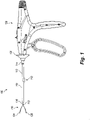
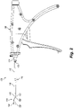
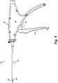
- a surgical device 100 which includes a disposable needle assembly 110 and two embodiments of a reusable handle assembly 150 operatively associated therewith.
- Figures 1 and 3 show one embodiment of the reusable handle assembly 150 while Figures 2 , 4 , and 5 show another embodiment of the reusable handle assembly 150.
- the reusable handle assembly 150 is preferably configured and adapted to receive the disposable needle assembly 110, manipulate it during a surgical procedure, and release it for disposal.
- the disposable needle assembly 110 is preferably configured and adapted to be advanced into the reusable handle assembly 150, set into position, and operated for one time use.
- the disposable needle assembly 110 is also preferably configured and adapted to prevent reprocessing thereof once used, and may be provided with a 2.4mm needle or a 5mm needle.
- the reusable handle assembly 150 is preferably configured and adapted to receive, operate, and release the disposable needle assembly 110 regardless of whether a 2.4mm needle is provided for insertion percutaneously under direct visualization without the use of a trocar, or whether a 5mm needle is provided for use with a trocar during laparoscopic procedures. In this manner, the surgical device 100 allows for improved management and control of the assemblies thereof, reduces costs to health care providers, and prevents unauthorized reprocessing and selling of needle assemblies without MLT certification.
- disposable needle assembly 110 includes an elongated needle member 112, a needle hub 114 which detachably couples and is longitudinally fixed to the handle assembly 150, and a grasping assembly 116 operatively associated with a lumen 113 defined by elongated needle member 112.
- Elongated needle member 112 and grasping assembly 116 are selectively longitudinally translatable relative to one another and relative to needle hub 114 and handle assembly 150 via user manipulation of handle assembly 150.
- Elongated needle member 112 includes a sharpened distal tip portion 118, a needle shaft 119 having an inner surface which defines lumen 113 through which grasping assembly 116 longitudinally translates. Needle shaft 119 extends through a lumen 120 defined by needle hub 114, and into the interior of the handle assembly 150 as shown in Figure 6 . Continuing with Figure 6 , needle shaft 119 of needle member 112 extends through proximal and distal portions 114a, 114b of needle hub 114, and couples to proximal member 130. Proximal member 130 has a proximal head 115 of enlarged diameter which interfaces to sliding shaft 122 of the handle assembly 150. As shown, sliding shaft 122 is coupled to a trigger 158 of handle assembly 150. In this manner, trigger 158 is retractable to distally longitudinally translate sliding shaft 122 of handle assembly 150 and proximal member 130 of needle member 112 relative to grasping assembly 116.
- grasping assembly 116 includes a pair of end effectors (e.g., upper and lower arms) 124, 126 coupled to or integrally formed with a shaft 128 having an outer surface profile corresponding to the inner surface of the needle shaft 119.
- Upper and lower arms 124, 126 are preferably biased radially outward from the longitudinal axis of shaft 128, but can also be provided as one or more hinged jaws or other surgical tools such as those described in the above referenced patents and publications.
- Shaft 128 extends through lumen 113 along the length of the needle shaft 119, through needle hub 114, and into the interior of the handle assembly 150 as shown in Figure 6 .
- Shaft 128 of grasping assembly 116 is coupled to a proximal member 130 having a proximal end 132.
- Proximal member 130 is selectively longitudinally translatable within the lumen 113 of elongated needle member 112, and within the sliding shaft 122 of handle assembly 150 via user manipulation of a retractable slide of the handle assembly 150 (further discussed below).
- the retractable slide of the handle assembly 150 interfaces to proximal end 132 to translate shaft 128 and arms 124, 126 of grasping assembly 116 relative to elongated needle member 112.
- Proximal member 130 preferably has a cross-section which defines an interference fit with interior surfaces of the lumen 113 of elongated needle member 112 to rotatably fix elongated needle member 112 to grasping assembly 116.
- the lumen 113 may define a rectangular cross section and proximal member 130 may also define a rectangular cross section along at least a portion thereof which can longitudinally translate within proximal member 130, yet which cannot rotate relative thereto.
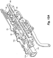
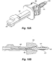
- Needle hub 114 also preferably defines lumen 120 in a manner which allows longitudinal translation of needle shaft 119 relative to needle hub 114, yet which rotatably fixes needle hub 114 to needle shaft 119. Certain embodiments of such rotational limits are shown in Figures 10 and 12A .
- such structure facilitates rotation of needle member 112, needle hub 114, and grasping assembly 116 together independent of handle assembly 150, as well as longitudinal advancement of the needle member 112 over the grasping assembly 116, all by user manipulation of handle assembly 150.
- handle assembly 150 includes a housing 152 for storing and protecting the components thereof, a rotation hub 154 for rotating the elongated needle member 112, needle hub 114, and grasping assembly 116, and a proximal handle member 156, a distal trigger 158, and a drive link 160 for actuating distal longitudinal translation of the elongated needle member 112 relative to the grasping assembly 116.
- Such distal translation causes the disposable assembly 110 to move from the open configuration shown in Figure 1 to the closed configuration shown in Figure 5 as the needle member 112 is forced over at least a portion of the arms 124, 126.
- the grasping assembly 116 may further be covered by the needle or sharpened distal tip portion 118 as shown in Figure 3 .
- Figures 1-5 also show the grasping assembly 116 in different stages of actuation.
- the grasping assembly has open arms 124, 126 compared to Figure 2 where arm 124 is open but arm 126 is semi-closed and compared to Figure 5 where arms 124, 126 are closed but the distal tip 118 of the needle has not been pushed over the grasping assembly 118 such that in use the grasping assembly 118 is grasping a material such as tissue, a blood vessel or organ.
- handle assembly 150 further includes a crank assembly 162 for coupling trigger 158 to sliding shaft 122 of handle assembly 150, and a primary return spring 164 for biasing sliding shaft 122 proximally and trigger 158 distally toward the configuration of Figure 2 in which the arms 124, 126 of the grasping assembly 116 are extended relative to the needle member 112 and open.
- Handle assembly 150 also includes an arm slide 166 for manipulating elongated needle member 112, a secondary return spring 168 for biasing arm slide 166 distally toward the position shown in Figure 7 (which corresponds to the configuration of Figure 2 ).
- Handle assembly 150 also includes a release lever 170 for allowing release of disposable needle assembly 110 from handle assembly 150, and a latch assembly for receiving, positioning, operating, and releasing elongated needle member 112 from handle assembly 150.
- the latch assembly includes latches 174a, 174b, 174c, and release bar 176, which, in conjunction with release lever 170, operate to vertically raise and lower latches 174a, 174b, 174c to receive and release the disposable assembly 110.
- the release lever does not need to move to receive a disposable assembly.
- latches 174a, 174b, 174c respectively couple to proximal end 132 of proximal member 130 of grasping assembly 116, proximal end 115 of proximal member 113 of elongated needle member 112, and an intermediary member 121 coupled to and disposed between shaft 119 and proximal member 113 as shown.
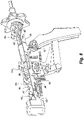
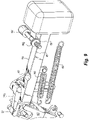
- Release bar 176 defines horizontal grooves 178, 180, 182 which receive respective pins 184, 186, 188 ( Figure 8 ) of latches 174a, 174b, 174c to allow longitudinal translation of the latches in their respective grooves.
- Release bar 176 also defines vertical grooves 190, 192 which receive pins 191, 193 connected to housing 152. Pins 191, 193 substantially constrain movement of release bar 176 to the vertical direction relative to housing 152, and also restrict the extent of such vertical movement as shown.
- assembly of one embodiment of the surgical device 100 occurs as follows.
- Proximal member 130 of disposable needle member 112 is advanced into an aperture (not shown) in rotation hub 154 and into the interior of the housing 152 via aperture 153.
- Proximal end 132 encounters latch 174c, which rotates clockwise (as sloped surface 175 is pushed upward by proximal end 132) to allow entry of proximal member 130.
- release bar 176 is biased upward by vertical spring 177, which biases latches 174a, 174b, 174c toward counter clockwise rotation toward their original position when they are rotated clockwise.
- Proximal end 132 is fed through sliding shaft 122 of housing assembly 150, and advanced proximately until it reaches distal end 155 of retraction slide 166, which is operatively disposed in a forward position as shown in Figure 6 .
- proximal end 132 reaches distal end 155 of retraction slide 166, it clicks into place between distal end 155 and latch 174a as latch 174a closes around the enlarged head thereof.
- proximal end 132 of proximal member 130 of grasping assembly 116 reaches distal end 155 of retraction slide 166
- the radially enlarged head 117 of proximal member 113 of elongated needle member 112 interfaces to sliding shaft 122 of handle assembly 150, and also snaps into place between latch member 174b and sliding shaft 122.
- both the inner grasping assembly 116 and outer needle member 112 are positioned and operatively coupled to handle assembly 150 for independent control thereof.
- FIG. 6 The assembled configuration of Figure 6 corresponds to that shown in Figure 5 , in which the arms 124, 126 of the grasping assembly 116 are exposed and act as an obturator relative to the distal tip 118 to help prevent accidental trauma with the distal tip 118.
- trigger 158 has been pulled back and ratcheted in place via ratchet 159 to keep arms 124, 126 in a closed position.
- the surgical device 100 could be shipped in this configuration with one disposable needle assembly 110 already assembled therein. Alternatively or additionally, the surgical device 100 could be shipped with a single handle assembly 150 and one or more separate disposable needle assemblies 110 separately contained in the same or different packaging.
- Button 194 (best shown in Figure 9 ) is depressed by a user (e.g., a surgeon), causing rim 194a to deploy from groove 195 defined in retraction slide 166 to ride along edge 181 of retraction slide 166.
- Retraction slide 166 may then be pulled proximally against the bias of spring 168 until rim 194a reaches secondary groove 197 and snaps therein. This motion pulls slide 166 to the retracted position of Fig. 4 , which directly pulls arms 124, 126 of grasping assembly 116 fully into needle member 112 to expose distal tip 118 as shown in Fig.
- Rotation hub 154 may be utilized to rotate grasping assembly 116 and needle member 112 as needed independent of housing assembly 150, and the entire assembly may additionally be manipulated by the surgeon as needed to establish a desired orientation of arms 124, 126 about target tissue in the patient.
- ratchet 159 is disengaged, and trigger 158 is pulled to distally advance sliding shaft 122, and thus needle member 112 over the grasping assembly 116 to close and clamp arms 124, 126 about the target tissue. It will be appreciated that arms/jaws 124, 126 remain in a fixed longitudinal position relative to the patient during closing thereof, which can be advantageous to the surgeon to avoid unwanted motion or displacement.
- release lever 170 ( Figures 6 , 8 ) is operated to vertically raise release bar 176, which vertically raises latches 174a, 174b, 174c to provide clearance for removal of disposable needle assembly 110 through aperture 153.
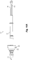
- Disposable assembly 110 ( Figure 16A ) is pulled distally through aperture 153 ( Figure 7 ) for removal and discarding thereof.
- a new disposable assembly can subsequently be used with the reusable handle assembly 150.
- the handle assembly 150 may be steam sterilized or sterilized through any other suitable and appropriate manner known in the art.
- the disposable needle assembly 110 includes a push button assembly 200 and associated structure which prevents longitudinal translation of grasping assembly 116 relative to needle member 112 when button 201 is operatively disposed in an unpressed radially outward configuration.
- push button 201 is configured and adapted to be radially translated from the radially outward position to a radially inward position.
- flanges 202, 204 interface to shaft 128 (e.g., via interference fit) of grasping assembly 116 to prevent distal longitudinal translation of shaft 128 relative to shaft 119 of elongated needle member 112.
- button 201 defines a cutout 206 situated to provide a passage for longitudinal translation of shaft 128 when button 201 is depressed into the radially inward position.
- Button 201 preferably extends into needle hub 114, and defines an arcuate outer surface 208 which is radially aligned with or radially inward of outer surface 123 of needle hub 114 when button 201 is depressed to the radially inward position.
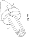
- side surface 211 of button 201 preferably forms an interference fit with inner surface 210 ( Figure 16A ) of needle hub 114 such that significant pressure is needed to depress button 201. In this manner, once depressed, button 201 becomes stuck in the depressed position and cannot be moved radially outward because all surfaces thereof are firmly wedged within needle hub 114.
- button assembly 200 prevents needle assembly 110 from accordion folding when inserted into reusable handle assembly 150 (e.g., prevents grasping assembly 116 and componets thereof from translating distally relative to elongated needle member 112 when disposable needle assembly 110 is inserted into handle assembly 150). It will also be appreciated that once disposable needle assembly 110 is inserted into handle assembly 150, button 201 may be depressed to allow distal translation of grasping assembly 116 to operate the device 100.
- Button assembly 200 also functions to help prevent unauthorized re-use, re-selling, or replication of disposable needle assembly 110 by virtue of the inability to longitudinally lock the components of the needle assembly 110 (e.g., for loading the needle assembly 110 into the handle assembly 150) once button 200 is pushed, and the inability to take apart disposable needle assembly 110.
- elongated needle 112 may be configured as one integrated piece of uniform diameter extending from distal tip 118 to proximal end 115
- grasping assembly 116 may similarly be configured as one integrated piece extending from arms 124, 126 to proximal end 132.
- one or two latches may be utilized instead of three, and structure different from the latches and sliding shaft disclosed above may be utilized to interface to elongated needle 112 and grasping assembly 116.
- a disposable needle assembly 310 which includes a conventional 5mm device.
- Disposable needle assembly 310 includes a shaft 319 configured to be inserted through a standard trocar, hub assembly 314 configured and adapted to be coupled and longitudinally fixed to housing assembly 150, and proximal inner shaft 330 which longitudinally translates within shaft 319 and hub assembly 314.
- inner shaft 330 contains a radially enlarged rim 335 which couples to sliding shaft 122 of housing assembly 150.
- trigger 158 of housing assembly 150 may be utilized to directly translate the inner rather than the outer components of the disposable assembly.
- shaft 319 is longitudinally fixed to hub assembly 314, and that only inner shaft 330 moves relative thereto.
- Button assembly 200 is preferably provided to disposable needle assembly 310 in order to prevent longitudinal translation of the components thereof during loading into housing assembly 150 as discussed above.
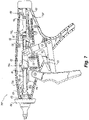
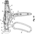
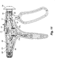
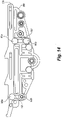
- FIG. 10 and 11 show two sides of a further embodiment of the handle assembly 150 of the present invention wherein the trigger motion of the trigger 158 when compressed causes a rotational motion of the crank assembly 162 which causes linear motion of the elongated needle member 112.
- the trigger 158 is of different configuration than that shown in Figures 6 and 7 .
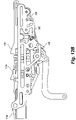
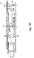
- trigger 158 is of an open trigger with movement limited by a trigger lock (shown in Figures 12A and 12B ).
- the trigger lock 340 includes a trigger lock link 346 and rotational lock such that when the button 201 is pushed inward by the user (e.g., surgeon) the trigger lock 340 locks in the trigger 158 in a depressed state with the grasping assembly 116 in a closed position.
- the handle assembly includes a cage comprised of a right cage 360 and left cage 361 which defines the inner workings of the handle assembly 150.
- handle assembly 150 further includes a primary return spring 164 for biasing sliding trigger 158 distally toward the configuration of Figure 1 in which the arms 124, 126 of the grasping assembly 116 are extended relative to the needle member 112 and open.
- Handle assembly 150 also includes an arm slide 166 for manipulating elongated needle member 112.
- Handle assembly 150 also includes a release switch 175 and release spring 171 for allowing release of disposable assembly 110 from handle assembly 150 and a latch assembly for receiving, positioning, operating, and releasing elongated needle member 112 from the guide box 179 within handle assembly 150.
- the guide box 179 is configured to match the configuration of the proximal member 130 of the disposable needle assembly 110 such as, for example, both the guide box 179 and proximal member 130 being configured in the shape of a rectangle or square or circle or oval or any other corresponding geometric shape.
- the latch assembly includes latches 174d and 174e ,which are found on right cage 360, and release bar 176, which, in conjunction with release spring 171, operate to vertically raise and lower latches 174d and 174e to receive and release the disposable assembly 110.
- Release bar 176 defines horizontal grooves 178 and 180 which receive respective pins 184 and 186 of latches 174d and 174d to allow longitudinal translation of the latches in their respective grooves.
- release bar 176 on right cage 360 also defines vertical grooves 190, 192 which receive pins 191a, 191b, 193a and 193b connected to housing 152. Pins 191a, 191 b, 193a and 193b substantially constrain movement of release bar 176 to the vertical direction relative to housing 152, and also restrict the extent of such vertical movement as shown.
- the handle assembly 150 includes a ratchet mechanism so as to prevent trigger and needle return throughout the full jaw closure stroke.
- the ratchet mechanism has audible and tactile clicks during actuation.
- the ratchet mechanism may have a number of lock positions and in one embodiment has a minimum of nine (9) lock positions throughout the full jaw closure stroke.
- the final ratchet position may correspond with the fully closed jaw safe position.
- a ratchet 159 is shown as activated by a ratchet switch 157.
- the ratchet switch 157 allows the ratchet mechanism to be turned on and off to disengaged the ratchet and allow free opening of the jaws upon manual release of the trigger 158.
- the ratchet switch 157 is found on both sides of the handle assembly 150 and may be actuated by the thumb of the user.
- the up switch position corresponds with the ratchet mode, the down position corresponds to the free mode.
- the switch shaft 161 is connected to the switch spring level 163 activated by the switch link 165 and switch spring 167.
- the ratchet spring 169 is connected to the ratchet switch 157.
- a switch spring 167 drives the switch to its final ratchet or free positions to prevent the switch from residing in an intermediate position. Switch actuation will have an audible and tactile click when in use.
- a temporary ratchet release trigger resides forward of the main trigger and is to be actuated by the index finger. The temporary release trigger allows the ratchet to be released when it is squeezed when the device is in the ratchet mode. It will have a spring return and will reengage the ratchet when it is released.
- FIG. 150 Another feature of this embodiment of the handle assembly 150 of the present invention is the rotational hub 154.
- a rotation detent spring 151 which provides an audio cue to the user (e.g., surgeon) that the needle member 112 is moving such that there are clicks generated via the spring 151.
- proximal end 132 encounters latch 174d, such latch rotates clockwise (as sloped surface 175 is pushed upward by proximal end 132) to allow entry of proximal member 130.
- release bar 176 is biased upward by vertical spring 177, which biases latches 174d and 174e toward counter clockwise rotation toward their original position when they are rotated clockwise.
- Proximal end 132 is fed through sliding shaft 122 of housing assembly 150, and advanced proximately until it reaches distal end 155 of retraction slide 166, which is operatively disposed in a forward position (not shown in Figures 10 and 11 ).
- proximal end 132 reaches distal end 155 of retraction slide 166, it clicks into place between distal end 155 and latch 174d as latch 174d closes around the enlarged head thereof.
- proximal end 132 of proximal member 130 of grasping assembly 116 reaches distal end 155 of retraction slide 166
- the radially enlarged head 117 of proximal member 113 of needle member 112 interfaces to sliding shaft 122 of handle assembly 150, and also snaps into place between latch member 174e and sliding shaft 122.
- both the inner grasping assembly 116 and outer needle member 112 are positioned and operatively coupled to handle assembly 150 for independent control thereof.
- button 194 is depressed by a user (e.g., a surgeon), causing as shown in Figure 21, push button spring 205 to compress allowing sliding shaft 122 to deploy.
- Retraction slide 166 may then be pulled proximally against the bias of spring 168 and this motion pulls arms 124, 126 of grasping assembly 116 fully into needle member 112 to expose distal tip 118 as shown in Figures 3 and 4 .
- the device is armed, and the distal tip 118 is advanced into the patient to a surgical site.
- button 194 is depressed, and spring 168 pulls slide 166 back to the forward position and to the advanced open configuration of the arms 124, 126 in Figures 1 and 2 .
- Rotation hub 154 may be utilized to rotate grasping assembly 116 and elongated needle member 112 as needed independent of housing assembly 150, and the entire assembly may additionally be manipulated by the surgeon as needed to establish a desired orientation of arms 124, 126 about target tissue in the patient.
- ratchet 159 is disengaged, and trigger 158 is pulled to distally advance sliding shaft 122, and thus elongated needle member 112 over the grasping assembly 116 to close and clamp arms 124, 126 about the target tissue.
- the grasping arms 124, 126 remain in a fixed longitudinal position relative to the patient during closing thereof, which can be advantageous to the surgeon to avoid unwanted motion or displacement.
- the arm slide 166 may only be actuated when the trigger 158 is fully closed and each mechanism is separate.
- release switch 175 is operated to vertically raise release bar 176, which vertically raises latches 174d and 174e to provide clearance for removal of disposable needle assembly 110 through aperture 153.
- a new disposable assembly can subsequently be used with the reusable handle assembly 150.
- Other end effectors of the disposable assembly may be used such as scissors, grabbers, clasps, staplers, needle holders, cauterizers and other known end effectors. If graspers are chosen the graspers may include configurations of babcock, alligator, clutch and bowel style jaws and other known variants.
- the handle assembly 150 may be steam sterilized or sterilized through any other suitable and appropriate manner known in the art.
- a typical electrosurgical treatment instrument is capable of treating tissue with the use of heat produced by electrical energy while cutting, shearing, grasping, or contacting the tissue. Such instruments are used to carry out treatments, such as incision, coagulation, and the like.
- Such a procedure instrument or device would be equipped with an active electrode and an inactive, so-called neutral electrode.
- the neutral electrode is electrically connected to a large area of the skin of the patient, for example, to the thigh or the upper arm.
- the surgical instrument interface may further comprise an electrical connector for connecting the conductor to an external electrosurgical generator.
- Electrical energy may be supplied to the surgical instrument by a conventional electrosurgical which the user (e.g., surgeon) may activate via a foot switch electrically connected to the electrosurgical generator, causing the generator to supply electrical energy through a power cord and the connector to the instrument.
- a high frequency AC or RF current may be employed, with the voltage being dependent on the type and degree of treatment desired. Voltages may range up to at least 12,000V in some cases, with about 3000V being a typical value, e.g., for coagulation.
- a monopolar arm 400 includes a contact post 420 having a cage 410 of a plurality of spiral loops.
- the contact post 420 is connected to an electrical source as described above.
- the monopolar arm 400 further includes a monopolar arm slide 430 which has an aperture 460 for insertion of the disposable needle assembly 110 or any other disposable assembly capable of activation via electrical energy.
- the monopolar arm 400 further includes monopolar spring 440 and contact plunger 450 so that when the disposable needle assembly 110 is inserted into the aperture 460 it exerts a force on the contact plunger 450 which compresses contact spring 440 and the electrical energy is transferred via contact post 420 to the disposable needle assembly 110.
- the present invention allows for a single reusable handle assembly 150 into which many types of disposable assemblies may be inserted, locked, actuated and then released for disposable. It will be appreciated that separation of the needle and handle assemblies 110, 150 described above will also allow the needle assemblies to be melted down and recycled, and the handles to be sterilized and reused. Additionally, it will be appreciated that the access surface area provided by a 5 mm trocar is approximately 24.6mm 2 whereas that provided by the 2.4 mm needle is approximately 4.5 mm 2 , which represents an 82% reduction in access surface area, meaning no stitching or scars, less pain, and a quicker recovery for the patient. Further, the device may be inserted percutaneously under direct visualization by the surgeon without the use of a trocar, resulting in a shorter surgery with less tissue trauma and scars.
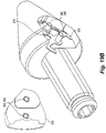
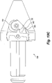
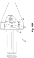
- the needle assembly includes a lock hub assembly 500 which includes a cap 510 covering an internal lock spring 520 attached to a lock pivot 530 which has an upper distal end 532 and lower distal end 534 each of which is capable of protruding from the cap 510 and is capable of moving in one direction.
- the lock pivot 530 is actuated when the needle assembly 110 is inserted into and then released from the handle assembly 150. Upon insertion of the needle assembly 110 into the handle assembly 150 the lock pivot 530 rotates such the upper distal end 522 which was protruding from the cap 510 now resides within the cap 510.
- the lock pivot 530 Upon release from the handle assembly 150 the lock pivot 530 further rotates but is stopped by the cap 510 actuating a lock bar 540 which locks into a latch 550 within the cap 510.
- the lower distal end 534 of the lock pivot 530 thus protrudes from the cap 510. In this position the disposable needle assembly 110 cannot be reused resulting in a safety feature.
- the cap 510 is attached to the lock hub assembly 500 via at least one, preferably two, apertures 562, 564 in the cap 510 which attach to a corresponding male member 566, 568 located within the lock hub assembly 500.
- the inventive surgical device includes a trigger 158 design in which the pistol grip style has a fixed palm grip and pivoting finger actuated trigger such that the trigger may wrap around the middle and ring finger for use with smaller hands whereas the surgeon with larger hands may grip the outer surface of the wrap around trigger 158.
- the trigger 158 finger indents may be provided.
- the trigger 158 in use may thus be used by either right handed surgeons and left handed surgeons. Further, in use the inventive device is capable of being operated single-handedly, with the exception of loading and releasing the disposable assemblies.
- the inventive device has the advantages of an unloaded handle having a trigger and arming slide locked in position ready to accept new assemblies such as a needle assembly having different end effectors.
- the disposable assembly may only be released in a safe position with for instance if using a grasper, fully closed jaws it is anticipated that such a release switch mechanism to be useful for a minimum of 1000 cycles.
- Further safety features include the arm slide 166 extending from the back of the handle assembly 150 which must be pulled forward with the user's for instance thumb and index finger by a gripping surface to retract for instance the grasping arms or jaws completely into the disposable needle member 112 and fully expose the needle tip 118. In use the user's nominal arming stroke may be about .620. Upon complete arming the arm slide 166 actuation a latch mechanism which automatically locks the device in the armed position. A red visible indicator shows that the needle assembly 110 is armed and that the sharp needle tip 118 is exposed. A button located toward the rear of the left side of the handle assembly 150 is to be depressed to spring return the needle assembly 110 to the safe position with the needle tip 188 retracted within the elongated needle member 112.
- a nominal return spring load at the armed position is capable of driving the grasper arms 124, 126 out of the needle assembly 110 and is 1.09 Kg (2.4 pounds) of weight or force. It is anticipated that such an arming mechanism to be useful for a minimum of 1000 cycles.
- the rotation hub 154 which may include with light resistance to prevent an inadvertent rotation of the grasping assembly 116.
- the rotation hub 154 has a tactile resistance and audible clicks heard by the user to indicate the rotations.
- There is a range of continuous rotation in both directions of the rotation hub 154 allowing the user ambidextrous operation of all functions during surgery except there is a lock during insertion and release of the assembly.
- the rotation lock is actuated during trigger actuation so as to allow rotational manipulation of grasped tissue without the need to manually restrain the rotation hub 154.
- Yet another safety feature of the present invention includes the trigger 158 actuation which requires force to overcome the primary return spring 164 to advance needle tip 118 over axially fixed graspers 124, 126.
- the nominal needle actuation stroke from the safe position to the end effector fully open position is .690.
- a complete spring return of trigger and needle is required for the needle assembly 110 with a range of nominal return spring load at the safe position of about 0.59 Kg (1.3 pounds). It is anticipated that such a trigger 158 actuation mechanism may be useful for a minimum of 7500 cycles.
- a further safety feature of the present invention includes a ratchet switch 157 or ratchet mechanism 159 which may prevent the trigger 158 and needle tip 118 return throughout the full actuation and closing of the graspers 124, 126.
- the ratchet 159 in use may have audible and tactile clicks during actuation.
- the ratchet 159 may have a minimum of for instance a range of about three (3) to about ten (10) lock positions throughout the full graspers 124, 126 closure stroke.
- the final ratchet 159 position may correspond with the fully closed grasping assembly 116 in a safe position.
- a ratchet switch 157 will allow the ratchet 159 to be turned on and off to disengaged the ratchet 159 and allow free opening of the grasping assembly 116, or any other assembly with other end effectors, upon manual release of the trigger 158 by the user.
- the ratchet switch 157 may reside on both sides of the handle assembly 150 and thus may be actuated with the thumb of the user.
- the up switch position of the ratchet switch 157 corresponds with the ratchet mode while the down position corresponds to the free mode.
- a ratchet spring 169 will drive the ratchet switch 157 to either its final ratchet position or free position so as to prevent the ratchet switch 157 from residing in an intermediate position.
- Such ratchet switch 157 actuation may have an audible and tactile click as a further safety feature for the user.
- a temporary ratchet release trigger may reside forward of the main trigger 158 and may be actuated by the index finger of the user. Such a temporary release trigger will allow the ratchet 159 to be released when the release trigger is squeezed during the time in use when the device is in the ratchet 159 mode.
- Such an embodiment may have a spring return and will reengage the ratchet 159 when the temporary release trigger is released.
- the life of the handle assembly 150 may exceed more than 350 surgical procedures and corresponding autoclave cycles.
- the snap-in insertion and release of loading units causes minimal abrasion, and is anticipated to be useful for a minimum of 1,000 cycles.
- the handle assembly 150 has the advantage of being configured to receive multiple needle assemblies of varying diameters.
- the handle assembly may receive and lock a needle assembly having a 5 mm diameter, a 10 mm diameter or other variants.
- the handle assembly 150 has a universal use with many disposable needle assemblies and even other assemblies without needles.
Landscapes
- Health & Medical Sciences (AREA)
- Surgery (AREA)
- Life Sciences & Earth Sciences (AREA)
- Medical Informatics (AREA)
- Nuclear Medicine, Radiotherapy & Molecular Imaging (AREA)
- Engineering & Computer Science (AREA)
- Biomedical Technology (AREA)
- Heart & Thoracic Surgery (AREA)
- Molecular Biology (AREA)
- Animal Behavior & Ethology (AREA)
- General Health & Medical Sciences (AREA)
- Public Health (AREA)
- Veterinary Medicine (AREA)
- Ophthalmology & Optometry (AREA)
- Pathology (AREA)
- Surgical Instruments (AREA)
Claims (9)
- Vorrichtung, um eine Einweg-Nadelbaugruppe eines chirurgischen Geräts einzusetzen, umfassend:eine Einweg-Nadelbaugruppe (110), eine wiederverwendbare Griffbaugruppe (150) und einen Rückzugsschieber (166),wobei die Einweg-Nadelbaugruppe (110) dafür konfiguriert ist, in die wiederverwendbare Griffbaugruppe (150) eingeführt zu werden, wobei die Einweg-Nadelbaugruppe (110) ein Nadelelement, das eine geschärfte distale Spitze aufweist, einen Nadelschaft mit einer Innenfläche, die ein Nadelschaftlumen definiert, und ein Nadelverbindungsstück, das lösbar an die Griffbaugruppe (150) gekoppelt ist und ein Nadelverbindungsstücklumen definiert, einschließt,wobei der Nadelschaft über einen Gleitschaft (122) in dem Inneren der Griffbaugruppe (150) durch das Nadelverbindungsstücklumen und in ein Inneres der Griffbaugruppe (150) ausfahrbar ist, wobei die Einweg-Nadelbaugruppe (110) ebenfalls eine Greifbaugruppe (116) aufweist, die sich in Längsrichtung durch das Nadelschaftlumen verschiebt, wobei die Greifbaugruppe (116) Arme aufweist, die mit einem Armschaft gekoppelt oder integral geformt sind, wobei die wiederverwendbare Griffbaugruppe (150) eine Kurbelbaugruppe (162) zum Koppeln eines Auslösers an den Gleitschaft (122) zum Betätigen des Nadelschafts (119), eine primäre Rückstellfeder zum Vorspannen des Gleitschafts (122) in Proximalrichtung und des Auslösers in Distalrichtung einschließt, um so die Arme der Greifbaugruppe (116) auf eine Weise auszufahren, welche die Arme an einer Position, jenseits der geschärften distalen Spitze des Nadelelements, voneinander weg spannt,wobei die Einweg-Nadelbaugruppe (110) und die Greifbaugruppe (116) dafür konfiguriert und angeordnet sind, selektiv mit der wiederverwendbaren Griffbaugruppe (150) im Verhältnis zueinander und im Verhältnis zu dem Nadelverbindungsstück und im Verhältnis zu der wiederverwendbaren Griffbaugruppe (150) manipuliert zu werden, undwobei der Rückzugsschieber (166) dafür konfiguriert und angeordnet ist, manipuliert zu werden, um selektiv ein proximales Element (130) innerhalb des Nadelschaftlumens und innerhalb des Gleitschafts (122) in Längsrichtung zu verschieben, wobei sich der Rückzugsschieber (166) mit einem proximalen Ende des proximalen Elements (130) verknüpft, um den Armschaft und die Arme der Greifbaugruppe (116) im Verhältnis zu dem Nadelelement zu verschieben, wobei das proximale Element (130) dafür konfiguriert und angeordnet ist, eine Presspassung mit einer Innenfläche des Nadelschaftlumens und einer Innenfläche des Nadelverbindungsstücklumens zu definieren, um das Nadelelement drehbar an der Greifbaugruppe (116) zu fixieren.
- Vorrichtung nach Anspruch 1, wobei der Rückzugsschieber (166) einen Rand aufweist, der eine primäre Rille des Rückzugsschiebers (166) veranlasst, entlang einer Kante des Rückzugsschiebers zu gleiten, wobei der Rückzugsschieber dafür konfiguriert ist, sich gegen eine Vorspannung einer Feder zurückzuziehen, bis der Rand eine sekundäre Rille des Rückzugsschiebers erreicht, wo der Rand in die sekundäre Rille einrastet, wobei die Arme der Greifbaugruppe (116) dafür konfiguriert und angeordnet sind, als Reaktion auf das Zurückziehen, vollständig in das Nadelelement der Einweg-Nadelbaugruppe gezogen zu werden, um eine distale Spitze des Nadelelements freizulegen, und als Reaktion darauf, dass die Arme der Greifbaugruppe (116) vollständig in das Nadelelement gezogen werden, sich die distale Spitze des Nadelelements bis zu einer Operationsstelle vorschiebt.
- Vorrichtung nach Anspruch 2, die ferner eine Druckknopfbaugruppe umfasst, die dafür konfiguriert und angeordnet ist, in Radialrichtung zwischen in Radialrichtung inneren und äußeren Positionen verschoben zu werden, um so eine Längsverschiebung des Armschafts der Greifbaugruppe im Verhältnis zu dem Nadelelement zu verhindern, wenn die Druckknopfbaugruppe wirksam in der in Radialrichtung äußeren Position angeordnet ist, die ebenfalls einen nicht-gedrückten Zustand darstellt, durch Veranlassen, dass sich Flansche mit dem Armschaft der Greifbaugruppe verknüpfen.
- Vorrichtung nach Anspruch 3, wobei das Nadelverbindungsstück lösbar gekoppelt ist und in Längsrichtung an der Griffbaugruppe (150) fixiert ist, wobei die Druckknopfbaugruppe einen Druckknopf einschließt, der als Reaktion darauf, dass der Druckknopf in die in Radialrichtung innere Position niedergedrückt wird, in seiner Position stecken bleibt, so dass der Druckknopf nicht in Radialrichtung nach außen bewegt werden kann, weil Oberflächen des Druckknopfs innerhalb des Nadelverbindungsstücks verkeilt werden, von einer Presspassung, die zwischen einer Seitenfläche des Druckknopfs und einer Innenfläche des Nadelverbindungsstücks entsteht.
- Verfahren zum Zusammensetzen einer Einweg-Nadelbaugruppe (110) eines chirurgischen Geräts nach Anspruch 1, wobei das Verfahren Folgendes umfasst:Einführen einer Einweg-Nadelbaugruppe (110) in eine wiederverwendbare Griffbaugruppe (150), wobei die Einweg-Nadelbaugruppe (110) ein Nadelelement, das eine geschärfte distale Spitze aufweist, einen Nadelschaft mit einer Innenfläche, die ein Nadelschaftlumen definiert, und ein Nadelverbindungsstück, das lösbar an die Griffbaugruppe (150) gekoppelt ist und ein Nadelverbindungsstücklumen definiert, einschließt, wobei der Nadelschaft über einen Gleitschaft (122) in dem Inneren der Griffbaugruppe (150) durch das Nadelverbindungsstücklumen und in ein Inneres der Griffbaugruppe (150) ausfahrbar ist, wobei die Einweg-Nadelbaugruppe (110) ebenfalls eine Greifbaugruppe (116) aufweist, die sich in Längsrichtung durch das Nadelschaftlumen verschiebt, wobei die Greifbaugruppe (116) Arme aufweist, die mit einem Armschaft gekoppelt oder integral geformt sind, wobei die wiederverwendbare Griffbaugruppe (150) eine Kurbelbaugruppe zum Koppeln eines Auslösers an den Gleitschaft (122) zum Betätigen des Nadelschafts (119), eine primäre Rückstellfeder zum Vorspannen des Gleitschafts (122) in Proximalrichtung und des Auslösers in Distalrichtung einschließt, um so die Arme der Greifbaugruppe (116) auf eine Weise auszufahren, welche die Arme an einer Position, jenseits der geschärften distalen Spitze des Nadelelements, voneinander weg spannt,selektives Manipulieren der Einweg-Nadelbaugruppe (110) und der Greifbaugruppe (116) mit der wiederverwendbaren Griffbaugruppe (150) im Verhältnis zueinander und im Verhältnis zu dem Nadelverbindungsstück und im Verhältnis zu der wiederverwendbaren Griffbaugruppe (150) undManipulieren eines Rückzugsschiebers (166), um selektiv ein proximales Element innerhalb des Nadelschaftlumens und innerhalb des Gleitschafts (122) in Längsrichtung zu verschieben, wobei sich der Rückzugsschieber (166) mit einem proximalen Ende des proximalen Elements verknüpft, um den Armschaft und die Arme der Greifbaugruppe (116) im Verhältnis zu dem Nadelelement zu verschieben, wobei das proximale Element dafür konfiguriert und angeordnet ist, eine Presspassung mit einer Innenfläche des Nadelschaftlumens und einer Innenfläche des Nadelverbindungsstücklumens zu definieren, um das Nadelelement drehbar an der Greifbaugruppe (116) zu fixieren.
- Verfahren nach Anspruch 5, das ferner Folgendes umfasst:Verhindern, dass sich die Greifbaugruppe (116) in Distalrichtung im Verhältnis zu der Einweg-Nadelbaugruppe (110) verschiebt, wenn das Einführen der Einweg-Nadelbaugruppe (110) in die Griffbaugruppe (150) stattfindet, und,nach dem Schritt des Einführens, Niederdrücken einer Knopfbaugruppe, um zu ermöglichen, dass die distale Verschiebung einer Greifbaugruppe (116) erfolgt.
- Verfahren nach Anspruch 5, wobei das Niederdrücken der Knopfbaugruppe ein Arretieren von Bestandteilen der Nadelbaugruppe (110) in Längsrichtung verhindert.
- Verfahren nach Anspruch 5, wobei das Nadelelement einen Schaft aufweist, der sich durch proximale und distale Abschnitte des Nadelverbindungsstücks erstreckt und an ein proximales Element koppelt, das einen proximalen Kopf mit vergrößertem Durchmesser aufweist, der sich mit dem Gleitschaft (122) der Griffbaugruppe (150) verknüpft, wobei der Gleitschaft (122) auf eine Weise an einen Auslöser der Griffbaugruppe (150) gekoppelt ist, die es ermöglicht, dass sich der Auslöser zurückzieht, um so den Gleitschaft der Griffbaugruppe (150) und das proximale Element des Nadelelements in Distal- und in Längsrichtung im Verhältnis zu der Greifbaugruppe (116) zu verschieben.
- Verfahren nach Anspruch 5, wobei die Griffbaugruppe (150) ferner eine Kurbelbaugruppe zum Koppeln eines Auslösers an den Gleitschaft (122) der Griffbaugruppe (150) und eine primäre Rückstellfeder zum Vorspannen des Gleitschafts (122) in Proximalrichtung und des Auslösers in Distalrichtung einschließt, so dass die Arme der Greifbaugruppe (116) im Verhältnis zu dem Nadelelement ausgefahren werden und öffnen.
Applications Claiming Priority (2)
| Application Number | Priority Date | Filing Date | Title |
|---|---|---|---|
| US201361812691P | 2013-04-16 | 2013-04-16 | |
| PCT/US2014/034397 WO2014172477A2 (en) | 2013-04-16 | 2014-04-16 | Needlescopic instrument with reusable handle and detachable needle assembly |
Publications (3)
| Publication Number | Publication Date |
|---|---|
| EP2986233A2 EP2986233A2 (de) | 2016-02-24 |
| EP2986233A4 EP2986233A4 (de) | 2016-11-23 |
| EP2986233B1 true EP2986233B1 (de) | 2022-06-15 |
Family
ID=51731979
Family Applications (1)
| Application Number | Title | Priority Date | Filing Date |
|---|---|---|---|
| EP14786095.1A Active EP2986233B1 (de) | 2013-04-16 | 2014-04-16 | Nadelskopisches instrument mit wiederverwendbarem griff und abnehmbarer nadelanordnung |
Country Status (8)
| Country | Link |
|---|---|
| US (2) | US10537347B2 (de) |
| EP (1) | EP2986233B1 (de) |
| JP (1) | JP6267784B2 (de) |
| KR (1) | KR101792377B1 (de) |
| CN (1) | CN105377150B (de) |
| AU (2) | AU2014253930B2 (de) |
| CA (1) | CA2909648C (de) |
| WO (1) | WO2014172477A2 (de) |
Families Citing this family (24)
| Publication number | Priority date | Publication date | Assignee | Title |
|---|---|---|---|---|
| US9743987B2 (en) | 2013-03-14 | 2017-08-29 | Board Of Regents Of The University Of Nebraska | Methods, systems, and devices relating to robotic surgical devices, end effectors, and controllers |
| CN105377150B (zh) | 2013-04-16 | 2017-12-05 | 泰利福医疗公司 | 带有可重复使用的手柄和可拆卸的针组件的针式腹腔镜器械 |
| US10856901B2 (en) | 2013-09-18 | 2020-12-08 | Teleflex Medical Incorporated | Exchanger surgical access port assembly and methods of use |
| JP6400682B2 (ja) | 2014-07-15 | 2018-10-03 | テレフレックス メディカル インコーポレイテッド | 交換式外科用アクセスポート組立体 |
| US10188777B2 (en) | 2015-08-20 | 2019-01-29 | Aurastem Llc | Liposuction device and system and use thereof |
| CN108348261B (zh) | 2015-11-10 | 2021-03-16 | 柯惠有限合伙公司 | 可重复使用的内窥镜外科手术施夹器 |
| KR101783225B1 (ko) * | 2016-02-26 | 2017-09-29 | 주식회사 현주인테크 | 탄력적 이물림 구조를 갖는 분리형 내시경용 와이어 연결유닛 |
| WO2018098319A1 (en) | 2016-11-22 | 2018-05-31 | Board Of Regents Of The University Of Nebraska | Improved gross positioning device and related systems and methods |
| WO2018112199A1 (en) * | 2016-12-14 | 2018-06-21 | Virtual Incision Corporation | Releasable attachment device for coupling to medical devices and related systems and methods |
| EP3614930B1 (de) | 2017-04-28 | 2025-04-23 | Aurastem LLC | Mikro-lipo-nadelvorrichtungen |
| CN108420506B (zh) * | 2018-03-21 | 2023-11-24 | 汕头大学 | 一种可冲洗吸引和快速更换导管的腹腔钳 |
| CN112089458B (zh) * | 2019-05-30 | 2025-11-04 | 香港大学深圳医院 | 分体式手术缝合器 |
| WO2021183024A1 (en) | 2020-03-10 | 2021-09-16 | Vigmed Ab | Needle shielding device |
| JP2023532977A (ja) | 2020-07-06 | 2023-08-01 | バーチャル インシジョン コーポレイション | 外科用ロボット位置決めシステム並びに関連する装置及び方法 |
| US11986199B2 (en) * | 2020-07-16 | 2024-05-21 | EndoGear, LLC | Grasping device for independent tissue manipulation during gastrointestinal endoscopic procedures and methods of use |
| CN111956875B (zh) * | 2020-08-26 | 2023-06-09 | 重庆尚业医疗器械有限公司 | 一种手动式防堵吸引管 |
| CN112274201B (zh) * | 2020-10-15 | 2021-07-23 | 苏州贝诺医疗器械有限公司 | 一种腹腔镜手术用缝合辅助器械 |
| CN113116431A (zh) * | 2021-04-14 | 2021-07-16 | 宁德市闽东医院 | 一种腹腔镜下疝气手术专用针 |
| CN114027920B (zh) * | 2021-12-17 | 2025-01-21 | 重庆医科大学附属口腔医院 | 一种便于取放的显微血管夹组件及其使用方法 |
| CN115363679B (zh) * | 2022-08-30 | 2025-11-25 | 杭州康基医疗器械有限公司 | 应用于连发施夹钳的分布进给机构 |
| CN116712144B (zh) * | 2023-06-09 | 2023-12-22 | 杭州伯柯曼生物科技有限公司 | 一种缝合植入物激发装置 |
| CN118319406A (zh) * | 2024-05-09 | 2024-07-12 | 苏州英途康医疗科技有限公司 | 柄部组件及其外科手术器械 |
| CN119454191B (zh) * | 2025-01-09 | 2025-04-01 | 北京天星医疗股份有限公司 | 医用缝合器 |
| CN120570671B (zh) * | 2025-08-05 | 2025-09-30 | 惠凯医疗科技(苏州)有限公司 | 一种热蒸汽消融排气针推送机构及应用其的消融设备 |
Family Cites Families (57)
| Publication number | Priority date | Publication date | Assignee | Title |
|---|---|---|---|---|
| JPS58133348U (ja) | 1982-03-03 | 1983-09-08 | メデイキツト株式会社 | カテ−テル |
| US4655750A (en) | 1985-11-22 | 1987-04-07 | Manresa, Inc. | Closed system catheter with guide wire |
| JPH0215159A (ja) | 1988-07-01 | 1990-01-18 | Mitsubishi Metal Corp | 表面被覆サーメット製切削工具の製造法 |
| US5201742A (en) | 1991-04-16 | 1993-04-13 | Hasson Harrith M | Support jig for a surgical instrument |
| US5658272A (en) | 1992-09-15 | 1997-08-19 | Hasson; Harrith M. | Surgical instrument support and method of using the same |
| US5282800A (en) | 1992-09-18 | 1994-02-01 | Edward Weck, Inc. | Surgical instrument |
| US5413561A (en) | 1993-05-13 | 1995-05-09 | Cathco, Inc. | Guiding catheter with sealing cap system for reducing blood loss when inserting guiding catheters |
| US5425376A (en) | 1993-09-08 | 1995-06-20 | Sofamor Danek Properties, Inc. | Method and apparatus for obtaining a biopsy sample |
| US5456673A (en) | 1994-03-23 | 1995-10-10 | Stryker Corporation | Locking cannula for endoscopic surgery |
| US5454790A (en) | 1994-05-09 | 1995-10-03 | Innerdyne, Inc. | Method and apparatus for catheterization access |
| US5505710A (en) | 1994-08-22 | 1996-04-09 | C. R. Bard, Inc. | Telescoping probe |
| US5626597A (en) * | 1995-02-21 | 1997-05-06 | United States Surgical Corporation | Percutaneous introducer |
| WO1997014457A1 (en) | 1995-10-18 | 1997-04-24 | Stouder Albert E Jr | Adjustable length cannula and trocar |
| US5868714A (en) | 1996-09-16 | 1999-02-09 | Endoscopic Concepts, Inc. | Trocar reducer system |
| US6159224A (en) | 1996-11-27 | 2000-12-12 | Yoon; Inbae | Multiple needle suturing instrument and method |
| US5759188A (en) * | 1996-11-27 | 1998-06-02 | Yoon; Inbae | Suturing instrument with rotatably mounted needle driver and catcher |
| US6197002B1 (en) | 1997-12-10 | 2001-03-06 | Phillips Plastics Corporation | Laparoscopic tool and method |
| US20030130693A1 (en) | 1999-05-18 | 2003-07-10 | Levin John M. | Laparoscopic/thorascopic insertion caps |
| US6224569B1 (en) | 1999-09-24 | 2001-05-01 | Becton, Dickinson And Company | Compact needle point shield |
| US6336914B1 (en) | 2000-01-13 | 2002-01-08 | Gillespie, Iii Richard D. | Releasable interlock assembly having axial and rotational engagement |
| EP1269925B1 (de) | 2001-06-19 | 2003-12-17 | Karl Storz GmbH & Co. KG | Zugangskanüle für endoskopische Operationen, insbesondere für die Arthroskopie |
| US20050059934A1 (en) | 2003-04-25 | 2005-03-17 | Thomas Wenchell | Surgical access apparatus |
| US7150749B2 (en) | 2003-06-13 | 2006-12-19 | Sherwood Services Ag | Vessel sealer and divider having elongated knife stroke and safety cutting mechanism |
| US7479150B2 (en) | 2003-09-19 | 2009-01-20 | Tyco Healthcare Group Lp | Trocar insertion apparatus |
| AU2004216609B2 (en) | 2003-09-30 | 2010-08-12 | Ethicon Endo-Surgery, Inc. | Rotational latching system for a trocar |
| US7329233B2 (en) | 2004-10-05 | 2008-02-12 | Tyco Healthcare Group Lp | Surgical system for laparoscopic surgery |
| US8113548B2 (en) | 2005-06-30 | 2012-02-14 | Ti Group Automotive Systems, Llc | Quick connector for high pressure applications |
| US20070093755A1 (en) | 2005-09-23 | 2007-04-26 | Koos David R | Cannula handle and storage system |
| US8430851B2 (en) | 2005-10-14 | 2013-04-30 | Applied Medical Resources Corporation | Surgical access port |
| US8080004B2 (en) * | 2005-10-26 | 2011-12-20 | Earl Downey | Laparoscopic surgical instrument |
| US7766937B2 (en) | 2006-03-13 | 2010-08-03 | Mini-Lap Technologies, Inc. | Minimally invasive surgical assembly and methods |
| US8313507B2 (en) | 2006-03-13 | 2012-11-20 | Mini-Lap Technologies, Inc. | Minimally invasive rake retractor and method for using same |
| US8133255B2 (en) | 2006-03-13 | 2012-03-13 | Mini-Lap Technologies, Inc. | Minimally invasive surgical assembly and methods |
| US9492187B2 (en) | 2006-03-13 | 2016-11-15 | Teleflex Medical Incorporated | Minimally invasive surgical assembly and methods |
| US9486238B2 (en) | 2006-03-13 | 2016-11-08 | Teleflex Medical Incorporated | Minimally invasive surgical clamps, assemblies and methods |
| US8230863B2 (en) | 2006-05-30 | 2012-07-31 | Mini-Lap Technologies, Inc. | Platform for fixing surgical instruments during surgery |
| US20070282170A1 (en) | 2006-05-30 | 2007-12-06 | Sundaram Ravikumar | Rake Retractor and Needle Assembly for Minimally Invasive Surgical Applications |
| US20080215078A1 (en) | 2007-01-31 | 2008-09-04 | Bennett Michael D | Surgical blade and trocar system |
| JP5105939B2 (ja) | 2007-04-06 | 2012-12-26 | 株式会社八光 | 医療用挿入ガイド器具 |
| US20090247900A1 (en) | 2008-03-25 | 2009-10-01 | Brian Zimmer | Push button adjustable spacer |
| US8956351B2 (en) | 2008-04-09 | 2015-02-17 | Teleflex Medical Incorporated | Minimally invasive surgical needle and cauterizing assembly and methods |
| US8636686B2 (en) | 2008-04-28 | 2014-01-28 | Ethicon Endo-Surgery, Inc. | Surgical access device |
| JP5464872B2 (ja) | 2009-03-06 | 2014-04-09 | 株式会社トップ | 鉗子 |
| IT1395219B1 (it) | 2009-05-19 | 2012-09-05 | Ab Medica Spa | Otturatore per trocar e relativo trocar. |
| US9326757B2 (en) | 2009-12-31 | 2016-05-03 | Teleflex Medical Incorporated | Surgical instruments for laparoscopic aspiration and retraction |
| US20110196205A1 (en) | 2010-02-05 | 2011-08-11 | Tyco Healthcare Group Lp | Surgical portal locking system |
| US8783542B2 (en) | 2010-09-30 | 2014-07-22 | Ethicon Endo-Surgery, Inc. | Fasteners supported by a fastener cartridge support |
| JP5782267B2 (ja) | 2011-02-16 | 2015-09-24 | 株式会社トップ | トロカーの外套管部 |
| US20120277576A1 (en) | 2011-04-26 | 2012-11-01 | Chun Kee Lui | Echogenic infusion port catheter |
| JP2013106771A (ja) | 2011-11-21 | 2013-06-06 | Olympus Corp | 医療用処置具および神経刺激電極留置システム |
| JP5999415B2 (ja) | 2012-06-01 | 2016-09-28 | 株式会社ジェイ・エム・エス | 留置針装置 |
| US10058343B2 (en) * | 2013-03-14 | 2018-08-28 | Covidien Lp | Systems for performing endoscopic procedures |
| KR102013539B1 (ko) | 2013-04-16 | 2019-08-22 | 텔리플렉스 메디컬 인코포레이티드 | 최소 절개 수술 조립체 및 방법 |
| CN105377150B (zh) | 2013-04-16 | 2017-12-05 | 泰利福医疗公司 | 带有可重复使用的手柄和可拆卸的针组件的针式腹腔镜器械 |
| JP6400682B2 (ja) | 2014-07-15 | 2018-10-03 | テレフレックス メディカル インコーポレイテッド | 交換式外科用アクセスポート組立体 |
| WO2016022789A1 (en) | 2014-08-07 | 2016-02-11 | Teleflex Medical Incorporated | Surgical instrument electrodes and methods of use |
| CN106572883A (zh) | 2014-08-13 | 2017-04-19 | 泰利福医疗公司 | 外科手术器械的电极及使用方法 |
-
2014
- 2014-04-16 CN CN201480034271.7A patent/CN105377150B/zh active Active
- 2014-04-16 KR KR1020157032316A patent/KR101792377B1/ko active Active
- 2014-04-16 EP EP14786095.1A patent/EP2986233B1/de active Active
- 2014-04-16 JP JP2016509075A patent/JP6267784B2/ja active Active
- 2014-04-16 WO PCT/US2014/034397 patent/WO2014172477A2/en not_active Ceased
- 2014-04-16 CA CA2909648A patent/CA2909648C/en active Active
- 2014-04-16 US US14/784,886 patent/US10537347B2/en active Active
- 2014-04-16 AU AU2014253930A patent/AU2014253930B2/en active Active
-
2017
- 2017-08-30 AU AU2017221786A patent/AU2017221786B2/en active Active
-
2020
- 2020-01-20 US US16/747,113 patent/US11627975B2/en active Active
Also Published As
| Publication number | Publication date |
|---|---|
| JP6267784B2 (ja) | 2018-01-24 |
| AU2017221786B2 (en) | 2018-07-05 |
| AU2014253930A1 (en) | 2015-11-12 |
| CA2909648C (en) | 2019-02-26 |
| KR20160075382A (ko) | 2016-06-29 |
| US10537347B2 (en) | 2020-01-21 |
| WO2014172477A3 (en) | 2015-01-08 |
| CA2909648A1 (en) | 2014-10-23 |
| CN105377150A (zh) | 2016-03-02 |
| KR101792377B1 (ko) | 2017-10-31 |
| US11627975B2 (en) | 2023-04-18 |
| CN105377150B (zh) | 2017-12-05 |
| AU2017221786A1 (en) | 2017-09-21 |
| JP2016525897A (ja) | 2016-09-01 |
| EP2986233A2 (de) | 2016-02-24 |
| AU2014253930B2 (en) | 2017-06-01 |
| US20200197035A1 (en) | 2020-06-25 |
| WO2014172477A2 (en) | 2014-10-23 |
| EP2986233A4 (de) | 2016-11-23 |
| US20160074055A1 (en) | 2016-03-17 |
Similar Documents
| Publication | Publication Date | Title |
|---|---|---|
| US11627975B2 (en) | Needlescopic instrument with reusable handle and detachable needle assembly | |
| EP2986239B1 (de) | Minimal invasive chirurgische baugruppe | |
| US5984939A (en) | Multifunctional grasping instrument with cutting member and operating channel for use in endoscopic and non-endoscopic procedures | |
| EP0920280B1 (de) | An fingerspitzen angebrachtes instrument für minimal-invasiven chirurgie | |
| US20130053877A1 (en) | Multiple Function Surgical Instrument | |
| EP3174484B1 (de) | Nadelskopischer scheren-endeffektor | |
| US20160175029A1 (en) | Tissue sealing and cutting instrument with locking features | |
| EP2983598B1 (de) | Minimal invasive chirurgische vorrichtungen | |
| US20140088638A1 (en) | Detachable End Effector with Lateral Lock | |
| US11596431B2 (en) | Apparatus with deployable probe and blade and methods of use |
Legal Events
| Date | Code | Title | Description |
|---|---|---|---|
| PUAI | Public reference made under article 153(3) epc to a published international application that has entered the european phase |
Free format text: ORIGINAL CODE: 0009012 |
|
| 17P | Request for examination filed |
Effective date: 20151113 |
|
| AK | Designated contracting states |
Kind code of ref document: A2 Designated state(s): AL AT BE BG CH CY CZ DE DK EE ES FI FR GB GR HR HU IE IS IT LI LT LU LV MC MK MT NL NO PL PT RO RS SE SI SK SM TR |
|
| AX | Request for extension of the european patent |
Extension state: BA ME |
|
| DAX | Request for extension of the european patent (deleted) | ||
| A4 | Supplementary search report drawn up and despatched |
Effective date: 20161025 |
|
| RIC1 | Information provided on ipc code assigned before grant |
Ipc: A61B 17/04 20060101AFI20161019BHEP |
|
| STAA | Information on the status of an ep patent application or granted ep patent |
Free format text: STATUS: REQUEST FOR EXAMINATION WAS MADE |
|
| STAA | Information on the status of an ep patent application or granted ep patent |
Free format text: STATUS: EXAMINATION IS IN PROGRESS |
|
| 17Q | First examination report despatched |
Effective date: 20201014 |
|
| GRAP | Despatch of communication of intention to grant a patent |
Free format text: ORIGINAL CODE: EPIDOSNIGR1 |
|
| STAA | Information on the status of an ep patent application or granted ep patent |
Free format text: STATUS: GRANT OF PATENT IS INTENDED |
|
| INTG | Intention to grant announced |
Effective date: 20220107 |
|
| GRAS | Grant fee paid |
Free format text: ORIGINAL CODE: EPIDOSNIGR3 |
|
| GRAA | (expected) grant |
Free format text: ORIGINAL CODE: 0009210 |
|
| STAA | Information on the status of an ep patent application or granted ep patent |
Free format text: STATUS: THE PATENT HAS BEEN GRANTED |
|
| AK | Designated contracting states |
Kind code of ref document: B1 Designated state(s): AL AT BE BG CH CY CZ DE DK EE ES FI FR GB GR HR HU IE IS IT LI LT LU LV MC MK MT NL NO PL PT RO RS SE SI SK SM TR |
|
| REG | Reference to a national code |
Ref country code: CH Ref legal event code: EP Ref country code: GB Ref legal event code: FG4D |
|
| REG | Reference to a national code |
Ref country code: IE Ref legal event code: FG4D |
|
| REG | Reference to a national code |
Ref country code: DE Ref legal event code: R096 Ref document number: 602014084034 Country of ref document: DE |
|
| REG | Reference to a national code |
Ref country code: AT Ref legal event code: REF Ref document number: 1497905 Country of ref document: AT Kind code of ref document: T Effective date: 20220715 |
|
| REG | Reference to a national code |
Ref country code: LT Ref legal event code: MG9D |
|
| REG | Reference to a national code |
Ref country code: NL Ref legal event code: MP Effective date: 20220615 |
|
| PG25 | Lapsed in a contracting state [announced via postgrant information from national office to epo] |
Ref country code: SE Free format text: LAPSE BECAUSE OF FAILURE TO SUBMIT A TRANSLATION OF THE DESCRIPTION OR TO PAY THE FEE WITHIN THE PRESCRIBED TIME-LIMIT Effective date: 20220615 Ref country code: NO Free format text: LAPSE BECAUSE OF FAILURE TO SUBMIT A TRANSLATION OF THE DESCRIPTION OR TO PAY THE FEE WITHIN THE PRESCRIBED TIME-LIMIT Effective date: 20220915 Ref country code: LT Free format text: LAPSE BECAUSE OF FAILURE TO SUBMIT A TRANSLATION OF THE DESCRIPTION OR TO PAY THE FEE WITHIN THE PRESCRIBED TIME-LIMIT Effective date: 20220615 Ref country code: HR Free format text: LAPSE BECAUSE OF FAILURE TO SUBMIT A TRANSLATION OF THE DESCRIPTION OR TO PAY THE FEE WITHIN THE PRESCRIBED TIME-LIMIT Effective date: 20220615 Ref country code: GR Free format text: LAPSE BECAUSE OF FAILURE TO SUBMIT A TRANSLATION OF THE DESCRIPTION OR TO PAY THE FEE WITHIN THE PRESCRIBED TIME-LIMIT Effective date: 20220916 Ref country code: FI Free format text: LAPSE BECAUSE OF FAILURE TO SUBMIT A TRANSLATION OF THE DESCRIPTION OR TO PAY THE FEE WITHIN THE PRESCRIBED TIME-LIMIT Effective date: 20220615 Ref country code: BG Free format text: LAPSE BECAUSE OF FAILURE TO SUBMIT A TRANSLATION OF THE DESCRIPTION OR TO PAY THE FEE WITHIN THE PRESCRIBED TIME-LIMIT Effective date: 20220915 |
|
| REG | Reference to a national code |
Ref country code: AT Ref legal event code: MK05 Ref document number: 1497905 Country of ref document: AT Kind code of ref document: T Effective date: 20220615 |
|
| PG25 | Lapsed in a contracting state [announced via postgrant information from national office to epo] |
Ref country code: RS Free format text: LAPSE BECAUSE OF FAILURE TO SUBMIT A TRANSLATION OF THE DESCRIPTION OR TO PAY THE FEE WITHIN THE PRESCRIBED TIME-LIMIT Effective date: 20220615 Ref country code: LV Free format text: LAPSE BECAUSE OF FAILURE TO SUBMIT A TRANSLATION OF THE DESCRIPTION OR TO PAY THE FEE WITHIN THE PRESCRIBED TIME-LIMIT Effective date: 20220615 |
|
| PG25 | Lapsed in a contracting state [announced via postgrant information from national office to epo] |
Ref country code: NL Free format text: LAPSE BECAUSE OF FAILURE TO SUBMIT A TRANSLATION OF THE DESCRIPTION OR TO PAY THE FEE WITHIN THE PRESCRIBED TIME-LIMIT Effective date: 20220615 |
|
| PG25 | Lapsed in a contracting state [announced via postgrant information from national office to epo] |
Ref country code: SM Free format text: LAPSE BECAUSE OF FAILURE TO SUBMIT A TRANSLATION OF THE DESCRIPTION OR TO PAY THE FEE WITHIN THE PRESCRIBED TIME-LIMIT Effective date: 20220615 Ref country code: SK Free format text: LAPSE BECAUSE OF FAILURE TO SUBMIT A TRANSLATION OF THE DESCRIPTION OR TO PAY THE FEE WITHIN THE PRESCRIBED TIME-LIMIT Effective date: 20220615 Ref country code: RO Free format text: LAPSE BECAUSE OF FAILURE TO SUBMIT A TRANSLATION OF THE DESCRIPTION OR TO PAY THE FEE WITHIN THE PRESCRIBED TIME-LIMIT Effective date: 20220615 Ref country code: PT Free format text: LAPSE BECAUSE OF FAILURE TO SUBMIT A TRANSLATION OF THE DESCRIPTION OR TO PAY THE FEE WITHIN THE PRESCRIBED TIME-LIMIT Effective date: 20221017 Ref country code: ES Free format text: LAPSE BECAUSE OF FAILURE TO SUBMIT A TRANSLATION OF THE DESCRIPTION OR TO PAY THE FEE WITHIN THE PRESCRIBED TIME-LIMIT Effective date: 20220615 Ref country code: EE Free format text: LAPSE BECAUSE OF FAILURE TO SUBMIT A TRANSLATION OF THE DESCRIPTION OR TO PAY THE FEE WITHIN THE PRESCRIBED TIME-LIMIT Effective date: 20220615 Ref country code: CZ Free format text: LAPSE BECAUSE OF FAILURE TO SUBMIT A TRANSLATION OF THE DESCRIPTION OR TO PAY THE FEE WITHIN THE PRESCRIBED TIME-LIMIT Effective date: 20220615 Ref country code: AT Free format text: LAPSE BECAUSE OF FAILURE TO SUBMIT A TRANSLATION OF THE DESCRIPTION OR TO PAY THE FEE WITHIN THE PRESCRIBED TIME-LIMIT Effective date: 20220615 |
|
| PG25 | Lapsed in a contracting state [announced via postgrant information from national office to epo] |
Ref country code: PL Free format text: LAPSE BECAUSE OF FAILURE TO SUBMIT A TRANSLATION OF THE DESCRIPTION OR TO PAY THE FEE WITHIN THE PRESCRIBED TIME-LIMIT Effective date: 20220615 Ref country code: IS Free format text: LAPSE BECAUSE OF FAILURE TO SUBMIT A TRANSLATION OF THE DESCRIPTION OR TO PAY THE FEE WITHIN THE PRESCRIBED TIME-LIMIT Effective date: 20221015 |
|
| REG | Reference to a national code |
Ref country code: DE Ref legal event code: R097 Ref document number: 602014084034 Country of ref document: DE |
|
| PG25 | Lapsed in a contracting state [announced via postgrant information from national office to epo] |
Ref country code: AL Free format text: LAPSE BECAUSE OF FAILURE TO SUBMIT A TRANSLATION OF THE DESCRIPTION OR TO PAY THE FEE WITHIN THE PRESCRIBED TIME-LIMIT Effective date: 20220615 |
|
| PLBE | No opposition filed within time limit |
Free format text: ORIGINAL CODE: 0009261 |
|
| STAA | Information on the status of an ep patent application or granted ep patent |
Free format text: STATUS: NO OPPOSITION FILED WITHIN TIME LIMIT |
|
| PG25 | Lapsed in a contracting state [announced via postgrant information from national office to epo] |
Ref country code: DK Free format text: LAPSE BECAUSE OF FAILURE TO SUBMIT A TRANSLATION OF THE DESCRIPTION OR TO PAY THE FEE WITHIN THE PRESCRIBED TIME-LIMIT Effective date: 20220615 |
|
| 26N | No opposition filed |
Effective date: 20230316 |
|
| PG25 | Lapsed in a contracting state [announced via postgrant information from national office to epo] |
Ref country code: SI Free format text: LAPSE BECAUSE OF FAILURE TO SUBMIT A TRANSLATION OF THE DESCRIPTION OR TO PAY THE FEE WITHIN THE PRESCRIBED TIME-LIMIT Effective date: 20220615 |
|
| REG | Reference to a national code |
Ref country code: CH Ref legal event code: PL |
|
| PG25 | Lapsed in a contracting state [announced via postgrant information from national office to epo] |
Ref country code: LU Free format text: LAPSE BECAUSE OF NON-PAYMENT OF DUE FEES Effective date: 20230416 |
|
| REG | Reference to a national code |
Ref country code: BE Ref legal event code: MM Effective date: 20230430 |
|
| PG25 | Lapsed in a contracting state [announced via postgrant information from national office to epo] |
Ref country code: MC Free format text: LAPSE BECAUSE OF FAILURE TO SUBMIT A TRANSLATION OF THE DESCRIPTION OR TO PAY THE FEE WITHIN THE PRESCRIBED TIME-LIMIT Effective date: 20220615 |
|
| PG25 | Lapsed in a contracting state [announced via postgrant information from national office to epo] |
Ref country code: MC Free format text: LAPSE BECAUSE OF FAILURE TO SUBMIT A TRANSLATION OF THE DESCRIPTION OR TO PAY THE FEE WITHIN THE PRESCRIBED TIME-LIMIT Effective date: 20220615 Ref country code: LI Free format text: LAPSE BECAUSE OF NON-PAYMENT OF DUE FEES Effective date: 20230430 Ref country code: IT Free format text: LAPSE BECAUSE OF FAILURE TO SUBMIT A TRANSLATION OF THE DESCRIPTION OR TO PAY THE FEE WITHIN THE PRESCRIBED TIME-LIMIT Effective date: 20220615 Ref country code: CH Free format text: LAPSE BECAUSE OF NON-PAYMENT OF DUE FEES Effective date: 20230430 |
|
| REG | Reference to a national code |
Ref country code: IE Ref legal event code: MM4A |
|
| PG25 | Lapsed in a contracting state [announced via postgrant information from national office to epo] |
Ref country code: BE Free format text: LAPSE BECAUSE OF NON-PAYMENT OF DUE FEES Effective date: 20230430 |
|
| PG25 | Lapsed in a contracting state [announced via postgrant information from national office to epo] |
Ref country code: IE Free format text: LAPSE BECAUSE OF NON-PAYMENT OF DUE FEES Effective date: 20230416 |
|
| PG25 | Lapsed in a contracting state [announced via postgrant information from national office to epo] |
Ref country code: IE Free format text: LAPSE BECAUSE OF NON-PAYMENT OF DUE FEES Effective date: 20230416 |
|
| PG25 | Lapsed in a contracting state [announced via postgrant information from national office to epo] |
Ref country code: BG Free format text: LAPSE BECAUSE OF FAILURE TO SUBMIT A TRANSLATION OF THE DESCRIPTION OR TO PAY THE FEE WITHIN THE PRESCRIBED TIME-LIMIT Effective date: 20220615 |
|
| PG25 | Lapsed in a contracting state [announced via postgrant information from national office to epo] |
Ref country code: BG Free format text: LAPSE BECAUSE OF FAILURE TO SUBMIT A TRANSLATION OF THE DESCRIPTION OR TO PAY THE FEE WITHIN THE PRESCRIBED TIME-LIMIT Effective date: 20220615 |
|
| PGFP | Annual fee paid to national office [announced via postgrant information from national office to epo] |
Ref country code: DE Payment date: 20250429 Year of fee payment: 12 |
|
| PGFP | Annual fee paid to national office [announced via postgrant information from national office to epo] |
Ref country code: GB Payment date: 20250428 Year of fee payment: 12 |
|
| PGFP | Annual fee paid to national office [announced via postgrant information from national office to epo] |
Ref country code: FR Payment date: 20250425 Year of fee payment: 12 |
|
| PG25 | Lapsed in a contracting state [announced via postgrant information from national office to epo] |
Ref country code: CY Free format text: LAPSE BECAUSE OF FAILURE TO SUBMIT A TRANSLATION OF THE DESCRIPTION OR TO PAY THE FEE WITHIN THE PRESCRIBED TIME-LIMIT; INVALID AB INITIO Effective date: 20140416 |
|
| PG25 | Lapsed in a contracting state [announced via postgrant information from national office to epo] |
Ref country code: HU Free format text: LAPSE BECAUSE OF FAILURE TO SUBMIT A TRANSLATION OF THE DESCRIPTION OR TO PAY THE FEE WITHIN THE PRESCRIBED TIME-LIMIT; INVALID AB INITIO Effective date: 20140416 |
|
| PG25 | Lapsed in a contracting state [announced via postgrant information from national office to epo] |
Ref country code: TR Free format text: LAPSE BECAUSE OF FAILURE TO SUBMIT A TRANSLATION OF THE DESCRIPTION OR TO PAY THE FEE WITHIN THE PRESCRIBED TIME-LIMIT Effective date: 20220615 |