EP2986244B1 - Dispositif de traitement rf fractionné de la peau - Google Patents
Dispositif de traitement rf fractionné de la peau Download PDFInfo
- Publication number
- EP2986244B1 EP2986244B1 EP14784768.5A EP14784768A EP2986244B1 EP 2986244 B1 EP2986244 B1 EP 2986244B1 EP 14784768 A EP14784768 A EP 14784768A EP 2986244 B1 EP2986244 B1 EP 2986244B1
- Authority
- EP
- European Patent Office
- Prior art keywords
- skin
- electrode
- range
- electrodes
- energy
- Prior art date
- Legal status (The legal status is an assumption and is not a legal conclusion. Google has not performed a legal analysis and makes no representation as to the accuracy of the status listed.)
- Active
Links
Images




Classifications
-
- A—HUMAN NECESSITIES
- A61—MEDICAL OR VETERINARY SCIENCE; HYGIENE
- A61B—DIAGNOSIS; SURGERY; IDENTIFICATION
- A61B18/00—Surgical instruments, devices or methods for transferring non-mechanical forms of energy to or from the body
- A61B18/04—Surgical instruments, devices or methods for transferring non-mechanical forms of energy to or from the body by heating
- A61B18/12—Surgical instruments, devices or methods for transferring non-mechanical forms of energy to or from the body by heating by passing a current through the tissue to be heated, e.g. high-frequency current
- A61B18/14—Probes or electrodes therefor
- A61B18/1477—Needle-like probes
-
- A—HUMAN NECESSITIES
- A61—MEDICAL OR VETERINARY SCIENCE; HYGIENE
- A61B—DIAGNOSIS; SURGERY; IDENTIFICATION
- A61B18/00—Surgical instruments, devices or methods for transferring non-mechanical forms of energy to or from the body
- A61B2018/00005—Cooling or heating of the probe or tissue immediately surrounding the probe
- A61B2018/00011—Cooling or heating of the probe or tissue immediately surrounding the probe with fluids
-
- A—HUMAN NECESSITIES
- A61—MEDICAL OR VETERINARY SCIENCE; HYGIENE
- A61B—DIAGNOSIS; SURGERY; IDENTIFICATION
- A61B18/00—Surgical instruments, devices or methods for transferring non-mechanical forms of energy to or from the body
- A61B2018/00005—Cooling or heating of the probe or tissue immediately surrounding the probe
- A61B2018/00011—Cooling or heating of the probe or tissue immediately surrounding the probe with fluids
- A61B2018/00029—Cooling or heating of the probe or tissue immediately surrounding the probe with fluids open
-
- A—HUMAN NECESSITIES
- A61—MEDICAL OR VETERINARY SCIENCE; HYGIENE
- A61B—DIAGNOSIS; SURGERY; IDENTIFICATION
- A61B18/00—Surgical instruments, devices or methods for transferring non-mechanical forms of energy to or from the body
- A61B2018/0091—Handpieces of the surgical instrument or device
- A61B2018/00916—Handpieces of the surgical instrument or device with means for switching or controlling the main function of the instrument or device
-
- A—HUMAN NECESSITIES
- A61—MEDICAL OR VETERINARY SCIENCE; HYGIENE
- A61B—DIAGNOSIS; SURGERY; IDENTIFICATION
- A61B18/00—Surgical instruments, devices or methods for transferring non-mechanical forms of energy to or from the body
- A61B18/04—Surgical instruments, devices or methods for transferring non-mechanical forms of energy to or from the body by heating
- A61B18/12—Surgical instruments, devices or methods for transferring non-mechanical forms of energy to or from the body by heating by passing a current through the tissue to be heated, e.g. high-frequency current
- A61B18/1206—Generators therefor
- A61B2018/124—Generators therefor switching the output to different electrodes, e.g. sequentially
-
- A—HUMAN NECESSITIES
- A61—MEDICAL OR VETERINARY SCIENCE; HYGIENE
- A61B—DIAGNOSIS; SURGERY; IDENTIFICATION
- A61B18/00—Surgical instruments, devices or methods for transferring non-mechanical forms of energy to or from the body
- A61B18/04—Surgical instruments, devices or methods for transferring non-mechanical forms of energy to or from the body by heating
- A61B18/12—Surgical instruments, devices or methods for transferring non-mechanical forms of energy to or from the body by heating by passing a current through the tissue to be heated, e.g. high-frequency current
- A61B18/14—Probes or electrodes therefor
- A61B2018/1405—Electrodes having a specific shape
- A61B2018/1425—Needle
- A61B2018/143—Needle multiple needles
-
- A—HUMAN NECESSITIES
- A61—MEDICAL OR VETERINARY SCIENCE; HYGIENE
- A61B—DIAGNOSIS; SURGERY; IDENTIFICATION
- A61B18/00—Surgical instruments, devices or methods for transferring non-mechanical forms of energy to or from the body
- A61B18/04—Surgical instruments, devices or methods for transferring non-mechanical forms of energy to or from the body by heating
- A61B18/12—Surgical instruments, devices or methods for transferring non-mechanical forms of energy to or from the body by heating by passing a current through the tissue to be heated, e.g. high-frequency current
- A61B18/14—Probes or electrodes therefor
- A61B2018/1467—Probes or electrodes therefor using more than two electrodes on a single probe
-
- A—HUMAN NECESSITIES
- A61—MEDICAL OR VETERINARY SCIENCE; HYGIENE
- A61N—ELECTROTHERAPY; MAGNETOTHERAPY; RADIATION THERAPY; ULTRASOUND THERAPY
- A61N1/00—Electrotherapy; Circuits therefor
- A61N1/02—Details
- A61N1/04—Electrodes
- A61N1/05—Electrodes for implantation or insertion into the body, e.g. heart electrode
- A61N1/0502—Skin piercing electrodes
-
- A—HUMAN NECESSITIES
- A61—MEDICAL OR VETERINARY SCIENCE; HYGIENE
- A61N—ELECTROTHERAPY; MAGNETOTHERAPY; RADIATION THERAPY; ULTRASOUND THERAPY
- A61N1/00—Electrotherapy; Circuits therefor
- A61N1/18—Applying electric currents by contact electrodes
- A61N1/32—Applying electric currents by contact electrodes alternating or intermittent currents
- A61N1/328—Applying electric currents by contact electrodes alternating or intermittent currents for improving the appearance of the skin, e.g. facial toning or wrinkle treatment
Definitions
- the present invention relates generally to apparatus and methods for treating skin by application of energy to a fraction of the skin to cause heating, coagulation or resurfacing of the skin.
- the energy can be RF energy.
- a multitude of fractional ablative procedures are performed on the visible surfaces of various tissues in order to improve their appearance, e.g., as in cosmetic tissue resurfacing treatments.
- energy-based devices used for skin treatment.
- One large group is laser-based devices, which include ablative lasers such as CO 2 lasers and non-ablative lasers such as fiber lasers.
- Such devices are efficient, producing good clinical results, but are limited to operation by qualified physicians only and usually have a high cost.
- Radio Frequency electrical current devices were developed to provide results similar to those of laser-based devices.
- the electrical current is delivered to the tissue though an array of electrodes (sometimes needles).
- the electrical energy can be delivered to multiple locations in the tissue simultaneously, when all electrodes in the device are activated simultaneously.
- the disadvantage of such an approach is that, due to all the energy being delivered to the tissue simultaneously, treatment can be very painful.
- the electrical current may differ in different electrodes due to variations in the impedance of the tissue below the electrodes, even if a current-controlled source is used.
- the device is usually adapted to operate over a limited range of impedances and therefore is not flexible enough to be used with different types or sizes of treatment tip.
- a skin treatment system according to the preamble of claim 1 is known from US2006047281 .
- the energy can be RF energy.
- the energy can be RF energy.
- control unit is adapted to monitor physical skin parameters and change applied energy accordingly.
- said protruding conducting element is shaped substantially as a prism characterized by a rectangular base of length L and width W, two four-sided side faces of length L, and two three-sided end faces of said height A, said hypotenuse B and width W, said base conjoined with said electrode.
- said applicator additionally comprises at least one switching module comprising at least one switch, each said at least one electrode reversibly electrically connectable to at least one said energy generator by means of at least one said switch.
- said applicator additionally comprises at least one contactor adapted to provide said reversible electrical connection between at least one of said electrodes in said treatment tip and at least one of said switches in said switching module.
- PCB printed circuit board
- PCB printed circuit board
- control unit is adapted to monitor physical tissue parameters and change applied energy accordingly.
- said protruding conducting element is shaped substantially as a prism characterized by a rectangular base of length L and width W, two four-sided side faces of length L, and two three-sided end faces of said height A, said hypotenuse B and width W, said base conjoined with said electrode.
- RF Radio Frequency
- treatment refers to a self-contained procedure wherein energy is applied in a predetermined manner to a predetermined region of the skin.
- the predetermined region of the skin is defined by the area of the treatment tip.
- Treatment can be applied to the skin surface, to tissues below the skin surface, or any combination thereof.
- the predetermined manner is a sequence of predefined steps. During any given step, energy can be applied to the entire predetermined region, or to one or more portions of the region, or no energy can be applied, and combinations thereof.
- each step will consist of a predefined time during which energy is applied, followed by a predefined time during which no energy is applied.
- a region of the skin can be untreated, with no energy having been applied to it; treated during only one step; or treated a during a plurality of steps. Portions of the skin can be left untreated or treated only during a fraction of the steps in order to reduce pain.
- the applicator can be designed so that treated volumes of skin are physically separated so that each treated volume is surrounded on all sides by untreated skin.
- 'pulse' hereinafter refers to the period of time within a single step during which energy is applied to at least one region of the skin.
- 'fractional RF' and 'fractional RF treatment' hereinafter refer to treatments in which, at any step, the RF energy is applied only to a fraction of a predetermined skin region, preferably, a small fraction of the predetermined skin region.
- 'collagen' hereinafter refers in a non-limiting manner to a long, fibrous structural protein which is a major component of the extracellular matrix that supports most tissues and gives cells structure. It is responsible for skin strength and elasticity, and its degradation leads to wrinkles that accompany aging.
- 'epidermis' hereinafter refers in a non-limiting manner to the outermost layer of the skin.
- 'stratum corneum hereinafter refers to the upper non-conductive layer of the epidermis.
- the term 'dermis' hereinafter refers in a non-limiting manner to a layer of skin beneath the epidermis that consists of connective tissue, and cushions the body from stress and strain.
- 'specific absorption rate' and 'SAR' hereinafter refer to a measure of the rate at which energy is absorbed by the human body when exposed to energy, especially the energy of a radio frequency (RF) electromagnetic field. It is defined as the power absorbed per unit mass of tissue and has units of watts per kilogram (W/kg).
- RF radio frequency
- 'protruding conducting element' hereinafter refers to a portion of the distal end of an electrode which is configured to penetrate the skin.
- the term 'contactor' hereinafter refers to a portion of the applicator which provides individual electrical connection between at least one switch and at least one electrode.
- Electrode contact hereinafter refers to a portion of the proximal end of an electrode.
- Each electrode contact is in physical contact with a contactor, and provides individual electrical connection between at least one switch and the electrode.
- the term 'connector' hereinafter refers to a flexible, preferably spring-like, component which provides electrical connection between a switch and a contactor.
- a switch is electrically connected to an electrode via at least one connector, at least one contactor and at least one electrode contact.
- the connector ensures that the physical (mechanical) connection between a switch and an electrode is flexible and also ensures that there is a good electrical connection between the switch and the electrode.
- 'active electrode hereinafter refers to an electrode during the time it is delivering current. At all other times, it will be an inactive electrode.
- PCB' hereinafter refers to a printed circuit board mechanically supporting and electrically connecting electronic components using conductive tracks, pads and other features etched from copper sheets laminated onto a non-conductive substrate.
- components such as, but not limited to, switches and energy generators are mechanically supported by the PCB and electrically connected to each other and to other components such as, but not limited to, connectors via the PCB.
- the energy is preferably applied to very small area (less than 10% of the treatment tip) and this active area is scanned across the treatment tip area during a single treatment, thereby providing RF treatment to a fraction of the skin, as is described more in detail hereinbelow.
- the energy can be provided to larger areas of the skin.
- the area scanned during a single pulse can consist of a single active electrode or a few electrodes. If only small amounts of energy are delivered to the tissue during a pulse, the pain will be small.
- Different patterns of active electrodes can be used. For example, the pattern can be that, given a set of electrodes activated during a given pulse, the set of electrodes activated during the next pulse will be those furthest from the previously activated electrodes. This method decreases the sensation of pain even more.
- the homogeneity of the current delivered to the active electrodes is high and therefore the delivered energy distribution is equal across the tip of any given electrode and is substantially the same across all of the active electrodes.
- Having the ability to create a device configured to deliver energy in a predeterminable pattern can adapt the treatment area to the area of a lesion. For example, for treatment of a long and narrow wrinkle or a stretch mark, the part of the treatment tip covering the lesion can be activated or a predefined energy distribution along the target can be created.
- Different types, shapes and sizes of treatment tip can be used with the device. Since the same effective total treatment tip area is activated at any given time, even though the treatment tip size or shape has been changed the total impedance seen by the device remains constant and the effectiveness of the device is substantially unaffected by the treatment tip change.
- Prior art devices typically comprise an energy generator connected to the treatment tip, so that all electrodes in the treatment tip are activated simultaneously.
- an additional component is needed in the device.
- the current invention utilizes a switching module between the energy generator and the treatment tip. The role of the switching module is to switch the electrical current from electrode to electrode sequentially, so as to provide fractional RF treatment to the skin.
- the current device comprises a reusable handle, the applicator, reversibly attachable to a disposable treatment tip, with the applicator comprising the electronics and the treatment tip comprising the electrodes.
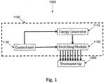
- Fig. 1 shows a schematic ( 1000 ) of the principal parts of an embodiment of the device.
- the device comprises a reusable handheld applicator ( 1100 ) and a disposable treatment tip ( 1200 ), comprising electrodes (not shown) and protruding conducting elements (not shown).
- the handheld applicator ( 1100 ) comprises an energy generator ( 1110 ) to generate the energy to be applied to the skin tissue and a switching module ( 1120 ) to control transfer of energy to the skin tissue, so as to provide fractional RF treatment of the skin.
- the energy generator ( 1110 ) and switching module ( 1120 ) are controlled by a control unit ( 1130 ).
- the energy generator ( 1110 ) produces RF energy, which can be applied to a skin volume as an AC voltage and current via the protruding conducting elements, Current is delivered to the switching module ( 1120 ), which can switch the voltage and current in a predefined sequence to the different electrodes to provide the fractional RF treatment.
- the control unit ( 1130 ) controls the sequence of switching, namely, the order in which switches are closed and opened; the pulse duration, the time at least one switch is closed and energy is suppliable to a skin volume; and the delay time, the time where no switches are closed and no energy is applied to the skin volume.
- controllable by the control unit ( 1130 ) are the frequency of the energy; there can be many frequencies of the energy in any one pulse and the frequency and delivered energy can vary during a pulse.
- the switching module ( 1120 ) and energy generator ( 1110 ) can be close to each other or be separated.
- the applicator comprises both the switching module ( 1120 ) and the energy generator ( 1110 ).
- Fig. 2 shows a not-preferred embodiment of a switching module ( 1120 ) adapted to provide fractional RF treatment by means of current delivered to a skin volume.
- Line A ( 1122 ) from the energy generator is split in the switching module into a plurality of N branches ( 1123 ), where N is the number of electrodes in the treatment tip ( 1200 ).
- Each branch comprises an On/Off switch (Sw A1 , ..., A n), 1124 ).
- Sw A1 , ..., A n On/Off switch
- the electrical current passes through the closed switch (or switches) and through an electrode (not shown) and protruding conducting element (not shown) in the treatment tip ( 1200 ) and returns through tissue (not shown and a return electrode ( 1121 ) to Line B ( 1128 ).
- the return electrode ( 1121 ) can be part of the treatment tip ( 1200 ) or it can be a separate pad connected to the patient's body.
- the return electrode ( 1121 ) comprises at least one protruding conducting element; in other variants the return electrode ( 1121 ) does not comprise a protruding conducting element and contacts the surface of the skin only.
- the voltage V applied to the body can be measured across Lines A ( 1122 ) and B ( 1128 ).
- Fig. 3 shows another embodiment of a switching module ( 1120 ) adapted to provide fractional RF treatment by means of a current delivered to a skin volume.
- at least one of the electrodes preferably a minority thereof is active (delivers current through the at least one electrode (not shown) and at least one protruding conducting element (not shown) into the tissue (not shown)) and the rest of the electrodes (preferably a majority thereof) form a return path.
- Lines A ( 1122 ) and B ( 1128 ) come from the energy generator. Each line splits into a plurality of N parallel branches ( 1123 , 1129 ) where N is the number of electrodes in the treatment tip ( 1200 ).
- Each branch includes an On/Off switch (Sw A1, ..., A n, 1124 ; Sw B1 , ..., Bn, 1127 ) which can reversibly connect one branch of Line A ( 1123 ), and one branch of Line B ( 1129 ) to an electrode in the treatment tip ( 1200 ).
- Sw A1, ..., A n, 1124 ; Sw B1 , ..., Bn, 1127 can reversibly connect one branch of Line A ( 1123 ), and one branch of Line B ( 1129 ) to an electrode in the treatment tip ( 1200 ).
- the switches A1 , ..., A n ( 1124 ) in Line A ( 1122 ) can be closed; the remainder will be open.
- the switches B1 , ..., B n, ( 1127 ) corresponding to open switches A1, ...
- a n ( 1124 ) in Line A ( 1122 ) will be closed, while the switches corresponding to closed switches A1 , ..., An ( 1124 ) in Line A ( 1122 ) will be open.
- the electrical current will pass through the closed switches A1 , ..., A n, ( 1124 ) in Line A ( 1122 ) to the treatment tip ( 1200 ) and return back through closed switches B1, ..., B n, ( 1127 ) in Line B ( 1128 ).
- Fig. 3 allows work without a return electrode but requires twice as many switches as the not-preferred embodiment shown in Fig. 1 .
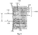
- Fig. 4 shows another embodiment of a switching module ( 1120 ) adapted to provide fractional RF treatment by means of a current delivered to a skin volume.
- Lines A ( 1122 ) and B ( 1128 ) come from the energy generator.
- Each line splits into a plurality of N parallel branches ( 1123 , 1129 ) where N is the number of electrodes in the treatment tip ( 1200 ).
- Branches of Line A include an On/Off switch (Sw A1 , ..., A n, 1124 ) which can reversibly connect one branch of Line A ( 1123 ), and one branch of Line B ( 1129 ) to an electrode in the treatment tip ( 1200 ).
- resistors R1, ..., R n instead of switches B1, ..., B n ( 1127 , Fig. 3 ) connect all the electrodes (not shown) in the treatment tip ( 1200 ) via the branches ( 1129 ) to Line B ( 1128 ).
- At least one of the switches A1 , ..., A n ( 1124 ) in Line A ( 1122 ) can be closed; the remainder will be open. Electrical current will pass through the closed switches A 1, ..., A n, ( 1124 ) in Line A ( 1122 ) to the treatment tip ( 1200 ) and return back through the resistors R 1, ..., R n, ( 1129 ) in Line B ( 1128 ).
- the resistance of these resistors R1, ..., R n ( 1129 ) should be much greater than the typical impedance of the portion of a patient's skin under a single electrode. If, in Line A ( 1122 ), one switch A1 , ..., A n ( 1124 ) is closed, the electrical current will pass through this switch to the tissue. The alternative path through the resistor will take only a small portion of the current, since the resistance of the resistor is much greater than that of the tissue. The return path is through the remainder of the electrodes (not shown) in the treatment tip ( 1200 ) and the remainder of the resistors R 1, ..., R n ( 1129 ).
- resistors R1, ..., R n ( 1129 ) are connected in parallel and therefore overall resistance will be low so that energy losses in the resistors R 1, ..., R n ( 1129 ) will be small.
- resistors can function as current limiters, which helps to prevent pain and helps to distribute current homogenously across the electrodes.
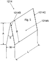
- Fig. 5 shows a schematic of the distal end of a protruding conducting element ( 1214 ); the electrode ( 1210 ) to which it is attached is not shown.
- the protruding conducting element ( 1214 ) forms substantially a triangular prism, with the square base of the prism attached to an electrode ( 1210 , see Figs. 7 and 8 , below).
- the square base has a length L, typically about 150 ⁇ m and a width W. Therefore, the length of the protruding conducting element ( 1214 ) and, typically, the electrode ( 1210 ), is L, and the width W of the base of the end faces of the prism is about 150 ⁇ m.
- the angle subtended by the distal end of the end faces, ⁇ is typically between about 20° and about 50°; preferably, the angle ⁇ is about 30°.
- Table 1 shows typical values of ⁇ , A, B and the ratio A/B. Table 1: A, B, and A/B as a function of angle ⁇ . Angle ⁇ A B Ratio A/B 20° 567 576 0.98 30° 373 387 0.96 50° 214 230 0.93
- the ratio A/B will be between 0.9 and 0.995 in embodiments of the device; in preferred embodiments, it is about 0.96.
- each hypotenuse ( 1214B ) is collinear with an edge ( 1214C ) of an end face.
- the side faces ( 1214A ) of the prism need not be flat; the edges ( 1214C ) of the side faces ( 1214A ) need not be straight lines and, therefore, the edges ( 1214C ) of the side faces ( 1214A ) need not have the same length as the hypotenuse (length B, 1214B, dashed line).
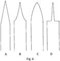
- Fig. 6A-D shows cross-sections of non-limiting exemplary embodiments of protruding conducting elements.
- Fig. 6A shows a triangular protruding conducting element like that in Fig. 5
- Fig. 6B shows an arcuate protruding conducting element in which the sides faces are curved inward
- Fig. 6C shows an arcuate protruding conducting element in which the sides faces are curved outward
- Fig. 6D shows a narrow triangular protruding conducting element with side faces curving outward at the distal end of the protruding conducting element and inward at the proximal end of the protruding conducting element.
- the narrower the tip of the distal end of the protruding conducting element and the more slowly the protruding conducting element widens toward its proximal end the less pain during penetration of the protruding conducting element into the skin, but the more blunting of the distal end of the protruding conducting element during use.
- the wider the tip of the distal end of the protruding conducting element and the more rapidly the protruding conducting element widens toward its proximal end the more pain during use, but the longer the protruding conducting element will last.
- a protruding conducting element angle ⁇ (see Fig. 5 , hereinabove) of about 30°, as described hereinabove, is a good compromise between perceived pain and protruding conducting element durability and that protruding conducting element angles ⁇ in the range of 20° - 50° provide an acceptable compromise between perceived pain and protruding conducting element durability.
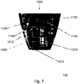
- Fig. 7 shows an embodiment of the device ( 1000 ), showing the distal end of the reusable handheld applicator ( 1100 ) and the disposable treatment tip ( 1200 ), while Fig. 8 shows a close-up of the region of the device ( 1000 ) comprising the contacts ( 1146 , 1212 ).
- the distal end of the reusable handheld applicator ( 1100 ) is shown in the upper part of Fig. 8 and the proximal end of the disposable treatment tip ( 1200 ) is shown in the lower part of Fig. 8 .
- the handheld applicator ( 1100 ) comprises a PCB ( 1142 ).
- the switching module ( 1120 , Figs. 1-4 , hereinabove), the control unit ( 1130 , Fig. 1 , hereinabove), and the energy generator ( 1110 , Fig. 1 , hereinabove) are mounted on the PCB ( 1142 ), with tracks on the PCB ( 1142 ) providing electrical connection between the switching module ( 1120 , Figs. 1-4 , hereinabove), the control unit ( 1130, Fig. 1 , hereinabove), and the energy generator ( 1110 , Fig. 1 , hereinabove).
- the PCB ( 1142 ) is near the upper edge of the figure.
- the applicator also comprises at least one connector ( 1144 ) and at least one contactor ( 1146 ), in electrical connection with the switching module ( 1120, Figs. 1-4 , hereinabove).
- connectors ( 1144 ) and contactors ( 1146 ) form part of a connection mechanism providing electrical connection between switches ( 1124 , not shown) in the applicator ( 1100 ) and electrodes ( 1126 , not shown) in the treatment tip ( 1200 ).
- At least part of the energy generator ( 1110 , Fig. 1 , hereinabove) comprises a separate unit.
- power for the energy generator can be mains power, supplied wiredly from a wall socket.
- the energy generator forms a separate unit, wiredly connectable to the applicator.
- the treatment tip ( 1200 ) is reversibly connectable to the applicator ( 1100 ).
- electrical connection is provided via physical contact between the contactors ( 1146 ) in the applicator and electrode contacts ( 1212 ) at the proximal end of the electrodes ( 1210 ) in the treatment tip ( 1200 ).
- Each contactor ( 1146 ) typically comprises a pin attached to the applicator ( 1100 ). In various embodiments, a small amount of movement of the contactor ( 1146 ) is possible, the contactor ( 1146 ) is flexible, and any combination thereof.
- the contactor ( 1146 ) can comprise a flexible and movable pad attached to the applicator ( 1100 ).
- the attachment of the contactors ( 1146 ) to the applicator ( 1100 ) ensures that the treatment tip ( 1200 ) can be reliably connected to the applicator ( 1100 ) and that, after connection of the treatment tip to the applicator to the treatment tip, the contactors ( 1146 ) and the electrode contacts ( 1212 ) will be either touching each other or in close physical proximity to each other.
- contactors ( 1146 ) are comprised of stainless steel because they contact the stainless steel proximal end of the electrode contact ( 1212 ) in the disposable tip, and the material of the contactor should be at least as hard as the material in the disposable tip which it is contacting.
- the contactor in the applicator is copper or other high-conductivity material, while the contact in the treatment tip, like the electrode contact of the present device ( 1212, Fig. 7 , hereinbelow) is of stainless steel.
- both the contactors ( 1146 ) and electrode contacts ( 1212 ) are of the same material, preferably stainless steel, ensuring good electrical connection between the contactors ( 1146 ) and the electrode contacts ( 1212 ), while good electrical connection between the contactors ( 1146 ) and the PCB ( 1142 ) is provided for by connectors ( 1144 ), preferably spring-like connectors.
- the connectors ( 1144 ) are coil springs. Connectors ( 1144 ) such as springs provide for good electrical connection between the contactors ( 1146 ) and the PCB (1 1 42).
- electrical connection between the PCB ( 1142 ) and the contactors ( 1146 ) (and therefore the electrodes ( 1210 )) is via the connectors ( 1144 ), which are firmly attached at their proximal ends to electrical contacts on the PCB ( 1142 ) and are firmly attached at their distal ends to the side of the contactors ( 1146 ).
- the connectors ( 1144 ) comprise a spiral spring, with the proximal portion of the contactors ( 1146 ) enclosed within the bore of the spring, thus maintaining the alignment of the contactors ( 1146 ) with respect to the electrodes ( 1146 ) and also ensuring that there is continuing good-quality electrical contact between the PCB ( 1142 ) and the electrodes ( 1210 ).
- Springs can be leaf springs, coil springs, or any other form of spring known in the art.
- the springs are coil springs, as shown in Figs. 7 and 8 .
- Springs can be of any material with high strength, a high elastic limit, a low Young's modulus and a wide elastic range. Springs can comprise iron, copper, tin, aluminum, vanadium, beryllium, nickel, chromium, plastic and any combination thereof. Exemplary spring materials include, but are not limited to, high carbon steel, alloy steel, stainless steel, phosphor bronze, beryllium copper, Monel, and Inconel. In preferred embodiments, the springs are of stainless steel.
- the disposable treatment tip ( 1200 ) comprises electrodes ( 1210 ) with protruding conducting elements ( 1214 ) at their distal end.
- the electrodes ( 1210 ) are in electrical communication with electrode contacts ( 1212 ).
- each electrode ( 1210 ) forms a single part which comprises at least one electrode contact ( 1212 ) at its proximal end and at least one protruding conducting element ( 1214 ) at its distal end.
- each electrode ( 1210 ) comprises two electrode contacts ( 1212 ).
- the electrodes ( 1210 ), electrode contacts ( 1212 ) and protruding conducting elements ( 1214 ) are comprised of stainless steel, but any material with good conductivity can be used, for non-limiting example, copper, gold, alloys thereof, conductive polymers and any combination thereof.
- Stainless steel is preferably used for the electrodes because of its strength and biocompatibility, which are required for the protruding conducting elements.
- each electrode ( 1210 ) has four protruding conducting elements ( 1214 ), although the number of protruding conducting elements ( 1214 ) can range from about 1 to about 4.
- each electrode ( 1210 ) has two electrode contacts ( 1212 ), with each electrode contact ( 1212 ) in electrical communication with one contactor ( 1146 ), so that there are twice as many electrode contacts ( 1212 ), contactors ( 1146 ) and connectors ( 1144 ) as there are electrodes ( 1210 ).
- Fig. 9 shows a schematic of the distal portion of an exemplary electrode ( 1210 ) with four protruding conducting elements ( 1214 ) at its distal end.
- the protruding conducting elements have triangular end faces and flat side faces.
- the side faces can curve inward ( Fig. 6B , hereinabove), can curve outward ( Fig. 6C , hereinabove), can curve both inward and outward ( Fig. 6D , hereinabove), and any combination thereof.
- fractional RF treatment is applied by having the RF pulse applied to a plurality of electrodes; preferably, subsequent pulses are applied to a different plurality of electrodes so as to limit heating of the tissue and minimize pain to the subject.
- fractional RF treatment is applied by having each RF pulse applied to a single electrode.
- Fractional RF treatments can comprise:
- the electrodes excited in one pulse are at a position as physically distant as is practicable from the electrodes excited in the previous pulse, so as to minimize further RF heating in a volume of tissue already heated by a previous pulse. By this means, overheating of tissue is prevented and pain is minimized.
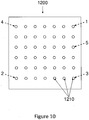
- FIG. 10 A non-limiting schematic example of a portion of a fractional RF treatment comprising a sequence of excitations in a square array of electrodes is given in Fig. 10 .
- the distal end of a treatment tip ( 1200 ) is shown, comprising 42 electrodes ( 1210 ) in a 6 X 7 array.
- the first electrode excited ( 1 , dashed arrow) is at the top right of the array.
- the second electrode excited ( 2 , dashed arrow) is at the bottom left.
- the third electrode ( 3 , dashed arrow) is at bottom right, and the fourth ( 4, dashed arrow) at top left. This is followed by the right-most electrode in the third (upper middle) row ( 5 , dashed arrow).
- the next in the sequence would be the left-most electrode in the fourth (lower middle) row, and so on.
- the system reduces side effects and/or harmful effects of the electromagnetic pulses and/or the deep tissue diathermy such that the reduction of side effects and/or said harmful effects is greater than the sum of the reduction due to the electromagnetic pulses and/or the reduction due to the deep tissue diathermy.
- the surface of the skin can be pre-cooled and/or cooled during treatment to avoid damage to the skin in the area between protruding conducting elements.
- Skin cooling can be provided by contact cooling, by applying a pre-cooled liquid or cryogen spray directly to the skin and any combination thereof.
- Contact cooling can be by means of a cooling mechanism in the applicator, which will also ensure a more uniform heat distribution in the electrodes in the region of the protruding conducting elements.
- Contact cooling by means of a cooling mechanism in the applicator can be achieved by circulating a cooling fluid through tubes in the applicator.
- Contact cooling can be by means of a pre-cooled liquid applied directly to the skin; a pre-cooled liquid applied to the skin via tubes within the applicator, the tubes contacting the skin; a thermo-electric contact cooler and any combination thereof.
- An embodiment of the device has a disposable treatment tip with 160 protruding conducting elements contacting tissue.
- the protruding conducting elements are divided to 40 groups of 4 protruding conducting elements each.
- Each group of 4 protruding conducting elements is connected to one electrode in the device ( Fig. 9 ).
- the device applies RF energy to one electrode (one group of 4 protruding conducting elements) at a time.
- the total energy delivered to each protruding conducting element can be up to 62 mJ, with the total energy in one application (comprising sequential application to all 160 protruding conducting elements) can be up to 9.92J.
- the distance between protruding conducting elements is 1 mm and the density of the protruding conducting elements is 120 protruding conducting elements/cm 2 .
- Each protruding conducting element has the shape of micro-knife (see Fig. 6A , hereinabove), with the angle subtended by the distal end of the micro-knife being 30°.
- the area of contact of each protruding conducting element is 20 ⁇ m X 150 ⁇ m.
- the depth of penetration is between 200 ⁇ m and 500 ⁇ m.
- Energy delivery to the protruding conducting elements is controlled by means of two parameters: RMS voltage of the RF energy (between about 220 V and 280 V) and pulse duration (between about 5 ms and about 30 ms).
- the sensation of pain was decreased by regulating the separation in time of the pulses (about 15 ms between pulses).
Landscapes
- Health & Medical Sciences (AREA)
- Engineering & Computer Science (AREA)
- Life Sciences & Earth Sciences (AREA)
- Surgery (AREA)
- Animal Behavior & Ethology (AREA)
- Veterinary Medicine (AREA)
- Nuclear Medicine, Radiotherapy & Molecular Imaging (AREA)
- Public Health (AREA)
- Biomedical Technology (AREA)
- General Health & Medical Sciences (AREA)
- Otolaryngology (AREA)
- Molecular Biology (AREA)
- Medical Informatics (AREA)
- Heart & Thoracic Surgery (AREA)
- Physics & Mathematics (AREA)
- Plasma & Fusion (AREA)
- Electrotherapy Devices (AREA)
- Surgical Instruments (AREA)
- Media Introduction/Drainage Providing Device (AREA)
- Oral & Maxillofacial Surgery (AREA)
- Plastic & Reconstructive Surgery (AREA)
- Radiology & Medical Imaging (AREA)
Claims (20)
- Système de traitement de la peau par chauffage d'au moins un volume défini de peau, comprenant :a. au moins une pointe de traitement comprenant N électrodes, N étant un entier supérieur ou égal à 1; au moins une desdites électrodes ayant au moins un élément conducteur faisant saillie ; au moins un desdits éléments conducteurs faisant saillie est caractérisé par des dimensions de hauteur A et d'hypoténuse B, au moins un desdits éléments conducteurs faisant saillie est configuré pour pénétrer la surface de la peau en au moins un emplacement défini; au moins une desdites électrodes est configurée pour appliquer de l'énergie audit au moins un volume de peau, de manière à chauffer ledit au moins un volume de peau; etb. un applicateur comprenant ladite au moins une électrode et ledit au moins un élément conducteur faisant saillie ;dans lequel le rapport A/B est compris entre 0,9 et 0,995, caractérisé en ce que ledit applicateur comprend en outre au moins un générateur d'énergie configuré pour appliquer ladite énergie au moyen de ladite au moins une électrode et dudit au moins un élément conducteur faisant saillie.
- Système selon la revendication 1, dans lequel au moins l'un des éléments suivants est vrai (a) au moins un desdits éléments conducteurs faisant saillie est configuré pour pénétrer à travers la couche cornée de ladite peau; (b) ledit au moins un volume de peau est un tissu situé sous ladite peau ; dans lequel en outre ledit au moins un volume de peau est un tissu situé sous la couche cornée de ladite peau; (c) ledit applicateur comprend en outre au moins un module de commutation comprenant au moins un commutateur, chacune desdites au moins une électrode pouvant être connectée électriquement de manière réversible à au moins l'un des générateurs d'énergie au moyen d'au moins l'un des commutateurs; (d) ledit système comprenant en outre un mécanisme pour refroidir au moins une partie de ladite peau, ledit mécanisme de refroidissement étant choisi dans un groupe comprenant : un liquide pré-refroidi appliqué directement sur ladite peau ; un liquide pré-refroidi appliqué sur ladite peau par l'intermédiaire de tubes à l'intérieur dudit applicateur, lesdits tubes étant en contact avec ladite peau ; une pulvérisation pré-refroidie appliquée sur ladite peau ; une pulvérisation cryogénique appliquée sur ladite peau ; un refroidisseur de contact thermoélectrique et toute combinaison de ceux-ci ; (e) et toute combinaison de ceux-ci.
- Système selon la revendication 1, dans lequel ledit traitement est un traitement RF ; dans lequel au moins un desdits générateurs d'énergie fournit une tension dans au moins l'une des gammes suivantes :a. la tension appliquée est comprise entre 160 V et 320 V RMS environ ;b. la tension appliquée est comprise entre 180 V et 300 V RMS environ ; etc. la tension appliquée est comprise entre environ 220 V et 280 V RMS.
- Système selon la revendication 1, dans lequel ledit applicateur comprend en outre au moins une unité de contrôle apte à réguler l'application de ladite énergie.
- Système selon la revendication 4, dans lequel ladite unité de commande est adaptée pour surveiller les paramètres physiques de la peau et modifier l'énergie appliquée en conséquence.
- Système selon la revendication 1, comprenant en outre au moins un commutateur adapté pour connecter de manière réversible au moins un desdits générateurs d'énergie à au moins une desdites électrodes ; dans lequel au moins un desdits commutateurs est adapté pour connecter simultanément un nombre M d'électrodes à au moins un desdits générateurs d'énergie, M étant un entier compris entre 1 et N.
- Système selon la revendication 6, dans lequel le rapport M/N se situe dans une plage choisie dans un groupe comprenant: 1/N à environ 10% ; environ 10% à environ 25% et plus d'environ 25% ; dans lequel au moins l'un des éléments suivants est considéré comme vrai: (a) N vaut environ 40 ; (b) chaque électrode comprend entre environ 1 et environ 5 desdits éléments conducteurs faisant saillie ; (c) chaque électrode comprend 4 lesdits éléments conducteurs faisant saillie ; (d) la distance entre lesdits éléments conducteurs faisant saillie est d'environ 1 mm ; et (e) la densité desdits éléments conducteurs faisant saillie est d'environ 120 par cm2 ; et toute combinaison de ceux-ci.
- Système selon la revendication 6, dans lequel ledit élément conducteur en saillie a essentiellement la forme d'un prisme caractérisé par une base rectangulaire de longueur L et de largeur W, deux faces latérales à quatre côtés de longueur L et deux faces d'extrémité à trois côtés de ladite hauteur A, de ladite hypoténuse B et de ladite largeur W, ladite base jointe à ladite électrode ; en outre dans lequel au moins un des éléments suivants est vrai :a. ladite longueur L est dans une plage d'environ 25 µm à environ 500 µm ;b. ladite longueur L est d'environ 150 µm ;c. ledit angle Θ se situe dans une plage d'environ 10 ° à environ 50 ° ;d. ledit angle Θ est d'environ 30 ° ; ete. lesdites faces latérales dudit prisme triangulaire ont une forme choisie dans un groupe constitué des méplats plats et incurvés vers l'intérieur, incurvés vers l'extérieur et de toute combinaison de ceux-ci.
- Système selon la revendication 1, dans lequel au moins l'un des éléments suivants est vrai :a. ladite électrode est constituée d'un matériau choisi dans un groupe constitué d'acier inoxydable, de cuivre, d'or, de polymères conducteurs et de toute combinaison de ceux-ci ; etb. ladite électrode comprend de l'acier inoxydable.
- Système selon la revendication 1, dans lequel ledit embout de traitement peut être connecté électriquement de manière réversible audit module de commutation; dans lequel, en outre, ledit applicateur comprend en outre au moins un contacteur adapté pour établir ladite connexion électrique réversible entre au moins une desdites électrodes dans ledit embout de traitement et au moins un desdits commutateurs dans ledit module de commutation; en outre dans lequel au moins un des éléments suivants est vrai :a. ledit contacteur a sensiblement la forme d'un cylindre caractérisé par un axe longitudinal principal ;b. ledit contacteur est constitué d'un matériau choisi dans un groupe comprenant le cuivre, l'acier, l'or, un polymère conducteur et toute combinaison de ceux-ci ; etc. ledit contacteur comprend de l'acier inoxydable ;d. ledit contacteur est en contact physique avec ladite électrode sur au moins une partie d'un côté parallèle audit axe longitudinal principal ;e. le système comprenant en outre au moins un connecteur flexible, dans lequel ladite connexion électrique entre ledit au moins un commutateur et au moins une desdites électrodes se fait via ledit connecteur ;f. ledit connecteur est caractérisé par des propriétés analogues à des ressorts ;g. le système comprenant en outre une carte de circuit imprimé (PCB) adaptée pour établir une connexion électrique entre ledit au moins un module de commutation, ledit au moins un générateur d'énergie et au moins un desdits connecteurs ;h. et toute combinaison de ceux-ci.
- Système selon la revendication 1, dans lequel au moins l'un des éléments suivants est vrai :a. une durée dans la plage d'environ 5 ms à environ 30 ms entre l'activation et la désactivation d'au moins l'une desdites électrodes ;b. un temps de retard entre la désactivation et l'activation d'au moins l'une desdites électrodes dans une plage d'environ 1 ms à environ 30 ms ; etc. un délai d'environ 2 ms entre la désactivation et l'activation d'au moins une desdites électrodes ;d. ledit embout de traitement est jetable ;e. ledit applicateur est réutilisable ;f. ledit dispositif comprend plus d'une pointe de traitement pour traiter plus d'une partie du corps simultanément ; etg. toute combinaison de ceux-ci.
- Dispositif de traitement de la peau comprenant le système de la revendication 1 et comprenant en outre :a. au moins un module de commutation comprenant au moins un commutateur, chacune desdites électrodes pouvant être connectée électriquement de manière réversible audit au moins un générateur d'énergie au moyen d'au moins un desdits commutateurs ; ledit applicateur comprenant en outre ledit module de commutation ;b. au moins un contacteur pouvant être connecté électriquement à au moins une desdites électrodes ; etc. au moins un connecteur caractérisé par une extrémité proximale et une extrémité distale, ledit connecteur étant connecté électriquement à son extrémité proximale à au moins un interrupteur et connecté électriquement à son extrémité distale à au moins un desdits contacteurs ;dans lequel ledit connecteur est constitué d'un matériau flexible et ledit contacteur et ladite électrode sont constitués d'un matériau rigide,
dans lequel au moins une partie de ladite énergie est applicable audit au moins un volume de peau au moyen de ladite connexion électrique. - Dispositif selon la revendication 12, dans lequel au moins l'un des éléments suivants est vrai : (a) ledit connecteur est caractérisé par des propriétés analogues à celles d'un ressort; (b) ledit dispositif comprend en outre une carte de circuit imprimé (PCB) adaptée pour établir une connexion électrique entre ledit au moins un module de commutation, ledit au moins un générateur d'énergie et au moins un desdits connecteurs; (c) ladite pointe de traitement peut être connectée électriquement de manière réversible audit module de commutation; (d) au moins l'un desdits éléments conducteurs faisant saillie est configuré pour couper à travers la couche cornée de ladite peau; (e) ledit au moins un volume de peau discret est un tissu situé sous ladite peau; dans lequel en outre ledit au moins un volume de peau distinct est un tissu situé sous la couche cornée de ladite peau; (f) toute combinaison de ceux-ci.
- Dispositif selon la revendication 12, dans lequel au moins l'un des éléments suivants est vrai :a. ledit contacteur a sensiblement la forme d'un cylindre caractérisé par un axe longitudinal principal ;b. ledit contacteur est constitué d'un matériau choisi dans un groupe comprenant le cuivre, l'acier, l'or, un polymère conducteur et toute combinaison de ceux-ci ;c. ledit contacteur est en contact physique avec ladite électrode sur au moins une partie d'un côté parallèle audit axe longitudinal principal ; etd. ledit contacteur comprend de l'acier inoxydable.
- Dispositif selon la revendication 12, dans lequel au moins l'un des éléments suivants est vrai :a. ladite électrode est constituée d'un matériau choisi dans un groupe constitué d'acier inoxydable, de cuivre, d'or, de polymères conducteurs et de toute combinaison de ceux-ci ; etb. ladite électrode comprend de l'acier inoxydable.
- Dispositif selon la revendication 12, dans lequel ledit traitement est un traitement RF ; dans lequel au moins un desdits générateurs d'énergie fournit une tension dans au moins l'une des gammes suivantes :a. la tension appliquée est comprise entre 160 V et 320 V RMS environ ;b. la tension appliquée est comprise entre 180 V et 300 V RMS environ ; etc. la tension appliquée est comprise entre environ 220 V et 280 V RMS.
- Dispositif selon la revendication 12, dans lequel ledit applicateur comprend en outre au moins une unité de commande adaptée à réguler l'application de ladite énergie ; en outre, ladite unité de commande est adaptée pour surveiller les paramètres physiques de la peau et modifier l'énergie appliquée en conséquence.
- Dispositif selon la revendication 12, dans lequel au moins un desdits commutateurs est adapté pour connecter simultanément un nombre M d'électrodes à au moins un desdits générateurs d'énergie, M étant un entier compris entre 1 et N; dans lequel au moins l'un des éléments suivants est considéré comme vrai (a) le rapport M/N se situe dans une plage choisie dans un groupe comprenant: 1/N à environ 10% ; environ 10% à environ 25% et plus d'environ 25% ; (b) N vaut environ 40; (c) chaque électrode comprend entre environ 1 et environ 5 desdits éléments conducteurs faisant saillie ; (d) chaque électrode comprend 4 lesdits éléments conducteurs en saillie ; (e) la distance entre lesdits éléments conducteurs faisant saillie est d'environ 1 mm ; (f) la densité desdits éléments conducteurs faisant saillie est d'environ 120 par cm2; et toute combinaison de ceux-ci.
- Dispositif selon la revendication 12, dans lequel ledit élément conducteur faisant saillie a sensiblement la forme d'un prisme caractérisé par une base rectangulaire de longueur L et de largeur W, deux faces latérales à quatre côtés de longueur L et deux faces d'extrémité à trois côtés de ladite surface de hauteur A, d'hypoténuse B et de largeur W, ladite base jointe à ladite électrode ; en outre dans lequel au moins un des éléments suivants est vrai :a. ladite longueur L est dans une plage d'environ 25 µm à environ 500 µm ;b. ladite longueur L est d'environ 150 µm ;c. ledit angle Θ se situe dans une plage d'environ 10 ° à environ 50° ;d. ledit angle Θ est d'environ 30° ; ete. lesdites faces latérales dudit prisme ont une forme choisie dans un groupe constitué des formes plates, incurvées vers l'intérieur, incurvées vers l'extérieur et de toute combinaison de celles-ci.
- Dispositif selon la revendication 12, dans lequel au moins l'un des éléments suivants est vrai :a. une durée dans la plage d'environ 5 ms à environ 30 ms entre l'activation et la désactivation d'au moins l'une desdites électrodes ;b. un temps de retard dans la plage d'environ 1 ms à environ 30 ms entre l'activation et la désactivation d'au moins une desdites électrodes ;c. un délai d'environ 2 ms entre l'activation et la désactivation d'au moins l'une desdites électrodes ;d. ledit dispositif comprenant en outre un mécanisme pour refroidir au moins une partie de ladite peau, ledit mécanisme de refroidissement étant choisi dans un groupe comprenant: un liquide pré-refroidi appliqué directement sur ladite peau; un liquide pré-refroidi appliqué sur ladite peau par l'intermédiaire de tubes à l'intérieur dudit applicateur, lesdits tubes étant en contact avec ladite peau; une pulvérisation pré-refroidie appliquée sur ladite peau; une pulvérisation cryogénique appliquée sur ladite peau; un refroidisseur de contact thermoélectrique et toute combinaison de ceux-ci ;e. ledit embout de traitement est jetable ;f. ledit applicateur est réutilisable ;g. au moins un desdits générateurs d'énergie comporte un blindage électrostatique ; et,h. toute combinaison de ceux-ci.
Priority Applications (1)
| Application Number | Priority Date | Filing Date | Title |
|---|---|---|---|
| EP19173234.6A EP3542745B1 (fr) | 2013-04-14 | 2014-04-13 | Dispositif de traitement rf fractionné de la peau |
Applications Claiming Priority (2)
| Application Number | Priority Date | Filing Date | Title |
|---|---|---|---|
| US201361811750P | 2013-04-14 | 2013-04-14 | |
| PCT/IL2014/000021 WO2014170887A2 (fr) | 2013-04-14 | 2014-04-13 | Dispositif et méthode de traitement rf fractionné de la peau |
Related Child Applications (1)
| Application Number | Title | Priority Date | Filing Date |
|---|---|---|---|
| EP19173234.6A Division EP3542745B1 (fr) | 2013-04-14 | 2014-04-13 | Dispositif de traitement rf fractionné de la peau |
Publications (3)
| Publication Number | Publication Date |
|---|---|
| EP2986244A2 EP2986244A2 (fr) | 2016-02-24 |
| EP2986244A4 EP2986244A4 (fr) | 2017-02-22 |
| EP2986244B1 true EP2986244B1 (fr) | 2019-05-22 |
Family
ID=51687288
Family Applications (2)
| Application Number | Title | Priority Date | Filing Date |
|---|---|---|---|
| EP14784768.5A Active EP2986244B1 (fr) | 2013-04-14 | 2014-04-13 | Dispositif de traitement rf fractionné de la peau |
| EP19173234.6A Active EP3542745B1 (fr) | 2013-04-14 | 2014-04-13 | Dispositif de traitement rf fractionné de la peau |
Family Applications After (1)
| Application Number | Title | Priority Date | Filing Date |
|---|---|---|---|
| EP19173234.6A Active EP3542745B1 (fr) | 2013-04-14 | 2014-04-13 | Dispositif de traitement rf fractionné de la peau |
Country Status (6)
| Country | Link |
|---|---|
| US (2) | US11197713B2 (fr) |
| EP (2) | EP2986244B1 (fr) |
| CN (1) | CN105451679B (fr) |
| CA (2) | CA3092405A1 (fr) |
| ES (1) | ES2743185T3 (fr) |
| WO (1) | WO2014170887A2 (fr) |
Families Citing this family (19)
| Publication number | Priority date | Publication date | Assignee | Title |
|---|---|---|---|---|
| US20180001107A1 (en) | 2016-07-01 | 2018-01-04 | Btl Holdings Limited | Aesthetic method of biological structure treatment by magnetic field |
| US10695575B1 (en) | 2016-05-10 | 2020-06-30 | Btl Medical Technologies S.R.O. | Aesthetic method of biological structure treatment by magnetic field |
| KR200494027Y1 (ko) * | 2016-01-27 | 2021-07-20 | 비너스 컨셉트 리미티드 | 피부의 부분 rf 치료 장치 |
| US11464993B2 (en) | 2016-05-03 | 2022-10-11 | Btl Healthcare Technologies A.S. | Device including RF source of energy and vacuum system |
| US11534619B2 (en) | 2016-05-10 | 2022-12-27 | Btl Medical Solutions A.S. | Aesthetic method of biological structure treatment by magnetic field |
| EP3481495A4 (fr) * | 2016-07-07 | 2020-04-29 | Venus Concept Ltd | Appareil à usage esthétique utile pour accroître la régénération de la peau et procédés associés |
| US11141219B1 (en) | 2016-08-16 | 2021-10-12 | BTL Healthcare Technologies, a.s. | Self-operating belt |
| CN107551398A (zh) * | 2017-09-20 | 2018-01-09 | 重庆半岛医疗科技有限公司 | 一种用于腔道组织年轻化治疗的治疗头和治疗装置 |
| US11103308B2 (en) * | 2017-12-11 | 2021-08-31 | Covidien Lp | Reusable transmission network for dividing energy and monitoring signals between surgical devices |
| US12156689B2 (en) | 2019-04-11 | 2024-12-03 | Btl Medical Solutions A.S. | Methods and devices for aesthetic treatment of biological structures by radiofrequency and magnetic energy |
| US12558146B2 (en) | 2019-04-11 | 2026-02-24 | Btl Medical Solutions A.S. | Methods and devices for aesthetic treatment of biological structures by radiofrequency and magnetic energy |
| AU2020270557C1 (en) | 2019-04-11 | 2022-01-20 | Btl Medical Solutions A.S. | Methods and devices for aesthetic treatment of biological structures by radiofrequency and magnetic energy |
| US12220346B2 (en) * | 2019-11-15 | 2025-02-11 | Lightfective Ltd. | Applicator with thermal contact sensors |
| BR112022022112A2 (pt) | 2020-05-04 | 2022-12-13 | Btl Healthcare Technologies As | Dispositivo para tratamento não assistido do paciente |
| US11878167B2 (en) | 2020-05-04 | 2024-01-23 | Btl Healthcare Technologies A.S. | Device and method for unattended treatment of a patient |
| EP4146328A1 (fr) | 2020-05-05 | 2023-03-15 | Cynosure, LLC | Dispositifs à réseau d'aiguilles et méthodes associées |
| WO2023062563A1 (fr) | 2021-10-13 | 2023-04-20 | Btl Medical Solutions A.S. | Dispositifs de traitement esthétique de structures biologiques par énergie radiofréquence et magnétique |
| US11896816B2 (en) | 2021-11-03 | 2024-02-13 | Btl Healthcare Technologies A.S. | Device and method for unattended treatment of a patient |
| US20260097225A1 (en) | 2024-10-08 | 2026-04-09 | Btl Medical Solutions A.S. | Devices and methods for application of a magnetic field to the nervous system |
Family Cites Families (25)
| Publication number | Priority date | Publication date | Assignee | Title |
|---|---|---|---|---|
| US4561445A (en) * | 1983-05-25 | 1985-12-31 | Joseph J. Berke | Elongated needle electrode and method of making same |
| US5697909A (en) * | 1992-01-07 | 1997-12-16 | Arthrocare Corporation | Methods and apparatus for surgical cutting |
| US6142992A (en) * | 1993-05-10 | 2000-11-07 | Arthrocare Corporation | Power supply for limiting power in electrosurgery |
| US6837888B2 (en) * | 1995-06-07 | 2005-01-04 | Arthrocare Corporation | Electrosurgical probe with movable return electrode and methods related thereto |
| US6167291A (en) * | 1998-03-12 | 2000-12-26 | Cardima, Inc. | Protected pin connector for an electrophysiology catheter |
| DE60113965T2 (de) * | 2000-02-10 | 2006-07-06 | Potencia Medical Ag | Behandlung der harninkontinenz mit kabelloser energiezufuhr |
| US8251986B2 (en) * | 2000-08-17 | 2012-08-28 | Angiodynamics, Inc. | Method of destroying tissue cells by eletroporation |
| US20040162551A1 (en) * | 2000-12-15 | 2004-08-19 | Brown Tony R. | Method and device for creating transmural lesions |
| US6572613B1 (en) * | 2001-01-16 | 2003-06-03 | Alan G. Ellman | RF tissue penetrating probe |
| US20060047281A1 (en) * | 2004-09-01 | 2006-03-02 | Syneron Medical Ltd. | Method and system for invasive skin treatment |
| US8882766B2 (en) * | 2006-01-24 | 2014-11-11 | Covidien Ag | Method and system for controlling delivery of energy to divide tissue |
| US8496657B2 (en) * | 2006-02-07 | 2013-07-30 | P Tech, Llc. | Methods for utilizing vibratory energy to weld, stake and/or remove implants |
| US8273080B2 (en) * | 2006-10-16 | 2012-09-25 | Syneron Medical Ltd. | Methods and devices for treating tissue |
| JP5559539B2 (ja) * | 2006-10-18 | 2014-07-23 | べシックス・バスキュラー・インコーポレイテッド | 身体組織に望ましい温度作用を誘発するシステム |
| WO2008091983A2 (fr) * | 2007-01-25 | 2008-07-31 | Thermage, Inc. | Appareil et procédés de traitement pour induire des motifs de microbrûlure dans un tissu |
| US20080249523A1 (en) * | 2007-04-03 | 2008-10-09 | Tyco Healthcare Group Lp | Controller for flexible tissue ablation procedures |
| WO2008131302A2 (fr) * | 2007-04-19 | 2008-10-30 | The Foundry, Inc. | Procédés et appareils pour réduire la production de sueur |
| JP2011505899A (ja) * | 2007-12-05 | 2011-03-03 | シネロン メディカル リミテッド | 使い捨て可能な電磁気エネルギーアプリケータ及びそれを使用する方法 |
| US8357150B2 (en) * | 2009-07-20 | 2013-01-22 | Syneron Medical Ltd. | Method and apparatus for fractional skin treatment |
| US9675406B2 (en) * | 2010-02-16 | 2017-06-13 | Angiodynamics, Inc. | Ablation device with guide sleeves |
| US9005199B2 (en) * | 2010-06-10 | 2015-04-14 | Ethicon Endo-Surgery, Inc. | Heat management configurations for controlling heat dissipation from electrosurgical instruments |
| WO2012051433A2 (fr) * | 2010-10-13 | 2012-04-19 | Angiodynamics, Inc. | Système et procédé d'ablation électrique des tissus chez un patient |
| US10448992B2 (en) * | 2010-10-22 | 2019-10-22 | Arthrocare Corporation | Electrosurgical system with device specific operational parameters |
| WO2012110996A2 (fr) * | 2011-02-14 | 2012-08-23 | Syneron Medical Ltd. | Procédé et appareil pour traitement cosmétique de la peau |
| US20130165921A1 (en) * | 2011-08-24 | 2013-06-27 | Boston Scientific Scimed, Inc. | Device and methods for nerve modulation |
-
2014
- 2014-04-13 ES ES14784768T patent/ES2743185T3/es active Active
- 2014-04-13 EP EP14784768.5A patent/EP2986244B1/fr active Active
- 2014-04-13 CA CA3092405A patent/CA3092405A1/fr active Pending
- 2014-04-13 EP EP19173234.6A patent/EP3542745B1/fr active Active
- 2014-04-13 CA CA2913717A patent/CA2913717C/fr active Active
- 2014-04-13 WO PCT/IL2014/000021 patent/WO2014170887A2/fr not_active Ceased
- 2014-04-13 CN CN201480033888.7A patent/CN105451679B/zh active Active
- 2014-04-14 US US14/251,937 patent/US11197713B2/en active Active
-
2021
- 2021-12-10 US US17/548,316 patent/US20220096146A1/en active Pending
Non-Patent Citations (1)
| Title |
|---|
| None * |
Also Published As
| Publication number | Publication date |
|---|---|
| US20220096146A1 (en) | 2022-03-31 |
| US11197713B2 (en) | 2021-12-14 |
| EP3542745A1 (fr) | 2019-09-25 |
| WO2014170887A8 (fr) | 2015-06-11 |
| WO2014170887A2 (fr) | 2014-10-23 |
| CN105451679A (zh) | 2016-03-30 |
| CA3092405A1 (fr) | 2014-10-23 |
| CA2913717C (fr) | 2022-12-13 |
| EP3542745B1 (fr) | 2026-03-11 |
| US20140309628A1 (en) | 2014-10-16 |
| EP2986244A2 (fr) | 2016-02-24 |
| EP2986244A4 (fr) | 2017-02-22 |
| CA2913717A1 (fr) | 2014-10-23 |
| CN105451679B (zh) | 2022-08-05 |
| ES2743185T3 (es) | 2020-02-18 |
| WO2014170887A3 (fr) | 2015-03-12 |
Similar Documents
| Publication | Publication Date | Title |
|---|---|---|
| EP2986244B1 (fr) | Dispositif de traitement rf fractionné de la peau | |
| US11298259B2 (en) | Device and method for fractional RF treatment of the skin | |
| EP2456380B1 (fr) | Appareil pour traitement fractionné de la peau | |
| EP2401026B1 (fr) | Rajeunissement électrique de la peau | |
| KR20220065620A (ko) | 고주파를 이용한 피부 관리 장치 | |
| Duncan et al. | Basic radiofrequency: physics and safety and application to aesthetic medicine | |
| KR200494027Y1 (ko) | 피부의 부분 rf 치료 장치 | |
| US20240335660A1 (en) | Electrical applicators with non-penetrating electrodes for applying energy to tissue surfaces | |
| HK40014893A (en) | Device and method for fractional rf treatment of the skin | |
| JP3206745U (ja) | 皮膚のフラクショナルrfトリートメントのためのデバイス及び方法 |
Legal Events
| Date | Code | Title | Description |
|---|---|---|---|
| PUAI | Public reference made under article 153(3) epc to a published international application that has entered the european phase |
Free format text: ORIGINAL CODE: 0009012 |
|
| 17P | Request for examination filed |
Effective date: 20151127 |
|
| AK | Designated contracting states |
Kind code of ref document: A2 Designated state(s): AL AT BE BG CH CY CZ DE DK EE ES FI FR GB GR HR HU IE IS IT LI LT LU LV MC MK MT NL NO PL PT RO RS SE SI SK SM TR |
|
| AX | Request for extension of the european patent |
Extension state: BA ME |
|
| DAX | Request for extension of the european patent (deleted) | ||
| A4 | Supplementary search report drawn up and despatched |
Effective date: 20170125 |
|
| RIC1 | Information provided on ipc code assigned before grant |
Ipc: A61B 18/14 20060101AFI20170119BHEP |
|
| STAA | Information on the status of an ep patent application or granted ep patent |
Free format text: STATUS: EXAMINATION IS IN PROGRESS |
|
| 17Q | First examination report despatched |
Effective date: 20180124 |
|
| GRAP | Despatch of communication of intention to grant a patent |
Free format text: ORIGINAL CODE: EPIDOSNIGR1 |
|
| STAA | Information on the status of an ep patent application or granted ep patent |
Free format text: STATUS: GRANT OF PATENT IS INTENDED |
|
| INTG | Intention to grant announced |
Effective date: 20181114 |
|
| GRAS | Grant fee paid |
Free format text: ORIGINAL CODE: EPIDOSNIGR3 |
|
| GRAA | (expected) grant |
Free format text: ORIGINAL CODE: 0009210 |
|
| STAA | Information on the status of an ep patent application or granted ep patent |
Free format text: STATUS: THE PATENT HAS BEEN GRANTED |
|
| AK | Designated contracting states |
Kind code of ref document: B1 Designated state(s): AL AT BE BG CH CY CZ DE DK EE ES FI FR GB GR HR HU IE IS IT LI LT LU LV MC MK MT NL NO PL PT RO RS SE SI SK SM TR |
|
| REG | Reference to a national code |
Ref country code: GB Ref legal event code: FG4D |
|
| REG | Reference to a national code |
Ref country code: CH Ref legal event code: EP |
|
| REG | Reference to a national code |
Ref country code: IE Ref legal event code: FG4D |
|
| REG | Reference to a national code |
Ref country code: DE Ref legal event code: R096 Ref document number: 602014047303 Country of ref document: DE |
|
| REG | Reference to a national code |
Ref country code: AT Ref legal event code: REF Ref document number: 1135138 Country of ref document: AT Kind code of ref document: T Effective date: 20190615 |
|
| REG | Reference to a national code |
Ref country code: NL Ref legal event code: MP Effective date: 20190522 |
|
| REG | Reference to a national code |
Ref country code: LT Ref legal event code: MG4D |
|
| PG25 | Lapsed in a contracting state [announced via postgrant information from national office to epo] |
Ref country code: NO Free format text: LAPSE BECAUSE OF FAILURE TO SUBMIT A TRANSLATION OF THE DESCRIPTION OR TO PAY THE FEE WITHIN THE PRESCRIBED TIME-LIMIT Effective date: 20190822 Ref country code: AL Free format text: LAPSE BECAUSE OF FAILURE TO SUBMIT A TRANSLATION OF THE DESCRIPTION OR TO PAY THE FEE WITHIN THE PRESCRIBED TIME-LIMIT Effective date: 20190522 Ref country code: FI Free format text: LAPSE BECAUSE OF FAILURE TO SUBMIT A TRANSLATION OF THE DESCRIPTION OR TO PAY THE FEE WITHIN THE PRESCRIBED TIME-LIMIT Effective date: 20190522 Ref country code: NL Free format text: LAPSE BECAUSE OF FAILURE TO SUBMIT A TRANSLATION OF THE DESCRIPTION OR TO PAY THE FEE WITHIN THE PRESCRIBED TIME-LIMIT Effective date: 20190522 Ref country code: HR Free format text: LAPSE BECAUSE OF FAILURE TO SUBMIT A TRANSLATION OF THE DESCRIPTION OR TO PAY THE FEE WITHIN THE PRESCRIBED TIME-LIMIT Effective date: 20190522 Ref country code: PT Free format text: LAPSE BECAUSE OF FAILURE TO SUBMIT A TRANSLATION OF THE DESCRIPTION OR TO PAY THE FEE WITHIN THE PRESCRIBED TIME-LIMIT Effective date: 20190922 Ref country code: SE Free format text: LAPSE BECAUSE OF FAILURE TO SUBMIT A TRANSLATION OF THE DESCRIPTION OR TO PAY THE FEE WITHIN THE PRESCRIBED TIME-LIMIT Effective date: 20190522 Ref country code: LT Free format text: LAPSE BECAUSE OF FAILURE TO SUBMIT A TRANSLATION OF THE DESCRIPTION OR TO PAY THE FEE WITHIN THE PRESCRIBED TIME-LIMIT Effective date: 20190522 |
|
| PG25 | Lapsed in a contracting state [announced via postgrant information from national office to epo] |
Ref country code: GR Free format text: LAPSE BECAUSE OF FAILURE TO SUBMIT A TRANSLATION OF THE DESCRIPTION OR TO PAY THE FEE WITHIN THE PRESCRIBED TIME-LIMIT Effective date: 20190823 Ref country code: BG Free format text: LAPSE BECAUSE OF FAILURE TO SUBMIT A TRANSLATION OF THE DESCRIPTION OR TO PAY THE FEE WITHIN THE PRESCRIBED TIME-LIMIT Effective date: 20190822 Ref country code: RS Free format text: LAPSE BECAUSE OF FAILURE TO SUBMIT A TRANSLATION OF THE DESCRIPTION OR TO PAY THE FEE WITHIN THE PRESCRIBED TIME-LIMIT Effective date: 20190522 Ref country code: LV Free format text: LAPSE BECAUSE OF FAILURE TO SUBMIT A TRANSLATION OF THE DESCRIPTION OR TO PAY THE FEE WITHIN THE PRESCRIBED TIME-LIMIT Effective date: 20190522 |
|
| REG | Reference to a national code |
Ref country code: AT Ref legal event code: MK05 Ref document number: 1135138 Country of ref document: AT Kind code of ref document: T Effective date: 20190522 |
|
| PG25 | Lapsed in a contracting state [announced via postgrant information from national office to epo] |
Ref country code: CZ Free format text: LAPSE BECAUSE OF FAILURE TO SUBMIT A TRANSLATION OF THE DESCRIPTION OR TO PAY THE FEE WITHIN THE PRESCRIBED TIME-LIMIT Effective date: 20190522 Ref country code: RO Free format text: LAPSE BECAUSE OF FAILURE TO SUBMIT A TRANSLATION OF THE DESCRIPTION OR TO PAY THE FEE WITHIN THE PRESCRIBED TIME-LIMIT Effective date: 20190522 Ref country code: EE Free format text: LAPSE BECAUSE OF FAILURE TO SUBMIT A TRANSLATION OF THE DESCRIPTION OR TO PAY THE FEE WITHIN THE PRESCRIBED TIME-LIMIT Effective date: 20190522 Ref country code: AT Free format text: LAPSE BECAUSE OF FAILURE TO SUBMIT A TRANSLATION OF THE DESCRIPTION OR TO PAY THE FEE WITHIN THE PRESCRIBED TIME-LIMIT Effective date: 20190522 Ref country code: DK Free format text: LAPSE BECAUSE OF FAILURE TO SUBMIT A TRANSLATION OF THE DESCRIPTION OR TO PAY THE FEE WITHIN THE PRESCRIBED TIME-LIMIT Effective date: 20190522 Ref country code: SK Free format text: LAPSE BECAUSE OF FAILURE TO SUBMIT A TRANSLATION OF THE DESCRIPTION OR TO PAY THE FEE WITHIN THE PRESCRIBED TIME-LIMIT Effective date: 20190522 |
|
| REG | Reference to a national code |
Ref country code: ES Ref legal event code: FG2A Ref document number: 2743185 Country of ref document: ES Kind code of ref document: T3 Effective date: 20200218 |
|
| REG | Reference to a national code |
Ref country code: DE Ref legal event code: R097 Ref document number: 602014047303 Country of ref document: DE |
|
| PG25 | Lapsed in a contracting state [announced via postgrant information from national office to epo] |
Ref country code: SM Free format text: LAPSE BECAUSE OF FAILURE TO SUBMIT A TRANSLATION OF THE DESCRIPTION OR TO PAY THE FEE WITHIN THE PRESCRIBED TIME-LIMIT Effective date: 20190522 |
|
| PLBE | No opposition filed within time limit |
Free format text: ORIGINAL CODE: 0009261 |
|
| STAA | Information on the status of an ep patent application or granted ep patent |
Free format text: STATUS: NO OPPOSITION FILED WITHIN TIME LIMIT |
|
| PG25 | Lapsed in a contracting state [announced via postgrant information from national office to epo] |
Ref country code: TR Free format text: LAPSE BECAUSE OF FAILURE TO SUBMIT A TRANSLATION OF THE DESCRIPTION OR TO PAY THE FEE WITHIN THE PRESCRIBED TIME-LIMIT Effective date: 20190522 |
|
| 26N | No opposition filed |
Effective date: 20200225 |
|
| PG25 | Lapsed in a contracting state [announced via postgrant information from national office to epo] |
Ref country code: PL Free format text: LAPSE BECAUSE OF FAILURE TO SUBMIT A TRANSLATION OF THE DESCRIPTION OR TO PAY THE FEE WITHIN THE PRESCRIBED TIME-LIMIT Effective date: 20190522 |
|
| PG25 | Lapsed in a contracting state [announced via postgrant information from national office to epo] |
Ref country code: SI Free format text: LAPSE BECAUSE OF FAILURE TO SUBMIT A TRANSLATION OF THE DESCRIPTION OR TO PAY THE FEE WITHIN THE PRESCRIBED TIME-LIMIT Effective date: 20190522 |
|
| PG25 | Lapsed in a contracting state [announced via postgrant information from national office to epo] |
Ref country code: MC Free format text: LAPSE BECAUSE OF FAILURE TO SUBMIT A TRANSLATION OF THE DESCRIPTION OR TO PAY THE FEE WITHIN THE PRESCRIBED TIME-LIMIT Effective date: 20190522 |
|
| REG | Reference to a national code |
Ref country code: CH Ref legal event code: PL |
|
| PG25 | Lapsed in a contracting state [announced via postgrant information from national office to epo] |
Ref country code: CH Free format text: LAPSE BECAUSE OF NON-PAYMENT OF DUE FEES Effective date: 20200430 Ref country code: LI Free format text: LAPSE BECAUSE OF NON-PAYMENT OF DUE FEES Effective date: 20200430 Ref country code: LU Free format text: LAPSE BECAUSE OF NON-PAYMENT OF DUE FEES Effective date: 20200413 |
|
| REG | Reference to a national code |
Ref country code: BE Ref legal event code: MM Effective date: 20200430 |
|
| PG25 | Lapsed in a contracting state [announced via postgrant information from national office to epo] |
Ref country code: BE Free format text: LAPSE BECAUSE OF NON-PAYMENT OF DUE FEES Effective date: 20200430 |
|
| PG25 | Lapsed in a contracting state [announced via postgrant information from national office to epo] |
Ref country code: IE Free format text: LAPSE BECAUSE OF NON-PAYMENT OF DUE FEES Effective date: 20200413 |
|
| PGFP | Annual fee paid to national office [announced via postgrant information from national office to epo] |
Ref country code: IT Payment date: 20210423 Year of fee payment: 8 |
|
| PG25 | Lapsed in a contracting state [announced via postgrant information from national office to epo] |
Ref country code: MT Free format text: LAPSE BECAUSE OF FAILURE TO SUBMIT A TRANSLATION OF THE DESCRIPTION OR TO PAY THE FEE WITHIN THE PRESCRIBED TIME-LIMIT Effective date: 20190522 Ref country code: CY Free format text: LAPSE BECAUSE OF FAILURE TO SUBMIT A TRANSLATION OF THE DESCRIPTION OR TO PAY THE FEE WITHIN THE PRESCRIBED TIME-LIMIT Effective date: 20190522 |
|
| PG25 | Lapsed in a contracting state [announced via postgrant information from national office to epo] |
Ref country code: MK Free format text: LAPSE BECAUSE OF FAILURE TO SUBMIT A TRANSLATION OF THE DESCRIPTION OR TO PAY THE FEE WITHIN THE PRESCRIBED TIME-LIMIT Effective date: 20190522 Ref country code: IS Free format text: LAPSE BECAUSE OF FAILURE TO SUBMIT A TRANSLATION OF THE DESCRIPTION OR TO PAY THE FEE WITHIN THE PRESCRIBED TIME-LIMIT Effective date: 20190922 |
|
| PG25 | Lapsed in a contracting state [announced via postgrant information from national office to epo] |
Ref country code: IT Free format text: LAPSE BECAUSE OF NON-PAYMENT OF DUE FEES Effective date: 20220413 |
|
| P01 | Opt-out of the competence of the unified patent court (upc) registered |
Effective date: 20230608 |
|
| PGFP | Annual fee paid to national office [announced via postgrant information from national office to epo] |
Ref country code: DE Payment date: 20250218 Year of fee payment: 12 |
|
| PGFP | Annual fee paid to national office [announced via postgrant information from national office to epo] |
Ref country code: ES Payment date: 20250508 Year of fee payment: 12 |
|
| PGFP | Annual fee paid to national office [announced via postgrant information from national office to epo] |
Ref country code: GB Payment date: 20260223 Year of fee payment: 13 |
|
| PGFP | Annual fee paid to national office [announced via postgrant information from national office to epo] |
Ref country code: FR Payment date: 20260223 Year of fee payment: 13 |