EP2986255B1 - Implantate zum einsatz in einer blutzirkulationspassage mit einem system zum trennen der proximalen arme - Google Patents
Implantate zum einsatz in einer blutzirkulationspassage mit einem system zum trennen der proximalen arme Download PDFInfo
- Publication number
- EP2986255B1 EP2986255B1 EP14721266.6A EP14721266A EP2986255B1 EP 2986255 B1 EP2986255 B1 EP 2986255B1 EP 14721266 A EP14721266 A EP 14721266A EP 2986255 B1 EP2986255 B1 EP 2986255B1
- Authority
- EP
- European Patent Office
- Prior art keywords
- proximal
- sleeve
- stop
- distal
- arms
- Prior art date
- Legal status (The legal status is an assumption and is not a legal conclusion. Google has not performed a legal analysis and makes no representation as to the accuracy of the status listed.)
- Not-in-force
Links
- 239000007943 implant Substances 0.000 title claims description 85
- 230000017531 blood circulation Effects 0.000 title claims description 22
- 238000004873 anchoring Methods 0.000 claims description 17
- 230000001746 atrial effect Effects 0.000 description 51
- 230000002861 ventricular Effects 0.000 description 39
- 238000009434 installation Methods 0.000 description 13
- 230000006355 external stress Effects 0.000 description 11
- 238000000034 method Methods 0.000 description 11
- 210000004115 mitral valve Anatomy 0.000 description 10
- 210000001519 tissue Anatomy 0.000 description 10
- 210000005240 left ventricle Anatomy 0.000 description 9
- 239000008280 blood Substances 0.000 description 6
- 210000004369 blood Anatomy 0.000 description 6
- 238000000926 separation method Methods 0.000 description 6
- 230000004087 circulation Effects 0.000 description 5
- 210000003709 heart valve Anatomy 0.000 description 4
- 238000003780 insertion Methods 0.000 description 4
- 230000037431 insertion Effects 0.000 description 4
- 210000005246 left atrium Anatomy 0.000 description 4
- 230000000747 cardiac effect Effects 0.000 description 3
- 230000008602 contraction Effects 0.000 description 3
- 239000004744 fabric Substances 0.000 description 3
- 230000037361 pathway Effects 0.000 description 3
- 230000000284 resting effect Effects 0.000 description 3
- 241001465754 Metazoa Species 0.000 description 2
- PXHVJJICTQNCMI-UHFFFAOYSA-N Nickel Chemical compound [Ni] PXHVJJICTQNCMI-UHFFFAOYSA-N 0.000 description 2
- 238000002716 delivery method Methods 0.000 description 2
- 230000000694 effects Effects 0.000 description 2
- 229910052751 metal Inorganic materials 0.000 description 2
- 239000002184 metal Substances 0.000 description 2
- 238000010992 reflux Methods 0.000 description 2
- 210000000591 tricuspid valve Anatomy 0.000 description 2
- 241000283690 Bos taurus Species 0.000 description 1
- 241000283073 Equus caballus Species 0.000 description 1
- 206010027727 Mitral valve incompetence Diseases 0.000 description 1
- 241000287107 Passer Species 0.000 description 1
- 206010067171 Regurgitation Diseases 0.000 description 1
- 241001080024 Telles Species 0.000 description 1
- RTAQQCXQSZGOHL-UHFFFAOYSA-N Titanium Chemical compound [Ti] RTAQQCXQSZGOHL-UHFFFAOYSA-N 0.000 description 1
- 210000001765 aortic valve Anatomy 0.000 description 1
- 238000007675 cardiac surgery Methods 0.000 description 1
- 230000001684 chronic effect Effects 0.000 description 1
- 239000000470 constituent Substances 0.000 description 1
- 230000007423 decrease Effects 0.000 description 1
- 230000002950 deficient Effects 0.000 description 1
- 230000007850 degeneration Effects 0.000 description 1
- 201000010099 disease Diseases 0.000 description 1
- 208000037265 diseases, disorders, signs and symptoms Diseases 0.000 description 1
- 239000000835 fiber Substances 0.000 description 1
- 229920005570 flexible polymer Polymers 0.000 description 1
- 238000009432 framing Methods 0.000 description 1
- 230000006870 function Effects 0.000 description 1
- 210000002837 heart atrium Anatomy 0.000 description 1
- 238000002513 implantation Methods 0.000 description 1
- 239000007937 lozenge Substances 0.000 description 1
- 230000014759 maintenance of location Effects 0.000 description 1
- 230000003387 muscular Effects 0.000 description 1
- 229910052759 nickel Inorganic materials 0.000 description 1
- HLXZNVUGXRDIFK-UHFFFAOYSA-N nickel titanium Chemical compound [Ti].[Ti].[Ti].[Ti].[Ti].[Ti].[Ti].[Ti].[Ti].[Ti].[Ti].[Ni].[Ni].[Ni].[Ni].[Ni].[Ni].[Ni].[Ni].[Ni].[Ni].[Ni].[Ni].[Ni].[Ni] HLXZNVUGXRDIFK-UHFFFAOYSA-N 0.000 description 1
- 229910001000 nickel titanium Inorganic materials 0.000 description 1
- 210000003516 pericardium Anatomy 0.000 description 1
- 238000003825 pressing Methods 0.000 description 1
- 230000004044 response Effects 0.000 description 1
- 230000002269 spontaneous effect Effects 0.000 description 1
- 229910001220 stainless steel Inorganic materials 0.000 description 1
- 239000010935 stainless steel Substances 0.000 description 1
- 208000024891 symptom Diseases 0.000 description 1
- 239000010936 titanium Substances 0.000 description 1
- 229910052719 titanium Inorganic materials 0.000 description 1
- 238000003466 welding Methods 0.000 description 1
Images


Classifications
-
- A—HUMAN NECESSITIES
- A61—MEDICAL OR VETERINARY SCIENCE; HYGIENE
- A61F—FILTERS IMPLANTABLE INTO BLOOD VESSELS; PROSTHESES; DEVICES PROVIDING PATENCY TO, OR PREVENTING COLLAPSING OF, TUBULAR STRUCTURES OF THE BODY, e.g. STENTS; ORTHOPAEDIC, NURSING OR CONTRACEPTIVE DEVICES; FOMENTATION; TREATMENT OR PROTECTION OF EYES OR EARS; BANDAGES, DRESSINGS OR ABSORBENT PADS; FIRST-AID KITS
- A61F2/00—Filters implantable into blood vessels; Prostheses, i.e. artificial substitutes or replacements for parts of the body; Appliances for connecting them with the body; Devices providing patency to, or preventing collapsing of, tubular structures of the body, e.g. stents
- A61F2/02—Prostheses implantable into the body
- A61F2/24—Heart valves ; Vascular valves, e.g. venous valves; Heart implants, e.g. passive devices for improving the function of the native valve or the heart muscle; Transmyocardial revascularisation [TMR] devices; Valves implantable in the body
- A61F2/2409—Support rings therefor, e.g. for connecting valves to tissue
-
- A—HUMAN NECESSITIES
- A61—MEDICAL OR VETERINARY SCIENCE; HYGIENE
- A61F—FILTERS IMPLANTABLE INTO BLOOD VESSELS; PROSTHESES; DEVICES PROVIDING PATENCY TO, OR PREVENTING COLLAPSING OF, TUBULAR STRUCTURES OF THE BODY, e.g. STENTS; ORTHOPAEDIC, NURSING OR CONTRACEPTIVE DEVICES; FOMENTATION; TREATMENT OR PROTECTION OF EYES OR EARS; BANDAGES, DRESSINGS OR ABSORBENT PADS; FIRST-AID KITS
- A61F2/00—Filters implantable into blood vessels; Prostheses, i.e. artificial substitutes or replacements for parts of the body; Appliances for connecting them with the body; Devices providing patency to, or preventing collapsing of, tubular structures of the body, e.g. stents
- A61F2/02—Prostheses implantable into the body
- A61F2/24—Heart valves ; Vascular valves, e.g. venous valves; Heart implants, e.g. passive devices for improving the function of the native valve or the heart muscle; Transmyocardial revascularisation [TMR] devices; Valves implantable in the body
- A61F2/2412—Heart valves ; Vascular valves, e.g. venous valves; Heart implants, e.g. passive devices for improving the function of the native valve or the heart muscle; Transmyocardial revascularisation [TMR] devices; Valves implantable in the body with soft flexible valve members, e.g. tissue valves shaped like natural valves
- A61F2/2418—Scaffolds therefor, e.g. support stents
-
- A—HUMAN NECESSITIES
- A61—MEDICAL OR VETERINARY SCIENCE; HYGIENE
- A61F—FILTERS IMPLANTABLE INTO BLOOD VESSELS; PROSTHESES; DEVICES PROVIDING PATENCY TO, OR PREVENTING COLLAPSING OF, TUBULAR STRUCTURES OF THE BODY, e.g. STENTS; ORTHOPAEDIC, NURSING OR CONTRACEPTIVE DEVICES; FOMENTATION; TREATMENT OR PROTECTION OF EYES OR EARS; BANDAGES, DRESSINGS OR ABSORBENT PADS; FIRST-AID KITS
- A61F2/00—Filters implantable into blood vessels; Prostheses, i.e. artificial substitutes or replacements for parts of the body; Appliances for connecting them with the body; Devices providing patency to, or preventing collapsing of, tubular structures of the body, e.g. stents
- A61F2/02—Prostheses implantable into the body
- A61F2/24—Heart valves ; Vascular valves, e.g. venous valves; Heart implants, e.g. passive devices for improving the function of the native valve or the heart muscle; Transmyocardial revascularisation [TMR] devices; Valves implantable in the body
- A61F2/2427—Devices for manipulating or deploying heart valves during implantation
- A61F2/2436—Deployment by retracting a sheath
Definitions
- the present invention relates to an improved implant for placement in a blood circulation passage, particularly in a cardiac atrioventricular valve.
- Such an implant is particularly intended for the replacement of a native heart valve, in particular a mitral valve or a tricuspid valve.
- the implant In this case of a mitral valve, the implant is intended to be placed in a blood passage of an atrioventricular valve of a human or animal heart.
- the mitral apparatus includes a mitral ring, two valvular leaflets attached to this ring, and a subvalvular apparatus including ropes and pillars.
- the valvular leaflets include an anterior leaflet, also called a "large mitral valve,” and a posterior leaflet, also called a "small mitral valve.”
- the connecting part of the ring with the large mitral valve is fibrous, while the connecting part of the ring with the small mitral valve is muscular.
- the small and large mitral valves are connected to the ventricular part by ropes, themselves connected to the pillars. In diastole, the two leaflets open to free the passage between the atrium and the left ventricle.
- ventricular contraction causes a sudden rise in left ventricular pressure, causing ejection of blood through the aortic valve.
- the contraction of the pillars and the tensioning of the ropes cause the sheets to join together, so as to seal the left atrial and ventricular cavities in a sealed manner.
- the implant comprises for example a deployable tubular stent and a flexible obturator made of a tissue of animal origin.
- the flexible obturator is fixed permanently in the stent.
- Such implants are generally less invasively implantable than a surgical valve replacement, which limits the risks associated with the implantation of the valve, especially in terms of mortality.
- a mitral implant disposed in an atrioventricular blood passage instead of the native valve.
- Such an implant has a plurality of atrial arms (also referred to as “distal arms”), and a plurality of ventricular arms (also referred to as “proximal arms”) disposed opposite the atrial arms to pinch the mitral annulus, resting on the atrial side of the leaflets of the native valve by plication.
- the ventricular arms are formed by hooks arranged at the ventricular end of the frame and bent towards the atrial end.
- the atrial arms are formed by V-shaped loops extending opposite the ventricular arms, in the vicinity thereof, but deviating from the armature and the atrial arms.
- the ends of the ventricular arms and the atrial arms are disposed apart from each other and are respectively seated in an atrial and a ventricular face of the mitral annulus.
- US2011 / 313515 discloses an implant corresponding to the preamble of claim 1.
- a mitral implant to replace the native valve can be performed through the atrial cavity, or alternatively through the ventricular cavity.
- This installation is generally performed by means of a suitable drop tool.
- the structure of this delivery tool may be different depending on the side (atrial or ventricular) through which one goes to achieve this installation.
- the invention particularly aims to facilitate the installation of a mitral implant, especially when it is installed through the ventricular cavity.
- Each proximal arm extends from the distal end of the proximal sleeve beyond this distal end.
- the proximal arms are in front of this proximal sleeve, so that they can accommodate the valve leaflets without being hampered by this proximal sleeve.
- the structure of the implant defined above allows a great ease of insertion of valve leaflets in a reception space delimited by the proximal arms.
- the spacing of the proximal arms is ensured and optimized during the installation of the implant.
- proximal sleeve and the distal sleeve together form an implant body when assembled.
- the implant body is considered to be constituted only when these proximal and distal sleeves are assembled.
- the invention also relates to a device for treating a blood flow passage, in particular in a cardiac atrioventricular valve, characterized in that it comprises an implant as defined above, and a delivery tool for this implant, the proximal and distal sleeves being mounted in their configurations contracted in this release tool.
- the native valve is selected from a mitral valve or a tricuspid valve.
- an implant 10 to be positioned and deployed in a blood circulation passage, for example in a passageway in the heart of a patient.
- the implant 10 is advantageously a heart valve intended to replace a defective native valve, more particularly an atrioventricular valve.
- the implant 10 is advantageously intended to replace a native mitral valve located between a left atrium 11A and a left ventricle 11B of the heart, so as to allow unequivocal circulation of blood flow between the left atrium 11 A and the left ventricle 11 B.
- the implant is an atrio-ventricular valve, intended to replace the heart valve in tricuspid position. It should be noted that in this case, the implant can be delivered via a transventricular pathway, or alternatively via a trans-jugular pathway.
- the implant 10 is in particular intended to be fixed on a tissue 13 of the heart, this fabric 13 being in the example represented formed by leaves of a native valve.
- the implant 10 comprises a tubular frame 12, intended to define an internal blood circulation duct.
- This armature 12 is advantageously provided with a shutter (not shown) based on tissue, in particular synthetic or natural fabric, such as bovine, equine and / or porcine pericardium. This shutter is intended to ensure the unambiguous circulation of the blood through this frame 12.
- the tubular frame 12 comprises a proximal sleeve 14 and a distal sleeve 16, attached to one another and assembled to form the frame 12.
- the armature 12 can only be considered as formed when the proximal sleeve 14 and the distal sleeve 16 are assembled.
- the proximal sleeve 14 has a generally tubular shape about a central axis X. This proximal sleeve 14 extends longitudinally, in the direction of the central axis X, between a proximal end 14A and a distal end 14B. This proximal sleeve 14 is deployable between a contracted configuration (which will be described later, especially with reference to Figures 2 and 3 ) and a deployed configuration (which will be described later, in particular with reference to the figure 4 ).
- the implant 10 further comprises a plurality of proximal arms 18, each extending between a first end 18A connected to the distal end 14B of the proximal sleeve 14, and a second free end 18B for resting on a proximal surface. a leaflet 13 of valve.
- the proximal sleeve 14 thus forms, with the proximal arms 18, a first unit in one piece.
- Each proximal arm 18 extends in the direction of the central axis X so that its free end 18B is disposed beyond the distal end 14B of the proximal sleeve 14.
- proximal arms 18 are intended to rest on the valve leaflet 13 on the left ventricular side, these proximal arms 18 are also called “ventricular arms”.
- proximal arms 18 have an undulating profile shape, so that each proximal arm 18 has, between its bonded end 18A and its free end 18B, at least one intermediate region extending along and radially away from the armature 12 to define a longitudinal box receiving a leaflet of valves.
- each proximal arm 18 comprises two branches converging distally towards one another to substantially have a V shape returned in deployed configuration.
- Such proximal arms 18 are in particular represented on the figure 11 .
- each proximal arm 18 has a common portion from which extend a respective branch of each of these proximal arms.
- each proximal arm 18 has two connecting portions with the proximal sleeve, each of these connecting portions being common to a respective adjacent proximal arm, as shown in FIG. figure 11 especially.
- a proximal arm 18 form its bonded end 18A.
- the shapes of the proximal arms 18 are adapted to the predetermined configuration of the blood circulation passage intended to receive the implant 10.
- at least one proximal arm 18 has a length greater than that of at least one other proximal arm.
- the transverse distance between the connecting portions of at least one proximal arm is less than that between the connecting portions of at least one other proximal arm.
- the distal sleeve 16 also has a generally tubular shape about the central axis X. This distal sleeve 16 is also deployable between a contracted configuration and an expanded configuration. More particularly, the distal sleeve 16 is intended to be assembled with the proximal sleeve 14 to form the tubular frame 12 of the implant 10 when the proximal sleeve 14 and the distal sleeve 16 are assembled, each in deployed configuration.
- the implant 10 further comprises a plurality of distal arms 20, each being carried by the distal sleeve 16, and extending substantially perpendicular to the central axis X when the distal sleeve 16 is in its deployed configuration.
- the distal sleeve 16 forms, with the distal arms 20, a second unit in one piece, intended to be attached to the first set.
- the distal arms 20 are intended to rest on a distal face of a leaflet 13 of the valve, that is to say on the side of the left atrium, also called atrial cavity, when the valve is a mitral valve. Thus, these distal arms 20 are also called “atrial arms”.
- Each distal arm 20 forms for example a loop protruding transversely with respect to the central axis X.
- valve leaflets 13 When the implant 10 is installed in the blood circulation duct, the valve leaflets 13 are clamped between the proximal arms 18 and the distal arms 20, thereby anchoring the implant 10, as shown in FIG. figure 1 .
- the implant 10 is called “in deployed configuration” when the proximal sleeve 14 and the distal sleeve 16 are assembled in deployed configurations.
- the implant 10 is said to be “in contracted configuration” when it is disposed in a delivery tool 19, in which the proximal 14 and distal 16 sleeves are arranged in contracted configurations, as will be described later, particularly with reference to the Figures 14 to 20 .
- each of the proximal 14 and distal sleeves 16, thus also the implant 10, is self-expanding, that is to say that its deployed configuration constitutes its rest position.
- each of the proximal sleeve 14 and distal 16, so also the implant 10, in its contracted configuration, is biased elastically towards its deployed configuration.
- the proximal sleeve 14, the distal sleeve 16, the proximal arms 18 and the distal arms 20 are formed of a stainless steel having elastic properties.
- these elements are formed based on shape memory metal such as nitinol (nickel / titanium) or a flexible polymer fiber.
- the proximal sleeve 14 is for example formed by a lattice of interwoven filamentary elements 15, defining M meshes, for example polygonal meshes, preferably lozenge meshes.
- distal sleeve 16 is for example formed by a mesh of interlaced filiform elements 17, delimiting meshes, for example polygonal meshes, preferably diamond-shaped meshes.
- the proximal sleeve 14 has, when separated from the distal sleeve 16, and in the absence of external stress, a smaller diameter than that of the distal sleeve 16 in the absence of external stress.
- the distal sleeve 16 when deployed inside the proximal sleeve 14, it exerts a radial force on an inner surface of this proximal sleeve 14, this radial force being sufficient to ensure the connection between the proximal sleeve 14 and the sleeve distal 16.
- the distal sleeve 16 has a length, in the direction of the X axis, greater than the length of the proximal sleeve 14.
- the proximal sleeve 14 may be arranged in different positions on the distal sleeve 16, in particular according to of the configuration of the blood circulation passage intended to receive the implant 10.
- the proximal 14 and distal 16 sleeves are axially movable relative to each other before assembly.
- At least one of the proximal arms 18, preferably each proximal arm 18, is elastically deformable, between a position of separation, in particular represented on the figure 3 , and an anchoring position, in particular represented on the figures 1 and 4 , such that, in the absence of external stress, the radial distance between its free end 18B and its connected end 18A is greater in the spacing position rather than in the anchoring position.
- this radial distance is the difference between the distance between the free end 18B and the central axis X, perpendicular to this central axis X, and the distance between the linked end 18A and the central axis X, perpendicular to this central axis X.
- Each of these proximal arms 18 is resiliently biased towards its anchoring position.
- the implant 10 comprises means 22 for holding at least one of these proximal arms 18 deformable in its position of separation.
- the holding means 22 comprise at least one first abutment 22A carried by this proximal arm 18, and at least one second abutment 22B, intended to cooperate with the first abutment 22A when the proximal sleeve 14 is in contracted configuration to maintain the proximal arm in its spacing position, and to release this first stop 22A when the proximal sleeve 14 is in deployed configuration.
- a first exemplary embodiment of the holding means 22 is shown on the Figures 5 and 6 .
- the first abutment 22A of each proximal arm 18 is carried by a portion of this proximal arm 18, extending laterally with respect to this proximal arm 18.
- lateral extension is meant that this portion extends in particular in a direction substantially perpendicular to the longitudinal general direction of the proximal arm 18, and substantially parallel to the axis X.
- the first stop 22A is formed by an enlargement of the proximal arm 18 in this lateral direction.
- This enlargement has for example a general oval shape.
- the first stop 22A is preferably arranged close to the end 18A of this proximal arm 18
- the second abutment 22B is carried by the proximal sleeve 14. More particularly, each proximal arm 18 is arranged circumferentially on the proximal sleeve 14 between two meshes M, circumferentially consecutive to the distal end 14B of this proximal sleeve 14, the second stop 22B is carried by at least one of the filiform elements 15 forming these two consecutive meshes M.
- filiform elements 15 are brought closer to each other in contracted configuration, as shown in FIG. figure 5 , so that the second stop 22B cooperates with the first stop 22A.
- these filiform elements 15 are spaced apart from each other in deployed configuration, as shown in FIG. figure 6 , so as to leave a radial passage for the first stop 22A, thus releasing this first stop 22A.
- the proximal arm 18 in contracted configuration of the proximal sleeve 14, the proximal arm 18 is constrained in its spacing position. In contrast, in the deployed configuration, the proximal arm 18 is resiliently biased towards its anchoring position.
- proximal sleeve 14 is represented in different stages of its deployment on the Figures 2 to 4 .
- the proximal sleeve 14 is constrained in its contracted configuration by a sheath 24 of the release tool 19 of the implant 10. This sheath 24 thus applies an external stress on the proximal arms 18 and on the proximal sleeve 14.
- each proximal arm 18 is in contact with the corresponding second stop 22B, this first stop 22A being located radially outside the proximal sleeve 14 by compared to the second stop 22B.
- each proximal arm 18 is forced towards its position spaced apart by the holding means 22.
- the proximal arms 18 can not move outwardly, although the second stop 22B is constrained inwardly of the distal sleeve 14 in response.
- the sheath 24 has been slid longitudinally in the direction of the central axis X, so as to release the proximal arms 18 of the proximal sleeve 14. These, in the absence of the external stress applied by the sheath 24, then deploy in their position of separation, under the effect of the constraint exerted by the holding means 22.
- the proximal sleeve 14 is installed in the blood circulation conduit. Indeed, the spacing of the proximal arms 14 allows in particular to facilitate the insertion of the leaflets 13 of the valve in a receiving space 23 of these valve leaflets delimited between the proximal arms 18. It will be noted that the proximal sleeve 14 extends completely (or alternatively, for the most part) outside this reception space 23, so that it does not interfere with the insertion of the valve leaflets 13 into this reception space 23.
- the sheath 24 is still slid longitudinally so as to disengage the proximal sleeve 14.
- the latter in the absence of this external stress, deploys in deployed configuration .
- the figure 4 represents this released proximal sleeve, in deployed configuration.
- each proximal arm 18 In this deployed configuration, the filiform elements 15 of the two constituent meshes M framing each proximal arm 18 are spaced apart from one another as shown in FIG. figure 6 , leaving a radial passage for the first stop 22A, thus releasing this first stop 22A.
- Each proximal arm 18 is therefore no longer biased by the holding means 22, and is therefore resiliently returned to its anchoring position, in which the free end 18B of this proximal arm 18 bears against one of the leaflets 13 of valve.
- first stop 22A can take any suitable form suitable.
- the first stop 22A is carried by tabs extending laterally projecting from the proximal arm 18.
- Each of these tabs is able to bear against a second abutment 22B formed by a filiform element 15 of a corresponding mesh M surrounding this arm proximal 18.
- the first stop 22A is carried by a shape made by cutting and deformation of the proximal arm 18, this shape then extending laterally projecting from the proximal arm 18.
- each proximal arm 18 is advantageously compressed longitudinally in its spacing position, as shown in FIG. figure 9 , so that the cut form extends laterally.
- each proximal arm 18 is advantageously stretched longitudinally in its anchoring position, as shown in FIG. figure 10 , so that the cut shape contracts laterally.
- the first stop 22A of at least one of the proximal arms 18 is formed by an element 25 reported on this proximal arm 18, for example by welding, this element extending laterally with respect to this proximal arm 18.
- This element 25 is for example formed by a metal plate welded to the proximal arm 18.
- the first abutment 22A of a proximal arm 18 may be disposed more or less distant from the linked end of this proximal arm 18. More particularly, the proximal sleeve 14 carries at least two proximal arms 18 each provided with a first abutment 22A, such that the distance between the first stop 22A and the connected end 18A of one of these two proximal arms 18 is greater than the distance between the first stop 22A and the linked end 18A of the other of these two proximal arms 18.
- the distance between the first stop 22A and the linked end 18A of a proximal arm 18 is chosen in particular so as to ensure optimal retention of this proximal arm 18 in its remote position.
- each first stop 22A is also advantageously common to two adjacent proximal arms 18, and for this purpose arranged on said common bonding portion.
- each second stop 22B is carried by a holding sheath 26, shown in FIG. figure 13 .
- This holding sheath 26 has a general shape of revolution about the longitudinal axis X, and is intended to be disposed around the proximal sleeve 14 in a contracted configuration, as shown in FIG. figure 12 .
- This holding sheath 26 comprises longitudinal strips 30 separated by longitudinal openings 28.
- Each longitudinal band 30 is intended to pass through an opening provided in a respective proximal arm 18. Such an opening is for example defined between two branches of the proximal arm 18, when this proximal arm has a V-shaped shape as shown in FIG. figure 12 .
- each proximal arm has at least one first stop 22A, extending laterally to said opening, so as to cooperate with at least a second stop 22B respectively carried by the longitudinal band 30 passing through this opening.
- Each first stop 22A is then carried by an edge of said opening, for example by a branch of the proximal arm 18, and protrudes inwardly of said opening.
- such a holding sheath 26 is also compatible with proximal arms having shapes similar to those of the proximal arms shown in FIG. figure 11 .
- Each longitudinal band 30 is advantageously provided with a boss protruding radially outwardly from the sheath 26, this boss carrying the second stop 22B.
- this boss carrying the second stop 22B.
- holding sheath 26 is for example formed by the sheath 24 of the release tool, described above with reference to the Figures 2 to 4 , or formed by an additional sheath.
- a treatment device comprising the delivery tool 19, receiving an implant 10 as defined above.
- the delivery tool 19 receiving an implant 10 as defined above.
- the implant 10 comprises a first unitary assembly comprising the proximal sleeve 14 of the armature and the proximal arms 18, and a second unitary assembly comprising the distal sleeve 16 of the armature and the distal arms 20.
- the proximal sleeve 14 extends along the central axis X between its proximal end 14A and its distal end 14B.
- the bonded end 18A of each proximal arm 18 is bonded to the distal end 14B of the proximal sleeve 14, and the free end 18B of each proximal arm 18 extends in the direction of the central axis X beyond this distal end 14B of the proximal sleeve 14.
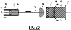
- the release tool 19 comprises an inner rod, provided with a head 34 for holding one end of the implant 10, and a stent 32 slidably mounted coaxially on the rod.
- the release tool 19 further includes an inner sheath 36, slidably mounted relative to the guard 32, an intermediate sheath 24 slidably mounted around the inner sheath 36, and an outer sheath 38 slidably mounted around the intermediate sheath 24.
- the intermediate sheath 24 is the one surrounding the proximal sleeve 14, as described above with reference to the Figures 2 to 4 .
- the holding means 22 comprise a holding sheath 26, as described previously with reference to figures 13 and 14 the intermediate sheath is formed by this holding sheath.
- the release tool 19 may comprise, instead of an intermediate sheath and an outer sheath, only an outer sheath performing the functions of said intermediate sheath and of said outer sheath.
- the guard 32 and the sheaths 36, 24, 38 are slidably movable, independently of one another, and with respect to the rod.
- Locking members are generally provided between the rod and the guard 32, between the guard 32 and the sheaths 36, 24, 38 to prevent the spontaneous sliding of the guard 32, external sheaths 38, intermediate 24 and internal 36 This makes it possible to proceed in successive steps to the withdrawals of the outer sheath 38, of the intermediate sheath 24, of the inner sheath 36.
- the head 34 defines a housing 40 for receiving the implant 10, in which this implant 10 is maintained in contracted configuration.
- the stent 32 and the inner sheath 36 delimit between them an internal annular space 42, intended to receive the distal sleeve 16 and the distal arms 20.
- the distal sleeve 16 is maintained in a configuration contracted by this inner sheath 36.
- the inner sheath 36 and the intermediate sheath 24 delimit between them an intermediate annular space 44, intended to receive the proximal sleeve 14.
- the proximal sleeve 14 is maintained in configuration contracted by this intermediate sheath 24, as described above.
- each proximal arm 18 is pressed against the outer sheath 38 when it is not covered by the sheath intermediate 24, and that the proximal sleeve 14 is in contracted configuration, as shown in FIG. figure 3 .
- the implant 10 When the implant 10 is to be positioned, in particular as a replacement for a native valve, it is introduced between the leaflets 13 of the native valve around the seat of the valve. This introduction can be made using the device of the figure 14 , passing through the left ventricle, as will be described below with reference to Figures 15 to 20 .
- the head 34 and the downstream portion of the tool 19 are introduced into the atrial cavity, beyond the mitral annulus, so that the distal arms 20 are disposed in the atrial cavity beyond the mitral annulus .
- the outer sheath 38 is retracted axially away from the head 34 relative to the intermediate sheath 24, the inner sheath 36 and relative to the guard 32, to discover the distal arms 20, which then deploy.
- the tool 19 is then moved to the left ventricle to press the distal arms 20 against the atrial side of the leaflets 13.
- the outer sheath 38 is further retracted axially to reveal the proximal arms 18. These, which were held pressed against this outer sheath 38, are then deployed under the effect of the constraint imposed by the holding means 22. Indeed, the proximal sleeve 14 is maintained in its contracted configuration, and the proximal arms 18 are not subject to any external stress, so that they are then constrained in their spacing position by the holding means 22, as previously described. .
- the spacing of the proximal arms 18 is then optimally ensured so that the sheets 13 are opposite a reception space 23 defined between these proximal arms 18.
- proximal sleeve 14 and the surrounding sheath 24 surrounding it are thus inserted into the receiving space 23 defined between the proximal arms 18.
- proximal arms 18 extend beyond the distal end 14B of the proximal sleeve 14, this proximal sleeve 14 does not interfere with the insertion of the leaflets 13 into this receiving space 23.
- the inner sheath 36 is retracted to release the distal sleeve 16, as shown in FIG. figure 18 .
- This distal sleeve 16 being disposed inside the proximal sleeve 14, it is maintained in configuration contracted by this proximal sleeve 14, itself maintained in a configuration contracted by the intermediate sheath 24.
- the distal sleeve 16 binds to this proximal sleeve 14.
- proximal sleeves 14 and distal 16 retracts the intermediate sheath 24, so as to release the proximal sleeve 14, as shown in FIG. figure 19 .
- the proximal sleeve 14 then extends radially to its deployed configuration, as well as the distal sleeve 16 within this expanded proximal sleeve 14.
- the holding means 22 release the proximal arms 18, which are then resiliently returned to their anchoring position, as previously described.
- the distal sleeve 16 extends longitudinally, partly inside the proximal sleeve 14, coaxially with this proximal sleeve 14, partly inside the receiving space 23, so that the tissue is received between the proximal arms 18 and the distal sleeve 16, and partly beyond the receiving space 23.
- This deployed configuration corresponds to that of the figure 1 .
- proximal sleeve 14 is arranged axially away from the sheets 13, inside the ventricular cavity.
- the invention can be applied to different proximal arm forms 18
- Said distal portion may also have a domed shape.
- the proximal portion and the bifurcation portion together define a deeper box for the leaflets 13.
- the length of the proximal portion may be chosen more or less important, depending on the desired depth of the box.
- At least one proximal arm 18 has a distal region projecting radially away from the central axis X with respect to an intermediate region of this proximal arm.
- At least one first proximal arm 18 has a first distal region applied opposite a first distal arm 20, and a second proximal arm 18 has a second distal region applied opposite a second distal arm 20, radial extent of the first distal region being greater than the radial extent of the second distal region.
- each proximal arm 18 may be greater or lesser, particularly depending on the predetermined shape of the blood circulation passageway for receiving the implant.
- each proximal arm 18 comprises an elastically deformable intermediate portion in a longitudinal direction of the proximal arm 18.
- the intermediate portion is generally in the form of a spring.
- each proximal arm 18 can vary, and adapt according to the positioning of the proximal sleeve 14 relative to the distal sleeve 16, in particular to ensure optimal pinching of the leaflets 13 between the proximal arms 18 and the distal arms 20.
- each proximal arm 16 has an intermediate portion folded so as to form an axial return defining a cavity. This cavity is intended to form a box for the leaflets 13.
- proximal arms compatible with holding means 22.
- the implant 10 may be installed according to another method of introduction than that described above.
- the different steps of installation of the proximal 14 and distal sleeves 16 may be performed in another order than that described above.
- proximal arms 18 may be previously deployed, the outer sheath 38 being axially retracted to expose these proximal arms 18.
- the proximal sleeve 14 is maintained in its contracted configuration, and the proximal arms 18, which are not subjected to any external stress, are then constrained in their spacing position by the holding means 22, as described above.
- proximal arms 18 The spacing of the proximal arms 18 is then optimally ensured so that the sheets 13 are opposite a reception space 23 defined between these proximal arms 18. It should be noted that starting with the installation of the proximal arms 18, their handling is not hindered by the distal sleeve 16 and the elements for its installation.
- proximal sleeve 14 as well as the surrounding sheath 24 surrounding it, are then moved in the direction of the leaflets 13. These leaflets 13 are thus inserted into the receiving space 23 defined between the proximal arms 18.
- the head 34 and the downstream portion of the tool 19 are then introduced into the atrial cavity, beyond the mitral annulus, so that the distal arms 20 are disposed in the cavity. atrial beyond the mitral ring. In this case, the distal arms 20 are held in the contracted position by the inner sheath 36.
- the inner sheath 36 is then retracted axially away from the head 34 relative to the intermediate sheath 24, and relative to the guard 32, to discover the distal arms 20, which then deploy.
- the tool 19 is then moved to the left ventricle to press the distal arms 20 against the atrial side of the leaflets 13.
- the inner sheath 36 is retracted to release this distal sleeve 16.
- This distal sleeve 16 being disposed inside the proximal sleeve 14, it is maintained in a configuration contracted by this proximal sleeve 14 , itself maintained in configuration contracted by the intermediate sheath 24.
- the distal sleeve 16 binds to this proximal sleeve 14.
- proximal sleeves 14 and distal 16 retracts the intermediate sheath 24, so as to release the proximal sleeve 14.
- the proximal sleeve 14 extends radially to its deployed configuration, and the distal sleeve 16 to the inside of this proximal sleeve 14 deployed.
- the holding means 22 release the proximal arms 18, which are then resiliently returned to their anchoring position, as previously described.
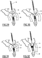
- the delivery method comprises introducing a distal end of the delivery tool 19, including the implant 10 into the contracted configuration, into the cavity ventricular. Then, as shown on the figure 21 the outer sheath 38 is axially retracted to release the proximal arms 18, as previously described. The deployment of the proximal arms 18 defines a reception space 23, which is then completely free.
- proximal arms 18 are deployed before the armature 12 is formed, i.e., before the proximal sleeve 14 is assembled with the distal sleeve 16.
- the inner sheath 36, containing the distal sleeve 16 is moved axially to the atrial cavity, through the mitral annulus, so that the distal arms 20 are positioned in the atrial cavity.
- the inner sheath 36 is retracted axially so as to release the distal arms 20, which are then deployed. During this step, the atrial sleeve 16 remains partially contracted in the inner sheath 36.
- the tool 19 is then moved to the left ventricle to apply the distal arms 20 against the atrial side of the leaflets 13.
- the distal arms 20 apply an axial force against the atrial face of the leaflets 13, this axial force being oriented from the atrial cavity to the ventricular cavity.
- reception space 23 is positioned opposite the sheets 13, so that these sheets 13 are inserted into this reception space 23 when the tool 19 is moved towards these sheets 13, as shown in FIG. figure 25 .
- the proximal arms 18 are applied against the ventricular surface of the leaflets 13.
- the proximal arms 18 apply an axial force against the ventricular face of the leaflets 13, this axial force being oriented from the ventricular cavity to the atrial cavity.
- the direction of the axial force applied by the proximal arms 18 is therefore opposite to the direction of the axial force applied by the distal arms 20.
- the proximal sleeve 14 is axially movable relative to the distal sleeve 16, so that the relative position of the proximal sleeve 14 with respect to the distal sleeve 16 can be selected according to the configuration of the blood circulation passage in which the implant is installed.
- the position of the proximal sleeve 14 is adjusted, then the inner sheath 36 and the outer sheath 38 are retracted, so that the distal sleeve 16 and the proximal sleeve 14 are deployed, as shown in FIG. figure 26 . It should be noted that the distal sleeve 16 and the proximal sleeve 14 can be deployed simultaneously, or alternatively the distal sleeve 16 is deployed inside the proximal sleeve 14 prior to the deployment of this proximal sleeve 14.
- armature 12 is formed only in the deployed configuration.
- the drop tool is removed from the patient.
- proximal sleeve 14 and the distal sleeve 16 forming two separate sets, it is possible to bring them into the blood circulation passage via two separate access routes.
- the distal sleeve 16 can be passed anterograde transvenous, and thus introduced into the atrial cavity without passing through the ventricular cavity, and the proximal sleeve 14 can be brought transaortically retrograde way, and thus introduced into the ventricular cavity without go through the atrial cavity.
- the treatment device comprises a first release tool for the proximal sleeve 14 and a second release tool for the distal sleeve 16.
- first and second drop tools have diameters smaller than the diameter of a release tool carrying both the proximal sleeve 14 and distal 16.
- this method of installation there are two ways of access narrower than the only access path required for the previously described installation methods.
- a first part 19A of the delivery tool comprising an outer sheath 38 and the proximal sleeve 14 in a configuration contracted inside this outer sheath 38, are introduced into the ventricular cavity by a first path.
- a second portion 19B of the delivery tool comprising an inner sheath 36 and the distal sleeve 16 in a configuration contracted within this inner sheath 36, are introduced into the atrial cavity by a second path different from said first pathway.
- the second portion 19B of the delivery tool is not inserted through the mitral annulus into the atrial cavity.
- the outer sheath 38 is then axially retracted so as to release the proximal arms 18, which are thus deployed as previously described.
- the deployment of the proximal arms 18 thus defines the reception space 23.
- the inner sheath 36 containing the distal sleeve 16 is moved axially to the ventricular cavity, beyond the mitral annulus, so that the distal arms 20 remain positioned in the atrial cavity, and that the distal sleeve 16 is positioned partially in the ventricular cavity.
- the inner sheath 36 is retracted axially to release the distal arms 20, which then deploy.
- the distal sleeve 16 remains partially contracted, for example by virtue of an annular holding element 66 surrounding this distal sleeve 16.
- the distal arms 20 are then applied against the atrial side of the leaflets 13, as shown in FIG. figure 30 .
- the distal arms 20 apply an axial force against the atrial side of the leaflets 13, this axial force being oriented from the atrial cavity to the ventricular cavity.
- the receiving space 23 is then positioned facing the sheets 13, so that they are inserted into this receiving space 23 when the first portion 14A of the release tool is moved to these sheets 13, as shown on the figure 31 . Then, the reception space 23 is positioned opposite the sheets 13, so that these sheets 13 are inserted into this reception space 23 when the tool 19 is moved towards these sheets 13, as shown in FIG. figure 25 .
- the proximal arms 18 are applied against the ventricular surface of the leaflets 13.
- the proximal arms 18 apply an axial force against the ventricular face of the leaflets 13, this axial force being oriented from the ventricular cavity to the atrial cavity.
- the direction of the axial force applied by the proximal arms 18 is therefore opposite to the direction of the axial force applied by the distal arms 20.
- the proximal sleeve 14 is axially movable relative to the distal sleeve 16, so that the relative position of the proximal sleeve 14 with respect to the distal sleeve 16 can be selected according to the configuration of the blood circulation passage in which the implant is installed.
- the position of the proximal sleeve 14 is adjusted, then the annular holding member 66 and the outer sheath 38 are retracted, so that the distal sleeve 16 and the proximal sleeve 14 are deployed, as shown in FIG. figure 32 .
- distal sleeve 16 and the proximal sleeve 14 can be deployed simultaneously, or alternatively the distal sleeve 16 is deployed inside the proximal sleeve 14 prior to the deployment of this proximal sleeve 14.
- armature 12 is formed only in the deployed configuration.
- the release tool is removed from the patient, each of its parts through the corresponding path.
Landscapes
- Health & Medical Sciences (AREA)
- Cardiology (AREA)
- Engineering & Computer Science (AREA)
- Biomedical Technology (AREA)
- Heart & Thoracic Surgery (AREA)
- Transplantation (AREA)
- Oral & Maxillofacial Surgery (AREA)
- Vascular Medicine (AREA)
- Life Sciences & Earth Sciences (AREA)
- Animal Behavior & Ethology (AREA)
- General Health & Medical Sciences (AREA)
- Public Health (AREA)
- Veterinary Medicine (AREA)
- Prostheses (AREA)
Claims (10)
- Implantat (10), das dazu bestimmt ist, in einer Blutkreislaufbahn angeordnet zu werden und an einem Gewebe (13) befestigt zu werden, und Folgendes umfasst:- eine proximale Muffe (14) im Allgemeinen in Röhrenform um eine Mittelachse (X), die sich longitudinal zwischen einem proximalen Ende (14A) und einem distalen Ende (14B) erstreckt, wobei die proximale Muffe (14) zwischen einer zusammengezogenen Konfiguration und einer entfalteten Konfiguration entfaltbar ist,- mehrere proximale Arme (18), die sich jeweils zwischen einem ersten Ende (18A), das mit dem distalen Ende (14B) der proximalen Muffe (14) verbunden ist, und einem freien zweiten Ende (18B), das dazu bestimmt ist, sich an einer ersten Fläche des Gewebes (13) abzustützen, erstrecken, wobei sich jeder proximale Arm (18) in Richtung der Mittelachse (X) erstreckt, derart, dass sein freies Ende (18B) jenseits des distalen Endes (14B) der proximalen Muffe (14) angeordnet ist,- eine distale Muffe (16) im Allgemeinen in Röhrenform um die Mittelachse (X), die zwischen einer zusammengezogenen Konfiguration und einer entfalteten Konfiguration entfaltbar ist und dazu bestimmt ist, mit der proximalen Muffe (14) zusammengefügt zu werden, um zusammen eine röhrenförmige Ummantelung (12) zu bilden, wobei diese Ummantelung (12) eine innere Blutkreislaufleitung definiert, wenn die proximale Muffe (14) und die distale Muffe (16) zusammengefügt sind und jede von ihnen in der entfalteten Konfiguration ist,- mehrere distale Arme (20), die von der distalen Muffe (16) getragen werden und die sich in der entfalteten Konfiguration im Wesentlichen senkrecht zu der Mittelachse (X) erstrecken und dazu bestimmt sind, sich an einer zweiten Fläche des Gewebes (13) abzustützen, derart, dass das Gewebe (13) dann zwischen den proximalen Armen (18) und den distalen Armen (20) eingeklemmt ist,dadurch gekennzeichnet, dass:- wenigstens ein proximaler Arm (18) zwischen einer beabstandeten Position und einer Verankerungsposition elastisch verformbar ist, derart, dass bei Abwesenheit einer äußeren Kraft der radiale Abstand zwischen seinem freien Ende (18B) und seinem verbundenen Ende (18A) in der beabstandeten Position größer als in der Verankerungsposition ist, wobei dieser proximale Arm (18) in seine Verankerungsposition elastisch zurückgestellt wird,- das Implantat (10) Mittel (22) zum Halten des wenigstens einen verformbaren proximalen Arms (18) in seiner beabstandeten Position umfasst, die ihrerseits umfassen:• einen ersten Anschlag (22A), der von diesem proximalen Arm (18) getragen wird, und• einen zweiten Anschlag (22B), der dazu bestimmt ist, mit dem ersten Anschlag (22A) zusammenzuwirken, wenn die proximale Muffe (14) in der zusammengezogenen Konfiguration ist, um diesen proximalen Arm (18) in seiner beabstandeten Position zu halten, und diesen ersten Anschlag (22A) freizugeben, wenn die proximale Muffe (14) in der entfalteten Konfiguration ist, damit sich der proximale Arm (18) in seine Verankerungsposition verlagern kann.
- Implantat (10) nach Anspruch 1, wobei sich der erste Anschlag (22A) des proximalen Arms (18) seitlich in Bezug auf diesen proximalen Arm (18) erstreckt, wobei dieser erste Anschlag (22A) vorzugsweise in der Nähe des verbundenen Endes (18A) dieses proximalen Arms (18) angeordnet ist.
- Implantat (10) nach Anspruch 1 oder 2, wobei der zweite Anschlag (22B) von der proximalen Muffe (14) getragen wird.
- Implantat (10) nach Anspruch 3, wobei die proximale Muffe (14) aus gitterförmig angeordneten drahtförmigen Elementen (15) gebildet ist, die Maschen (M) beispielsweise in Rautenform bilden, wobei jeder proximale Arm (18), der mit einem ersten Anschlag (22A) versehen ist, in Umfangsrichtung auf der proximalen Muffe (14) zwischen zwei aufeinanderfolgenden Maschen (M) angeordnet ist, wobei der entsprechende zweite Anschlag (22B) von wenigstens einem der drahtförmigen Elemente (15), die diese zwei aufeinanderfolgenden Maschen (M) bilden, getragen wird, wobei diese drahtförmigen Elemente (15) in der zusammengezogenen Konfiguration einander angenähert sind, derart, dass der zweite Anschlag (22B) mit dem ersten Anschlag (22A) zusammenwirkt, und in der entfalteten Konfiguration voneinander entfernt sind, derart, dass ein radialer Durchlass für den ersten Anschlag (22A) frei bleibt, wodurch dieser erste Anschlag (22A) freigegeben wird.
- Implantat (10) nach einem der vorhergehenden Ansprüche, wobei die proximale Muffe (14) wenigstens zwei proximale Arme (18) trägt, wovon jeder mit einem ersten Anschlag (22A) versehen ist, derart, dass der Abstand zwischen dem ersten Anschlag (22A) und dem verbundenen Ende (18A) eines dieser zwei proximalen Arme (18) größer als der Abstand zwischen dem ersten Anschlag (22A) und dem verbundenen Ende (18A) des anderen dieser zwei proximalen Arme (18) ist.
- Implantat (10) nach einem der Ansprüche 1 bis 5, wobei der erste Anschlag (22A) wenigstens eines der proximalen Arme (18) durch einen vorstehenden Teil dieses proximalen Arms (18) gebildet ist und sich in Bezug auf diesen proximalen Arm (18) seitlich erstreckt.
- Implantat (10) nach einem der Ansprüche 1 bis 5, wobei der erste Anschlag (22A) wenigstens eines der proximalen Arme (18) durch Element (25) gebildet ist, das an diesem proximalen Arm (18) beispielsweise durch Schweißen angefügt ist, wobei sich dieses Element (25) seitlich in Bezug auf diesen proximalen Arm (18) erstreckt.
- Vorrichtung zum Bearbeiten eines Blutkreislaufdurchlasses, gekennzeichnet durch:- ein Implantat (10) nach einem der vorhergehenden Ansprüche; und- ein Werkzeug (19) zum Ausgeben des Implantats (10), wobei die proximale Muffe (14) und die distale Muffe (16) in dem Ausgabewerkzeug (19) in ihren zusammengezogenen Konfigurationen montiert sind.
- Bearbeitungsvorrichtung nach Anspruch 8, wobei:- das Ausgabewerkzeug (19) eine Hülse (26) umfasst, um jeden proximalen Arm (18), der mit einem ersten Anschlag (22A) versehen ist, in seiner beabstandeten Position zu halten, und- die Haltehülse (26) eine im allgemeinen rotationssymmetrische Form um die Längsachse (X) aufweist und dazu bestimmt ist, um die proximale Muffe (18) in der zusammengezogenen Konfiguration angeordnet zu werden,- die Haltehülse (26) longitudinale Bänder (30) aufweist, die durch longitudinale Öffnungen (28) getrennt sind, wobei jedes longitudinale Band (30) dazu bestimmt ist, sich durch eine in einem jeweiligen proximalen Arm (18) vorgesehene Öffnung zu bewegen,- jedes longitudinale Band (30) einen zweiten Anschlag (22B) aufweist, der dazu bestimmt ist, mit dem ersten Anschlag (22A) des proximalen Arms (18), durch den sich dieses longitudinale Band (30) bewegt, zusammenzuwirken.
- Bearbeitungsvorrichtung nach Anspruch 9, wobei das longitudinale Band (30) mit einer Erhebung versehen ist, die radial in die äußere Umgebung der Haltehülse (26) vorsteht und den zweiten Anschlag (22B) trägt.
Applications Claiming Priority (2)
| Application Number | Priority Date | Filing Date | Title |
|---|---|---|---|
| FR1353605A FR3004638B1 (fr) | 2013-04-19 | 2013-04-19 | Implant, notamment destine a etre place dans une valve auriculo-ventriculaire cardiaque, comportant un systeme d'ecartement des bras proximaux |
| PCT/EP2014/057972 WO2014170463A1 (fr) | 2013-04-19 | 2014-04-17 | Implant, destiné à être placé dans un passage de circulation de sang, comportant un système d'écartement des bras proximaux |
Publications (2)
| Publication Number | Publication Date |
|---|---|
| EP2986255A1 EP2986255A1 (de) | 2016-02-24 |
| EP2986255B1 true EP2986255B1 (de) | 2017-01-25 |
Family
ID=48614005
Family Applications (1)
| Application Number | Title | Priority Date | Filing Date |
|---|---|---|---|
| EP14721266.6A Not-in-force EP2986255B1 (de) | 2013-04-19 | 2014-04-17 | Implantate zum einsatz in einer blutzirkulationspassage mit einem system zum trennen der proximalen arme |
Country Status (4)
| Country | Link |
|---|---|
| US (1) | US10058418B2 (de) |
| EP (1) | EP2986255B1 (de) |
| FR (1) | FR3004638B1 (de) |
| WO (1) | WO2014170463A1 (de) |
Cited By (16)
| Publication number | Priority date | Publication date | Assignee | Title |
|---|---|---|---|---|
| US10856984B2 (en) | 2017-08-25 | 2020-12-08 | Neovasc Tiara Inc. | Sequentially deployed transcatheter mitral valve prosthesis |
| US10940001B2 (en) | 2012-05-30 | 2021-03-09 | Neovasc Tiara Inc. | Methods and apparatus for loading a prosthesis onto a delivery system |
| US11311376B2 (en) | 2019-06-20 | 2022-04-26 | Neovase Tiara Inc. | Low profile prosthetic mitral valve |
| US11357622B2 (en) | 2016-01-29 | 2022-06-14 | Neovase Tiara Inc. | Prosthetic valve for avoiding obstruction of outflow |
| US11389291B2 (en) | 2013-04-04 | 2022-07-19 | Neovase Tiara Inc. | Methods and apparatus for delivering a prosthetic valve to a beating heart |
| US11413139B2 (en) | 2011-11-23 | 2022-08-16 | Neovasc Tiara Inc. | Sequentially deployed transcatheter mitral valve prosthesis |
| US11419720B2 (en) | 2010-05-05 | 2022-08-23 | Neovasc Tiara Inc. | Transcatheter mitral valve prosthesis |
| US11464631B2 (en) | 2016-11-21 | 2022-10-11 | Neovasc Tiara Inc. | Methods and systems for rapid retraction of a transcatheter heart valve delivery system |
| US11491006B2 (en) | 2019-04-10 | 2022-11-08 | Neovasc Tiara Inc. | Prosthetic valve with natural blood flow |
| US11497602B2 (en) | 2012-02-14 | 2022-11-15 | Neovasc Tiara Inc. | Methods and apparatus for engaging a valve prosthesis with tissue |
| US11602429B2 (en) | 2019-04-01 | 2023-03-14 | Neovasc Tiara Inc. | Controllably deployable prosthetic valve |
| US11737872B2 (en) | 2018-11-08 | 2023-08-29 | Neovasc Tiara Inc. | Ventricular deployment of a transcatheter mitral valve prosthesis |
| US11779742B2 (en) | 2019-05-20 | 2023-10-10 | Neovasc Tiara Inc. | Introducer with hemostasis mechanism |
| US11998447B2 (en) | 2019-03-08 | 2024-06-04 | Neovasc Tiara Inc. | Retrievable prosthesis delivery system |
| US12109111B2 (en) | 2015-12-15 | 2024-10-08 | Neovasc Tiara Inc. | Transseptal delivery system |
| US12611303B2 (en) | 2022-07-21 | 2026-04-28 | Neovasc Tiara Inc. | Transcatheter mitral valve prosthesis |
Families Citing this family (55)
| Publication number | Priority date | Publication date | Assignee | Title |
|---|---|---|---|---|
| US8870950B2 (en) | 2009-12-08 | 2014-10-28 | Mitral Tech Ltd. | Rotation-based anchoring of an implant |
| US20110224785A1 (en) | 2010-03-10 | 2011-09-15 | Hacohen Gil | Prosthetic mitral valve with tissue anchors |
| US9763657B2 (en) | 2010-07-21 | 2017-09-19 | Mitraltech Ltd. | Techniques for percutaneous mitral valve replacement and sealing |
| US11653910B2 (en) | 2010-07-21 | 2023-05-23 | Cardiovalve Ltd. | Helical anchor implantation |
| US20140324164A1 (en) | 2011-08-05 | 2014-10-30 | Mitraltech Ltd. | Techniques for percutaneous mitral valve replacement and sealing |
| WO2013021374A2 (en) | 2011-08-05 | 2013-02-14 | Mitraltech Ltd. | Techniques for percutaneous mitral valve replacement and sealing |
| US8852272B2 (en) | 2011-08-05 | 2014-10-07 | Mitraltech Ltd. | Techniques for percutaneous mitral valve replacement and sealing |
| WO2013021375A2 (en) | 2011-08-05 | 2013-02-14 | Mitraltech Ltd. | Percutaneous mitral valve replacement and sealing |
| US20150351906A1 (en) | 2013-01-24 | 2015-12-10 | Mitraltech Ltd. | Ventricularly-anchored prosthetic valves |
| EP3174502B1 (de) | 2014-07-30 | 2022-04-06 | Cardiovalve Ltd | Vorrichtung zur implantation einer knickbaren klappenprothese |
| EP3253333B1 (de) | 2015-02-05 | 2024-04-03 | Cardiovalve Ltd | Klappenprothese mit axial gleitendem rahmen |
| US9974651B2 (en) | 2015-02-05 | 2018-05-22 | Mitral Tech Ltd. | Prosthetic valve with axially-sliding frames |
| US10456243B2 (en) * | 2015-10-09 | 2019-10-29 | Medtronic Vascular, Inc. | Heart valves prostheses and methods for percutaneous heart valve replacement |
| CA3006010C (en) * | 2015-12-28 | 2023-09-26 | Tendyne Holdings, Inc. | Atrial pocket closures for prosthetic heart valves |
| US10531866B2 (en) | 2016-02-16 | 2020-01-14 | Cardiovalve Ltd. | Techniques for providing a replacement valve and transseptal communication |
| US20190231525A1 (en) | 2016-08-01 | 2019-08-01 | Mitraltech Ltd. | Minimally-invasive delivery systems |
| USD800908S1 (en) | 2016-08-10 | 2017-10-24 | Mitraltech Ltd. | Prosthetic valve element |
| ES3018641T3 (es) | 2016-08-10 | 2025-05-16 | Cardiovalve Ltd | Válvula protésica con marcos concéntricos |
| EP3525725B1 (de) | 2016-10-13 | 2024-04-24 | Boston Scientific Scimed, Inc. | Künstliche herzklappe mit membran |
| CN106618798B (zh) * | 2016-10-24 | 2019-10-11 | 宁波健世生物科技有限公司 | 一种通过室间隔固定的心脏瓣膜假体及其输送和释放方法 |
| FR3058632B1 (fr) | 2016-11-14 | 2019-01-25 | Laboratoires Invalv | Dispositif de traitement d'une valve biologique avec organe de poussee de la valve |
| FR3058631B1 (fr) * | 2016-11-14 | 2019-01-25 | Laboratoires Invalv | Implant de traitement d'une valve biologique |
| US10653523B2 (en) | 2017-01-19 | 2020-05-19 | 4C Medical Technologies, Inc. | Systems, methods and devices for delivery systems, methods and devices for implanting prosthetic heart valves |
| US10561495B2 (en) | 2017-01-24 | 2020-02-18 | 4C Medical Technologies, Inc. | Systems, methods and devices for two-step delivery and implantation of prosthetic heart valve |
| US12029647B2 (en) | 2017-03-07 | 2024-07-09 | 4C Medical Technologies, Inc. | Systems, methods and devices for prosthetic heart valve with single valve leaflet |
| US12036113B2 (en) | 2017-06-14 | 2024-07-16 | 4C Medical Technologies, Inc. | Delivery of heart chamber prosthetic valve implant |
| US12064347B2 (en) | 2017-08-03 | 2024-08-20 | Cardiovalve Ltd. | Prosthetic heart valve |
| US10575948B2 (en) | 2017-08-03 | 2020-03-03 | Cardiovalve Ltd. | Prosthetic heart valve |
| US10888421B2 (en) | 2017-09-19 | 2021-01-12 | Cardiovalve Ltd. | Prosthetic heart valve with pouch |
| US11246704B2 (en) | 2017-08-03 | 2022-02-15 | Cardiovalve Ltd. | Prosthetic heart valve |
| US10537426B2 (en) | 2017-08-03 | 2020-01-21 | Cardiovalve Ltd. | Prosthetic heart valve |
| US11793633B2 (en) | 2017-08-03 | 2023-10-24 | Cardiovalve Ltd. | Prosthetic heart valve |
| US10905549B2 (en) | 2017-09-19 | 2021-02-02 | Cardiovalve Ltd. | Prosthetic valve with overlapping atrial tissue anchors and ventricular tissue anchors |
| US12458493B2 (en) | 2017-09-19 | 2025-11-04 | Cardiovalve Ltd. | Prosthetic heart valve and delivery systems and methods |
| US9895226B1 (en) | 2017-10-19 | 2018-02-20 | Mitral Tech Ltd. | Techniques for use with prosthetic valve leaflets |
| GB201720803D0 (en) | 2017-12-13 | 2018-01-24 | Mitraltech Ltd | Prosthetic Valve and delivery tool therefor |
| GB201800399D0 (en) | 2018-01-10 | 2018-02-21 | Mitraltech Ltd | Temperature-control during crimping of an implant |
| EP4541293A3 (de) | 2018-02-08 | 2025-07-16 | Invalve Therapeutics, Inc. | Vorrichtung zur behandlung von blutflussregurgitation durch eine native herzklappe |
| US11857441B2 (en) | 2018-09-04 | 2024-01-02 | 4C Medical Technologies, Inc. | Stent loading device |
| US12121436B2 (en) * | 2018-12-04 | 2024-10-22 | Medtronic Bakken Research Center B.V. | Prosthetic heart valve |
| GB201901887D0 (en) | 2019-02-11 | 2019-04-03 | Cardiovalve Ltd | Device for conditioning ex vivo pericardial tissue |
| US12544226B2 (en) | 2019-02-14 | 2026-02-10 | 4C Medical Technologies, Inc. | Hydrophilic skirt for paravalvular leak mitigation and fit and apposition optimization for prosthetic heart valve implants |
| EP3946162A4 (de) * | 2019-03-25 | 2023-04-19 | Inqb8 Medical Technologies, LLC | Herzklappenprothese |
| US11452628B2 (en) | 2019-04-15 | 2022-09-27 | 4C Medical Technologies, Inc. | Loading systems for collapsible prosthetic heart valve devices and methods thereof |
| CN113017951B (zh) * | 2019-12-24 | 2025-08-12 | 上海微创心通医疗科技有限公司 | 一种植入体输送装置及其内管组件、导管 |
| US11931253B2 (en) | 2020-01-31 | 2024-03-19 | 4C Medical Technologies, Inc. | Prosthetic heart valve delivery system: ball-slide attachment |
| US12133797B2 (en) | 2020-01-31 | 2024-11-05 | 4C Medical Technologies, Inc. | Prosthetic heart valve delivery system: paddle attachment feature |
| US12053375B2 (en) | 2020-03-05 | 2024-08-06 | 4C Medical Technologies, Inc. | Prosthetic mitral valve with improved atrial and/or annular apposition and paravalvular leakage mitigation |
| US11992403B2 (en) | 2020-03-06 | 2024-05-28 | 4C Medical Technologies, Inc. | Devices, systems and methods for improving recapture of prosthetic heart valve device with stent frame having valve support with inwardly stent cells |
| EP4203859A4 (de) | 2020-08-28 | 2024-09-25 | Inqb8 Medical Technologies, LLC | Herzklappenprothese |
| US12357459B2 (en) | 2020-12-03 | 2025-07-15 | Cardiovalve Ltd. | Transluminal delivery system |
| WO2023062551A1 (en) | 2021-10-12 | 2023-04-20 | Laguna Tech Usa, Inc. | Prosthesis heart valve device, delivery system, interventional system and relate method |
| US12594164B1 (en) | 2022-09-01 | 2026-04-07 | 4C Medical Technologies, Inc. | Prosthetic heart valve for natural blood flow |
| US20240366366A1 (en) | 2023-03-24 | 2024-11-07 | 4C Medical Technologies, Inc. | Implant delivery |
| CN119499013B (zh) * | 2024-10-18 | 2026-01-02 | 上海以心医疗器械有限公司 | 瓣膜支架及瓣膜假体 |
Family Cites Families (5)
| Publication number | Priority date | Publication date | Assignee | Title |
|---|---|---|---|---|
| EP2205183B1 (de) * | 2007-10-25 | 2018-11-28 | Symetis SA | Ein system zum ersetzen einer herzklappe |
| AU2010236288A1 (en) | 2009-04-15 | 2011-10-20 | Cardiaq Valve Technologies, Inc. | Vascular implant and delivery system |
| CA2779393C (en) | 2009-11-05 | 2020-06-09 | The Trustees Of The University Of Pennsylvania | Valve prosthesis |
| EP3061422B1 (de) * | 2010-06-21 | 2021-11-03 | Edwards Lifesciences CardiAQ LLC | Herzklappenersatz |
| FR2982763B1 (fr) * | 2011-11-17 | 2015-07-17 | Ct Hospitalier Regional Universitaire D Amiens | Implant destine a etre place dans un passage de circulation du sang et dispositif de traitement associe |
-
2013
- 2013-04-19 FR FR1353605A patent/FR3004638B1/fr active Active
-
2014
- 2014-04-17 US US14/785,208 patent/US10058418B2/en not_active Expired - Fee Related
- 2014-04-17 WO PCT/EP2014/057972 patent/WO2014170463A1/fr not_active Ceased
- 2014-04-17 EP EP14721266.6A patent/EP2986255B1/de not_active Not-in-force
Non-Patent Citations (1)
| Title |
|---|
| None * |
Cited By (25)
| Publication number | Priority date | Publication date | Assignee | Title |
|---|---|---|---|---|
| US11419720B2 (en) | 2010-05-05 | 2022-08-23 | Neovasc Tiara Inc. | Transcatheter mitral valve prosthesis |
| US11413139B2 (en) | 2011-11-23 | 2022-08-16 | Neovasc Tiara Inc. | Sequentially deployed transcatheter mitral valve prosthesis |
| US12053369B2 (en) | 2011-11-23 | 2024-08-06 | Neovasc Tiara Inc. | Sequentially deployed transcatheter mitral valve prosthesis |
| US12138159B2 (en) | 2012-02-14 | 2024-11-12 | Neovasc Tiara Inc. | Methods and apparatus for engaging a valve prosthesis with tissue |
| US11497602B2 (en) | 2012-02-14 | 2022-11-15 | Neovasc Tiara Inc. | Methods and apparatus for engaging a valve prosthesis with tissue |
| US11617650B2 (en) | 2012-05-30 | 2023-04-04 | Neovasc Tiara Inc. | Methods and apparatus for loading a prosthesis onto a delivery system |
| US11389294B2 (en) | 2012-05-30 | 2022-07-19 | Neovasc Tiara Inc. | Methods and apparatus for loading a prosthesis onto a delivery system |
| US10940001B2 (en) | 2012-05-30 | 2021-03-09 | Neovasc Tiara Inc. | Methods and apparatus for loading a prosthesis onto a delivery system |
| US11389291B2 (en) | 2013-04-04 | 2022-07-19 | Neovase Tiara Inc. | Methods and apparatus for delivering a prosthetic valve to a beating heart |
| US12109111B2 (en) | 2015-12-15 | 2024-10-08 | Neovasc Tiara Inc. | Transseptal delivery system |
| US12193932B2 (en) | 2016-01-29 | 2025-01-14 | Neovasc Tiara Inc. | Prosthetic valve for avoiding obstruction of outflow |
| US11357622B2 (en) | 2016-01-29 | 2022-06-14 | Neovase Tiara Inc. | Prosthetic valve for avoiding obstruction of outflow |
| US11464631B2 (en) | 2016-11-21 | 2022-10-11 | Neovasc Tiara Inc. | Methods and systems for rapid retraction of a transcatheter heart valve delivery system |
| US12201524B2 (en) | 2016-11-21 | 2025-01-21 | Neovasc Tiara Inc. | Methods and systems for rapid retraction of a transcatheter heart valve delivery system |
| US10856984B2 (en) | 2017-08-25 | 2020-12-08 | Neovasc Tiara Inc. | Sequentially deployed transcatheter mitral valve prosthesis |
| US11793640B2 (en) | 2017-08-25 | 2023-10-24 | Neovasc Tiara Inc. | Sequentially deployed transcatheter mitral valve prosthesis |
| US11737872B2 (en) | 2018-11-08 | 2023-08-29 | Neovasc Tiara Inc. | Ventricular deployment of a transcatheter mitral valve prosthesis |
| US11998447B2 (en) | 2019-03-08 | 2024-06-04 | Neovasc Tiara Inc. | Retrievable prosthesis delivery system |
| US11602429B2 (en) | 2019-04-01 | 2023-03-14 | Neovasc Tiara Inc. | Controllably deployable prosthetic valve |
| US12036117B2 (en) | 2019-04-10 | 2024-07-16 | Neovasc Tiara Inc. | Prosthetic valve with natural blood flow |
| US11491006B2 (en) | 2019-04-10 | 2022-11-08 | Neovasc Tiara Inc. | Prosthetic valve with natural blood flow |
| US11779742B2 (en) | 2019-05-20 | 2023-10-10 | Neovasc Tiara Inc. | Introducer with hemostasis mechanism |
| US11311376B2 (en) | 2019-06-20 | 2022-04-26 | Neovase Tiara Inc. | Low profile prosthetic mitral valve |
| US11931254B2 (en) | 2019-06-20 | 2024-03-19 | Neovasc Tiara Inc. | Low profile prosthetic mitral valve |
| US12611303B2 (en) | 2022-07-21 | 2026-04-28 | Neovasc Tiara Inc. | Transcatheter mitral valve prosthesis |
Also Published As
| Publication number | Publication date |
|---|---|
| EP2986255A1 (de) | 2016-02-24 |
| US10058418B2 (en) | 2018-08-28 |
| US20160095700A1 (en) | 2016-04-07 |
| FR3004638A1 (fr) | 2014-10-24 |
| WO2014170463A1 (fr) | 2014-10-23 |
| FR3004638B1 (fr) | 2015-05-29 |
Similar Documents
| Publication | Publication Date | Title |
|---|---|---|
| EP2986255B1 (de) | Implantate zum einsatz in einer blutzirkulationspassage mit einem system zum trennen der proximalen arme | |
| EP2779943B1 (de) | Implantat zur positionierung in einem blutflussdurchgang und entsprechende behandlungsvorrichtung | |
| FR3058631A1 (fr) | Implant de traitement d'une valve biologique | |
| FR3058632A1 (fr) | Dispositif de traitement d'une valve biologique avec organe de poussee de la valve | |
| EP2266504B1 (de) | Verfahren und Vorrichtung zum Einsetzen von Endoprothesen | |
| EP2000116B1 (de) | Kit zum Implantieren in eine Blutkreislaufbahn | |
| FR3020265B1 (fr) | Dispositif de mise en place d'une etancheite autour d'un implant dans un passage de circulation du sang, et necessaire de traitement associe | |
| EP1411865B1 (de) | Anordnung zum einsetzen einer ventilprothese in ein körpergefäss | |
| FR3006884A1 (fr) | Dispositif atraumatique d'introduction d'un element tubulaire creux dans un organe biologique | |
| EP3554423B1 (de) | Vorrichtung zur durchführung oder vorbereitung einer mitralklappenanuloplastik durch einen transfemoralen ansatz | |
| WO2012035279A1 (fr) | Implant destine a être place dans un passage sanguin auriculo-ventriculaire | |
| FR3023703A1 (fr) | Dispositif de traitement d'un conduit de circulation du sang | |
| WO2014064174A1 (fr) | Dispositif de mise en place d'une étanchéité autour d'un implant dans un passage de circulation du sang, et nécessaire de traitement associé | |
| EP3169277A1 (de) | Vorrichtung zur endovaskulären behandlung einer herzklappe bei der vorbereitung für einen perkutanen klappenersatz | |
| FR3027212A1 (fr) | Implant intervalvulaire pour valve mitrale | |
| FR2906454A1 (fr) | Implant destine a etre place dans un conduit de circulation du sang. | |
| FR2910269A1 (fr) | Materiel de traitement d'une valve cardiaque,en particulier d'une valve mitrale | |
| EP3796953B1 (de) | Vorrichtung zur verankerung einer herzpumpe | |
| EP4403137A1 (de) | System zur befestigung eines herzklappenventils an einer herzprothese und herzprothese mit einem solchen befestigungssystem. | |
| EP3796852B1 (de) | Coring-vorrichtung und coring- und einführungsanordnung mit solch einer vorrichtung | |
| FR3079409A1 (fr) | Systeme de traitement d'une valve cardiaque, en particulier une valve mitrale ou tricuspide | |
| FR2798283A1 (fr) | Couche-culotte a fermeture par systeme d'attache mecanique a emboitement |
Legal Events
| Date | Code | Title | Description |
|---|---|---|---|
| PUAI | Public reference made under article 153(3) epc to a published international application that has entered the european phase |
Free format text: ORIGINAL CODE: 0009012 |
|
| 17P | Request for examination filed |
Effective date: 20151119 |
|
| AK | Designated contracting states |
Kind code of ref document: A1 Designated state(s): AL AT BE BG CH CY CZ DE DK EE ES FI FR GB GR HR HU IE IS IT LI LT LU LV MC MK MT NL NO PL PT RO RS SE SI SK SM TR |
|
| AX | Request for extension of the european patent |
Extension state: BA ME |
|
| RIN1 | Information on inventor provided before grant (corrected) |
Inventor name: RIGHINI, GIOVANNI |
|
| DAX | Request for extension of the european patent (deleted) | ||
| GRAP | Despatch of communication of intention to grant a patent |
Free format text: ORIGINAL CODE: EPIDOSNIGR1 |
|
| INTG | Intention to grant announced |
Effective date: 20160830 |
|
| GRAS | Grant fee paid |
Free format text: ORIGINAL CODE: EPIDOSNIGR3 |
|
| GRAA | (expected) grant |
Free format text: ORIGINAL CODE: 0009210 |
|
| AK | Designated contracting states |
Kind code of ref document: B1 Designated state(s): AL AT BE BG CH CY CZ DE DK EE ES FI FR GB GR HR HU IE IS IT LI LT LU LV MC MK MT NL NO PL PT RO RS SE SI SK SM TR |
|
| REG | Reference to a national code |
Ref country code: GB Ref legal event code: FG4D Free format text: NOT ENGLISH |
|
| REG | Reference to a national code |
Ref country code: CH Ref legal event code: EP |
|
| REG | Reference to a national code |
Ref country code: AT Ref legal event code: REF Ref document number: 863670 Country of ref document: AT Kind code of ref document: T Effective date: 20170215 |
|
| REG | Reference to a national code |
Ref country code: IE Ref legal event code: FG4D Free format text: LANGUAGE OF EP DOCUMENT: FRENCH |
|
| REG | Reference to a national code |
Ref country code: FR Ref legal event code: PLFP Year of fee payment: 4 |
|
| REG | Reference to a national code |
Ref country code: DE Ref legal event code: R096 Ref document number: 602014006388 Country of ref document: DE |
|
| REG | Reference to a national code |
Ref country code: LT Ref legal event code: MG4D |
|
| REG | Reference to a national code |
Ref country code: NL Ref legal event code: MP Effective date: 20170125 |
|
| REG | Reference to a national code |
Ref country code: AT Ref legal event code: MK05 Ref document number: 863670 Country of ref document: AT Kind code of ref document: T Effective date: 20170125 |
|
| PG25 | Lapsed in a contracting state [announced via postgrant information from national office to epo] |
Ref country code: NL Free format text: LAPSE BECAUSE OF FAILURE TO SUBMIT A TRANSLATION OF THE DESCRIPTION OR TO PAY THE FEE WITHIN THE PRESCRIBED TIME-LIMIT Effective date: 20170125 |
|
| PG25 | Lapsed in a contracting state [announced via postgrant information from national office to epo] |
Ref country code: HR Free format text: LAPSE BECAUSE OF FAILURE TO SUBMIT A TRANSLATION OF THE DESCRIPTION OR TO PAY THE FEE WITHIN THE PRESCRIBED TIME-LIMIT Effective date: 20170125 Ref country code: LT Free format text: LAPSE BECAUSE OF FAILURE TO SUBMIT A TRANSLATION OF THE DESCRIPTION OR TO PAY THE FEE WITHIN THE PRESCRIBED TIME-LIMIT Effective date: 20170125 Ref country code: FI Free format text: LAPSE BECAUSE OF FAILURE TO SUBMIT A TRANSLATION OF THE DESCRIPTION OR TO PAY THE FEE WITHIN THE PRESCRIBED TIME-LIMIT Effective date: 20170125 Ref country code: NO Free format text: LAPSE BECAUSE OF FAILURE TO SUBMIT A TRANSLATION OF THE DESCRIPTION OR TO PAY THE FEE WITHIN THE PRESCRIBED TIME-LIMIT Effective date: 20170425 Ref country code: GR Free format text: LAPSE BECAUSE OF FAILURE TO SUBMIT A TRANSLATION OF THE DESCRIPTION OR TO PAY THE FEE WITHIN THE PRESCRIBED TIME-LIMIT Effective date: 20170426 Ref country code: IS Free format text: LAPSE BECAUSE OF FAILURE TO SUBMIT A TRANSLATION OF THE DESCRIPTION OR TO PAY THE FEE WITHIN THE PRESCRIBED TIME-LIMIT Effective date: 20170525 |
|
| PG25 | Lapsed in a contracting state [announced via postgrant information from national office to epo] |
Ref country code: AT Free format text: LAPSE BECAUSE OF FAILURE TO SUBMIT A TRANSLATION OF THE DESCRIPTION OR TO PAY THE FEE WITHIN THE PRESCRIBED TIME-LIMIT Effective date: 20170125 Ref country code: RS Free format text: LAPSE BECAUSE OF FAILURE TO SUBMIT A TRANSLATION OF THE DESCRIPTION OR TO PAY THE FEE WITHIN THE PRESCRIBED TIME-LIMIT Effective date: 20170125 Ref country code: BG Free format text: LAPSE BECAUSE OF FAILURE TO SUBMIT A TRANSLATION OF THE DESCRIPTION OR TO PAY THE FEE WITHIN THE PRESCRIBED TIME-LIMIT Effective date: 20170425 Ref country code: SE Free format text: LAPSE BECAUSE OF FAILURE TO SUBMIT A TRANSLATION OF THE DESCRIPTION OR TO PAY THE FEE WITHIN THE PRESCRIBED TIME-LIMIT Effective date: 20170125 Ref country code: ES Free format text: LAPSE BECAUSE OF FAILURE TO SUBMIT A TRANSLATION OF THE DESCRIPTION OR TO PAY THE FEE WITHIN THE PRESCRIBED TIME-LIMIT Effective date: 20170125 Ref country code: PT Free format text: LAPSE BECAUSE OF FAILURE TO SUBMIT A TRANSLATION OF THE DESCRIPTION OR TO PAY THE FEE WITHIN THE PRESCRIBED TIME-LIMIT Effective date: 20170525 Ref country code: PL Free format text: LAPSE BECAUSE OF FAILURE TO SUBMIT A TRANSLATION OF THE DESCRIPTION OR TO PAY THE FEE WITHIN THE PRESCRIBED TIME-LIMIT Effective date: 20170125 Ref country code: LV Free format text: LAPSE BECAUSE OF FAILURE TO SUBMIT A TRANSLATION OF THE DESCRIPTION OR TO PAY THE FEE WITHIN THE PRESCRIBED TIME-LIMIT Effective date: 20170125 |
|
| REG | Reference to a national code |
Ref country code: DE Ref legal event code: R097 Ref document number: 602014006388 Country of ref document: DE |
|
| PG25 | Lapsed in a contracting state [announced via postgrant information from national office to epo] |
Ref country code: RO Free format text: LAPSE BECAUSE OF FAILURE TO SUBMIT A TRANSLATION OF THE DESCRIPTION OR TO PAY THE FEE WITHIN THE PRESCRIBED TIME-LIMIT Effective date: 20170125 Ref country code: IT Free format text: LAPSE BECAUSE OF FAILURE TO SUBMIT A TRANSLATION OF THE DESCRIPTION OR TO PAY THE FEE WITHIN THE PRESCRIBED TIME-LIMIT Effective date: 20170125 Ref country code: SK Free format text: LAPSE BECAUSE OF FAILURE TO SUBMIT A TRANSLATION OF THE DESCRIPTION OR TO PAY THE FEE WITHIN THE PRESCRIBED TIME-LIMIT Effective date: 20170125 Ref country code: EE Free format text: LAPSE BECAUSE OF FAILURE TO SUBMIT A TRANSLATION OF THE DESCRIPTION OR TO PAY THE FEE WITHIN THE PRESCRIBED TIME-LIMIT Effective date: 20170125 Ref country code: CZ Free format text: LAPSE BECAUSE OF FAILURE TO SUBMIT A TRANSLATION OF THE DESCRIPTION OR TO PAY THE FEE WITHIN THE PRESCRIBED TIME-LIMIT Effective date: 20170125 |
|
| PG25 | Lapsed in a contracting state [announced via postgrant information from national office to epo] |
Ref country code: DK Free format text: LAPSE BECAUSE OF FAILURE TO SUBMIT A TRANSLATION OF THE DESCRIPTION OR TO PAY THE FEE WITHIN THE PRESCRIBED TIME-LIMIT Effective date: 20170125 Ref country code: SM Free format text: LAPSE BECAUSE OF FAILURE TO SUBMIT A TRANSLATION OF THE DESCRIPTION OR TO PAY THE FEE WITHIN THE PRESCRIBED TIME-LIMIT Effective date: 20170125 |
|
| REG | Reference to a national code |
Ref country code: CH Ref legal event code: PL |
|
| PLBE | No opposition filed within time limit |
Free format text: ORIGINAL CODE: 0009261 |
|
| STAA | Information on the status of an ep patent application or granted ep patent |
Free format text: STATUS: NO OPPOSITION FILED WITHIN TIME LIMIT |
|
| 26N | No opposition filed |
Effective date: 20171026 |
|
| REG | Reference to a national code |
Ref country code: IE Ref legal event code: MM4A |
|
| PG25 | Lapsed in a contracting state [announced via postgrant information from national office to epo] |
Ref country code: MC Free format text: LAPSE BECAUSE OF FAILURE TO SUBMIT A TRANSLATION OF THE DESCRIPTION OR TO PAY THE FEE WITHIN THE PRESCRIBED TIME-LIMIT Effective date: 20170125 |
|
| PG25 | Lapsed in a contracting state [announced via postgrant information from national office to epo] |
Ref country code: SI Free format text: LAPSE BECAUSE OF FAILURE TO SUBMIT A TRANSLATION OF THE DESCRIPTION OR TO PAY THE FEE WITHIN THE PRESCRIBED TIME-LIMIT Effective date: 20170125 Ref country code: CH Free format text: LAPSE BECAUSE OF NON-PAYMENT OF DUE FEES Effective date: 20170430 Ref country code: LU Free format text: LAPSE BECAUSE OF NON-PAYMENT OF DUE FEES Effective date: 20170417 Ref country code: LI Free format text: LAPSE BECAUSE OF NON-PAYMENT OF DUE FEES Effective date: 20170430 |
|
| REG | Reference to a national code |
Ref country code: BE Ref legal event code: MM Effective date: 20170430 |
|
| REG | Reference to a national code |
Ref country code: FR Ref legal event code: PLFP Year of fee payment: 5 |
|
| PG25 | Lapsed in a contracting state [announced via postgrant information from national office to epo] |
Ref country code: IE Free format text: LAPSE BECAUSE OF NON-PAYMENT OF DUE FEES Effective date: 20170417 |
|
| PG25 | Lapsed in a contracting state [announced via postgrant information from national office to epo] |
Ref country code: BE Free format text: LAPSE BECAUSE OF NON-PAYMENT OF DUE FEES Effective date: 20170430 |
|
| PG25 | Lapsed in a contracting state [announced via postgrant information from national office to epo] |
Ref country code: MT Free format text: LAPSE BECAUSE OF FAILURE TO SUBMIT A TRANSLATION OF THE DESCRIPTION OR TO PAY THE FEE WITHIN THE PRESCRIBED TIME-LIMIT Effective date: 20170125 |
|
| GBPC | Gb: european patent ceased through non-payment of renewal fee |
Effective date: 20180417 |
|
| PG25 | Lapsed in a contracting state [announced via postgrant information from national office to epo] |
Ref country code: GB Free format text: LAPSE BECAUSE OF NON-PAYMENT OF DUE FEES Effective date: 20180417 |
|
| PGFP | Annual fee paid to national office [announced via postgrant information from national office to epo] |
Ref country code: FR Payment date: 20190321 Year of fee payment: 6 |
|
| PG25 | Lapsed in a contracting state [announced via postgrant information from national office to epo] |
Ref country code: HU Free format text: LAPSE BECAUSE OF FAILURE TO SUBMIT A TRANSLATION OF THE DESCRIPTION OR TO PAY THE FEE WITHIN THE PRESCRIBED TIME-LIMIT; INVALID AB INITIO Effective date: 20140417 |
|
| PGFP | Annual fee paid to national office [announced via postgrant information from national office to epo] |
Ref country code: DE Payment date: 20190415 Year of fee payment: 6 |
|
| PG25 | Lapsed in a contracting state [announced via postgrant information from national office to epo] |
Ref country code: CY Free format text: LAPSE BECAUSE OF FAILURE TO SUBMIT A TRANSLATION OF THE DESCRIPTION OR TO PAY THE FEE WITHIN THE PRESCRIBED TIME-LIMIT Effective date: 20170125 |
|
| PG25 | Lapsed in a contracting state [announced via postgrant information from national office to epo] |
Ref country code: MK Free format text: LAPSE BECAUSE OF FAILURE TO SUBMIT A TRANSLATION OF THE DESCRIPTION OR TO PAY THE FEE WITHIN THE PRESCRIBED TIME-LIMIT Effective date: 20170125 |
|
| PG25 | Lapsed in a contracting state [announced via postgrant information from national office to epo] |
Ref country code: TR Free format text: LAPSE BECAUSE OF FAILURE TO SUBMIT A TRANSLATION OF THE DESCRIPTION OR TO PAY THE FEE WITHIN THE PRESCRIBED TIME-LIMIT Effective date: 20170125 |
|
| PG25 | Lapsed in a contracting state [announced via postgrant information from national office to epo] |
Ref country code: AL Free format text: LAPSE BECAUSE OF FAILURE TO SUBMIT A TRANSLATION OF THE DESCRIPTION OR TO PAY THE FEE WITHIN THE PRESCRIBED TIME-LIMIT Effective date: 20170125 |
|
| REG | Reference to a national code |
Ref country code: DE Ref legal event code: R119 Ref document number: 602014006388 Country of ref document: DE |
|
| PG25 | Lapsed in a contracting state [announced via postgrant information from national office to epo] |
Ref country code: FR Free format text: LAPSE BECAUSE OF NON-PAYMENT OF DUE FEES Effective date: 20200430 Ref country code: DE Free format text: LAPSE BECAUSE OF NON-PAYMENT OF DUE FEES Effective date: 20201103 |