EP2986268B1 - Flüssigkeitsabgabe - Google Patents
Flüssigkeitsabgabe Download PDFInfo
- Publication number
- EP2986268B1 EP2986268B1 EP14785659.5A EP14785659A EP2986268B1 EP 2986268 B1 EP2986268 B1 EP 2986268B1 EP 14785659 A EP14785659 A EP 14785659A EP 2986268 B1 EP2986268 B1 EP 2986268B1
- Authority
- EP
- European Patent Office
- Prior art keywords
- container
- dispenser
- dispensing mechanism
- tip
- liquid
- Prior art date
- Legal status (The legal status is an assumption and is not a legal conclusion. Google has not performed a legal analysis and makes no representation as to the accuracy of the status listed.)
- Active
Links
Images



Classifications
-
- A—HUMAN NECESSITIES
- A61—MEDICAL OR VETERINARY SCIENCE; HYGIENE
- A61M—DEVICES FOR INTRODUCING MEDIA INTO, OR ONTO, THE BODY; DEVICES FOR TRANSDUCING BODY MEDIA OR FOR TAKING MEDIA FROM THE BODY; DEVICES FOR PRODUCING OR ENDING SLEEP OR STUPOR
- A61M15/00—Inhalators
- A61M15/0065—Inhalators with dosage or measuring devices
-
- A—HUMAN NECESSITIES
- A61—MEDICAL OR VETERINARY SCIENCE; HYGIENE
- A61M—DEVICES FOR INTRODUCING MEDIA INTO, OR ONTO, THE BODY; DEVICES FOR TRANSDUCING BODY MEDIA OR FOR TAKING MEDIA FROM THE BODY; DEVICES FOR PRODUCING OR ENDING SLEEP OR STUPOR
- A61M15/00—Inhalators
- A61M15/0085—Inhalators using ultrasonics
-
- B—PERFORMING OPERATIONS; TRANSPORTING
- B05—SPRAYING OR ATOMISING IN GENERAL; APPLYING FLUENT MATERIALS TO SURFACES, IN GENERAL
- B05B—SPRAYING APPARATUS; ATOMISING APPARATUS; NOZZLES
- B05B11/00—Single-unit hand-held apparatus in which flow of contents is produced by the muscular force of the operator at the moment of use
- B05B11/0005—Components or details
- B05B11/0037—Containers
-
- B—PERFORMING OPERATIONS; TRANSPORTING
- B05—SPRAYING OR ATOMISING IN GENERAL; APPLYING FLUENT MATERIALS TO SURFACES, IN GENERAL
- B05B—SPRAYING APPARATUS; ATOMISING APPARATUS; NOZZLES
- B05B11/00—Single-unit hand-held apparatus in which flow of contents is produced by the muscular force of the operator at the moment of use
- B05B11/0005—Components or details
- B05B11/0037—Containers
- B05B11/0039—Containers associated with means for compensating the pressure difference between the ambient pressure and the pressure inside the container, e.g. pressure relief means
- B05B11/0044—Containers associated with means for compensating the pressure difference between the ambient pressure and the pressure inside the container, e.g. pressure relief means compensating underpressure by ingress of atmospheric air into the container, i.e. with venting means
- B05B11/00444—Containers associated with means for compensating the pressure difference between the ambient pressure and the pressure inside the container, e.g. pressure relief means compensating underpressure by ingress of atmospheric air into the container, i.e. with venting means with provision for filtering or cleaning the air flow drawn into the container
-
- B—PERFORMING OPERATIONS; TRANSPORTING
- B05—SPRAYING OR ATOMISING IN GENERAL; APPLYING FLUENT MATERIALS TO SURFACES, IN GENERAL
- B05B—SPRAYING APPARATUS; ATOMISING APPARATUS; NOZZLES
- B05B17/00—Apparatus for spraying or atomising liquids or other fluent materials, not covered by the preceding groups
- B05B17/04—Apparatus for spraying or atomising liquids or other fluent materials, not covered by the preceding groups operating with special methods
- B05B17/06—Apparatus for spraying or atomising liquids or other fluent materials, not covered by the preceding groups operating with special methods using ultrasonic or other kinds of vibrations
- B05B17/0607—Apparatus for spraying or atomising liquids or other fluent materials, not covered by the preceding groups operating with special methods using ultrasonic or other kinds of vibrations generated by electrical means, e.g. piezoelectric transducers
- B05B17/0638—Apparatus for spraying or atomising liquids or other fluent materials, not covered by the preceding groups operating with special methods using ultrasonic or other kinds of vibrations generated by electrical means, e.g. piezoelectric transducers spray being produced by discharging the liquid or other fluent material through a plate comprising a plurality of orifices
- B05B17/0646—Vibrating plates, i.e. plates being directly subjected to the vibrations, e.g. having a piezoelectric transducer attached thereto
-
- A—HUMAN NECESSITIES
- A61—MEDICAL OR VETERINARY SCIENCE; HYGIENE
- A61M—DEVICES FOR INTRODUCING MEDIA INTO, OR ONTO, THE BODY; DEVICES FOR TRANSDUCING BODY MEDIA OR FOR TAKING MEDIA FROM THE BODY; DEVICES FOR PRODUCING OR ENDING SLEEP OR STUPOR
- A61M11/00—Sprayers or atomisers specially adapted for therapeutic purposes
- A61M11/005—Sprayers or atomisers specially adapted for therapeutic purposes using ultrasonics
-
- A—HUMAN NECESSITIES
- A61—MEDICAL OR VETERINARY SCIENCE; HYGIENE
- A61M—DEVICES FOR INTRODUCING MEDIA INTO, OR ONTO, THE BODY; DEVICES FOR TRANSDUCING BODY MEDIA OR FOR TAKING MEDIA FROM THE BODY; DEVICES FOR PRODUCING OR ENDING SLEEP OR STUPOR
- A61M2202/00—Special media to be introduced, removed or treated
- A61M2202/04—Liquids
- A61M2202/0468—Liquids non-physiological
-
- A—HUMAN NECESSITIES
- A61—MEDICAL OR VETERINARY SCIENCE; HYGIENE
- A61M—DEVICES FOR INTRODUCING MEDIA INTO, OR ONTO, THE BODY; DEVICES FOR TRANSDUCING BODY MEDIA OR FOR TAKING MEDIA FROM THE BODY; DEVICES FOR PRODUCING OR ENDING SLEEP OR STUPOR
- A61M2207/00—Methods of manufacture, assembly or production
-
- A—HUMAN NECESSITIES
- A61—MEDICAL OR VETERINARY SCIENCE; HYGIENE
- A61M—DEVICES FOR INTRODUCING MEDIA INTO, OR ONTO, THE BODY; DEVICES FOR TRANSDUCING BODY MEDIA OR FOR TAKING MEDIA FROM THE BODY; DEVICES FOR PRODUCING OR ENDING SLEEP OR STUPOR
- A61M2209/00—Ancillary equipment
- A61M2209/04—Tools for specific apparatus
- A61M2209/045—Tools for specific apparatus for filling, e.g. for filling reservoirs
Definitions
- dispensers for delivering a measured volume of a liquid into an aerosolizing apparatus, such as the inhaler apparatus described in co-pending U.S. Application No. 13830511 , entitled "METHODS AND SYSTEMS FOR SUPPLYING AEROSOLIZATION DEVICES WITH LIQUID MEDICAMENTS".
- One aspect of such dispensers is the desire to maximize the amount of liquid medicament that can be dispensed. Due to the large costs associated with many types of medicaments, there is a strong desire to not waste any of the liquid. Additionally, it is important to provide an accurate dose of medicament to a user. Improvements in delivering the entire supply of liquid medicament while providing accurate doses to inhalers for subsequent aerosolizing are desired.
- the device of the current invention is defined by the features of claim 1. Further embodiments are disclosed in dependent claims 2 to 5.
- Certain aspects of the invention relate to techniques for dispensing a liquid medicament into an aerosolizing apparatus, also referred to as an inhaler or an aerosolizer.
- an aerosolizing apparatus also referred to as an inhaler or an aerosolizer.
- the liquid will be dispensed into an aerosolizing apparatus comprising a housing defining a dispensing outlet or mouthpiece, a vibratable membrane or mesh having a front face exposed at the outlet and a rear face for receiving a liquid to be dispensed, and a vibrating mechanism connected to the housing and operable to vibrate the membrane to dispense aerosol of the liquid through the membrane.
- a variety of containers or dispensers may be used to store the liquid medicament, then to deliver a metered volume of the liquid into a reservoir or directly onto the vibratable membrane where it will contact the rear face of the membrane. In this way, a metered volume of liquid is dispensable at the outlet or mouthpiece by operating the vibrating mechanism for an operating period sufficient to completely aerosolize the metered volume at the rear face.
- the containers or dispensers will typically have a sealed region where the liquid is stored and a mechanism for dispensing a metered volume of liquid each time the mechanism is operated.
- the container may be compressed or pumped to eject a droplet of a known volume.
- the dispenser can be of the kind shown in WO 2011/077123 A1 .
- liquid to be aerosolized is stored in a dispenser 2.
- Dispenser 2 may conveniently be described in terms of a vial or container 8 and a dispensing mechanism 10.
- Container 8 has a proximal end 4 and a distal end 6.
- Container 8 stores a volume of liquid medicament in a sterile environment.
- a variety of liquid medicaments may be dispensed from dispenser 2.
- the liquid medicament may comprise an insulin formulation, such as a preservative free insulation, including any of those described in U.S. Patent Publication No. 2011/0168170 .
- Other liquid medicaments may also be dispensed.
- such medicaments could include other protein formulations, asthma and COPD treatments, vaccines, and pain relief treatments.
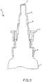
- Distal end 6 can be configured to mate with dispensing mechanism 10, which tapers off, forming a tip 12.
- Dispensing mechanism 10 is configured to dispense a metered volume of liquid medicament when operated. Dispensing may be achieved by pumping or compressing a portion of dispensing mechanism 10.
- Dispensing mechanism 10 can include an interface 14, such as shoulder 14 or other seat or seating mechanism positioned between tip 12 and a flange 16. Shoulder 14 can have a larger diameter than tip 12.
- shoulder 14 may be a shaped step, such as an annular step, that serves as a stop to limit a maximum depth of insertion of tip 12 into an aerosol device.
- Shoulder 14 is inset by a distance that is sufficient so that it not only serves as a stop but also permits tip 12 to seat within an opening an aerosol device in a stable position that is generally vertical to a top surface of an aerosol device.
- the tip 12 is seated within the opening when a surface of the shoulder 14 is flush in contact with a surface of a housing of the aerosol device that defines the opening of the device and the tip extends through the opening. In such a seated position, any liquid medicament within the dispenser will be drawn downward to the tip 12.
- shoulder 14 other seating mechanisms could be used, such as a taper that matches with the taper of an opening in an aerosol device, protruding tabs or wings, detents, and the like.
- the seating mechanism may be keyed such that tip 12 can only be received by the opening in the aerosol device at a certain orientation.
- the shoulder 14 can set the insertion depth of the tip by contacting a surface outside of the opening in the aerosol device such that the tip 12 cannot be inserted further into the device.
- Flange 16 can be used by a patient to apply force to actuate dispensing mechanism 10. Actuation of dispensing mechanism 10 allows tip 12 to be moved relative to proximal end 4, thus compressing dispenser 2. In so doing, each time dispenser 2 is compressed (or "pumped") a metered volume of liquid is ejected from tip 12. For example, Fig. 1 shows dispenser 2 in an uncompressed state. In Fig. 2 , a force is applied to compress dispenser 2 and eject the droplet.
- dispensing mechanism 10 is shown in cross section. For convenience of illustration, the interior of the housing of dispensing mechanism 10 is not shown.
- dispensing mechanism includes a housing cap that fastens dispensing mechanism 10 to a container, such as container 8 described herein. This coupling can be achieved in a variety of ways including, but not limited to, snap fasteners, screw on fasteners, and the like.
- a gasket or O-ring can be included at the junction of container and housing cap to form an airtight seal between the two components.
- the dispensing mechanism 10 can include a fixed portion 34 and a slidable portion 36.
- Fixed portion 34 can be more proximal to the container than slidable portion 36 and is fixed in position relative to the container.
- Slidable portion 36 may be coupled with fixed portion 34.
- the interface between the fixed portion 34 and slidable portion 36 can include a spring that biases the slidable portion 36 in an uncompressed state away from the container.
- a valve within the dispensing mechanism 10 is opened to prime the pump, allowing a volume of the liquid medicament to fill a metering chamber. When filled, this chamber holds a metered dose of the liquid medicament.
- the dispensing mechanism 10 may deliver the metered dose from tip 12 upon compression when primed. Shoulder 14 may be positioned against a surface of a housing of an aerosol device to limit an insertion depth of tip 12.
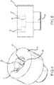
- housing cap 18 may optionally receive an air return filter 22 and can include a notch 24 opposite air return filter 22 for aiding in assembly.
- An aperture or hole 28 may be included on bottom surface 26. Hole 28 helps to extract the last amounts of liquid medicament from container 8 when dispenser 2 is inverted for dispensing the liquid into an aerosol device. In some embodiments, multiple holes may be positioned on opposite sides of the bottom surface, or optionally at positions such that each hole is spaced at the same angle relative to each of the nearest other hole or holes. Additionally bottom surface 26 can be sloped toward the hole 28 to further aid in draining the final remnants of liquid from container 8 as shown in Figure 5 . Hole 28 is sized to be sufficiently large to facilitate drainage of the liquid in the container and into the dispensing mechanism.
- Some embodiments contain only a single hole 28 positioned on bottom surface 26. This arrangement can help keep air out of dispensing mechanism 10 upon tilting dispenser 2 in a way that would otherwise result in a second hole being exposed to air while the first hole 28 was submerged in liquid medicament. By keeping excess air out of dispensing mechanism 10, more reliable dosages can be achieved throughout the life of dispenser 2.
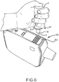
- dispenser 2 is grasped with one hand, such that the four fingers wrap around dispenser 2, mostly about container 8.
- a firm grip is achieved so that dispenser 2 may easily be pumped to eject the liquid.
- the person's thumb may rest on proximal end 4 to apply a further compressive force.
- a cover 302 on inhaler 300 may be slid back and tip 12 placed into opening 304 as shown in Figure 7 . In this inverted position with proximal end 4 above distal end 6, liquid may drain from container 8 into dispensing mechanism 10.
- shoulder 14 may be designed so that tip 12 is sufficiently spaced-apart from mesh 306 so that when the full metered amount of the liquid is dispensed into a reservoir 308, tip 12 does not come into contact with the dispensed liquid. In this way, when dispenser 2 is removed from inhaler 300, it will not remove any of the dispensed liquid. Oftentimes, tip 12 will be spaced apart from mesh 306 by a distance that is in the range from about 5 mm to about 20 mm.
- Tip 12 may also be tapered, such as to match the taper of reservoir 308.
- the taper of reservoir 308 facilitates delivery of all the dispensed liquid onto the rear face of mesh 306, and the tapering of tip 12 prevents tip 12 from coming into contact with the walls of reservoir 308.
- Another exemplary technique for operating dispenser is to use the palm of the hand to exert pressure on the dispenser while docked to the aerosol device.
- the user presses container 8 toward tip 12.
- the user may press container 8 towards tip by wrapping the user's fingers around sides of the dispenser 2 and placing a thumb on proximal end 4 to apply the compressive force.
- a user may position the tip 12 in place within the inhaler 300 and apply a compressive force to the proximal end 4 with the user's palm.
- inhaler 300 is held in place. This causes dispenser 2 to compress.
- the dispensing mechanism permits a metered amount of liquid to be dispensed from tip 12 and into reservoir 308 or onto the vibratable mesh 306.
- Each time container 8 is pressed downward, or pumped, another metered amount of liquid is ejected from tip 12. This maneuver is performed as many times as is needed in order to supply the prescribed dosage into reservoir 308.
- dispenser 2 By holding dispenser 2 in the manner shown, this pumping action may easily occur.
- a nasal spray dispenser which is typically actuated in an upright manner by carefully and simultaneously compressing the distal end with the middle and index finger (with the tip extending between the fingers) to the proximal end of the dispenser container, which is held under equal pressure by the thumb.
- the spray occurs when sufficient pressure is applied equally to both ends.
- dispenser 2 can be easily actuated by applying pressure solely to the proximal end 4 of the dispenser 2 when the tip 12 is engaged with inhaler 300.
- Inhaler 300 and mating features are constructed so that a metered volume of medicament is consistently delivered from dispenser 2 into inhaler 300.
- the user may compress the dispenser 2 with unregulated pressure, provided the force is greater than or equal to that required to compress dispenser 2 throughout its full range. If inhaler 300 is loaded while placed on a table or any other freely supported surface, the apparent force required to compress dispenser 2 into inhaler 300 to the point of actuation is reduced by 50% when compared to the amount of force required to disperse a volume of liquid when holding both inhaler 300 and dispenser 2 (without the aid of a support surface). After dispersing the desired volume of liquid medicament, dispenser 2 may be removed from opening 304 and stored for future use. The cover 302 may be returned to a closed position to seal the opening 304, mesh 306, and reservoir 308.
- the cover 302 may be left open for some period of time to ensure that inner components of the inhaler 300, such as the mesh 306, are exposed to air to sufficiently dry before cover 302 is closed.
- Exemplary unit volumes that may be dispensed with each pump may be in the range from about 20 to about 100 microliters.
- Figures 10 and 11 show close up views of the opening 300, the reservoir 304, and vibratable mesh of inhaler 300.
- the sides of reservoir 304 are tapered such that any dispensed liquid medicament that does not fall onto the vibratable mesh 306 is directed onto the mesh 306.
- the interface 14 limits the insertion depth of tip 12 such that tip 12 does not contact any dispensed liquid medicament.
- the tapered walls of reservoir 304 can be wider than tip 12, such that the sides of tip 12 do not contact the sides of reservoir 304 or any medicament that may be disposed along the reservoir wall.
- inhalers or aerosolizers may be used to aerosolize the dispensed liquid.
- Exemplary aerosol generators that may be used in such inhalers are also described in U.S. Patent Nos. 6629646 ; 6926208 ; 7108197 ; 5938117 ; 6540153 ; 6540154 ; 7040549 ; 6921020 ; 7083112 ; 7628339 ; 5586550 ; 5758637 ; 6085740 ; 6467476 ; 6640804 ; 7174888 ; 6014970 ; 6205999 ; 6755189 ; 6427682 ; 6814071 ; 7066398 ; 6978941 ; 7100600 ; 7032590 ; 7195011 , and in U.S. Patent Publication Nos. 2011/0168172 and 2001/0168170 . These references describe exemplary aerosol generators, ways to manufacture such aerosol generators, and ways to supply liquid for aerosol generator
- the effectiveness of delivering the proper dosage can begin to fall off as the volume of medicament falls below a certain threshold.
- this threshold was approximately 37 actuations for a 3 mL fill volume dispensing a metered volume of 50 ⁇ L. After this point, the user runs the risk of air mixing with the liquid medicament inside a dispensing mechanism, providing an incorrect dosage.
- the containers described herein may optionally include one or more indicator marks that signal to a user when the container needs to be replaced.
- the containers may be constructed of a clear or transparent material so that the level of liquid in the container may be visualized. By comparing the line formed by the level or liquid with the indicator mark, the user can determine whether the level of liquid within the container has fallen below an acceptable level. If so, the user knows that the container should be replaced. The comparison is most easily accomplished by placing the proximal end of the container on a level surface and then peering through the container to ascertain whether the level of liquid has fallen below the indicator mark. While the container may still include some liquid, if the level is below the indicator mark, the level is too low for an acceptable dosing amount, and the container should be replaced.
- some embodiments of the dispenser 2 may optionally include one or more marks along a side of the container 8, which could be in many forms including, but not limited to, a notch or ring that is optionally colored and/or formed by an embossed ridge or depressed notch in the container to provide a visual indication to a user that there is insufficient medicament remaining to ensure a reliable dosage.
- the color of the mark may be selected to help a user distinguish the liquid level from the and mark as the user peers through container 8.
- two spaced apart marks can be used which function as cross-hairs. In other words, if the liquid cannot be visualized through the cross hairs, the user knows that there is no longer a reliable volume of medicament remaining in the container 8.
- container 8 includes a mark 30 that allows a user to identify when the level of liquid medicament falls below a recommended and/or reliable level. If the remaining liquid is below this mark, the user is instructed to discard the container and obtain a fresh container with a full dosage.
- Mark 30 can be a horizontal line around all or part of the sides of the container 8.
- Figure 13-15 shows a top mark 42 separated from a bottom mark 52 by a clear or otherwise transparent horizontal centerline 48 (which is typically the wall of container itself). When the level of the liquid falls below this centerline 48, a user knows that an unreliable volume of the liquid remains. Any size or shape of marks 42 and 52 can be used, and the clear line 48 may be positioned off-center in some embodiments.
- Figure 14 shows a long rectangular top mark 44 separated from a shorter rectangular bottom mark 54 by a clear horizontal line or space 50 positioned at a height to indicate a reliable volume level of the container 8.
- Figure 15 shows an embodiment where the reliable volume is indicated by the liquid being above a bottom edge of a mark 46.
- Mark 46 can be any shape, such as a circle. Other types of marks may be used in conjunction with container 8 to determine a liquid level.
- Figure 16 depicts container 8 having a sloped bottom 32 along with mark 30.
- One reason for provided sloped bottom 32 is that is reduces the interior volume of container 8 at the proximal end. In turn, this allows mark 30 to be positioned vertically higher from the proximal end 4, thereby making mark 30 more easily distinguishable from proximal end 4.
- Other types of sloped bottoms may be used to raise the mark 30 from the proximal end 4.
- Fig. 17 shows container 8 having a concave bottom surface 40 that allows the mark 30 to be raised while still indicating the same volume of liquid.
- a housing cap may also include a dip tube seat, which may aid in orienting the housing cap on the assembly line.
- the dip tube seat may optionally be configured to extend into a container or to be the same height as the housing cap.
- the dip tube seat is formed to be shorter than housing cap.
- the housing cap's bottom surface may be configured to slope towards a base of the dip tube seat.
- One or more holes can be positioned at a base of the dip tube to allow the liquid medicament to access the delivery mechanism.
- a slit that runs the entire longitudinal length of the dip tube seat may be used in place of or in conjunction with the holes for the liquid to pass through. By having the slit run the entire length of the dip tube seat, an efficient draining process can be achieved. Further, this configuration can ease the difficulties associated with manufacturing holes or slits in a dip tube seat.
- the dip tube seat may be configured to have any shape of cross-section, for example, a circular cross-section.
- the dip tube seat may be sealed or blocked at a top end, leaving only the hole or holes as a means for fluid communication between the container and dispensing mechanism.
- the dip tube seat may optionally have the sealing or blocking mechanism set beneath a top edge of the dip tube seat, which can aid in orienting the part on an assembly line during the manufacturing process.
Landscapes
- Health & Medical Sciences (AREA)
- Engineering & Computer Science (AREA)
- Life Sciences & Earth Sciences (AREA)
- Anesthesiology (AREA)
- Bioinformatics & Cheminformatics (AREA)
- Pulmonology (AREA)
- Biomedical Technology (AREA)
- Heart & Thoracic Surgery (AREA)
- Hematology (AREA)
- Animal Behavior & Ethology (AREA)
- General Health & Medical Sciences (AREA)
- Public Health (AREA)
- Veterinary Medicine (AREA)
- Biophysics (AREA)
- Containers And Packaging Bodies Having A Special Means To Remove Contents (AREA)
Claims (10)
- Abgeber (2) zum Zuführen eines dosierten Volumens eines flüssigen Medikaments zu einer Aerosoliervorrichtung, Folgendes umfassend:einen Behälter (8), der ein proximales Ende (4) und ein distales Ende (6) aufweist, wobei der Behälter (8) dazu konfiguriert ist, ein Volumen von flüssigem Medikament zu speichern; undein Abgabemechanismus (10), der mit dem distalen Ende (6) des Behälters (8) gekoppelt ist, wobei der Abgabemechanismus (10) ein distales Ende umfasst, das in einer Spitze endet (12), durch das das flüssige Medikament abgegeben wird, wobei:der Abgabemechanismus (10) eine Gehäusekappe (18) beinhaltet, die den Abgabemechanismus (10) an den Behälter (8) befestigt, wobei die Gehäusekappe (18) eine Bodenfläche (26) und einen Durchlass (28) umfasst und die Bodenfläche (26) der Gehäusekappe (18) zu dem Durchlass (28) hin geneigt ist, um das Abfließen von flüssigem Medikament von dem Behälter (8) in den Abgabemechanismus (10) zu unterstützen,der Abgabemechanismus (10) dazu konfiguriert ist, ein dosiertes Volumen des flüssigen Medikaments von der Spitze (12) jedes Mal abzugeben, wenn der Abgabemechanismus (10) betrieben wird, unddas distale Ende des Abgabemechanismus (10) eine Schnittstelle (14) beinhaltet, die mit einem Gehäuse der Aerosoliervorrichtung wechselwirkt, um eine Einführtiefe der Spitze in eine Öffnung des Gehäuses zu begrenzen;dadurch gekennzeichnet, dassdie Gehäusekappe (18) ferner einen Luftrückführfilter (22) umfasst.
- Abgeber (2) nach Anspruch 1, wobei die Schnittstelle (14) einen Sitz umfasst.
- Abgeber (2) nach Anspruch 1, wobei die Schnittstelle (14) eine Schulter umfasst, wobei die Schulter und die Spitze (12) jeweils einen Durchmesser aufweisen, wobei der Durchmesser der Schulter größer als der Durchmesser der Spitze (12) ist.
- Abgeber (2) nach Anspruch 1, ferner eine Anzeigelinie (30) umfassend, die in der Nähe des proximalen Endes (4) positioniert ist, die einem Benutzer anzeigt, wenn unzureichend Flüssigkeit zur empfohlenen Abgabe vorhanden ist.
- Abgeber (2) nach Anspruch 4, wobei eine Bodenfläche des proximalen Endes (4) geneigt ist, um das Volumen des Behälters (8) an dem proximalen Ende (4) derart zu reduzieren, dass die Anzeigelinie (30) von dem proximalen Ende beabstandet ist.
- Verfahren zum Herstellen eines Abgebers (2) zum Zuführen eines dosierten Volumens eines flüssigen Medikaments zu einer Aerosoliervorrichtung, wobei das Verfahren Folgendes umfasst:Bereitstellen eines Behälters (8), der ein proximales Ende (4) und ein distales Ende (6) aufweist, wobei der Behälter (8) dazu konfiguriert ist, ein Volumen von flüssigem Medikament zu speichern; undBereitstellen eines Abgabemechanismus (10), der betrieben wird, um ein dosiertes Volumen des flüssigen Medikaments von einer Spitze (12) eines distalen Endes des Abgabemechanismus (10) jedes Mal abzugeben, wenn der Abgeber betrieben wird, wobei das distale Ende des Abgabemechanismus eine Schnittstelle (14) umfasst, die mit einem Gehäuse der Aerosoliervorrichtung wechselwirkt, um eine Einführtiefe der Spitzein eine Öffnung des Gehäuses zu begrenzen, wobei der Abgabemechanismus (10) eine Gehäusekappe (18) beinhaltet, die den Abgabemechanismus (10) an den Behälter (8) befestigt, wobei die Gehäusekappe (18)eine Bodenfläche (26) und einen Durchlass (28) umfasst und die Bodenfläche (26) der Gehäusekappe (18) zu dem Durchlass (28) hin geneigt ist, um das Abfließen von flüssigem Medikament von dem Behälter (8) in den Abgabemechanismus (10) zu unterstützen,dadurch gekennzeichnet, dassdie Gehäusekappe (18) ferner einen Luftrückführfilter (22) umfasst.
- Verfahren nach Anspruch 6, wobei die Schnittstelle (14) eine Schulter umfasst, wobei die Schulter und die Spitze (12) jeweils einen Durchmesser aufweisen, wobei der Durchmesser der Schulter größer als der Durchmesser der Spitze (12) ist.
- Verfahren nach Anspruch 6, wobei der Abgeber (2) derart komprimierbar ist, dass der Abgeber (2) ein dosiertes Volumen von flüssigem Medikament bei Anwendung einer Kompressionskraft liefert.
- Verfahren nach Anspruch 6, wobei der Behälter (8) ferner eine Anzeigelinie (30) umfasst, die in der Nähe des proximalen Endes (4) positioniert ist, die einem Benutzer anzeigt, wenn unzureichend Flüssigkeit zur empfohlenen Abgabe vorhanden ist.
- Verfahren nach Anspruch 9, wobei eine Bodenfläche des proximalen Endes (4) geneigt ist, um das Volumen des Behälters (8) an dem proximalen Ende (4) derart zu reduzieren, dass die Anzeigelinie (30) von dem proximalen Ende (4) beabstandet ist.
Applications Claiming Priority (2)
| Application Number | Priority Date | Filing Date | Title |
|---|---|---|---|
| US201361812547P | 2013-04-16 | 2013-04-16 | |
| PCT/US2014/034356 WO2014172455A1 (en) | 2013-04-16 | 2014-04-16 | Liquid dispensing and methods for dispensing liquids |
Publications (3)
| Publication Number | Publication Date |
|---|---|
| EP2986268A1 EP2986268A1 (de) | 2016-02-24 |
| EP2986268A4 EP2986268A4 (de) | 2016-11-23 |
| EP2986268B1 true EP2986268B1 (de) | 2019-05-22 |
Family
ID=55080241
Family Applications (1)
| Application Number | Title | Priority Date | Filing Date |
|---|---|---|---|
| EP14785659.5A Active EP2986268B1 (de) | 2013-04-16 | 2014-04-16 | Flüssigkeitsabgabe |
Country Status (2)
| Country | Link |
|---|---|
| EP (1) | EP2986268B1 (de) |
| ES (1) | ES2734570T3 (de) |
Citations (7)
| Publication number | Priority date | Publication date | Assignee | Title |
|---|---|---|---|---|
| EP0446513A1 (de) * | 1990-03-16 | 1991-09-18 | Kabushiki Kaisha Top | Pumpenanordnung |
| EP0571280A1 (de) * | 1992-05-18 | 1993-11-24 | S O F A B | Spender mit einer Tauchhülse |
| US6250509B1 (en) * | 1998-09-07 | 2001-06-26 | Ing. Erich Pfeiffer Gmbh | Media dispenser |
| US20060255072A1 (en) * | 2005-04-21 | 2006-11-16 | Hagin Susanne E | Metering pump arrangement and method for the production of a filled metering pump arrangement |
| US20070102451A1 (en) * | 2003-10-20 | 2007-05-10 | Samuel Pruvot | Fluid product dispensing device |
| WO2011077123A1 (en) * | 2009-12-23 | 2011-06-30 | Leafgreen Limited | Manual pump type fluid dispenser |
| US20160354795A1 (en) * | 2014-01-30 | 2016-12-08 | Lablabo | Device for packaging and dispensing pasty products |
Family Cites Families (4)
| Publication number | Priority date | Publication date | Assignee | Title |
|---|---|---|---|---|
| US7204248B2 (en) * | 2002-09-27 | 2007-04-17 | Cook Critical Care Incorporated | Fiberoptic nebulizer |
| WO2008097645A1 (en) * | 2007-02-08 | 2008-08-14 | Aerovectrx Corporation | Aerosol delivery systems and methods |
| US20130269684A1 (en) * | 2012-04-16 | 2013-10-17 | Dance Pharmaceuticals, Inc. | Methods and systems for supplying aerosolization devices with liquid medicaments |
| US8950394B2 (en) * | 2010-01-12 | 2015-02-10 | Dance Biopharm Inc. | Preservative-free single dose inhaler systems |
-
2014
- 2014-04-16 ES ES14785659T patent/ES2734570T3/es active Active
- 2014-04-16 EP EP14785659.5A patent/EP2986268B1/de active Active
Patent Citations (7)
| Publication number | Priority date | Publication date | Assignee | Title |
|---|---|---|---|---|
| EP0446513A1 (de) * | 1990-03-16 | 1991-09-18 | Kabushiki Kaisha Top | Pumpenanordnung |
| EP0571280A1 (de) * | 1992-05-18 | 1993-11-24 | S O F A B | Spender mit einer Tauchhülse |
| US6250509B1 (en) * | 1998-09-07 | 2001-06-26 | Ing. Erich Pfeiffer Gmbh | Media dispenser |
| US20070102451A1 (en) * | 2003-10-20 | 2007-05-10 | Samuel Pruvot | Fluid product dispensing device |
| US20060255072A1 (en) * | 2005-04-21 | 2006-11-16 | Hagin Susanne E | Metering pump arrangement and method for the production of a filled metering pump arrangement |
| WO2011077123A1 (en) * | 2009-12-23 | 2011-06-30 | Leafgreen Limited | Manual pump type fluid dispenser |
| US20160354795A1 (en) * | 2014-01-30 | 2016-12-08 | Lablabo | Device for packaging and dispensing pasty products |
Also Published As
| Publication number | Publication date |
|---|---|
| EP2986268A4 (de) | 2016-11-23 |
| EP2986268A1 (de) | 2016-02-24 |
| ES2734570T3 (es) | 2019-12-10 |
Similar Documents
| Publication | Publication Date | Title |
|---|---|---|
| US20200078540A1 (en) | Liquid dispensing and methods for dispensing liquids | |
| US11786676B2 (en) | Methods and systems for supplying aerosolization devices with liquid medicaments | |
| US11285275B2 (en) | Self-puncturing liquid drug cartridges and associated dispenser | |
| US11224706B2 (en) | Dispenser | |
| EP2523716B1 (de) | Konservierungsmittelfreie einzeldosis-inhalatorsysteme | |
| US10682477B2 (en) | Dosing system for an inhalation device | |
| EP4037741B1 (de) | Inhalator | |
| EP2986268A1 (de) | Flüssigkeitsabgabe und verfahren zur abgabe von flüssigkeiten | |
| HK40077495A (en) | Inhaler | |
| HK1237605A1 (en) | Container | |
| HK1225324A1 (en) | Dosing system for an inhalation device | |
| HK1225324B (en) | Dosing system for an inhalation device |
Legal Events
| Date | Code | Title | Description |
|---|---|---|---|
| PUAI | Public reference made under article 153(3) epc to a published international application that has entered the european phase |
Free format text: ORIGINAL CODE: 0009012 |
|
| 17P | Request for examination filed |
Effective date: 20151102 |
|
| AK | Designated contracting states |
Kind code of ref document: A1 Designated state(s): AL AT BE BG CH CY CZ DE DK EE ES FI FR GB GR HR HU IE IS IT LI LT LU LV MC MK MT NL NO PL PT RO RS SE SI SK SM TR |
|
| AX | Request for extension of the european patent |
Extension state: BA ME |
|
| DAX | Request for extension of the european patent (deleted) | ||
| A4 | Supplementary search report drawn up and despatched |
Effective date: 20161026 |
|
| RIC1 | Information provided on ipc code assigned before grant |
Ipc: A61M 15/00 20060101ALI20161020BHEP Ipc: A61J 1/22 20060101ALI20161020BHEP Ipc: B65D 83/42 20060101ALI20161020BHEP Ipc: A61J 1/20 20060101AFI20161020BHEP Ipc: B05B 11/00 20060101ALI20161020BHEP |
|
| STAA | Information on the status of an ep patent application or granted ep patent |
Free format text: STATUS: EXAMINATION IS IN PROGRESS |
|
| 17Q | First examination report despatched |
Effective date: 20170922 |
|
| GRAP | Despatch of communication of intention to grant a patent |
Free format text: ORIGINAL CODE: EPIDOSNIGR1 |
|
| STAA | Information on the status of an ep patent application or granted ep patent |
Free format text: STATUS: GRANT OF PATENT IS INTENDED |
|
| INTG | Intention to grant announced |
Effective date: 20190201 |
|
| GRAS | Grant fee paid |
Free format text: ORIGINAL CODE: EPIDOSNIGR3 |
|
| GRAA | (expected) grant |
Free format text: ORIGINAL CODE: 0009210 |
|
| STAA | Information on the status of an ep patent application or granted ep patent |
Free format text: STATUS: THE PATENT HAS BEEN GRANTED |
|
| AK | Designated contracting states |
Kind code of ref document: B1 Designated state(s): AL AT BE BG CH CY CZ DE DK EE ES FI FR GB GR HR HU IE IS IT LI LT LU LV MC MK MT NL NO PL PT RO RS SE SI SK SM TR |
|
| REG | Reference to a national code |
Ref country code: GB Ref legal event code: FG4D |
|
| REG | Reference to a national code |
Ref country code: CH Ref legal event code: EP |
|
| REG | Reference to a national code |
Ref country code: IE Ref legal event code: FG4D |
|
| REG | Reference to a national code |
Ref country code: DE Ref legal event code: R096 Ref document number: 602014047305 Country of ref document: DE |
|
| REG | Reference to a national code |
Ref country code: AT Ref legal event code: REF Ref document number: 1135212 Country of ref document: AT Kind code of ref document: T Effective date: 20190615 |
|
| REG | Reference to a national code |
Ref country code: NL Ref legal event code: MP Effective date: 20190522 |
|
| REG | Reference to a national code |
Ref country code: LT Ref legal event code: MG4D |
|
| PG25 | Lapsed in a contracting state [announced via postgrant information from national office to epo] |
Ref country code: AL Free format text: LAPSE BECAUSE OF FAILURE TO SUBMIT A TRANSLATION OF THE DESCRIPTION OR TO PAY THE FEE WITHIN THE PRESCRIBED TIME-LIMIT Effective date: 20190522 Ref country code: NL Free format text: LAPSE BECAUSE OF FAILURE TO SUBMIT A TRANSLATION OF THE DESCRIPTION OR TO PAY THE FEE WITHIN THE PRESCRIBED TIME-LIMIT Effective date: 20190522 Ref country code: FI Free format text: LAPSE BECAUSE OF FAILURE TO SUBMIT A TRANSLATION OF THE DESCRIPTION OR TO PAY THE FEE WITHIN THE PRESCRIBED TIME-LIMIT Effective date: 20190522 Ref country code: LT Free format text: LAPSE BECAUSE OF FAILURE TO SUBMIT A TRANSLATION OF THE DESCRIPTION OR TO PAY THE FEE WITHIN THE PRESCRIBED TIME-LIMIT Effective date: 20190522 Ref country code: HR Free format text: LAPSE BECAUSE OF FAILURE TO SUBMIT A TRANSLATION OF THE DESCRIPTION OR TO PAY THE FEE WITHIN THE PRESCRIBED TIME-LIMIT Effective date: 20190522 Ref country code: SE Free format text: LAPSE BECAUSE OF FAILURE TO SUBMIT A TRANSLATION OF THE DESCRIPTION OR TO PAY THE FEE WITHIN THE PRESCRIBED TIME-LIMIT Effective date: 20190522 Ref country code: NO Free format text: LAPSE BECAUSE OF FAILURE TO SUBMIT A TRANSLATION OF THE DESCRIPTION OR TO PAY THE FEE WITHIN THE PRESCRIBED TIME-LIMIT Effective date: 20190822 Ref country code: PT Free format text: LAPSE BECAUSE OF FAILURE TO SUBMIT A TRANSLATION OF THE DESCRIPTION OR TO PAY THE FEE WITHIN THE PRESCRIBED TIME-LIMIT Effective date: 20190922 |
|
| PG25 | Lapsed in a contracting state [announced via postgrant information from national office to epo] |
Ref country code: RS Free format text: LAPSE BECAUSE OF FAILURE TO SUBMIT A TRANSLATION OF THE DESCRIPTION OR TO PAY THE FEE WITHIN THE PRESCRIBED TIME-LIMIT Effective date: 20190522 Ref country code: LV Free format text: LAPSE BECAUSE OF FAILURE TO SUBMIT A TRANSLATION OF THE DESCRIPTION OR TO PAY THE FEE WITHIN THE PRESCRIBED TIME-LIMIT Effective date: 20190522 Ref country code: GR Free format text: LAPSE BECAUSE OF FAILURE TO SUBMIT A TRANSLATION OF THE DESCRIPTION OR TO PAY THE FEE WITHIN THE PRESCRIBED TIME-LIMIT Effective date: 20190823 Ref country code: BG Free format text: LAPSE BECAUSE OF FAILURE TO SUBMIT A TRANSLATION OF THE DESCRIPTION OR TO PAY THE FEE WITHIN THE PRESCRIBED TIME-LIMIT Effective date: 20190822 |
|
| REG | Reference to a national code |
Ref country code: ES Ref legal event code: FG2A Ref document number: 2734570 Country of ref document: ES Kind code of ref document: T3 Effective date: 20191210 |
|
| REG | Reference to a national code |
Ref country code: AT Ref legal event code: MK05 Ref document number: 1135212 Country of ref document: AT Kind code of ref document: T Effective date: 20190522 |
|
| PG25 | Lapsed in a contracting state [announced via postgrant information from national office to epo] |
Ref country code: AT Free format text: LAPSE BECAUSE OF FAILURE TO SUBMIT A TRANSLATION OF THE DESCRIPTION OR TO PAY THE FEE WITHIN THE PRESCRIBED TIME-LIMIT Effective date: 20190522 Ref country code: CZ Free format text: LAPSE BECAUSE OF FAILURE TO SUBMIT A TRANSLATION OF THE DESCRIPTION OR TO PAY THE FEE WITHIN THE PRESCRIBED TIME-LIMIT Effective date: 20190522 Ref country code: SK Free format text: LAPSE BECAUSE OF FAILURE TO SUBMIT A TRANSLATION OF THE DESCRIPTION OR TO PAY THE FEE WITHIN THE PRESCRIBED TIME-LIMIT Effective date: 20190522 Ref country code: RO Free format text: LAPSE BECAUSE OF FAILURE TO SUBMIT A TRANSLATION OF THE DESCRIPTION OR TO PAY THE FEE WITHIN THE PRESCRIBED TIME-LIMIT Effective date: 20190522 Ref country code: EE Free format text: LAPSE BECAUSE OF FAILURE TO SUBMIT A TRANSLATION OF THE DESCRIPTION OR TO PAY THE FEE WITHIN THE PRESCRIBED TIME-LIMIT Effective date: 20190522 Ref country code: DK Free format text: LAPSE BECAUSE OF FAILURE TO SUBMIT A TRANSLATION OF THE DESCRIPTION OR TO PAY THE FEE WITHIN THE PRESCRIBED TIME-LIMIT Effective date: 20190522 |
|
| REG | Reference to a national code |
Ref country code: DE Ref legal event code: R097 Ref document number: 602014047305 Country of ref document: DE |
|
| PG25 | Lapsed in a contracting state [announced via postgrant information from national office to epo] |
Ref country code: SM Free format text: LAPSE BECAUSE OF FAILURE TO SUBMIT A TRANSLATION OF THE DESCRIPTION OR TO PAY THE FEE WITHIN THE PRESCRIBED TIME-LIMIT Effective date: 20190522 |
|
| PLBE | No opposition filed within time limit |
Free format text: ORIGINAL CODE: 0009261 |
|
| STAA | Information on the status of an ep patent application or granted ep patent |
Free format text: STATUS: NO OPPOSITION FILED WITHIN TIME LIMIT |
|
| PG25 | Lapsed in a contracting state [announced via postgrant information from national office to epo] |
Ref country code: TR Free format text: LAPSE BECAUSE OF FAILURE TO SUBMIT A TRANSLATION OF THE DESCRIPTION OR TO PAY THE FEE WITHIN THE PRESCRIBED TIME-LIMIT Effective date: 20190522 |
|
| 26N | No opposition filed |
Effective date: 20200225 |
|
| PG25 | Lapsed in a contracting state [announced via postgrant information from national office to epo] |
Ref country code: PL Free format text: LAPSE BECAUSE OF FAILURE TO SUBMIT A TRANSLATION OF THE DESCRIPTION OR TO PAY THE FEE WITHIN THE PRESCRIBED TIME-LIMIT Effective date: 20190522 |
|
| PG25 | Lapsed in a contracting state [announced via postgrant information from national office to epo] |
Ref country code: SI Free format text: LAPSE BECAUSE OF FAILURE TO SUBMIT A TRANSLATION OF THE DESCRIPTION OR TO PAY THE FEE WITHIN THE PRESCRIBED TIME-LIMIT Effective date: 20190522 |
|
| PG25 | Lapsed in a contracting state [announced via postgrant information from national office to epo] |
Ref country code: MC Free format text: LAPSE BECAUSE OF FAILURE TO SUBMIT A TRANSLATION OF THE DESCRIPTION OR TO PAY THE FEE WITHIN THE PRESCRIBED TIME-LIMIT Effective date: 20190522 |
|
| REG | Reference to a national code |
Ref country code: CH Ref legal event code: PL |
|
| PG25 | Lapsed in a contracting state [announced via postgrant information from national office to epo] |
Ref country code: LI Free format text: LAPSE BECAUSE OF NON-PAYMENT OF DUE FEES Effective date: 20200430 Ref country code: CH Free format text: LAPSE BECAUSE OF NON-PAYMENT OF DUE FEES Effective date: 20200430 Ref country code: LU Free format text: LAPSE BECAUSE OF NON-PAYMENT OF DUE FEES Effective date: 20200416 |
|
| REG | Reference to a national code |
Ref country code: BE Ref legal event code: MM Effective date: 20200430 |
|
| PG25 | Lapsed in a contracting state [announced via postgrant information from national office to epo] |
Ref country code: BE Free format text: LAPSE BECAUSE OF NON-PAYMENT OF DUE FEES Effective date: 20200430 |
|
| PG25 | Lapsed in a contracting state [announced via postgrant information from national office to epo] |
Ref country code: IE Free format text: LAPSE BECAUSE OF NON-PAYMENT OF DUE FEES Effective date: 20200416 |
|
| PG25 | Lapsed in a contracting state [announced via postgrant information from national office to epo] |
Ref country code: MT Free format text: LAPSE BECAUSE OF FAILURE TO SUBMIT A TRANSLATION OF THE DESCRIPTION OR TO PAY THE FEE WITHIN THE PRESCRIBED TIME-LIMIT Effective date: 20190522 Ref country code: CY Free format text: LAPSE BECAUSE OF FAILURE TO SUBMIT A TRANSLATION OF THE DESCRIPTION OR TO PAY THE FEE WITHIN THE PRESCRIBED TIME-LIMIT Effective date: 20190522 |
|
| PG25 | Lapsed in a contracting state [announced via postgrant information from national office to epo] |
Ref country code: MK Free format text: LAPSE BECAUSE OF FAILURE TO SUBMIT A TRANSLATION OF THE DESCRIPTION OR TO PAY THE FEE WITHIN THE PRESCRIBED TIME-LIMIT Effective date: 20190522 Ref country code: IS Free format text: LAPSE BECAUSE OF FAILURE TO SUBMIT A TRANSLATION OF THE DESCRIPTION OR TO PAY THE FEE WITHIN THE PRESCRIBED TIME-LIMIT Effective date: 20190922 |
|
| PGFP | Annual fee paid to national office [announced via postgrant information from national office to epo] |
Ref country code: FR Payment date: 20230328 Year of fee payment: 10 |
|
| PGFP | Annual fee paid to national office [announced via postgrant information from national office to epo] |
Ref country code: GB Payment date: 20230316 Year of fee payment: 10 |
|
| PGFP | Annual fee paid to national office [announced via postgrant information from national office to epo] |
Ref country code: IT Payment date: 20230328 Year of fee payment: 10 Ref country code: ES Payment date: 20230511 Year of fee payment: 10 Ref country code: DE Payment date: 20230314 Year of fee payment: 10 |
|
| REG | Reference to a national code |
Ref country code: DE Ref legal event code: R119 Ref document number: 602014047305 Country of ref document: DE |
|
| GBPC | Gb: european patent ceased through non-payment of renewal fee |
Effective date: 20240416 |
|
| PG25 | Lapsed in a contracting state [announced via postgrant information from national office to epo] |
Ref country code: DE Free format text: LAPSE BECAUSE OF NON-PAYMENT OF DUE FEES Effective date: 20241105 |
|
| PG25 | Lapsed in a contracting state [announced via postgrant information from national office to epo] |
Ref country code: GB Free format text: LAPSE BECAUSE OF NON-PAYMENT OF DUE FEES Effective date: 20240416 |
|
| PG25 | Lapsed in a contracting state [announced via postgrant information from national office to epo] |
Ref country code: FR Free format text: LAPSE BECAUSE OF NON-PAYMENT OF DUE FEES Effective date: 20240430 |
|
| PG25 | Lapsed in a contracting state [announced via postgrant information from national office to epo] |
Ref country code: GB Free format text: LAPSE BECAUSE OF NON-PAYMENT OF DUE FEES Effective date: 20240416 Ref country code: FR Free format text: LAPSE BECAUSE OF NON-PAYMENT OF DUE FEES Effective date: 20240430 Ref country code: DE Free format text: LAPSE BECAUSE OF NON-PAYMENT OF DUE FEES Effective date: 20241105 |
|
| PG25 | Lapsed in a contracting state [announced via postgrant information from national office to epo] |
Ref country code: IT Free format text: LAPSE BECAUSE OF NON-PAYMENT OF DUE FEES Effective date: 20240416 |
|
| REG | Reference to a national code |
Ref country code: ES Ref legal event code: FD2A Effective date: 20250530 |
|
| PG25 | Lapsed in a contracting state [announced via postgrant information from national office to epo] |
Ref country code: ES Free format text: LAPSE BECAUSE OF NON-PAYMENT OF DUE FEES Effective date: 20240417 |