EP2986407B1 - Procede et outil rotatif d'usinage bi-matiere - Google Patents
Procede et outil rotatif d'usinage bi-matiere Download PDFInfo
- Publication number
- EP2986407B1 EP2986407B1 EP14715366.2A EP14715366A EP2986407B1 EP 2986407 B1 EP2986407 B1 EP 2986407B1 EP 14715366 A EP14715366 A EP 14715366A EP 2986407 B1 EP2986407 B1 EP 2986407B1
- Authority
- EP
- European Patent Office
- Prior art keywords
- machining
- tool
- tips
- workpiece
- lining
- Prior art date
- Legal status (The legal status is an assumption and is not a legal conclusion. Google has not performed a legal analysis and makes no representation as to the accuracy of the status listed.)
- Active
Links
Images

Classifications
-
- B—PERFORMING OPERATIONS; TRANSPORTING
- B23—MACHINE TOOLS; METAL-WORKING NOT OTHERWISE PROVIDED FOR
- B23B—TURNING; BORING
- B23B51/00—Tools for drilling machines
- B23B51/10—Bits for countersinking
-
- B—PERFORMING OPERATIONS; TRANSPORTING
- B23—MACHINE TOOLS; METAL-WORKING NOT OTHERWISE PROVIDED FOR
- B23B—TURNING; BORING
- B23B29/00—Holders for non-rotary cutting tools; Boring bars or boring heads; Accessories for tool holders
- B23B29/03—Boring heads
- B23B29/034—Boring heads with tools moving radially, e.g. for making chamfers or undercuttings
- B23B29/03403—Boring heads with tools moving radially, e.g. for making chamfers or undercuttings radially adjustable before starting manufacturing
-
- B—PERFORMING OPERATIONS; TRANSPORTING
- B23—MACHINE TOOLS; METAL-WORKING NOT OTHERWISE PROVIDED FOR
- B23B—TURNING; BORING
- B23B29/00—Holders for non-rotary cutting tools; Boring bars or boring heads; Accessories for tool holders
- B23B29/03—Boring heads
- B23B29/034—Boring heads with tools moving radially, e.g. for making chamfers or undercuttings
- B23B29/03403—Boring heads with tools moving radially, e.g. for making chamfers or undercuttings radially adjustable before starting manufacturing
- B23B29/03417—Boring heads with tools moving radially, e.g. for making chamfers or undercuttings radially adjustable before starting manufacturing by means of inclined planes
-
- B—PERFORMING OPERATIONS; TRANSPORTING
- B23—MACHINE TOOLS; METAL-WORKING NOT OTHERWISE PROVIDED FOR
- B23B—TURNING; BORING
- B23B41/00—Boring or drilling machines or devices specially adapted for particular work; Accessories specially adapted therefor
- B23B41/12—Boring or drilling machines or devices specially adapted for particular work; Accessories specially adapted therefor for forming working surfaces of cylinders, of bearings, e.g. in heads of driving rods, or of other engine parts
-
- B—PERFORMING OPERATIONS; TRANSPORTING
- B23—MACHINE TOOLS; METAL-WORKING NOT OTHERWISE PROVIDED FOR
- B23B—TURNING; BORING
- B23B2215/00—Details of workpieces
- B23B2215/24—Components of internal combustion engines
-
- B—PERFORMING OPERATIONS; TRANSPORTING
- B23—MACHINE TOOLS; METAL-WORKING NOT OTHERWISE PROVIDED FOR
- B23B—TURNING; BORING
- B23B2215/00—Details of workpieces
- B23B2215/24—Components of internal combustion engines
- B23B2215/242—Cylinder liners
-
- B—PERFORMING OPERATIONS; TRANSPORTING
- B23—MACHINE TOOLS; METAL-WORKING NOT OTHERWISE PROVIDED FOR
- B23B—TURNING; BORING
- B23B2228/00—Properties of materials of tools or workpieces, materials of tools or workpieces applied in a specific manner
- B23B2228/36—Multi-layered
-
- B—PERFORMING OPERATIONS; TRANSPORTING
- B23—MACHINE TOOLS; METAL-WORKING NOT OTHERWISE PROVIDED FOR
- B23B—TURNING; BORING
- B23B2251/00—Details of tools for drilling machines
- B23B2251/50—Drilling tools comprising cutting inserts
Definitions
- the present invention relates to the machining of mechanical members, in particular of the upper face of the cylinder blocks of internal combustion engines.
- This invention also relates to a rotary tool according to the preamble of claim 6 bi-material machining, especially designed for the implementation of such a method.
- FR 2 874 027 A shows an example of such a method and such a tool.
- cylinder blocks comprising a body made of soft metal, in particular aluminum-based, in which bores, or cylinders, provided with hard metal jackets, are formed. based on cast iron.
- These bi-material cylinder blocks are cast in aluminum, with preforms for cast iron cylinder liners. Finally, the upper face of the aluminum block is flush with an end face of each cast iron jacket.
- the machining of bi-material metal parts is a delicate operation, especially when the two materials concerned have different hardnesses and mechanical characteristics. This operation requires specific tools, the life of which is generally limited by the differential wear of the cutting parts.
- the problems associated with two-material machining arise on all parts composed partly of a ferrous material and partly of a non-ferrous material (for example cast iron and aluminum or cast iron and steel). It is found in particular on the upper face of aluminum engine cylinder blocks, whose cylinders are internally lined with cast iron shirts.
- the present invention aims to increase the life of milling tools. In the particular case of engine cylinder blocks combustion, it reduces the risk of scratches on the combustion side, improving the reliability of surfacing operations.
- the tool has for this purpose a series of countersinks, suitable for making a flat bottom drilling in the material of the part and that of the coating, and a series of plates axially offset on the tool body compared to the first .
- the second plates penetrate more into the material of the coating than the first, to realize at the upper end thereof, chamfers oriented towards the inside of the orifice.
- a bi-material rotary machining tool in accordance with the invention capable of machining a bi-material mechanical part face by dipping holes aligned on the axis of cylindrical orifices, which are open on the face of the piece, and lined internally with a material of hardness greater than that of the piece.
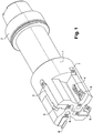
- the tool is composed of a tool body 1, provided with a shoulder 2 attached to a rotary drive machine (not shown), and four cartridge holders 3 with their clamping means 4. cartridges have adjustment means in diameter 6 and adjustment means in thickness 7.
- the plates are of two types: triangular plates 8, and square plates 9.
- the triangular plates 8 are countersinks capable of making a hole in the material of the cylinder block, the piece 11, and that of the jacket 13.
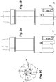
- the tool of figure 1 carries four plates, including two diametrically opposed counterbore plates 8 and two diametrically opposed chamfer plates 9, which are found on the Figures 2A, 2B , and on the cut of the Figure 2C .
- the Figures 2B and 2C show the axial offset (e) of the chamfer plates 9 with respect to the counterbore plates 8.
- the mechanical part is an aluminum combustion engine cylinder block, the cylinders of which are lined internally with jackets. cast.
- the three FIGS. 3A, 3B, 3C are partial vertical sections of a cylinder block 11, made in the diametral plane of a cylinder 12. figure 3A , the upper surface 11a of the block is essentially flat (with manufacturing defects near).
- the figure 3B illustrates the combined operation of counterbore and "chamfering", which is performed in the material of the cylinder block 11 and that of the sleeve 13.
- the tool performs the dual counterbore -material releasing at the upper part of the cylinder 12, on the one hand a bore blank in the mass of the part and that of the coating, and on the other hand the chamfer 16, the nominal height is determined by the axial offset platelets 8, 9, and corresponds therewith.
- the countersinks 8 leave a machining allowance in the requested tolerance.
- the chamfer plates 9, which penetrate further into the material perform the chamfer 16.
- the result of the operation is a flat-bottomed hole 14a and a straight edge 14b in the materials of the block 11 and the sleeve 13, with the chamfer 16 in the only material of the shirt 13 (cf. Fig. 3C ).
- the proposed bi-material machining method makes it possible to perform, in a single tool pass, a two-material countersink of the cylinder block, a machining of the chamfers.
- a planing milling operation can then be performed during a second tool pass, with a pass depth of 0.20 to 0.30mm.
- the proposed method allows to decrease the depth of pass in the cast iron part. This decrease has the effect of increasing the life of the tool and ensuring a better surface quality. She finds a particular interest in the machining of upper surface of cylinder block.
- This method can be applied in general to all bi-material machining requiring precise surfacing. In the automotive field, these are parts such as cylinder block (or crankcase), cylinder head, gearbox housing, pump, various spare parts, etc.
- This invention can also find relevant applications in other fields, such as aeronautics, for the machining of bi-material parts, for example magnesium and aluminum or other.
- bi-material machining indeed allows a good diffusion of heat, thus avoiding the risk of breakage and cracking, on parts subjected to high temperatures.
Landscapes
- Engineering & Computer Science (AREA)
- Mechanical Engineering (AREA)
- Cylinder Crankcases Of Internal Combustion Engines (AREA)
- Drilling And Boring (AREA)
- Cutting Tools, Boring Holders, And Turrets (AREA)
Description
- La présente invention se rapporte à l'usinage des organes mécaniques, notamment de la face supérieure des blocs-cylindres de moteurs à combustion interne.
- Plus précisément, elle a pour objet un procédé selon le préambule de la revendication 1 d'usinage d'une pièce mécanique bi-matière présentant des orifices cylindriques revêtus intérieurement d'un matériau de dureté supérieure à la sienne, qui affleure sur sa face extérieure, avec un outil de fraisage rotatif.
- Cette invention a également pour objet un outil rotatif selon le préambule de la revendication 6 d'usinage bi-matière, spécialement conçu pour la mise en oeuvre d'un tel procédé.
-
FR 2 874 027 A - Elle trouve une application privilégiée, mais non limitative, dans l'usinage de bloc-cylindres de moteurs en aluminium avec des chemises en fonte.
- Les moteurs à combustion interne pour véhicule automobile sont équipés dans certains cas, de blocs-cylindres comprenant un corps en métal tendre, notamment à base d'aluminium, dans lequel sont ménagés des alésages, ou cylindres, munis de chemises en métal dur, notamment à base de fonte. Ces blocs-cylindres bi-matière sont coulés en aluminium, avec des préformes pour les chemises de cylindre en fonte. Au final, la face supérieure du bloc en aluminium affleure avec une face d'extrémité de chaque chemise en fonte.
- Le surfaçage de la face supérieure des usinages bi-matière, peut être réalisé avec de simples fraises à surfacer. Cependant, les outils habituels ne garantissent pas le niveau de qualité souhaité pour les faces de combustion, car le risque de rayures sur celle-ci n'est pas exclu.
- L'usinage de pièces métalliques bi-matière est une opération délicate, notamment lorsque les deux matières concernées présentent des duretés et des caractéristiques mécaniques différentes. Cette opération nécessite des outillages spécifiques, dont la durée de vie est généralement limitée par l'usure différentielle des pièces coupantes. Les problèmes liés à l'usinage bi-matière se posent sur toutes les pièces composées pour partie d'un matériau ferreux et pour partie d'un matériau non ferreux (par exemple fonte et aluminium ou fonte et acier). On le rencontre en particulier sur la face supérieure des blocs-cylindres de moteurs en aluminium, dont les cylindres sont revêtus intérieurement de chemises en fonte.
- La présente invention vise à augmenter la durée de vie des outils de fraisage. Dans le cas particulier des blocs-cylindres de moteur à combustion, elle permet de diminuer les risques de rayures sur la face combustion, en améliorant la fiabilité des opérations de surfaçage.
- Dans ce but, elle prévoit les caractéristiques du procédé de la revendication 1 ou de l'outil rotatif de la revendication 6.
- L'outil présente à cet effet une série de plaquettes de lamage, aptes à réaliser un perçage à fond plat dans la matière de la pièce et celle du revêtement, et une série de plaquettes décalées axialement sur le corps d'outil par rapport aux premières. Les deuxièmes plaquettes pénètrent davantage dans la matière du revêtement que les premières, pour réaliser à l'extrémité supérieure de celui-ci, des chanfreins orientés vers l'intérieur de l'orifice.
- La présente invention sera mieux comprise à la lecture de la description suivante d'un mode de réalisation non limitatif de celle-ci, en se reportant aux dessins annexés, sur lesquels :
- la
figure 1 est une vue d'ensemble de l'outil proposé, - les
figures 2A, 2B, 2C montrent le décalage des plaquettes, et - les
figures 3A, 3B, et 3C illustrent le procédé. - Sur la
figure 1 , on a représenté un outil d'usinage rotatif bi-matière conforme à l'invention, apte à usiner une face de pièce mécanique bi-matière en réalisant en plongée des perçages alignés sur l'axe d'orifices cylindriques, qui sont ouverts sur la face de la pièce, et revêtus intérieurement d'une matière de dureté supérieure à celle de la pièce. L'outil est composé d'un corps d'outil 1, muni d'un épaulement 2 de rattachement à une machine d'entraînement rotative (non représentée), et de quatre cartouches porte-plaquettes 3 avec leurs moyens de serrage 4. Les cartouches disposent de moyens de réglage en diamètre 6 et de moyens de réglage en épaisseur 7. Les plaquettes sont de deux type : des plaquettes triangulaires 8, et des plaquettes carrées 9. Les plaquettes triangulaires 8 sont des plaquettes de lamage aptes à réaliser un perçage à fond plat dans la matière du bloc-cylindres, la pièce 11, et celle de la chemise 13. La deuxième série de plaquettes 9, décalées axialement sur le corps d'outil par rapport aux premières, pénètre davantage dans la matière du revêtement pour réaliser un chanfrein à l'extrémité supérieure de celui-ci. Le chanfrein 16, orienté vers l'intérieur du cylindre, est visible sur lesfigures 3B et 3C . - L'outil de la
figure 1 porte quatre plaquettes, dont deux plaquettes de lamage 8 diamétralement opposées et deux plaquettes de chanfrein 9 diamétralement opposées, qu'on retrouve sur lesfigures 2A, 2B , et sur la coupe de lafigure 2C . Lesfigures 2B et 2C mettent en évidence le décalage axial (e) des plaquettes de chanfrein 9 par rapport aux plaquettes de lamage 8. Dans l'exemple décrit, la pièce mécanique est un bloc cylindres de moteur à combustion en aluminium, dont les cylindres sont revêtus intérieurement de chemises en fonte. Les troisfigures 3A, 3B, 3C sont des coupes verticales partielles d'un bloc cylindre 11, effectuées dans le plan diamétral d'un cylindre 12. Sur lafigure 3A , la surface supérieure 11a du bloc est essentiellement plane (aux défauts de fabrication près). L'extrémité supérieure de la chemise 13, par exemple en fonte, affleure la face 11a. Lafigure 3B illustre l'opération combinée de lamage et de « chanfreinage », qui est réalisée dans la matière du bloc-cylindres 11 et celle de la chemise 13. En une seule plongée, calée axialement sur le cylindre 12, l'outil réalise le lamage bi-matière dégageant à la partie supérieure du cylindre 12, d'une part une ébauche d'alésage dans la masse de la pièce et celle du revêtement, et d'autre part le chanfrein 16, dont la hauteur nominale est déterminée par le décalage axial des plaquettes 8, 9, et correspond à celui-ci. - Lors de la « plongée », les plaquettes de lamage 8 laissent une surépaisseur d'usinage dans la tolérance demandée. Simultanément, les plaquettes de chanfrein 9, qui pénètrent davantage dans la matière, réalisent le chanfrein 16. Le résultat de l'opération est un perçage à fond plat 14a et bord droit 14b dans les matières du bloc 11 et de la chemise 13, avec le chanfrein 16 dans la seule matière de la chemise 13 (cf.
figure. 3C ). - En conclusion, le procédé d'usinage bi-matière proposé permet d'effectuer en un seul passage d'outil un lamage bi-matière du bloc-cylindres un usinage des chanfreins. Une opération de fraisage surfaçage peut ensuite être réalisée au cours d'un deuxième passage outil, avec une profondeur de passe de 0,20 à 0.30mm. La méthode proposée permet de diminuer la profondeur de passe dans la partie fonte. Cette diminution a pour effet d'augmenter la durée de vie de l'outil et d'assurer une meilleure qualité de surface. Elle trouve un intérêt particulier dans l'usinage de surface supérieure de bloc cylindres. Cette méthode peut s'appliquer de manière générale à l'ensemble des usinages bi-matière nécessitant un surfaçage précis. Dans le domaine automobile, il s'agit de pièces telles que bloc-cylindres (ou carter-cylindres), culasse, carter de boîte de vitesses, pompe, diverses pièces détachées, etc. Cette invention peut trouver également des applications pertinentes dans d'autres domaines, tels que l'aéronautique, pour l'usinage de pièces bi-matière, par exemple en magnésium et en aluminium ou autres. Dans la plupart des cas, l'usinage bi-matière permet en effet une bonne diffusion de la chaleur, évitant ainsi les risques de casse et de craquelures, sur des pièces soumises à des températures élevées.
Claims (8)
- Procédé d'usinage d'une pièce mécanique bi-matière (11) présentant des orifices cylindriques (12) revêtus intérieurement d'un matériau de dureté supérieure à la sienne affleurant sur sa face extérieure, avec un outil de fraisage rotatif, caractérisé en ce que l'outil réalise en un seul passage en plongée axiale dans l'orifice cylindrique (12), d'une part un lamage bi-matière dégageant à la partie supérieure de l'orifice (12) une ébauche d'alésage dans la masse de la pièce et celle du revêtement, et d'autre part un chanfrein (16) sur l'extrémité supérieure du revêtement (13), qui est orienté vers le centre de l'orifice cylindrique (12).
- Procédé d'usinage bi-matière selon la revendication 1, caractérisé en ce que les opérations de lamage et de chanfreinage sont réalisées respectivement par des plaquettes lamage (8) et des plaquettes de chanfrein (9) décalées axialement par rapport aux premières, de manière à pénétrer davantage dans l'épaisseur de la matière que celles-ci.
- Procédé d'usinage bi-matière selon la revendication 2, caractérisé en ce que le résultat du passage de l'outil est un perçage à fond plat (14a) et à bord droit (14b) dans les matières de la pièce (11) et du revêtement (13) avec un chanfrein de transition (16) orienté obliquement vers le centre de l'orifice cylindrique (12), dans la matière du revêtement (13).
- Procédé d'usinage selon la revendication 1, 2 ou 3, caractérisé en ce que la hauteur nominale du chanfrein (16) correspond au décalage axial des plaquettes (8, 9) sur l'outil.
- Procédé d'usinage selon l'une des revendications précédentes, caractérisé en ce que la pièce mécanique (11) est un bloc-cylindres de moteur à combustion en aluminium, dont les cylindres (12) sont revêtus intérieurement de chemises en fonte (13).
- Outil rotatif d'usinage d'une face de pièce mécanique bi-matière (11), apte à réaliser en plongée des perçages alignés sur l'axe d'orifices cylindriques (12) qui sont ouverts sur une face (11a) de la pièce et revêtus intérieurement d'une matière (13) de dureté supérieure à celle de la pièce, caractérisé en ce qu'il présente deux plaquettes de lamage (8) triangulaires diamétralement opposées, aptes à réaliser un perçage à fond plat dans la matière de la pièce et celle du revêtement, et deux plaquettes de chanfrein (9) de forme carrée, diamétralement opposées, décalées axialement sur le corps d'outil par rapport aux plaquettes de lamage, de manière à pénétrer davantage dans la matière du revêtement (13) pour réaliser à l'extrémité supérieure de celui-ci, des chanfreins (16) orientés vers l'intérieur de l'orifice (12).
- Outil rotatif d'usinage selon la revendication 6, caractérisé en ce que la hauteur nominale du chanfrein (16) est déterminée par le décalage axial (e) des plaquettes (8, 9) .
- Outil rotatif d'usinage selon la revendications 6 ou 7, caractérisé en ce que ses plaquettes (8, 9) sont décalées axialement de manière d'une part à réaliser en un seul passage, l'usinage de surface d'un bloc-cylindres (11) de moteur à combustion en aluminium dont les cylindres sont revêtus intérieurement de chemises en fonte (13) et d'autre part à former un chanfrein (16) orienté obliquement vers l'intérieur du cylindre à l'extrémité supérieure des chemises (13).
Applications Claiming Priority (2)
| Application Number | Priority Date | Filing Date | Title |
|---|---|---|---|
| FR1353383A FR3004367B1 (fr) | 2013-04-15 | 2013-04-15 | Procede et outil rotatif d'usinage bi-matiere |
| PCT/FR2014/050573 WO2014170564A1 (fr) | 2013-04-15 | 2014-03-13 | Procede et outil rotatif d'usinage bi-matiere |
Publications (2)
| Publication Number | Publication Date |
|---|---|
| EP2986407A1 EP2986407A1 (fr) | 2016-02-24 |
| EP2986407B1 true EP2986407B1 (fr) | 2019-08-21 |
Family
ID=48613986
Family Applications (1)
| Application Number | Title | Priority Date | Filing Date |
|---|---|---|---|
| EP14715366.2A Active EP2986407B1 (fr) | 2013-04-15 | 2014-03-13 | Procede et outil rotatif d'usinage bi-matiere |
Country Status (5)
| Country | Link |
|---|---|
| EP (1) | EP2986407B1 (fr) |
| JP (1) | JP6484606B2 (fr) |
| CN (1) | CN105188997B (fr) |
| FR (1) | FR3004367B1 (fr) |
| WO (1) | WO2014170564A1 (fr) |
Families Citing this family (6)
| Publication number | Priority date | Publication date | Assignee | Title |
|---|---|---|---|---|
| JP6478380B2 (ja) * | 2014-09-01 | 2019-03-06 | 株式会社 上田製作所 | 座ぐりカッター |
| US20190084063A1 (en) * | 2017-09-15 | 2019-03-21 | Korloy Inc | Tool for processing engine block and method of processing engine block |
| DE102019200829B4 (de) * | 2019-01-24 | 2025-02-13 | Audi Ag | Rotations-Werkzeug zur Erzeugung eines Honfreigangs |
| CN110253039A (zh) * | 2019-06-13 | 2019-09-20 | 广合科技(广州)有限公司 | 一种锥形沉头孔的加工方法 |
| KR102209601B1 (ko) * | 2020-01-29 | 2021-01-28 | 손용학 | 평면 및 모따기 연속가공용 밀링커터 |
| EP4035808A1 (fr) | 2021-02-01 | 2022-08-03 | KOMET Deutschland GmbH | Élément de coupe et outil d'usinage par enlèvement de copeaux |
Family Cites Families (12)
| Publication number | Priority date | Publication date | Assignee | Title |
|---|---|---|---|---|
| US3018675A (en) * | 1959-11-23 | 1962-01-30 | Wesson Corp | Boring bar |
| JPH01108345U (fr) * | 1988-01-11 | 1989-07-21 | ||
| DE9207000U1 (de) * | 1992-05-23 | 1993-06-24 | Heule, Heinrich, Au | Entgratwerkzeug mit zusätzlichem Schneidwerkzeug |
| DE29622294U1 (de) * | 1996-12-21 | 1997-02-27 | Ciupek, Gabriele, 50389 Wesseling | Werkzeug zum Ausbohren von in Rohrbündelplatten eingesetzten und verschweißten Rohren eines Rohrbündelwärmetauschers |
| CN2283537Y (zh) * | 1997-03-31 | 1998-06-10 | 河南第一工具厂 | 摩托车气缸用硬质合金复合锪刀 |
| US6033161A (en) * | 1998-08-27 | 2000-03-07 | Scheufler, Jr.; Richard A. | Revolving pilot tool |
| JP2002052414A (ja) * | 2000-08-08 | 2002-02-19 | Nissan Motor Co Ltd | スローアウェイチップおよびスローアウェイ式カッタツール |
| DE102004038180A1 (de) * | 2004-08-06 | 2006-03-16 | Daimlerchrysler Ag | Verfahren zur Herstellung einer thermisch beschichteten Zylinderlauffläche mit einer Endfase |
| EP2254715B1 (fr) * | 2008-03-18 | 2013-05-15 | MAPAL Fabrik für Präzisionswerkzeuge Dr. Kress KG | Outil |
| US9028178B2 (en) * | 2009-06-30 | 2015-05-12 | Sandvik, Inc. | Multi-effective material removal tool |
| CN201543841U (zh) * | 2009-09-22 | 2010-08-11 | 广西玉柴机器股份有限公司 | 一种加工气缸体止口的可调整精镗刀 |
| JP5532960B2 (ja) * | 2010-01-26 | 2014-06-25 | トヨタ自動車株式会社 | 溶射被膜の加工方法 |
-
2013
- 2013-04-15 FR FR1353383A patent/FR3004367B1/fr not_active Expired - Fee Related
-
2014
- 2014-03-13 JP JP2016507023A patent/JP6484606B2/ja active Active
- 2014-03-13 WO PCT/FR2014/050573 patent/WO2014170564A1/fr not_active Ceased
- 2014-03-13 EP EP14715366.2A patent/EP2986407B1/fr active Active
- 2014-03-13 CN CN201480026151.2A patent/CN105188997B/zh active Active
Non-Patent Citations (1)
| Title |
|---|
| None * |
Also Published As
| Publication number | Publication date |
|---|---|
| WO2014170564A1 (fr) | 2014-10-23 |
| FR3004367A1 (fr) | 2014-10-17 |
| FR3004367B1 (fr) | 2015-08-21 |
| EP2986407A1 (fr) | 2016-02-24 |
| CN105188997B (zh) | 2018-05-11 |
| JP6484606B2 (ja) | 2019-03-13 |
| CN105188997A (zh) | 2015-12-23 |
| JP2016516597A (ja) | 2016-06-09 |
Similar Documents
| Publication | Publication Date | Title |
|---|---|---|
| EP2986407B1 (fr) | Procede et outil rotatif d'usinage bi-matiere | |
| CA2137437C (fr) | Foret de percage a tete hemispherique a coupe evolutive | |
| CA2481804C (fr) | Foret ceramique pour percage grande vitesse | |
| CN101389432B (zh) | 非轴对称刃钻头 | |
| CN104302430B (zh) | 由具有最终加工余量的现有孔切削制造精确配合的柱状孔的方法和刀具 | |
| CA2637652A1 (fr) | Foret ceramique pour percage grande vitesse de materiaux composites | |
| JP6215156B2 (ja) | 中空エンジンバルブ及びその製造方法 | |
| FR2913619A3 (fr) | Outil multitache de percage, taraudage, chanfreinage | |
| FR2786232A1 (fr) | Bielle divisee, en particulier pour moteur a combustion interne, et procede pour sa fabrication | |
| EP3003619B1 (fr) | Outil coupant rotatif presentant une arete de coupe en plusieurs materiaux. | |
| US20130031782A1 (en) | Method for producing a piston for an internal combustion engine | |
| EP3104997B1 (fr) | Outil tournant d'alésage à plaquettes amovibles de coupe et procédé d'usinage d'un alésage de moteur à combustion | |
| CN104439991B (zh) | 一种重型汽车轮间拨叉差速的加工方法 | |
| CN211539622U (zh) | 用于加工汽车嵌体的pcd成型铣刀 | |
| JP2010125532A (ja) | リーマ | |
| FR2521468A1 (fr) | Foret | |
| CN111468768A (zh) | 用于产生珩磨通道的旋转刀具 | |
| US10315254B2 (en) | Method of machining dissimilar materials | |
| EP0029764A1 (fr) | Plaquette de coupe adaptée à l'usinage des matériaux réfractaires | |
| JP5667221B2 (ja) | 複合切削刃具及びワークの切削加工方法 | |
| FR3089439A1 (fr) | Outil de tournage, procede de fabrication de piston et piston | |
| FR3054969A1 (fr) | Outil de poinconnage et outil d’emboutissage pour une ebauche de piece pour un vehicule, notamment automobile | |
| FR2946907A1 (fr) | Procede de fabrication d'une culasse munie d'une paroi de guidage d'ecoulement au niveau d'un siege de soupape | |
| FR3002169A3 (fr) | Plaquette amovible de coupe, outil tournant d'alesage a plaquettes amovibles de coupe et procede d'usinage d'un alesage de moteur a combustion | |
| JP2012106301A (ja) | リーマおよびそれを用いた穴の形成方法 |
Legal Events
| Date | Code | Title | Description |
|---|---|---|---|
| PUAI | Public reference made under article 153(3) epc to a published international application that has entered the european phase |
Free format text: ORIGINAL CODE: 0009012 |
|
| 17P | Request for examination filed |
Effective date: 20151001 |
|
| AK | Designated contracting states |
Kind code of ref document: A1 Designated state(s): AL AT BE BG CH CY CZ DE DK EE ES FI FR GB GR HR HU IE IS IT LI LT LU LV MC MK MT NL NO PL PT RO RS SE SI SK SM TR |
|
| AX | Request for extension of the european patent |
Extension state: BA ME |
|
| DAX | Request for extension of the european patent (deleted) | ||
| GRAP | Despatch of communication of intention to grant a patent |
Free format text: ORIGINAL CODE: EPIDOSNIGR1 |
|
| STAA | Information on the status of an ep patent application or granted ep patent |
Free format text: STATUS: GRANT OF PATENT IS INTENDED |
|
| RIC1 | Information provided on ipc code assigned before grant |
Ipc: B23B 51/10 20060101ALI20190306BHEP Ipc: B23B 29/034 20060101ALI20190306BHEP Ipc: B23B 41/12 20060101AFI20190306BHEP |
|
| INTG | Intention to grant announced |
Effective date: 20190408 |
|
| GRAS | Grant fee paid |
Free format text: ORIGINAL CODE: EPIDOSNIGR3 |
|
| GRAA | (expected) grant |
Free format text: ORIGINAL CODE: 0009210 |
|
| STAA | Information on the status of an ep patent application or granted ep patent |
Free format text: STATUS: THE PATENT HAS BEEN GRANTED |
|
| AK | Designated contracting states |
Kind code of ref document: B1 Designated state(s): AL AT BE BG CH CY CZ DE DK EE ES FI FR GB GR HR HU IE IS IT LI LT LU LV MC MK MT NL NO PL PT RO RS SE SI SK SM TR |
|
| REG | Reference to a national code |
Ref country code: GB Ref legal event code: FG4D Free format text: NOT ENGLISH |
|
| REG | Reference to a national code |
Ref country code: CH Ref legal event code: EP |
|
| REG | Reference to a national code |
Ref country code: DE Ref legal event code: R096 Ref document number: 602014052100 Country of ref document: DE |
|
| REG | Reference to a national code |
Ref country code: AT Ref legal event code: REF Ref document number: 1169135 Country of ref document: AT Kind code of ref document: T Effective date: 20190915 |
|
| REG | Reference to a national code |
Ref country code: IE Ref legal event code: FG4D Free format text: LANGUAGE OF EP DOCUMENT: FRENCH |
|
| REG | Reference to a national code |
Ref country code: LT Ref legal event code: MG4D |
|
| REG | Reference to a national code |
Ref country code: NL Ref legal event code: MP Effective date: 20190821 |
|
| PG25 | Lapsed in a contracting state [announced via postgrant information from national office to epo] |
Ref country code: PT Free format text: LAPSE BECAUSE OF FAILURE TO SUBMIT A TRANSLATION OF THE DESCRIPTION OR TO PAY THE FEE WITHIN THE PRESCRIBED TIME-LIMIT Effective date: 20191223 Ref country code: NO Free format text: LAPSE BECAUSE OF FAILURE TO SUBMIT A TRANSLATION OF THE DESCRIPTION OR TO PAY THE FEE WITHIN THE PRESCRIBED TIME-LIMIT Effective date: 20191121 Ref country code: SE Free format text: LAPSE BECAUSE OF FAILURE TO SUBMIT A TRANSLATION OF THE DESCRIPTION OR TO PAY THE FEE WITHIN THE PRESCRIBED TIME-LIMIT Effective date: 20190821 Ref country code: FI Free format text: LAPSE BECAUSE OF FAILURE TO SUBMIT A TRANSLATION OF THE DESCRIPTION OR TO PAY THE FEE WITHIN THE PRESCRIBED TIME-LIMIT Effective date: 20190821 Ref country code: LT Free format text: LAPSE BECAUSE OF FAILURE TO SUBMIT A TRANSLATION OF THE DESCRIPTION OR TO PAY THE FEE WITHIN THE PRESCRIBED TIME-LIMIT Effective date: 20190821 Ref country code: HR Free format text: LAPSE BECAUSE OF FAILURE TO SUBMIT A TRANSLATION OF THE DESCRIPTION OR TO PAY THE FEE WITHIN THE PRESCRIBED TIME-LIMIT Effective date: 20190821 Ref country code: NL Free format text: LAPSE BECAUSE OF FAILURE TO SUBMIT A TRANSLATION OF THE DESCRIPTION OR TO PAY THE FEE WITHIN THE PRESCRIBED TIME-LIMIT Effective date: 20190821 Ref country code: BG Free format text: LAPSE BECAUSE OF FAILURE TO SUBMIT A TRANSLATION OF THE DESCRIPTION OR TO PAY THE FEE WITHIN THE PRESCRIBED TIME-LIMIT Effective date: 20191121 |
|
| PG25 | Lapsed in a contracting state [announced via postgrant information from national office to epo] |
Ref country code: ES Free format text: LAPSE BECAUSE OF FAILURE TO SUBMIT A TRANSLATION OF THE DESCRIPTION OR TO PAY THE FEE WITHIN THE PRESCRIBED TIME-LIMIT Effective date: 20190821 Ref country code: AL Free format text: LAPSE BECAUSE OF FAILURE TO SUBMIT A TRANSLATION OF THE DESCRIPTION OR TO PAY THE FEE WITHIN THE PRESCRIBED TIME-LIMIT Effective date: 20190821 Ref country code: LV Free format text: LAPSE BECAUSE OF FAILURE TO SUBMIT A TRANSLATION OF THE DESCRIPTION OR TO PAY THE FEE WITHIN THE PRESCRIBED TIME-LIMIT Effective date: 20190821 Ref country code: RS Free format text: LAPSE BECAUSE OF FAILURE TO SUBMIT A TRANSLATION OF THE DESCRIPTION OR TO PAY THE FEE WITHIN THE PRESCRIBED TIME-LIMIT Effective date: 20190821 Ref country code: IS Free format text: LAPSE BECAUSE OF FAILURE TO SUBMIT A TRANSLATION OF THE DESCRIPTION OR TO PAY THE FEE WITHIN THE PRESCRIBED TIME-LIMIT Effective date: 20191221 Ref country code: GR Free format text: LAPSE BECAUSE OF FAILURE TO SUBMIT A TRANSLATION OF THE DESCRIPTION OR TO PAY THE FEE WITHIN THE PRESCRIBED TIME-LIMIT Effective date: 20191122 |
|
| REG | Reference to a national code |
Ref country code: AT Ref legal event code: MK05 Ref document number: 1169135 Country of ref document: AT Kind code of ref document: T Effective date: 20190821 |
|
| PG25 | Lapsed in a contracting state [announced via postgrant information from national office to epo] |
Ref country code: TR Free format text: LAPSE BECAUSE OF FAILURE TO SUBMIT A TRANSLATION OF THE DESCRIPTION OR TO PAY THE FEE WITHIN THE PRESCRIBED TIME-LIMIT Effective date: 20190821 |
|
| PG25 | Lapsed in a contracting state [announced via postgrant information from national office to epo] |
Ref country code: RO Free format text: LAPSE BECAUSE OF FAILURE TO SUBMIT A TRANSLATION OF THE DESCRIPTION OR TO PAY THE FEE WITHIN THE PRESCRIBED TIME-LIMIT Effective date: 20190821 Ref country code: PL Free format text: LAPSE BECAUSE OF FAILURE TO SUBMIT A TRANSLATION OF THE DESCRIPTION OR TO PAY THE FEE WITHIN THE PRESCRIBED TIME-LIMIT Effective date: 20190821 Ref country code: DK Free format text: LAPSE BECAUSE OF FAILURE TO SUBMIT A TRANSLATION OF THE DESCRIPTION OR TO PAY THE FEE WITHIN THE PRESCRIBED TIME-LIMIT Effective date: 20190821 Ref country code: AT Free format text: LAPSE BECAUSE OF FAILURE TO SUBMIT A TRANSLATION OF THE DESCRIPTION OR TO PAY THE FEE WITHIN THE PRESCRIBED TIME-LIMIT Effective date: 20190821 Ref country code: EE Free format text: LAPSE BECAUSE OF FAILURE TO SUBMIT A TRANSLATION OF THE DESCRIPTION OR TO PAY THE FEE WITHIN THE PRESCRIBED TIME-LIMIT Effective date: 20190821 Ref country code: IT Free format text: LAPSE BECAUSE OF FAILURE TO SUBMIT A TRANSLATION OF THE DESCRIPTION OR TO PAY THE FEE WITHIN THE PRESCRIBED TIME-LIMIT Effective date: 20190821 |
|
| PG25 | Lapsed in a contracting state [announced via postgrant information from national office to epo] |
Ref country code: CZ Free format text: LAPSE BECAUSE OF FAILURE TO SUBMIT A TRANSLATION OF THE DESCRIPTION OR TO PAY THE FEE WITHIN THE PRESCRIBED TIME-LIMIT Effective date: 20190821 Ref country code: SM Free format text: LAPSE BECAUSE OF FAILURE TO SUBMIT A TRANSLATION OF THE DESCRIPTION OR TO PAY THE FEE WITHIN THE PRESCRIBED TIME-LIMIT Effective date: 20190821 Ref country code: SK Free format text: LAPSE BECAUSE OF FAILURE TO SUBMIT A TRANSLATION OF THE DESCRIPTION OR TO PAY THE FEE WITHIN THE PRESCRIBED TIME-LIMIT Effective date: 20190821 Ref country code: IS Free format text: LAPSE BECAUSE OF FAILURE TO SUBMIT A TRANSLATION OF THE DESCRIPTION OR TO PAY THE FEE WITHIN THE PRESCRIBED TIME-LIMIT Effective date: 20200224 |
|
| REG | Reference to a national code |
Ref country code: DE Ref legal event code: R097 Ref document number: 602014052100 Country of ref document: DE |
|
| PLBE | No opposition filed within time limit |
Free format text: ORIGINAL CODE: 0009261 |
|
| STAA | Information on the status of an ep patent application or granted ep patent |
Free format text: STATUS: NO OPPOSITION FILED WITHIN TIME LIMIT |
|
| PG2D | Information on lapse in contracting state deleted |
Ref country code: IS |
|
| 26N | No opposition filed |
Effective date: 20200603 |
|
| PG25 | Lapsed in a contracting state [announced via postgrant information from national office to epo] |
Ref country code: SI Free format text: LAPSE BECAUSE OF FAILURE TO SUBMIT A TRANSLATION OF THE DESCRIPTION OR TO PAY THE FEE WITHIN THE PRESCRIBED TIME-LIMIT Effective date: 20190821 |
|
| PG25 | Lapsed in a contracting state [announced via postgrant information from national office to epo] |
Ref country code: MC Free format text: LAPSE BECAUSE OF FAILURE TO SUBMIT A TRANSLATION OF THE DESCRIPTION OR TO PAY THE FEE WITHIN THE PRESCRIBED TIME-LIMIT Effective date: 20190821 |
|
| REG | Reference to a national code |
Ref country code: CH Ref legal event code: PL |
|
| REG | Reference to a national code |
Ref country code: BE Ref legal event code: MM Effective date: 20200331 |
|
| PG25 | Lapsed in a contracting state [announced via postgrant information from national office to epo] |
Ref country code: LU Free format text: LAPSE BECAUSE OF NON-PAYMENT OF DUE FEES Effective date: 20200313 |
|
| PG25 | Lapsed in a contracting state [announced via postgrant information from national office to epo] |
Ref country code: LI Free format text: LAPSE BECAUSE OF NON-PAYMENT OF DUE FEES Effective date: 20200331 Ref country code: CH Free format text: LAPSE BECAUSE OF NON-PAYMENT OF DUE FEES Effective date: 20200331 Ref country code: IE Free format text: LAPSE BECAUSE OF NON-PAYMENT OF DUE FEES Effective date: 20200313 |
|
| PG25 | Lapsed in a contracting state [announced via postgrant information from national office to epo] |
Ref country code: BE Free format text: LAPSE BECAUSE OF NON-PAYMENT OF DUE FEES Effective date: 20200331 |
|
| PG25 | Lapsed in a contracting state [announced via postgrant information from national office to epo] |
Ref country code: MT Free format text: LAPSE BECAUSE OF FAILURE TO SUBMIT A TRANSLATION OF THE DESCRIPTION OR TO PAY THE FEE WITHIN THE PRESCRIBED TIME-LIMIT Effective date: 20190821 Ref country code: CY Free format text: LAPSE BECAUSE OF FAILURE TO SUBMIT A TRANSLATION OF THE DESCRIPTION OR TO PAY THE FEE WITHIN THE PRESCRIBED TIME-LIMIT Effective date: 20190821 |
|
| PG25 | Lapsed in a contracting state [announced via postgrant information from national office to epo] |
Ref country code: MK Free format text: LAPSE BECAUSE OF FAILURE TO SUBMIT A TRANSLATION OF THE DESCRIPTION OR TO PAY THE FEE WITHIN THE PRESCRIBED TIME-LIMIT Effective date: 20190821 |
|
| P01 | Opt-out of the competence of the unified patent court (upc) registered |
Effective date: 20230608 |
|
| REG | Reference to a national code |
Ref country code: GB Ref legal event code: 732E Free format text: REGISTERED BETWEEN 20231228 AND 20240103 |
|
| REG | Reference to a national code |
Ref country code: DE Ref legal event code: R081 Ref document number: 602014052100 Country of ref document: DE Owner name: NEW H POWERTRAIN HOLDING, S.L.U., ES Free format text: FORMER OWNER: RENAULT S.A.S., BOULOGNE-BILLANCOURT, FR |
|
| PGFP | Annual fee paid to national office [announced via postgrant information from national office to epo] |
Ref country code: GB Payment date: 20260324 Year of fee payment: 13 |
|
| PGFP | Annual fee paid to national office [announced via postgrant information from national office to epo] |
Ref country code: DE Payment date: 20260319 Year of fee payment: 13 |
|
| PGFP | Annual fee paid to national office [announced via postgrant information from national office to epo] |
Ref country code: FR Payment date: 20260320 Year of fee payment: 13 |