EP2986876B1 - Vanne de sécurité antidéflagrante - Google Patents
Vanne de sécurité antidéflagrante Download PDFInfo
- Publication number
- EP2986876B1 EP2986876B1 EP13718317.4A EP13718317A EP2986876B1 EP 2986876 B1 EP2986876 B1 EP 2986876B1 EP 13718317 A EP13718317 A EP 13718317A EP 2986876 B1 EP2986876 B1 EP 2986876B1
- Authority
- EP
- European Patent Office
- Prior art keywords
- closing
- bearing
- guide
- closing body
- valve
- Prior art date
- Legal status (The legal status is an assumption and is not a legal conclusion. Google has not performed a legal analysis and makes no representation as to the accuracy of the status listed.)
- Active
Links
Images




Classifications
-
- F—MECHANICAL ENGINEERING; LIGHTING; HEATING; WEAPONS; BLASTING
- F16—ENGINEERING ELEMENTS AND UNITS; GENERAL MEASURES FOR PRODUCING AND MAINTAINING EFFECTIVE FUNCTIONING OF MACHINES OR INSTALLATIONS; THERMAL INSULATION IN GENERAL
- F16K—VALVES; TAPS; COCKS; ACTUATING-FLOATS; DEVICES FOR VENTING OR AERATING
- F16K15/00—Check valves
- F16K15/02—Check valves with guided rigid valve members
- F16K15/03—Check valves with guided rigid valve members with a hinged closure member or with a pivoted closure member
-
- A—HUMAN NECESSITIES
- A62—LIFE-SAVING; FIRE-FIGHTING
- A62C—FIRE-FIGHTING
- A62C2/00—Fire prevention or containment
- A62C2/06—Physical fire-barriers
- A62C2/12—Hinged dampers
-
- F—MECHANICAL ENGINEERING; LIGHTING; HEATING; WEAPONS; BLASTING
- F16—ENGINEERING ELEMENTS AND UNITS; GENERAL MEASURES FOR PRODUCING AND MAINTAINING EFFECTIVE FUNCTIONING OF MACHINES OR INSTALLATIONS; THERMAL INSULATION IN GENERAL
- F16K—VALVES; TAPS; COCKS; ACTUATING-FLOATS; DEVICES FOR VENTING OR AERATING
- F16K15/00—Check valves
- F16K15/02—Check valves with guided rigid valve members
- F16K15/03—Check valves with guided rigid valve members with a hinged closure member or with a pivoted closure member
- F16K15/033—Check valves with guided rigid valve members with a hinged closure member or with a pivoted closure member spring-loaded
-
- B—PERFORMING OPERATIONS; TRANSPORTING
- B01—PHYSICAL OR CHEMICAL PROCESSES OR APPARATUS IN GENERAL
- B01D—SEPARATION
- B01D46/00—Filters or filtering processes specially modified for separating dispersed particles from gases or vapours
- B01D46/0084—Filters or filtering processes specially modified for separating dispersed particles from gases or vapours provided with safety means
- B01D46/0091—Including arrangements for environmental or personal protection
- B01D46/0093—Including arrangements for environmental or personal protection against fire or explosion
-
- F—MECHANICAL ENGINEERING; LIGHTING; HEATING; WEAPONS; BLASTING
- F16—ENGINEERING ELEMENTS AND UNITS; GENERAL MEASURES FOR PRODUCING AND MAINTAINING EFFECTIVE FUNCTIONING OF MACHINES OR INSTALLATIONS; THERMAL INSULATION IN GENERAL
- F16K—VALVES; TAPS; COCKS; ACTUATING-FLOATS; DEVICES FOR VENTING OR AERATING
- F16K17/00—Safety valves; Equalising valves, e.g. pressure relief valves
- F16K17/20—Excess-flow valves
- F16K17/34—Excess-flow valves in which the flow-energy of the flowing medium actuates the closing mechanism
-
- Y—GENERAL TAGGING OF NEW TECHNOLOGICAL DEVELOPMENTS; GENERAL TAGGING OF CROSS-SECTIONAL TECHNOLOGIES SPANNING OVER SEVERAL SECTIONS OF THE IPC; TECHNICAL SUBJECTS COVERED BY FORMER USPC CROSS-REFERENCE ART COLLECTIONS [XRACs] AND DIGESTS
- Y10—TECHNICAL SUBJECTS COVERED BY FORMER USPC
- Y10T—TECHNICAL SUBJECTS COVERED BY FORMER US CLASSIFICATION
- Y10T137/00—Fluid handling
- Y10T137/7722—Line condition change responsive valves
- Y10T137/7837—Direct response valves [i.e., check valve type]
- Y10T137/7898—Pivoted valves
Definitions
- the invention relates to an explosion protection valve, in particular a non-return valve for explosion decoupling, for interrupting a fluid flow, in particular in a pipeline, according to the preamble of claim 1.
- Such explosion protection valves are for installation in systems with liquid or gaseous fluid flows, in particular also for the pneumatic conveying of e.g. dusty material, well known and in use for a long time.
- the main purpose is to interrupt the propagation of pressure and / or fire waves in at least one direction in order to prevent further damage to mostly sensitive system parts.
- the explosion protection valves can have different closing bodies which are designed as hollow bodies, flaps or slides.
- Simple flap valves are known, such as in the DE 10 2007 010 060 B3 are described. These have a valve flap mounted on one side in a valve housing, which is opened in one direction by the fluid flow and is closed in the opposite direction in the event of an explosion by the explosion pressure occurring.
- a valve flap mounted on one side in a valve housing, which is opened in one direction by the fluid flow and is closed in the opposite direction in the event of an explosion by the explosion pressure occurring.
- a high operating pressure must also be applied in order to lift the flap into an operating position, which requires a high flow resistance.
- a valve that includes a valve disc that is supported by two projections in two L-grooves in the walls of a valve housing.
- the valve disc is mounted eccentrically on the grooves in such a way that in the event of a backflow of the fluid flow, the valve disc tends to rotate around the shoulders of the L-grooves.
- flap valve is in the WO 2010/130724 A1 described.
- This flap valve has a flap plate which is curved according to the pipe curvature and which is separated from the fluid flow in a Opening direction towards the pipe wall is raised.
- the valve plate is moved by the explosion pressure in the opposite direction into a closed position.
- the flap valve comprises a locking device which locks the flap plate in the closed position. Since the locking device is arranged in the fluid flow, the locking mechanism may become contaminated or abrasion. This can be associated with increased maintenance costs to ensure reliable operation.
- the valve disc has a comparatively complex construction due to the curvature.
- the explosion protection valve should have a simple construction and a space-saving construction.
- the explosion protection valve should be low-wear and economical to operate with little maintenance, and in particular should have a low flow resistance in regular operation.
- an explosion protection valve in particular a non-return valve for explosion decoupling, for interrupting a fluid flow, in particular in a pipeline, comprising a valve housing with a passage opening for passage of the fluid flow and a valve seat arranged at the passage opening.
- the explosion protection valve comprises a closing body, in particular a flap plate, with a sealing surface, the closing body being movably mounted in the valve housing on a bearing in such a way that it can be moved at least between a rest position, an operating position and a closing position.
- the closing body In the absence of a fluid flow, the closing body is in the rest position, in the operating position the passage opening is released by the closing body and in the closing position the passage opening is closed by the closing body, the closing body with the sealing surface being in contact with the valve seat.
- the closing body can be moved into the operating position under the influence of an operating pressure and can be moved into the closing position under the influence of a closing pressure deviating from the operating pressure, the closing body, preferably automatically, being lockable in the closed position by means of a locking device.
- the explosion protection valve according to the invention is characterized in that the bearing of the closing body is designed such that the closing body can be moved in a closing direction from the operating position into the closed position by means of a rotary movement and a linear movement.
- Operating pressure here denotes a pressure which is generated by the fluid flow during the intended operation.
- the operating pressure is generated by the fluid flow, which typically flows through the passage opening into the valve housing.
- the closing body comes into an "operating position".
- Operating position thus denotes a large number of possible positions of the closing body. In particular, the The rest position and the operating position coincide. In principle, however, it is not excluded that the rest position coincides with the closed position.
- a “closing pressure” denotes a pressure which differs from the operating pressure and which e.g. can be caused by an explosion pressure wave in the pipeline.
- the explosion protection valve is preferably designed such that a resultant force effect of the operating pressure on the closing body is largely opposite to a resultant force effect of the closing pressure.
- linear movement refers to a straight-line movement in which all points of the closing body run in parallel, linear paths (translational movement).
- secondary deviations e.g. occur due to deformations of the closing body due to mechanical stress.
- rotary movement can e.g. a rotation about a geometrical axis of rotation passing through the closing body also means a rotation about an axis of rotation lying outside the closing body.
- the present rotary movement is understood with respect to a geometric axis which is inclined to a primary flow direction, in particular largely oriented transversely thereto.
- the geometric axis is arranged parallel to a plane of the valve seat.
- the bearing of the closing body can be designed in a variety of ways in order to provide the mobility according to the invention.
- Curve guides are conceivable, for example, which guide the closing body in a closing direction from the operating position into the closing position in the rotary movement and the linear movement.
- the bearing can include, for example, a cam which controls this mobility.
- cam guides can be arranged, for example, on walls of the valve housing, which guide the closing body directly or indirectly on cam tracks and / or straight tracks.
- the bearing can also comprise pure rotary bearings which are arranged, for example, on a longitudinally displaceable carriage.
- the mobility can be controlled, for example, via a control cam or a cam.
- the bearing can guide the closing body in a superimposed rotary and linear movement as well as in a sequential sequence of these movements.
- the explosion protection valve is preferably designed such that the closing movement, ie the transition from the operating position to the closing position, takes place automatically when a closing pressure occurs.
- the explosion protection valve is generally designed and provided for installation in such a way that the closing body moves from the operating position into the rest position due to the effect of gravity.
- the fluid flow in the explosion protection valve is typically oriented horizontally. In the absence of the fluid flow, the closing body can reach the rest position, for example due to the action of gravity.
- Embodiments of the explosion protection valve are of course also conceivable, in which a fluid flow can be oriented vertically or in any direction.
- an actuating device can be present which, during normal operation, puts the closing body into the rest position in the absence of the fluid flow.
- Adjustment devices are also conceivable which support a transition of the closing body into the operating position, for example in order to reduce the flow resistance of the explosion protection valve.
- Such adjusting devices can include spring elements, for example, which directly or indirectly via a Engage the axle body on the closing body or are designed on the bearing.
- a closing movement of the closing body can be used to close the passage opening, e.g. be optimized with regard to a closing time and a closing path.
- the closing body in a final phase of the closing movement in the closing direction, can be applied to the valve seat in a pure linear movement. In this way, a simultaneous and thus secure sealing of the passage opening is guaranteed.
- the closing body can move from an operating position into the closing position due to the additional mobility in a rotary movement, which is not predetermined by the linear movement alone.
- the closing body in the operating position e.g. be pivoted out of the fluid flow or, for a reduced flow resistance, be aligned along a flow direction, the linear application on the valve seat being unaffected.
- the closing body can be displaced away from the passage opening due to the linear movement in the rest position and / or in the operating position.
- the closing body in the operating position e.g. partially pivoted into the passage opening without bumping against the valve seat, which would not be possible with a pure rotary movement. This results in a particularly compact design of the explosion protection valve.
- a movement against the closing direction ie for example from the closed position or from the rest position in the operating position can correspond to the corresponding movement section of the closing movement in the opposite direction.
- the linear movement and the rotary movement take place sequentially, i.e. successively.
- the bearing is therefore designed in such a way that the closing body is initially movable in the, in particular pure, rotational movement and subsequently in the, in particular pure, linear movement in order to transition from the operating position into the closed position.
- the closing movement is thus divided into a first movement section and a second movement section. This ensures that the closing body can be applied to the valve seat in a linear movement with the sealing surface in the final phase of the closing movement.
- the direction of the linear movement is preferably aligned parallel to the primary flow direction of the fluid flow in the case of intended operation.
- a position of the closing body can correspond to the rest position during the transition from the rotary movement to the linear movement. A transition from the rest position to the operating position can thus take place in one, in particular pure, rotary movement.
- the closing body can only be moved in the closing direction in the linear movement from the rest position and preferably in an opening direction only in the rotating movement.
- the sealing surface of the closing body and the valve seat can be flat and aligned parallel to one another, in particular spaced apart, if the closing body is movable in the linear movement. This ensures that the sealing surface is uniform, in particular on the entire circumference of the passage opening largely at the same time, can be applied to the valve seat.
- the sealing surface of the closing body and the valve seat are aligned plane-parallel to one another both in the rest position and in the closing position.
- the closing body is mounted on the bearing via an axle body.
- the bearing can be spaced apart from a flow area and can be arranged outside a primary fluid flow in the valve housing.
- a second, mirror-image bearing is preferably provided, the two bearings being arranged parallel to one another on both sides of the passage opening, the closing body being mounted on both bearings. In this way it is ensured that the closing body is securely supported even with large-sized versions of the explosion valve and e.g. a one-sided twist due to an explosion pressure wave can be reduced or avoided.
- the bearing comprises a rotary guide and a linear guide for a control body rigidly connected to the closing body.
- the individual movement sections of the closing movement can thus be controlled via the control body, which can be arranged at a distance from the closing body, for example in or near the bearing.
- the control body is rigidly connected to the closing body via the closing body.
- the bearing preferably comprises a monolithic bearing body in which the guides are formed.
- a rotary guide is understood to mean any type of guide which guides the control body in a rotary, curve or rotational movement. In particular, they can be a rotary bearing, but also include, for example, a curve in which the control body is guided on a curved trajectory.
- a linear guide is understood to mean any type of guide in which the control body is guided on a straight path.
- the rotary guide or linear guide can each provide a forced guide, ie only allow one degree of freedom for the movement of the control body.
- the guides can also allow multiple degrees of freedom in the manner of a one-sided control surface. In this case, any desired positive guidance can result, for example, from the interaction of several guides in the bearing.
- control body Since the control body is rigidly connected to the closing body via the axle body, the control body is preferably arranged centrally with respect to the axle body.
- a central arrangement here designates, for example, an arrangement in which a longitudinal axis of the axle body passes through a center of gravity of the control body.
- the control body can be designed, for example, as an elongated, largely prismatic body, which is arranged transversely to the longitudinal axis of the axle body. Due to the central arrangement, the bearing can be made compact, since a rotary movement of the control body takes up as little space as possible. Last but not least, this is associated with increased security due to a lower mechanical load due to shorter, effective lever arms.
- control body can also be eccentric in variants, e.g. spaced from the axle beam, arranged and e.g. be guided in a curve on a trajectory.
- the control body can e.g. be a simple guide pin, which is guided in the curve guide.
- a combined linear and rotary guide can be easily implemented, e.g. a round axle body is guided in an elongated hole. In this way, a simultaneous rotatability and displaceability of the axle body and thus the closing body is guaranteed.
- linear movement and rotary movement are preferably separate, sequentially executable movement sections of the closing movement.
- the guides can be superimposed for a compact design, e.g. Provide elements of one leadership in a dual function as elements of the other leadership.
- the rotary guide and the linear guide are preferably designed and arranged with respect to one another such that the control body can only be introduced from the rotary guide into the linear guide in a predetermined rotary position. This ensures that the closing body rigidly connected to the control body is in a predetermined position if it is to be displaceable in a straight line, for example in order to be placed on the valve seat.
- the rotary guide can have a recess in which the control body, guided in the radial and / or in the axial direction, can at least partially be rotated about a geometric axis of rotation defined by the rotary guide.
- the geometric axis of rotation defined by the rotary guide usually coincides with the longitudinal axis of the axle body when the control body is in the rotary guide. Since the control body is guided in both the axial and radial directions, only one rotary movement results as the only degree of freedom of movement due to the rotation guide.
- the recess thus enables a compact construction of the bearing.
- the recess is advantageously delimited at least partially with respect to the geometric axis of rotation in the radial direction by circular cylindrical lateral surface sections with a radius of curvature which corresponds to half a radial dimension of the control body.
- Corresponding dimensions are understood here in each case to include a tolerance value which permits guided movement of the control body.
- the lateral surface sections are preferably arranged opposite one another with respect to the geometric axis of rotation defined by the rotary guide. In this way it is achieved that the lateral surface sections form radial guide surfaces for the rotary movement of the control body.
- the linear guide advantageously comprises a groove section which adjoins the recess in the radial direction and into which the control body can be displaced from the recess of the rotary guide in the direction of displacement of the linear guide.
- the linear guide can also be designed as a groove section, regardless of the design of the rotary guide.
- the control body preferably has at least one section designed as a prismatic body, with which it can be introduced into the groove section.
- a cross section of the prismatic section preferably corresponds to a cross section of the groove, so that the control body, as a slide, is at least partially displaceable in a straight line in the groove section.
- the entire control body is preferably designed as an elongated, largely prismatic body. End faces of the control body can be curved in order to e.g. to form a suitable sliding surface for sliding on the lateral surface sections of the rotary guide. Of course, the control body can also have a roller bearing on the end face, with which it can roll on the lateral surface sections with reduced resistance.
- At least one stop element with an abutment surface is advantageously formed in the cutout, which limits the rotational movement of the control body in the cutout in such a way that the control body can be displaced into the linear guide when it rests on the stop surface.
- the stop surface is preferably aligned with a guide surface of the groove section if the linear guide is designed as a groove section. In this case, the guide surface of the groove section continues as a stop surface in the recess.
- the guide surface and the stop surface thus form a one-sided guide surface for the control body, along which it can be displaced from the rotary guide into the linear guide.
- the stop surface thus forms a rotation limiter of the rotary guide and at the same time a guide surface of the linear guide. In this case, the rotary guide and linear guide are partially superimposed.
- a further stop with a further stop surface is preferably arranged in the recess, which is arranged axisymmetrically with respect to the geometric axis of rotation of the rotary guide.
- the two stop surfaces are arranged such that the control body rests on both stop surfaces in the corresponding rotational position.
- the further stop surface may be aligned with a further guide surface of the groove section. This ensures that the control body is aligned for introduction into the linear guide when it rests on the stop surface or the stop surfaces.
- the stop surface advantageously forms a slide bearing for the control body.
- the control body e.g. is made of a softer material than the stop surface.
- the control body can be made of brass or bronze in the manner of known plain bearings, while the stop surface comprises a steel. Forming the control body from such materials can also be advantageous only in connection with an end sliding on the lateral surface sections, which e.g. can also be made of steel.
- the rolling element bed is preferably formed on the stop surface and dimensioned in such a way that the rolling element cage can be displaced sufficiently.
- the control body is preferably made of a sufficiently hard material, in particular hardened steel, in order to reduce wear due to the roller bearing.
- this can be designed analogously, in other words it can be designed as a plain bearing or comprise a roller bearing.
- the bearing additionally comprises a longitudinal guide in which the axle body is rotatably and displaceably guided, a direction of displacement of the longitudinal guide being parallel to the direction of displacement of the linear guide for the control body.
- the longitudinal guide of the axle body can be designed as a simple elongated hole on the bearing body. In this way, the control body can be relieved, since the longitudinal guide via the axle body can absorb part of the forces and moments acting on the closing body.
- the rotary guidance and / or the linear guidance of the control body can be designed as a simple control surface and overall, nevertheless, there is a positive guidance.
- the explosion protection valve according to the invention has a locking device. Locking devices of this type can be designed in a variety of ways, for example as simple, automatic or controlled bolts which act directly on the closing body. However, the locking device advantageously includes a self-locking mechanism that automatically inhibits movement against the closing direction.
- the locking device preferably includes a freewheel which allows the closing body to move in the closing direction and blocks it in the opposite direction, at least when the closing body is in the closed position.
- a freewheel is understood here as a device which ensures largely free mobility in one direction of movement, while mobility is blocked in another direction of movement.
- the freewheel can be designed in such a way that the closing body is blocked in the closing position or even in an end phase of the closing movement in a direction of movement against the closing direction.
- the freewheel is preferably arranged outside the primary fluid flow. The freewheel can e.g. if necessary, act directly on the axle beam.
- the freewheel is preferably formed on the bearing and acts to lock the closing body, directly or indirectly, on the control body.
- the freewheel can thus be formed as an integral part of the bearing, which is advantageous in terms of construction and maintenance.
- the freewheel can, for example, be integrated into the rotary guide or the linear guide.
- the freewheel is advantageously formed on the linear guide and comprises a locking body, in particular a rolling body, arranged in a locking body bed, which can be wedged between the control body and the locking body bed if the control body is displaced in the linear guide against the closing direction. This ensures that the control body is locked from the freewheel as soon as it is sufficient has come far into the linear guide.
- the freewheel preferably comprises an inclined plane with respect to the direction of displacement of the linear guide, on which a spring-loaded rolling element, in particular a ball, is arranged as a blocking element.
- the inclined plane is oriented in such a way that it is inclined in the closing direction away from the direction of displacement or in the opposite direction.
- the inclined plane is arranged with respect to the linear guide such that, depending on the position of the rolling body, it can be arranged completely outside the linear guide or extending into it.
- Such freewheels are known for example in bicycles as pinch roller freewheels.
- the freewheel can e.g. also be designed as a pawl freewheel, in which case the control body must be specially designed, while in the case of the clamping roller freewheel, a clamping surface on the control body, which is generally present anyway, is sufficient.
- an insert e.g. be made of hardened steel as a clamping surface on the control body so that the rolling body does not dig into the control body after repeated locking.
- the locking body and locking body bed can also be formed on the control body, but this is generally more complex in terms of construction.
- the freewheel is preferably formed on a bearing shoe, which is arranged in the bearing in a release direction, in particular in the direction of the displacement direction of the linear guide. Since the freewheel provides a self-locking mechanism, it is usually necessary to change the load conditions in order to release the lock once it has been created. In the present case, this can be achieved via the sliding bearing shoe. Due to the shift of the camp shoe the locking body can be brought into an area of the locking body bed in which the locking clamping effect is reduced or released. This makes it possible to move the closing body counter to the closing direction, with which the closing body can be brought from the closed position into the rest position, for example. It goes without saying that the bearing shoe is designed for this purpose in a correspondingly designed sliding guide on the bearing, in particular on the bearing body.
- the bearing shoe is advantageously designed such that it comprises a part of the linear guide, in particular, if appropriate, a guide surface of the groove section, and / or a part of the rotary guide, in particular if necessary one of the two lateral surface sections.
- the bearing shoe simultaneously comprises elements of the rotary guide and / or the linear guide, the bearing can be made particularly compact.
- a guide surface of the groove section and one of the lateral surface sections of the recess of the rotary guide are preferably formed entirely on the bearing shoe. In this way it can be avoided that inaccuracies due to manufacturing tolerances can occur at surface transitions or that an increased effort is required to avoid these inaccuracies.
- the blocking body bed is advantageously arranged on the bearing shoe, in particular optionally on a guide surface of the groove section.
- the locking body and a spring element can be arranged on the bearing shoe and does not require extensive effort, for example to be integrated into the control body.
- the bearing can comprise a threaded spindle which is supported both on the bearing shoe and on the bearing so as to be rotatable about its longitudinal axis in such a way that when the bearing shoe is rotated about the longitudinal axis it can be displaced at least in the release direction (or possibly in the opposite direction).
- a threaded spindle has the advantage that a comparatively large force can be exerted on the thread, which force is often required to release the freewheel, for example due to a strong wedging of the locking body.
- the threaded spindle is preferably supported on the bearing, in particular on the bearing body, via a thread.
- the threaded spindle can, for example, be guided outwards through the valve housing and can be actuated manually or mechanically in order to release a lock by the locking device.
- the threaded spindle is preferably supported on the bearing shoe via a rotary seat, into which the spindle can be freely rotated about its longitudinal axis, but is supported in the longitudinal direction.
- the threaded spindle is preferably rotatably supported on the bearing shoe via a driver element, which is loosely inserted into a recess in the bearing shoe.
- a driver element which is loosely inserted into a recess in the bearing shoe.
- a monitoring device can be present in the explosion protection valve with which a current position of the closing body, in particular the rest position and / or the closing position, can be monitored.
- the monitoring device can in principle be designed for direct monitoring of the closing body itself. However, the monitoring is preferably carried out indirectly if necessary, for example via the axle body and / or control body rigidly connected to the closing body. In this way, the monitoring device can be arranged outside a primary fluid flow, in particular on the bearing. In principle, it is not necessary to monitor all possible positions of the closing body. In favor of a simplified construction, the monitoring device can only monitor isolated layers. This is preferably the rest position in order to determine whether the closing body is correctly in the rest position when there is no operating pressure.
- a closing position can also preferably be monitored in order to monitor the correct closing in the event of an explosion.
- a degree of contamination of the explosion protection valve can be determined, for example, on the basis of accumulated conveyed goods.
- the monitoring device advantageously includes a mechanical measuring sensor, which is formed in particular on the bearing and can be brought into different measuring positions depending on the position of the closing body.
- the mechanical sensor can be brought into a first measuring position, preferably from the control body, if the closing body is in the rest position, and into a second measuring position when the closing body is in the measuring position.
- a rest position of the sensor can correspond to a further measurement position, which, for example, indicates whether the closing body is in an operating position.
- the sensor is preferably at least partially arranged in a transition area from the rotary guide to the linear guide of the bearing, in order to be able to detect both a rotational position of the control body in the rotary guide and a shift position in the linear guide.
- the bolt preferably protrudes, if appropriate, into the groove section of the linear guide up to the recess in the rotary guide.
- a deviation of these positions can e.g. a degree of contamination of the explosion protection valve can be determined.
- the valve seat and / or the closing body can have deposits of e.g. Have conveyed goods, which prevent it from reaching the rest position and / or the closed position. This deviation can be read off easily on the sensor due to a deviation from the corresponding measuring position.
- conclusions about the functional integrity of the explosion protection valve can be drawn in this way.
- the mechanical measuring sensor can comprise a bolt which can be deflected against a spring force on the bearing and which is preferably acted upon by two spring elements connected in series with different spring forces.
- the mechanical sensor can be designed as a bolt, the different measuring positions can e.g. be provided by a different deflection in the longitudinal direction of the bolt. With the spring elements connected in series, different spring forces can be provided for the individual measuring positions.
- the bolt can e.g. be guided outwards from the valve housing, where a measuring device measures a deflection of the bolt.
- a measuring device measures a deflection of the bolt.
- electromechanical, inductive or optical sensors are used.
- the explosion protection valve has a passage opening for the fluid flow that can be closed by the closing body.
- this can be formed, for example, in an outer wall of the housing.
- the passage opening is preferably designed as an end opening of an at least partially arranged pipe socket, one of which arranged in the valve housing end face of the pipe socket forms the valve seat.
- the valve seat is preferably flat.
- the pipe socket inside the valve housing can be a continuation of an outer pipe socket with a connecting flange for connecting the explosion protection valve to the pipeline.
- the closing body is advantageously designed as a flap plate, in particular at least on one side planar, preferably largely disk-shaped.
- the closing body can be designed to be space-saving and light. Because it can be flat on one side, it has a flat closing surface for closing the passage opening.
- the sealing surface of the closing body is preferably formed on or on the flat side of the flap plate.
- the valve seat is preferably located in a plane which is inclined with respect to a longitudinal direction of the pipe socket, the pipe socket in particular having a circular cross section and the flap plate being correspondingly elliptical to the passage opening. In this way, a closing path of the valve disc can be reduced, since the valve seat is inclined towards the primary flow direction, according to which the valve disc largely aligns under the influence of the operating pressure.
- the axle body is arranged on the flap plate out of the plane and offset from a center point to the edge of the flap plate.
- the axle body is preferably arranged parallel to a plane of the flap plate.
- axle body offset from a center point to the edge of the flap plate (1st eccentric layer), it can be ensured that when pressure acts, e.g. the operating pressure or the closing pressure on both sides of the axle body has a different resultant force acting on the closing body. In this way, a torque acts on the closing body with respect to the geometric axis of rotation defined by the axle body.
- the axle body is preferably offset with respect to a direction of the force of gravity upwards from the center. In this way it is ensured that the flap plate swings out from the passage opening under the influence of the operating pressure and aligns itself with the primary flow direction. It is also ensured that the valve plate aligns itself to a vertical due to the force of gravity when there is no operating pressure. In the event of an explosion, it is also ensured that the flap plate is pivoted in the closing direction under the influence of the closing pressure.
- a continuous sealing surface can be provided, which is not broken through by the axle body, as would normally be the case with a central arrangement of the axle body.
- the valve seat and the sealing surface can thus both be continuous. In this way, a particularly good closing action of the closing body on the valve seat can be ensured.
- the axle body is advantageously flattened parallel to the level of the flap plate.
- the flow resistance can thus be significantly reduced.
- the flap plate can have stiffening ribs for improved mechanical stability, which extend perpendicular to the axle body along the flap plate.
- the explosion protection valve can comprise a sealing element on the sealing surface of the closing body and / or on the valve seat. In this way it can be ensured that sufficient tightness is ensured in the closed position. This can be advantageous or even necessary, particularly in the case of gaseous fluid flows.
- the sealing surface of the closing body is preferably formed on a circumferential elastic sealing lip, in particular on a spring steel lip.
- the elastic sealing lip preferably projects over the edge of a base body of the closing body in such a way that only the sealing lip bears against the valve seat in the closed position. In this way, the base body of the closing body can be pressed into the passage opening due to the elastic properties of the sealing lip under the action of the closing pressure, the sealing lip being pressed onto the valve seat in a sealing manner.
- the sealing lip can in principle be made of any elastic material.
- the sealing lip is preferably provided by a spring steel lip which, in the event of an explosion, provides high mechanical stability with sufficient elastic properties.
- the flap plate advantageously comprises a plurality of material layers, in particular a spring steel layer arranged between two steel layers, which material layers are connected to one another so as to be displaceable in sections.
- a certain elasticity of the flap plate is achieved.
- the material layers are preferably arranged parallel to a plane of the flap plate.
- the edge of the spring steel layer preferably projects beyond the steel layers and forms the spring steel lip mentioned.
- the steel layers form parts of the base body of the valve disc.
- the closing body can have a special shape with which a dynamic buoyancy can be generated in the fluid flow. In this way, in particular a transition to the operating position can be supported in order to reduce flow resistance.
- the closing body preferably has a curved surface in the manner of a wing profile, with which a dynamic buoyancy on the flap plate can be generated in the fluid flow.
- the curved surface can, in particular in the case of a flap plate, be designed as a curved attachment. Any existing stiffening ribs and / or the axle body can be completely or partially covered by the attachment. With an appropriate design of the attachment, no stiffening ribs are required, since the attachment itself can provide the necessary mechanical stability of the closing body, in particular of the flap plate.
- a safety support is provided on the explosion protection valve, which supports the bearing, in particular a bearing body of the bearing, on the valve housing in the event of an explosion, in addition to an attachment provided for an intended operation.
- the fastening provided for operation can be dimensioned relatively small, since in the event of an explosion a substantial part of the load on the bearing that occurs is derived from the safety support on the valve housing becomes.
- the safety support can only interact with the bearing due to the load in the event of an explosion.
- Figure 1 shows a schematic representation of an explosion protection valve 1 according to the invention to illustrate a functional principle in a longitudinal cross section in a longitudinal plane A.
- the longitudinal plane A comprises a longitudinal direction B of the valve 1.
- the longitudinal direction B is defined as the longitudinal direction of an upstream pipe section 2 through which a fluid flow F flows into a valve housing 3 of the valve 1 during normal operation.
- the longitudinal direction B thus corresponds to a primary flow direction.
- the pipe section 2 ends at a passage opening 4, at which the pipe section 2 is open to the interior of the valve housing 3.
- An end face of the tube section 2 is arranged in a plane C and forms a valve seat 5 for a closing body designed as a flap plate 6.
- the plane C is inclined with respect to the longitudinal direction B and is perpendicular to the longitudinal plane A.
- the tube section 2 thus projects with its inner longitudinal end into the valve housing 3 to different degrees.
- the valve 1 described here is oriented such that the region of the pipe section 2 which projects furthest into the valve housing 3 is arranged at the bottom with respect to a direction of gravity.
- a vertical lies in the longitudinal plane A, while the longitudinal direction B and thus also the primary fluid flow F are aligned horizontally.
- the opening plane C can also be arranged perpendicular to the longitudinal direction B or also the longitudinal direction B and thus the primary flow direction of the fluid flow F in a different direction with respect to the direction of gravity can be.
- one or more additional adjusting devices can be present which place the flap plate 6 in the rest position in the absence of the fluid flow F, for example by means of spring elements, and / or swivel the flap plate 6 in support the operating situation.
- valve housing 3 Downstream of the pipe section, the valve housing 3 continues into a pipe taper 7.
- the tube taper 7 acts as a funnel, which collects the fluid flow F entering the valve housing 3 through the passage opening 4.
- the fluid flow F is tapered back to the original pipe diameter through the pipe taper 7.
- An axle body 8, on which the flap plate 6 is fixedly mounted, is arranged perpendicular to the longitudinal plane A and upstream of the passage opening 4.
- the flap plate 6 is attached twice eccentrically to the axle body 8.
- the axle body 8 is attached to the flap plate upwards from a center point of the flap plate (1st eccentric position).
- the axle body 8 extends outside a plate plane D of the flap plate 6 (2nd eccentric position).
- the flap plate 6 In a rest position, the flap plate 6 is arranged upstream of the passage opening 4 in the valve housing 3.
- the plate level D is arranged parallel to the opening level C.
- a sealing surface 9 of the flap plate 6 is arranged at a distance from the valve seat 5 (shown in solid lines).
- the flap plate 6 Under the action of an operating pressure which is generated by the fluid flow F in regular operation, the flap plate 6 can pivot in an opening direction about a geometric axis of rotation E defined by the axle body 8 (shown in dashed lines). Due to the distance of the flap plate 6 from the passage opening 4 in the rest position, the flap plate 6 with an upper plate area 24 above the axle body 8 can partially pivot into the passage opening 4 (see also here Fig. 5 ). In this way, the valve 1 can have a short overall length in the direction of B. Depending on the operating pressure, the flap plate 6 can assume different operating positions. A lower plate area 25 (see, for example, Fig. 5 ) can be pivoted in the valve housing 3 and in the operating position, for example, extend into the pipe rejuvenator 7.
- the rotational movement when swiveling out is preferably limited in such a way that the flap plate 6 cannot align completely parallel to the fluid flow F. In this way it is ensured that with a closing pressure in the opposite direction a sufficient torque with respect to the axis of rotation E acts on the flap plate 6 in order to initiate a closing movement.
- an explosion pressure wave X can exert a closing pressure on the flap plate 6 that is opposite to the operating pressure.
- the closing pressure causes a closing movement in the closing direction.
- the mobility of the flap plate 6 is limited to a pure rotary movement about the geometric axis E.
- the closing pressure generates a resulting torque which swivels the flap plate 6 back from the operating position into the rest position.
- the rotational movement in the closing direction is restricted, so that the flap plate 6 cannot pivot further with the lower plate region 25 in the closing direction to the passage opening 4.
- the flap plate 6 can only be displaced in a linear movement in the closing direction.
- the closing pressure causes thus a linear displacement of the flap plate 6 together with the axle body 8 towards the passage opening 4.
- the flap plate 6 is thus applied to the valve seat 5 in a pure linear movement in the direction of B in a second phase of the closing movement from the rest position. Because of the second eccentric position of the axle body 8, both the valve seat 5 and the sealing surface 9 can be made continuous without having to provide free spaces for accommodating the axle body 8. If the flap plate 6 with the sealing surface 9 lies against the valve seat 5, a closed position is created in which the passage opening 4 is closed by the flap plate 6.
- the closing pressure presses the valve disc with the sealing surface 9 firmly into or onto the valve seat 5.
- Figure 2 shows a longitudinal cross section in the longitudinal plane A of a specific embodiment of the explosion protection valve 1 according to the invention.
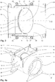
- Figure 3 shows a plan view of the valve 1 from above while Fig. 4a an oblique view shows and Fig. 4b an oblique view with partially hidden elements. Below are the 2 to 4b described together.
- the valve housing 3 is delimited by a flat end wall 10 arranged upstream and a flat end wall 11 arranged downstream.
- the end walls 10 and 11 are arranged perpendicular to the longitudinal plane A.
- the end walls 10 and 11 are connected in the longitudinal direction B via flat side walls 12 and 13 arranged parallel to the longitudinal plane A.
- a radius of curvature of the lateral surface section 14 corresponds to the radius of the tube taper 7 adjoining the valve housing 3, which merges flush with the lateral surface section 14 on the underside.
- the valve housing 3 is thus largely prismatic in the longitudinal direction B with a largely constant, U-shaped cross section. With respect to the longitudinal plane A, the valve housing 3 is essentially mirror-symmetrical. On an upper side of the valve housing 3 there is a rectangular access opening 19 e.g. designed for maintenance, which is limited by the end walls 10 and 11 and the side walls 12 and 13 and can be closed by a cover (not shown). Clamping screws 20 for releasably fastening the cover are arranged on the valve housing 3 at the access opening. Stand elements 28 are formed on the pipe section 2 and on the pipe taper 7, with which the valve 1 can be positioned on a stand base in an operationally ready orientation.
- the pipe section 2 protrudes from the outside through the end wall 10 into the valve housing 3. In a lower region, the pipe section 2 extends in the direction of B essentially through the entire valve housing 3 up to a plane of the end wall 11. At one longitudinal end outside the valve housing 3, the pipe section 2 has a connecting flange 15, with which the valve 1 can be connected upstream to a pipeline (not shown).
- the pipe taper 7 tapers away from the valve housing 3 in the longitudinal direction B.
- the end wall 11 is open to the entire cross section of the tube cone 7 connected to the valve housing 3.
- the tube taper 7 has a diameter perpendicular to the longitudinal direction B, which is larger than a corresponding diameter of the tube section 2.
- the Pipe tapers 7 At a longitudinal end remote from the housing, the Pipe tapers 7 have a diameter which corresponds to the diameter of the pipe section 2.
- the pipe taper 7 can be connected to the pipeline.
- Pipe section 2 and pipe taper 7 are arranged coaxially in the valve.
- a bearing 17 and 18 is formed on the inside of each of the side walls 12 and 13.
- the bearings 17 and 18 are designed and arranged in mirror symmetry with respect to the longitudinal plane A.
- a safety support 27 is arranged on each side wall 12 and 13 and engages in a recess 48 in the bearing 17 or 18 (see here Fig. 7 ).
- the safety support 27 serves to additionally support the bearing 17 or 18 on the valve housing 3 in the event of an explosion.
- the axle body 8 is mounted on the two bearings 17 and 18 on the valve housing 3.
- the axle body 8 thus projects transversely, ie perpendicular to the longitudinal plane A, through the valve housing 3 downstream of the passage opening 4.
- the flap plate 6 is firmly attached to the axle body 8.
- Fig. 2 shows the flap plate in the rest position, in which the plate plane D is arranged parallel to the opening plane C of the passage opening 4 of the pipe section 2.
- the flap plate 6 is designed as a disk-shaped body with an elliptical surface, which corresponds to a cross section of the passage opening 4 in the opening plane C.
- FIG. 3 shows a plan view of the valve 1 from above and Fig. 4 shows an oblique view of the valve 1, from the downstream to the end wall 5.
- Side walls 12 and 13, lateral surface section 14, end wall 11, tube cone 7 are not shown for the sake of clarity.
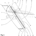
- FIG. 5 shows a schematic cross-sectional view of the flap plate 6 in the longitudinal plane A in the rest position (solid).
- the flap plate 6 is designed here as a laminated body with several layers of material. Upstream and downstream, the flap plate 6 has a layer 21 of conventional steel on the outside. A spring steel layer 22 is arranged between the steel layers 21. It goes without saying that a different choice of material for the layers 21 and 22 is also conceivable, which is why the exemplary embodiment described here is only to be understood as an example.
- the layers 21 and 22 are connected to one another point by point, so that sections of the layers 21 and 22 can be displaced relative to one another.
- the spring steel layer 22 projects over the entire circumference over the steel layers 21 on the edge in the plate plane D.
- the steel layers 21 are dimensioned such that they can be introduced into the passage opening 4 within the valve seat 5 when the flap plate 6 is arranged parallel to the opening plane C.
- the spring steel layer 22 thus provides the sealing surface 9 on the side of the passage opening 4. In this way, the flap plate 6 can be pressed into the passage opening 4 under the action of the closing pressure against the spring force of the spring steel layer 22.
- the flap plate 6 On a side facing away from the passage opening 4 in the rest position, the flap plate 6 has stiffening ribs 23, which are arranged perpendicular to the axle body 8 or the geometric axis of rotation E defined by it.
- the stiffening ribs 23 give the flap plate 6 additional mechanical stability with a lightweight and material-saving design.
- the axle body 8 is to the plate level D flattened out.
- the flap plate 6 can have a profile body 26 on the side facing away from the passage opening 4, which for example covers the axle body 8 and the stiffening ribs 23 (see also here Fig. 10 ).
- the profile body 26 can be designed, for example, according to a wing profile, so that the fluid flow F, in addition to the dynamic pressure, also generates a dynamic lift, which supports the opening movement into the operating position.
- the profile body 26 can be designed as a profile shell.
- the upper plate area 24 is at least partially pivoted into the passage opening 4 (see arrow).
- the lower area is pivoted away from the passage opening 4.
- the plate area 24 is dimensioned smaller than the plate area 25 due to the first eccentric position of the axle body 8. This ensures that the fluid flow F exerts an opening moment on the flap plate 6. It is also ensured that an explosion pressure wave X generates a closing torque.
- the flap plate 6 comes into the rest position due to the effect of gravity in the absence of an operating or closing pressure.
- Figure 6 schematically shows a possible schematic diagram of the bearing 17, which provides the sequential sequence of the mobility of the flap plate 6 described here.
- the bearing 17 comprises a preferably monolithic bearing body 30 (in Fig. 6 not shown, see e.g. Fig. 7 ), in which a recess 31 for a control body 32 is formed.
- the recess 31 forms a rotary guide for the control body 32 with a geometric axis of rotation G.
- the axis of rotation G coincides with the axis of rotation E of the axle body 8 when the control body 32 is guided in the rotary guide.
- the control body 32 is designed as a rod-shaped, largely prismatic body and is connected centrally to the axle body 8.
- a longitudinal direction of the control body 32 is arranged perpendicular to the axis of rotation E determined by the axle body 8.
- the axle body 8 is mounted in a longitudinal guide of the bearing body 30, which is designed as an elongated hole 33, so that it can rotate about its axis E and is guided such that it can move in the longitudinal direction L of the bearing 17.
- the longitudinal direction L is arranged parallel to B in the installed state of the bearing 17.
- the recess 31 is delimited in the radial direction by two circular-cylindrical lateral surface sections 34 arranged opposite one another with respect to the axis of rotation G.
- a distance between the lateral surface sections 34 corresponds (with a mobility tolerance) to a radial length of the control body 32, a radius of curvature corresponding to half the length of the control body 32.
- the lateral surface sections 34 thus form a radial slide bearing for the end faces of the control body 32.
- the end faces of the control body 32 are designed in accordance with a curvature of the lateral surface sections 34. As long as the control body 32 abuts both lateral surface sections 34, it is mounted in the rotary guide so as to be rotatable about the axis G.
- a bottom surface of the recess 31 forms a support in the axial direction along G.
- Two gable-shaped stops 35 are formed in the recess 31, which protrude into the recess with an apex directed towards the axis G.
- the stops 35 each have a stop surface 36 on one of their gable surfaces, which are aligned parallel to the bearing axis L. In their alignment along L, the stop surfaces 36 are at a distance which is a radial width of the control body 32 corresponds.
- the respective other gable surface of each stop 35 is designed analogously as a stop surface 37, which, however, is oriented perpendicular to the longitudinal direction L. The stop surfaces 36 and 37 thus limit the rotational movement of the control body 32 in both directions of rotation about the axis of rotation G to 90 degrees.
- a groove section 38 adjoins the recess 31.
- the groove section 38 has a cross section which corresponds to the cross section of the control body 32.
- the lateral guide surfaces 39 of the groove section 38 are aligned in the direction of L with the stop surfaces 36, one of the guide surfaces 39 smoothly merging into one of the stop surfaces 36.
- control body 32 If the control body 32 is in a rotational position in which it rests on the stop surfaces 36, it can thus be displaced in the groove section 38 in the longitudinal direction L.
- the axle body 8 is also displaced in the longitudinal guide 33.
- the stop surfaces 36 thus form a plain bearing for the linear movement of the control body 32 (see also here Fig. 10 ).
- the groove section 38 forms a linear guide of the bearing 17, which provides a linear mobility of the control body 32.
- Figure 7 shows a concrete implementation of the bearing 17 in a cross-sectional view in a plane parallel to the longitudinal plane A, which passes through the bearing 17.
- the bearing 18 has a mirror-inverted analog structure with respect to A.
- Fig. 6 For a description of the elements with reference numerals 30 to 39 is on Fig. 6 refer.
- the abutment surface 37 is arranged inclined with respect to the longitudinal direction L, so that the rotary movement in the rotary guide is limited to an angle less than 90 degrees.
- a roller bearing 40 in the form of roller bodies mounted in roller body cages is arranged on the stop surfaces 36.
- the stop surfaces 37 have roller bearing beds in the form of cutouts.
- the roller bearing 40 at the stop surface 36 which merges smoothly into one of the guide surfaces 39, extends into the groove section 38. It goes without saying that, depending on the requirement, no rolling bearings need to be present and the stop surfaces 36 can also be designed as simple plain bearings.
- a measuring bolt 41 protrudes into the groove section 38, which is mounted on the bearing body 30 so as to be displaceable in its longitudinal direction.
- the measuring pin 41 forms part of a measuring device for determining a position of the flap plate 6.
- the pin 41 is supported on the bearing body 30 by a series connection of two coil springs.
- the bolt 41 is shown in the Fig. 7 moved by the control body 32 into a first measuring position. The bolt 41 thus indicates a position of the control body 32 in which it can be introduced into the linear guide.
- the bolt 41 reaches a rest position in which it projects into the recess 31. If the control body 32 is moved into the linear guide, ie into the groove section 38, the pin 41 reaches a second measuring position. On the outside, the bolt 41 protrudes beyond the bearing body 30, with which a displacement state or a measuring position, for example, can be read or measured at an outer longitudinal end of the bolt 41.
- the lateral surface section 34 which adjoins the groove section 38, is in the present case formed on a bearing shoe 42.
- the guide surface 39 of the groove section 38 adjoining this lateral surface section 34 is formed on the bearing shoe 42.
- the bearing shoe 42 is mounted on the bearing body 30 so as to be displaceable in the direction of L. A displacement is achieved via a threaded spindle 43, which is supported on the bearing body 30 via a thread.
- the threaded spindle 43 is rotatably supported in the direction of L via an insert 44 of the bearing shoe 42.
- the insert 44 is loosely inserted into a recess in the bearing shoe 42.
- a locking body, designed as a ball 46, of a locking device is arranged in a recess 45.
- the recess 45 has a sloping bottom with respect to L, which is inclined away from L in the direction of displacement.
- the recess thus forms a barrier body bed.
- a spring-loaded pressure element supported on the bearing body 30 displaces the ball 46 in the recess 45 in the direction of the rotary guide.
- the inclined bottom of the recess 45 is dimensioned such that the ball 46 protrudes into the groove section 38 in a position close to the rotation guide and is arranged completely sunk in the recess 45 in a position remote from the rotation guide.
- the ball 46 deviates in the displacement direction. In the event of a displacement in the opposite direction, however, the ball 46 wedges between the control body 32 and the bearing shoe 42.
- the ball 46 thus forms part of a freewheel which interacts with the control body 32 in such a way that it is locked against displacement in the linear guide against the closing direction when it reaches the linear guide sufficiently far.
- the bearing shoe 42 forms part of a release device of the locking device.
- the bearing shoe 42 By moving the bearing shoe 42 towards the rotary guide, e.g. By actuating the threaded spindle 43, the wedging of the ball 46 can be released, whereby the control body 32 against the closing direction in the linear guide, i.e. i, groove section 38 can be moved.
- a recess 48 is also formed on the bearing body 30, into which a safety support of the valve housing 3 can engage.
- the safety support is provided in addition to fastening means 49 with which the bearing 17 is fastened in the valve housing 3 for regular operation.
- fastening means 49 with which the bearing 17 is fastened in the valve housing 3 for regular operation.
- the safety support arranged in the cutout 48 absorbs some of these forces and guides them into the valve housing 3. In this way, the forces on the bearing 17 can be distributed more evenly, without complicating the assembly of the bearing 17.
- Figure 8 shows selected elements of the valve 1, the flap plate 6 being arranged in an operating position.
- the control body 32 of the bearing 17 is rotated by G (and by E) up to the stop surfaces 37 in the recess 31 of the rotary guide.
- the bearing body 30 rests with an outside on an inside of the side wall 12, so that the guides and other components of the bearing 17 are covered.
- Figure 9a schematically shows another possible schematic diagram of a bearing 17 'for an explosion protection valve 1 according to the invention.
- An axle body 8 ' is in a longitudinal guide 33' on a bearing body 30 '(in Fig. 9a not shown, see here Fig. 9b ) displaceable in a longitudinal direction L 'of the bearing 17' and rotatably supported about its longitudinal axis E '.
- An eccentric to the axle body 8 'and rigidly connected to this control body 32' is guided in a curve 31 'on a partial circular path around an axis of rotation G'.
- the cam guide 31 'thus ensures via the control body 32' that the axle body 8 'can be rotated by G' and thus in this position by E ', but not in the longitudinal guide 33'.
- a longitudinal guide 38 ' adjoins the curved guide 31', which is arranged parallel to L 'and to the longitudinal guide 33'. As soon as the control body 32 'reaches the longitudinal guide 38', the axle body 8 'is locked against rotation, but can be moved in the longitudinal guide 33' in the longitudinal direction L '.
- the curve guide 31 'thus provides a rotary guide in the sense of the invention, while the longitudinal guide 38' accordingly forms a linear guide.
- the rotational movement and the linear movement of a flap plate 6 'rigidly connected to the axle body 8' can therefore only take place in succession.
- Figure 9b shows a specific embodiment of the bearing 17 '.
- the curve guide 31 ' is designed as a control surface as a bearing body 30', which forms only a one-sided guide surface for the control body 32 '.
- the longitudinal guide 38 ' is designed as a guide groove acting on both sides.
- the flap plate 6 ' is connected to the axle body 8' via a bearing block 29 '.
- the control body 32 ' is fixedly attached to the bearing block 29'.
- Figure 10 shows a largely the Fig. 8 corresponding view of the explosion protection valve 1, the stop surfaces 36 of the bearings 17 and 18 being designed as sliding surfaces for the control body 32.
- the bearing shoe 42 is also designed such that the lateral surface section 34 is only partially arranged on the bearing shoe 42.
- the remaining section 34, which is not arranged on the bearing shoe 42, is formed on the bearing body 30.
- the flap plate 6 according to the Fig. 10 the profile body 26 (see here Fig. 5 ), which is arranged on a downstream side of the flap plate 6 in the rest position.
- the flap plate is in contrast to the representation of the Fig. 8 in the rest position.
Landscapes
- Engineering & Computer Science (AREA)
- General Engineering & Computer Science (AREA)
- Mechanical Engineering (AREA)
- Health & Medical Sciences (AREA)
- Public Health (AREA)
- Business, Economics & Management (AREA)
- Emergency Management (AREA)
- Lift Valve (AREA)
Claims (11)
- Vanne à fermeture rapide contre les explosions (1), en particulier un clapet anti-retour pour le découplage des explosions, pour interrompre un écoulement de fluide (F), en particulier dans une canalisation, comprenant- un boîtier de soupape (3) avec une ouverture de passage (4) pour le passage du flux de fluide (F) et un siège de soupape (5) disposé à l'ouverture de passage (4),- un corps de fermeture (6), en particulier une plaque de clapet (6), avec une surface d'étanchéité (9), dans lequel- le corps de fermeture (6) est monté de manière mobile dans le boîtier de soupape (3) sur un palier (17, 17') de telle sorte qu'il est mobile au moins entre une position de repos, une position de fonctionnement et une position de fermeture, dans laquelle- le corps de fermeture (6) se trouve en position de repos en l'absence du flux de fluide (F), en position de fonctionnement l'ouverture de passage (4) est ouverte par le corps de fermeture et en position fermée l'ouverture de passage (4) est fermée par le corps de fermeture (6), le corps de fermeture (6) en position fermée reposant avec la surface d'étanchéité (9) contre le siège de soupape (5), dans lequel- le corps de fermeture (6) est déplaçable en position de fonctionnement sous l'action d'une pression de fonctionnement et déplaçable en position de fermeture sous l'action d'une pression de fermeture différente de la pression de fonctionnement, dans laquelle- le corps de fermeture (6) est arrêtable, de préférence automatiquement, en position fermée au moyen d'un dispositif de verrouillage, caractérisé en ce que
le palier (17, 17') de le corps de fermeture (6) est conçu de telle sorte que le corps de fermeture (6) est déplaçable dans le sens de la fermeture de la position de fonctionnement à la position de fermeture par un mouvement rotatif et un mouvement linéaire,
le palier (17, 17') étant conçu de telle sorte que le corps de fermeture (6), pour le passage de la position de fonctionnement à la position de fermeture, est mobile d'abord dans le mouvement de rotation et ensuite dans le mouvement linéaire, une position du corps de fermeture (6) correspondant de préférence à la position de repos lors du passage du mouvement de rotation au mouvement linéaire, le corps de fermeture (6) étant monté sur le palier (17, 17') par l'intermédiaire d'un corps d'essieu (8, 8'), de préférence un deuxième palier (18, 18') inversé en miroir, et les deux paliers (17, 17', 18, 18') étant disposés parallèlement l'un à l'autre des deux côtés de l'ouverture de passage (4), le corps de fermeture (6) étant monté sur les deux paliers (17, 17', 18, 18'),
dans lequel le palier (17, 17') comprend un guidage rotatif et un guidage linéaire pour un corps de commande (32, 32') relié rigidement au corps de fermeture (6) par l'intermédiaire du corps d'essieu (8, 8'), dans lequel le palier (17, 17') comprend en outre un guidage longitudinal (33, 33') dans lequel le corps d'essieu (8, 8') est guidé en rotation et en translation, dans lequel une direction de translation du guidage longitudinal (33, 33') est parallèle à la direction de translation du guidage linéaire pour le corps de commande (32, 32'). - Vanne à fermeture rapide contre les explosions (1) selon la revendication 1, caractérisée en ce que la surface d'étanchéité (9) du corps de fermeture (6) et le siège de soupape (5) sont formés à plat et sont alignés dans des plans parallèles l'un à l'autre lorsque le corps de fermeture (6) est mobile dans le mouvement linéaire.
- Vanne à fermeture rapide contre les explosions (1), selon l'une des revendications précédentes, caractérisée en ce que le corps de commande (32, 32') est disposé de manière centrale par rapport au corps d'essieu (8, 8').
- Vanne à fermeture rapide contre les explosions (1), selon l'une des revendications précédentes, caractérisée en ce que le guide rotatif et le guide linéaire sont conçus et disposés l'un par rapport à l'autre de telle manière que le corps de commande (32, 32') n'est déplaçable du guide rotatif dans le guide linéaire que dans une position de rotation prédéterminée.
- Vanne à fermeture rapide contre les explosions (1), selon la revendication 4, caractérisée en ce que le guide rotatif présente un évidement (31) dans lequel le corps de commande (32, 32'), guidé dans la direction radiale et/ou axiale, est rotatif au moins partiellement autour d'un axe géométrique de rotation (G, G') défini par le guide rotatif.
- Vanne à fermeture rapide contre les explosions (1), selon la revendication 5, caractérisée en ce que l'évidement (31) est au moins partiellement délimité dans la direction radiale par rapport à l'axe de rotation géométrique (G, G') par des sections de surface cylindriques circulaires (34) avec un rayon de courbure qui correspond à la moitié d'une dimension radiale du corps de commande (32, 32').
- Vanne à fermeture rapide contre les explosions (1), selon l'une des revendications 5 ou 6, caractérisée en ce que le guide linéaire comprend une section de rainure (38) qui est reliée dans la direction radiale à l'évidement (31) et dans laquelle le corps de commande (32, 32') est déplaçable dans la direction de déplacement du guide linéaire hors de l'évidement (31) du guide rotatif.
- Vanne à fermeture rapide contre les explosions (1), selon l'une des revendications 5 à 7, caractérisée en ce que dans l'évidement (31), au moins un élément de butée (35) est formé avec une surface de butée (36) qui limite le mouvement de rotation du corps de commande (32, 32') dans l'évidement (31) de telle sorte que le corps de commande (32, 32') est déplaçable dans le guidage linéaire lorsqu'il s'appuie sur la surface de butée (36), la surface de butée (36) étant en particulier, si nécessaire, alignée avec une surface de guidage (39) de la section de rainure (38).
- Vanne à fermeture rapide contre les explosions (1), selon l'une des revendications précédentes caractérisée en ce que le dispositif de verrouillage comprend une roue libre qui permet le mouvement du corps de fermeture (6) dans la direction de fermeture et le bloque dans la direction opposée, au moins lorsque le corps de fermeture (6) est en position fermée.
- Vanne à fermeture rapide contre les explosions (1), selon l'une des revendications précédentes, caractérisée en ce que l'ouverture de passage (4) est conçue comme une ouverture d'extrémité d'un manchon tubulaire (2) disposé au moins partiellement dans le boîtier de la soupape (3) et une face frontale du manchon tubulaire (2) disposé dans le boîtier de la soupape (3) forme le siège de la soupape (5).
- Vanne à fermeture rapide contre les explosions (1), selon l'une des revendications précédentes, caractérisée en ce que le corps de fermeture (6) est réalisé sous forme de plaque à clapet (6), en particulier à plat sur au moins un côté.
Applications Claiming Priority (1)
| Application Number | Priority Date | Filing Date | Title |
|---|---|---|---|
| PCT/EP2013/058153 WO2014169961A1 (fr) | 2013-04-19 | 2013-04-19 | Vanne de sécurité antidéflagrante |
Publications (2)
| Publication Number | Publication Date |
|---|---|
| EP2986876A1 EP2986876A1 (fr) | 2016-02-24 |
| EP2986876B1 true EP2986876B1 (fr) | 2020-07-29 |
Family
ID=48182896
Family Applications (1)
| Application Number | Title | Priority Date | Filing Date |
|---|---|---|---|
| EP13718317.4A Active EP2986876B1 (fr) | 2013-04-19 | 2013-04-19 | Vanne de sécurité antidéflagrante |
Country Status (3)
| Country | Link |
|---|---|
| US (1) | US10066752B2 (fr) |
| EP (1) | EP2986876B1 (fr) |
| WO (1) | WO2014169961A1 (fr) |
Families Citing this family (7)
| Publication number | Priority date | Publication date | Assignee | Title |
|---|---|---|---|---|
| DE102016122468B3 (de) * | 2016-11-22 | 2018-02-15 | Keller Lufttechnik Gmbh + Co. Kg | Vorrichtung zur explosionstechnischen Entkopplung zweier Anlagenteile einer Anlage |
| WO2018213820A1 (fr) * | 2017-05-19 | 2018-11-22 | Bs&B Innovations Limited | Soupape à clapet anti-explosion |
| CN108032225B (zh) * | 2017-12-05 | 2020-04-07 | 重庆北金人防工程设备有限公司 | 用于磨削车床的防爆吸尘装置 |
| JP6815367B2 (ja) * | 2018-11-19 | 2021-01-20 | アイシン精機株式会社 | 流路装置およびエンジン冷却システム |
| CN115264132A (zh) * | 2022-07-29 | 2022-11-01 | 广船国际有限公司 | 一种双向作用止回风闸 |
| CN116971866A (zh) * | 2023-08-03 | 2023-10-31 | 河南柴油机重工有限责任公司 | 一种自复位式气体发动机用排气防爆阀 |
| US20250155038A1 (en) * | 2023-11-10 | 2025-05-15 | Zurn Water, Llc | Check valve having pivoting link |
Citations (2)
| Publication number | Priority date | Publication date | Assignee | Title |
|---|---|---|---|---|
| US4605198A (en) * | 1985-01-28 | 1986-08-12 | Seal-Air Control Systems Inc. | Damper construction |
| US4667883A (en) * | 1984-12-17 | 1987-05-26 | Husky Corporation | Butterfly valve for fluid flow line |
Family Cites Families (18)
| Publication number | Priority date | Publication date | Assignee | Title |
|---|---|---|---|---|
| US3013579A (en) * | 1961-02-09 | 1961-12-19 | James P Gilliam | Flip poppet valve |
| US3677289A (en) | 1970-09-09 | 1972-07-18 | American Air Filter Co | Pressure relief valve |
| US3687157A (en) * | 1971-04-08 | 1972-08-29 | Jeff David Whitmer | Trap for drill pipe |
| US4353390A (en) * | 1979-12-06 | 1982-10-12 | Anchor/Darling Valve Company | Swing check valve with internally balanced disc |
| CA1140420A (fr) | 1979-12-06 | 1983-02-01 | Crane Canada Limited | Clapet de retenue |
| US4669500A (en) * | 1986-05-23 | 1987-06-02 | Wheatley Pump And Valve, Inc. | Check valve actuator |
| US5106052A (en) * | 1991-05-09 | 1992-04-21 | Dipti Datta | Air damper apparatus |
| US5305787A (en) * | 1993-02-03 | 1994-04-26 | C & S Valve Company | Disk valve with improved disk mounting |
| US5622205A (en) * | 1995-09-14 | 1997-04-22 | Petersen; Robert E. | Check valve having reserved mechanical closure |
| US6164324A (en) * | 1999-09-23 | 2000-12-26 | Edward Vogt Valve Company | Adjustable quick closing disk check value with flow indicator |
| US7784489B2 (en) | 2005-08-11 | 2010-08-31 | Envirotech Pumpsystems, Inc. | Check valve for a self-priming pump |
| US7533693B2 (en) * | 2005-10-31 | 2009-05-19 | Ga Industries, Llc | Side-mounted position indicator for flapper check valve |
| DE102007010060B3 (de) | 2007-03-01 | 2008-06-19 | Keller Lufttechnik Gmbh + Co. Kg | Vorrichtung zur explosionstechnischen Entkopplung zweier Anlagenteile |
| US20080308159A1 (en) * | 2007-06-15 | 2008-12-18 | Stunkard Gerald A | Top entry swing check valve |
| CH701035A1 (de) | 2009-05-14 | 2010-11-15 | Rico Sicherheitstechnik Ag | Explosionsschutzventil zum Unterbrechen eines Fluidstroms in einer Rohrleitung. |
| US8567431B2 (en) * | 2011-09-13 | 2013-10-29 | Philip L. Hapner | Check valve |
| US8869832B2 (en) * | 2012-03-14 | 2014-10-28 | Hans D Baumann | Variable resistance device |
| US8875733B2 (en) * | 2012-12-04 | 2014-11-04 | Douglas Hunter Powell | Check valve in backflow prevention device |
-
2013
- 2013-04-19 EP EP13718317.4A patent/EP2986876B1/fr active Active
- 2013-04-19 US US14/785,132 patent/US10066752B2/en active Active
- 2013-04-19 WO PCT/EP2013/058153 patent/WO2014169961A1/fr not_active Ceased
Patent Citations (2)
| Publication number | Priority date | Publication date | Assignee | Title |
|---|---|---|---|---|
| US4667883A (en) * | 1984-12-17 | 1987-05-26 | Husky Corporation | Butterfly valve for fluid flow line |
| US4605198A (en) * | 1985-01-28 | 1986-08-12 | Seal-Air Control Systems Inc. | Damper construction |
Also Published As
| Publication number | Publication date |
|---|---|
| US10066752B2 (en) | 2018-09-04 |
| EP2986876A1 (fr) | 2016-02-24 |
| WO2014169961A1 (fr) | 2014-10-23 |
| US20160061339A1 (en) | 2016-03-03 |
Similar Documents
| Publication | Publication Date | Title |
|---|---|---|
| EP0224516B1 (fr) | Element de fermeture pour tuyauterie | |
| DE3209217C2 (de) | Schiebeventil | |
| DE3224387C2 (fr) | ||
| DE4301403C2 (de) | Zentralverschluß für Mehrpunktsicherheitsgurte | |
| EP2986876A1 (fr) | Vanne de sécurité antidéflagrante | |
| DE2941451C2 (de) | Reibungsarme Dichtung für die Antriebsspindel von Hähnen und Ventilen | |
| AT509878B1 (de) | Saugventil mit abhebegreifer | |
| DE112013007622T5 (de) | Ventilbetätigungsanordnung mit einem Freilauf und einem axialen Reibmittel | |
| EP0277134B1 (fr) | Vanne a actionnement rapide | |
| WO2016155976A1 (fr) | Soupape à dépression | |
| EP2241792B1 (fr) | Double robinet-vanne | |
| EP2855985B1 (fr) | Vanne d'arrêt | |
| DE19526898A1 (de) | Verriegelungsvorrichtung für Fluiddruckzylinder | |
| EP4264093B1 (fr) | Ensemble soupape proportionnelle destiné à des fluides frigorigènes | |
| DE1961248C (fr) | ||
| EP0662575B1 (fr) | Mécanisme de vanne avec guidage forcé | |
| DE4307107C1 (de) | Vorrichtung zum Ver- und Entriegeln eines Pressenstößels | |
| EP4411183B1 (fr) | Unité coulissante d'une vanne | |
| DE60106534T2 (de) | Vorrichtung und einheit für die verriegelung der kolbenstange eines linearantriebes | |
| DE102007012292B3 (de) | Kontrollgerät mit Schaltfunktion für ohne Hilfsenergie und Hilfsgas arbeitende Sicherheitsabsperrventile verschiedener Baugrößen | |
| DE3909482A1 (de) | Ventil mit einer dichtung | |
| DE2011011B2 (de) | Schnellschlussventil mit einer kugelrasteinrichtung | |
| DE2403750A1 (de) | Absperrschieber | |
| CH676282A5 (en) | Hydraulically or pneumatically actuated slide valve | |
| DE1199079B (de) | Klappenventil |
Legal Events
| Date | Code | Title | Description |
|---|---|---|---|
| PUAI | Public reference made under article 153(3) epc to a published international application that has entered the european phase |
Free format text: ORIGINAL CODE: 0009012 |
|
| 17P | Request for examination filed |
Effective date: 20151029 |
|
| AK | Designated contracting states |
Kind code of ref document: A1 Designated state(s): AL AT BE BG CH CY CZ DE DK EE ES FI FR GB GR HR HU IE IS IT LI LT LU LV MC MK MT NL NO PL PT RO RS SE SI SK SM TR |
|
| AX | Request for extension of the european patent |
Extension state: BA ME |
|
| DAX | Request for extension of the european patent (deleted) | ||
| STAA | Information on the status of an ep patent application or granted ep patent |
Free format text: STATUS: EXAMINATION IS IN PROGRESS |
|
| 17Q | First examination report despatched |
Effective date: 20190108 |
|
| GRAP | Despatch of communication of intention to grant a patent |
Free format text: ORIGINAL CODE: EPIDOSNIGR1 |
|
| STAA | Information on the status of an ep patent application or granted ep patent |
Free format text: STATUS: GRANT OF PATENT IS INTENDED |
|
| INTG | Intention to grant announced |
Effective date: 20200408 |
|
| GRAS | Grant fee paid |
Free format text: ORIGINAL CODE: EPIDOSNIGR3 |
|
| GRAA | (expected) grant |
Free format text: ORIGINAL CODE: 0009210 |
|
| STAA | Information on the status of an ep patent application or granted ep patent |
Free format text: STATUS: THE PATENT HAS BEEN GRANTED |
|
| AK | Designated contracting states |
Kind code of ref document: B1 Designated state(s): AL AT BE BG CH CY CZ DE DK EE ES FI FR GB GR HR HU IE IS IT LI LT LU LV MC MK MT NL NO PL PT RO RS SE SI SK SM TR |
|
| REG | Reference to a national code |
Ref country code: GB Ref legal event code: FG4D Free format text: NOT ENGLISH |
|
| REG | Reference to a national code |
Ref country code: CH Ref legal event code: EP |
|
| REG | Reference to a national code |
Ref country code: DE Ref legal event code: R096 Ref document number: 502013014966 Country of ref document: DE |
|
| REG | Reference to a national code |
Ref country code: CH Ref legal event code: NV Representative=s name: HEPP WENGER RYFFEL AG, CH |
|
| REG | Reference to a national code |
Ref country code: AT Ref legal event code: REF Ref document number: 1296200 Country of ref document: AT Kind code of ref document: T Effective date: 20200815 |
|
| REG | Reference to a national code |
Ref country code: IE Ref legal event code: FG4D Free format text: LANGUAGE OF EP DOCUMENT: GERMAN |
|
| REG | Reference to a national code |
Ref country code: LT Ref legal event code: MG4D |
|
| REG | Reference to a national code |
Ref country code: NL Ref legal event code: MP Effective date: 20200729 |
|
| PG25 | Lapsed in a contracting state [announced via postgrant information from national office to epo] |
Ref country code: PT Free format text: LAPSE BECAUSE OF FAILURE TO SUBMIT A TRANSLATION OF THE DESCRIPTION OR TO PAY THE FEE WITHIN THE PRESCRIBED TIME-LIMIT Effective date: 20201130 Ref country code: NO Free format text: LAPSE BECAUSE OF FAILURE TO SUBMIT A TRANSLATION OF THE DESCRIPTION OR TO PAY THE FEE WITHIN THE PRESCRIBED TIME-LIMIT Effective date: 20201029 Ref country code: SE Free format text: LAPSE BECAUSE OF FAILURE TO SUBMIT A TRANSLATION OF THE DESCRIPTION OR TO PAY THE FEE WITHIN THE PRESCRIBED TIME-LIMIT Effective date: 20200729 Ref country code: FI Free format text: LAPSE BECAUSE OF FAILURE TO SUBMIT A TRANSLATION OF THE DESCRIPTION OR TO PAY THE FEE WITHIN THE PRESCRIBED TIME-LIMIT Effective date: 20200729 Ref country code: LT Free format text: LAPSE BECAUSE OF FAILURE TO SUBMIT A TRANSLATION OF THE DESCRIPTION OR TO PAY THE FEE WITHIN THE PRESCRIBED TIME-LIMIT Effective date: 20200729 Ref country code: HR Free format text: LAPSE BECAUSE OF FAILURE TO SUBMIT A TRANSLATION OF THE DESCRIPTION OR TO PAY THE FEE WITHIN THE PRESCRIBED TIME-LIMIT Effective date: 20200729 Ref country code: BG Free format text: LAPSE BECAUSE OF FAILURE TO SUBMIT A TRANSLATION OF THE DESCRIPTION OR TO PAY THE FEE WITHIN THE PRESCRIBED TIME-LIMIT Effective date: 20201029 Ref country code: GR Free format text: LAPSE BECAUSE OF FAILURE TO SUBMIT A TRANSLATION OF THE DESCRIPTION OR TO PAY THE FEE WITHIN THE PRESCRIBED TIME-LIMIT Effective date: 20201030 Ref country code: ES Free format text: LAPSE BECAUSE OF FAILURE TO SUBMIT A TRANSLATION OF THE DESCRIPTION OR TO PAY THE FEE WITHIN THE PRESCRIBED TIME-LIMIT Effective date: 20200729 |
|
| PG25 | Lapsed in a contracting state [announced via postgrant information from national office to epo] |
Ref country code: PL Free format text: LAPSE BECAUSE OF FAILURE TO SUBMIT A TRANSLATION OF THE DESCRIPTION OR TO PAY THE FEE WITHIN THE PRESCRIBED TIME-LIMIT Effective date: 20200729 Ref country code: RS Free format text: LAPSE BECAUSE OF FAILURE TO SUBMIT A TRANSLATION OF THE DESCRIPTION OR TO PAY THE FEE WITHIN THE PRESCRIBED TIME-LIMIT Effective date: 20200729 Ref country code: LV Free format text: LAPSE BECAUSE OF FAILURE TO SUBMIT A TRANSLATION OF THE DESCRIPTION OR TO PAY THE FEE WITHIN THE PRESCRIBED TIME-LIMIT Effective date: 20200729 Ref country code: IS Free format text: LAPSE BECAUSE OF FAILURE TO SUBMIT A TRANSLATION OF THE DESCRIPTION OR TO PAY THE FEE WITHIN THE PRESCRIBED TIME-LIMIT Effective date: 20201129 |
|
| PG25 | Lapsed in a contracting state [announced via postgrant information from national office to epo] |
Ref country code: NL Free format text: LAPSE BECAUSE OF FAILURE TO SUBMIT A TRANSLATION OF THE DESCRIPTION OR TO PAY THE FEE WITHIN THE PRESCRIBED TIME-LIMIT Effective date: 20200729 |
|
| PG25 | Lapsed in a contracting state [announced via postgrant information from national office to epo] |
Ref country code: EE Free format text: LAPSE BECAUSE OF FAILURE TO SUBMIT A TRANSLATION OF THE DESCRIPTION OR TO PAY THE FEE WITHIN THE PRESCRIBED TIME-LIMIT Effective date: 20200729 Ref country code: DK Free format text: LAPSE BECAUSE OF FAILURE TO SUBMIT A TRANSLATION OF THE DESCRIPTION OR TO PAY THE FEE WITHIN THE PRESCRIBED TIME-LIMIT Effective date: 20200729 Ref country code: IT Free format text: LAPSE BECAUSE OF FAILURE TO SUBMIT A TRANSLATION OF THE DESCRIPTION OR TO PAY THE FEE WITHIN THE PRESCRIBED TIME-LIMIT Effective date: 20200729 Ref country code: RO Free format text: LAPSE BECAUSE OF FAILURE TO SUBMIT A TRANSLATION OF THE DESCRIPTION OR TO PAY THE FEE WITHIN THE PRESCRIBED TIME-LIMIT Effective date: 20200729 Ref country code: SM Free format text: LAPSE BECAUSE OF FAILURE TO SUBMIT A TRANSLATION OF THE DESCRIPTION OR TO PAY THE FEE WITHIN THE PRESCRIBED TIME-LIMIT Effective date: 20200729 |
|
| REG | Reference to a national code |
Ref country code: DE Ref legal event code: R097 Ref document number: 502013014966 Country of ref document: DE |
|
| PG25 | Lapsed in a contracting state [announced via postgrant information from national office to epo] |
Ref country code: AL Free format text: LAPSE BECAUSE OF FAILURE TO SUBMIT A TRANSLATION OF THE DESCRIPTION OR TO PAY THE FEE WITHIN THE PRESCRIBED TIME-LIMIT Effective date: 20200729 |
|
| PLBE | No opposition filed within time limit |
Free format text: ORIGINAL CODE: 0009261 |
|
| STAA | Information on the status of an ep patent application or granted ep patent |
Free format text: STATUS: NO OPPOSITION FILED WITHIN TIME LIMIT |
|
| PG25 | Lapsed in a contracting state [announced via postgrant information from national office to epo] |
Ref country code: SK Free format text: LAPSE BECAUSE OF FAILURE TO SUBMIT A TRANSLATION OF THE DESCRIPTION OR TO PAY THE FEE WITHIN THE PRESCRIBED TIME-LIMIT Effective date: 20200729 |
|
| 26N | No opposition filed |
Effective date: 20210430 |
|
| PG25 | Lapsed in a contracting state [announced via postgrant information from national office to epo] |
Ref country code: SI Free format text: LAPSE BECAUSE OF FAILURE TO SUBMIT A TRANSLATION OF THE DESCRIPTION OR TO PAY THE FEE WITHIN THE PRESCRIBED TIME-LIMIT Effective date: 20200729 |
|
| PG25 | Lapsed in a contracting state [announced via postgrant information from national office to epo] |
Ref country code: MC Free format text: LAPSE BECAUSE OF FAILURE TO SUBMIT A TRANSLATION OF THE DESCRIPTION OR TO PAY THE FEE WITHIN THE PRESCRIBED TIME-LIMIT Effective date: 20200729 |
|
| GBPC | Gb: european patent ceased through non-payment of renewal fee |
Effective date: 20210419 |
|
| PG25 | Lapsed in a contracting state [announced via postgrant information from national office to epo] |
Ref country code: LU Free format text: LAPSE BECAUSE OF NON-PAYMENT OF DUE FEES Effective date: 20210419 |
|
| REG | Reference to a national code |
Ref country code: BE Ref legal event code: MM Effective date: 20210430 |
|
| PG25 | Lapsed in a contracting state [announced via postgrant information from national office to epo] |
Ref country code: GB Free format text: LAPSE BECAUSE OF NON-PAYMENT OF DUE FEES Effective date: 20210419 Ref country code: FR Free format text: LAPSE BECAUSE OF NON-PAYMENT OF DUE FEES Effective date: 20210430 |
|
| PG25 | Lapsed in a contracting state [announced via postgrant information from national office to epo] |
Ref country code: IE Free format text: LAPSE BECAUSE OF NON-PAYMENT OF DUE FEES Effective date: 20210419 |
|
| PG25 | Lapsed in a contracting state [announced via postgrant information from national office to epo] |
Ref country code: IS Free format text: LAPSE BECAUSE OF FAILURE TO SUBMIT A TRANSLATION OF THE DESCRIPTION OR TO PAY THE FEE WITHIN THE PRESCRIBED TIME-LIMIT Effective date: 20201129 |
|
| PG25 | Lapsed in a contracting state [announced via postgrant information from national office to epo] |
Ref country code: BE Free format text: LAPSE BECAUSE OF NON-PAYMENT OF DUE FEES Effective date: 20210430 |
|
| PG25 | Lapsed in a contracting state [announced via postgrant information from national office to epo] |
Ref country code: HU Free format text: LAPSE BECAUSE OF FAILURE TO SUBMIT A TRANSLATION OF THE DESCRIPTION OR TO PAY THE FEE WITHIN THE PRESCRIBED TIME-LIMIT; INVALID AB INITIO Effective date: 20130419 |
|
| PG25 | Lapsed in a contracting state [announced via postgrant information from national office to epo] |
Ref country code: CY Free format text: LAPSE BECAUSE OF FAILURE TO SUBMIT A TRANSLATION OF THE DESCRIPTION OR TO PAY THE FEE WITHIN THE PRESCRIBED TIME-LIMIT Effective date: 20200729 |
|
| PG25 | Lapsed in a contracting state [announced via postgrant information from national office to epo] |
Ref country code: MK Free format text: LAPSE BECAUSE OF FAILURE TO SUBMIT A TRANSLATION OF THE DESCRIPTION OR TO PAY THE FEE WITHIN THE PRESCRIBED TIME-LIMIT Effective date: 20200729 |
|
| PG25 | Lapsed in a contracting state [announced via postgrant information from national office to epo] |
Ref country code: TR Free format text: LAPSE BECAUSE OF FAILURE TO SUBMIT A TRANSLATION OF THE DESCRIPTION OR TO PAY THE FEE WITHIN THE PRESCRIBED TIME-LIMIT Effective date: 20200729 |
|
| PG25 | Lapsed in a contracting state [announced via postgrant information from national office to epo] |
Ref country code: MT Free format text: LAPSE BECAUSE OF FAILURE TO SUBMIT A TRANSLATION OF THE DESCRIPTION OR TO PAY THE FEE WITHIN THE PRESCRIBED TIME-LIMIT Effective date: 20200729 |
|
| REG | Reference to a national code |
Ref country code: CH Ref legal event code: U11 Free format text: ST27 STATUS EVENT CODE: U-0-0-U10-U11 (AS PROVIDED BY THE NATIONAL OFFICE) Effective date: 20260501 |
|
| PGFP | Annual fee paid to national office [announced via postgrant information from national office to epo] |
Ref country code: DE Payment date: 20260305 Year of fee payment: 14 |
|
| PGFP | Annual fee paid to national office [announced via postgrant information from national office to epo] |
Ref country code: AT Payment date: 20260325 Year of fee payment: 14 |
|
| PGFP | Annual fee paid to national office [announced via postgrant information from national office to epo] |
Ref country code: CH Payment date: 20260501 Year of fee payment: 14 |
|
| PGFP | Annual fee paid to national office [announced via postgrant information from national office to epo] |
Ref country code: CZ Payment date: 20260410 Year of fee payment: 14 |