EP2987257B1 - Réception d'une lumière codée en présence d'interférences - Google Patents
Réception d'une lumière codée en présence d'interférences Download PDFInfo
- Publication number
- EP2987257B1 EP2987257B1 EP14721530.5A EP14721530A EP2987257B1 EP 2987257 B1 EP2987257 B1 EP 2987257B1 EP 14721530 A EP14721530 A EP 14721530A EP 2987257 B1 EP2987257 B1 EP 2987257B1
- Authority
- EP
- European Patent Office
- Prior art keywords
- module
- interference
- receiver
- data
- light
- Prior art date
- Legal status (The legal status is an assumption and is not a legal conclusion. Google has not performed a legal analysis and makes no representation as to the accuracy of the status listed.)
- Not-in-force
Links
- 238000001228 spectrum Methods 0.000 claims description 50
- 230000003595 spectral effect Effects 0.000 claims description 46
- 230000000694 effects Effects 0.000 claims description 18
- 238000012545 processing Methods 0.000 claims description 9
- 230000000737 periodic effect Effects 0.000 claims description 8
- 238000000034 method Methods 0.000 claims description 7
- 230000007704 transition Effects 0.000 claims description 5
- 238000004590 computer program Methods 0.000 claims description 4
- 230000001131 transforming effect Effects 0.000 claims description 2
- 230000009466 transformation Effects 0.000 claims 2
- 238000005070 sampling Methods 0.000 description 30
- 230000002452 interceptive effect Effects 0.000 description 14
- 230000000873 masking effect Effects 0.000 description 8
- 238000005286 illumination Methods 0.000 description 5
- 238000001514 detection method Methods 0.000 description 4
- 238000010586 diagram Methods 0.000 description 4
- 238000004891 communication Methods 0.000 description 3
- 239000002131 composite material Substances 0.000 description 3
- 230000002238 attenuated effect Effects 0.000 description 2
- 230000008901 benefit Effects 0.000 description 2
- 230000001419 dependent effect Effects 0.000 description 2
- 238000012886 linear function Methods 0.000 description 2
- 238000013507 mapping Methods 0.000 description 2
- 230000003287 optical effect Effects 0.000 description 2
- 238000011084 recovery Methods 0.000 description 2
- 230000005540 biological transmission Effects 0.000 description 1
- 239000006227 byproduct Substances 0.000 description 1
- 230000008859 change Effects 0.000 description 1
- 238000012937 correction Methods 0.000 description 1
- 230000007423 decrease Effects 0.000 description 1
- 238000005516 engineering process Methods 0.000 description 1
- 238000001914 filtration Methods 0.000 description 1
- 230000000670 limiting effect Effects 0.000 description 1
- 230000000116 mitigating effect Effects 0.000 description 1
- 239000000203 mixture Substances 0.000 description 1
- 230000008569 process Effects 0.000 description 1
- 239000000047 product Substances 0.000 description 1
- 230000004044 response Effects 0.000 description 1
- 230000002441 reversible effect Effects 0.000 description 1
- 230000001629 suppression Effects 0.000 description 1
- 230000001360 synchronised effect Effects 0.000 description 1
Images




Classifications
-
- H—ELECTRICITY
- H04—ELECTRIC COMMUNICATION TECHNIQUE
- H04B—TRANSMISSION
- H04B10/00—Transmission systems employing electromagnetic waves other than radio-waves, e.g. infrared, visible or ultraviolet light, or employing corpuscular radiation, e.g. quantum communication
- H04B10/11—Arrangements specific to free-space transmission, i.e. transmission through air or vacuum
- H04B10/114—Indoor or close-range type systems
- H04B10/116—Visible light communication
-
- H—ELECTRICITY
- H04—ELECTRIC COMMUNICATION TECHNIQUE
- H04B—TRANSMISSION
- H04B10/00—Transmission systems employing electromagnetic waves other than radio-waves, e.g. infrared, visible or ultraviolet light, or employing corpuscular radiation, e.g. quantum communication
- H04B10/60—Receivers
- H04B10/61—Coherent receivers
- H04B10/616—Details of the electronic signal processing in coherent optical receivers
Definitions
- the present disclosure relates to interference that may be present when receiving coded visible light, and to mitigating an effect of such interference.
- Coded light refers to a technique whereby data is modulated into the visible illumination emitted by a light source, e.g. by an LED based luminaire.
- a light source e.g. by an LED based luminaire.
- the light source also acts as a transmitter capable of transmitting data to a suitable receiver of coded light.
- the modulation is typically performed at a high enough frequency that it is imperceptible to human vision, i.e. so the user only perceives the overall illumination and not the effect of the data being modulated into that illumination. In this way the data may be said to be embedded into the light from the light source.
- Coded light can be used in a number of applications. For instance, one application is to communicate between luminaires, e.g. as part of an intelligent lighting system.
- Each of a plurality of luminaires in an indoor or outdoor environment may be equipped with both a coded light transmitter and receiver, and the ability to communicate between them via coded light may be used to control the light in the environment in an at least partially distributed fashion.
- each luminaire may also be equipped with a presence sensor to detect presence of a being (typically a human), and information may be shared between two or more or the luminaires in order to determine how to control the light from the different luminaires in dependence on the detected presence.
- coded light may be used to provide information from a luminaire to a remote control unit for controlling that luminaire, e.g. to provide an identifier distinguishing it amongst other such luminaires which the remote unit can control, or to provide status information on the luminaire (e.g. to report errors, warnings, temperature, operating time, etc.).
- the remote control unit may comprise a mobile user terminal such as smart phone or tablet having an inbuilt camera or other light sensor. With the terminal running a suitable application, the user can direct the camera at a luminaire and thereby detect the identifier coded into the light from that luminaire. Given the identifier of the luminaire it is looking at, the terminal may then control that luminaire by sending back a return signal (e.g. via RF).
- the coded light may be used to provide information to a user, e.g. to provide identifiers of the luminaires for use in commissioning, or to enable provision of location related information.
- each luminaire in an indoor and/or outdoor environment e.g. in the rooms and corridors of an office complex, and/or paths of a campus
- the terminal can detect the identifier of a luminaire illuminating its current location.
- this may be used to look up information associated with the user's current location, such as information on exhibits in particular rooms of a museum.
- the look up may be performed via the Internet or a local network to which the terminal has access, or from a local database on the user terminal.
- the information could be directly coded into the light from one or more luminaires.
- the applicability of coded light is not limited.
- One way to implement coded light is by amplitude keying, by switching the amplitude or power of the emitted light between discrete levels in order to represent channel bits (or more generally channel symbols). For instance in the simplest case, when the light source is on (emitting) this represents a channel bit of value 1 and when the light source is off (not emitting) this represents a channel bit of value 0, or vice versa.
- a photo sensor in the coded light receiver can detect when the light is on or off, or distinguish between the different levels, and thereby receive the channel bits or symbols.
- the modulation typically involves a coding scheme to map data bits (sometimes referred to as user bits) onto channel bits.
- An example is a conventional Manchester code, which is a binary code whereby a user bit of value 0 is mapped onto a channel symbol off-on (channel bits 0 and then 1) and a user bit of value 1 is mapped onto a channel symbol on-off (channel bits 1 and then 0), or vice versa.
- the coding has at least two possible purposes. Firstly, as will be familiar to a person skilled in the art, in many coding schemes like Manchester coding, it allows the clock and data to be recovered from the same signal (otherwise a separate clock would have to be sent or the transmitter and receiver would have to be assumed to be perfectly synchronized). Secondly, it may have the effect of modifying the spectrum of the transmitted signal.
- coded light is susceptible to interference from certain low-frequency sources such as the mains power supply (50Hz or 60Hz in most countries).
- Existing coded light techniques attempt to avoid parts of the spectrum where interference occurs (sometimes referred to as spectral confinement). Codes such as the Manchester code may be chosen for their effect of suppressing the spectral density curve of the transmitted signal at lower frequencies, thus avoiding regions of low frequency interference.
- interference may originate from the backlight of a display screen which may be pulse width modulated in order to control its brightness.
- the pulse width modulation means the light output from the display takes the form of a constant or quasi-constant rectangular wave in the time domain, corresponding to a fundamental tone and a series of discrete harmonics in the frequency domain.
- pulse width modulation or sinusoidal modulation may be found in one or more other luminaires or light sources in the same environment, other than that emitting the desired data.
- the interference may even be one or more orders of magnitude stronger than the wanted signal, e.g. if the coded light sensor sees the interfering source directly whilst the wanted signal is only seen via a reflection from a surface such as a wall, floor or desk.
- the present invention provides for cancellation of potentially strong in-band interferers, such as PWM back lights or other periodic interferers.
- in-band interferers such as PWM back lights or other periodic interferers.
- interfering spikes such as found in the discrete tone spectrum of periodic interferers.
- a coded light receiver comprising a light sensor, a transform module, and an interference cancelling module.
- the sensor receives light having data modulated into it according to a coding scheme.
- the transform module is configured to transform the data into a frequency domain representation, representing a band of a spectrum resulting from said data being modulated into the light according to said coding scheme.
- the interference cancelling module is configured to cancel interference occurring in this band, by determining one or more components in the band that exceed a threshold signal strength and cancelling these components.
- a computer program product comprising code embodied on a computer readable medium and being configured so as when executed on a processor to operate a coded light receiver to perform interference cancelling in accordance with the disclosure herein.
- Figure 1 illustrates an example of an environment in which the interference cancelling disclosed herein may be employed, e.g. an office, home or other room or indoor space.
- the environment comprises a coded light transmitter 2 such as a luminaire, e.g. mounted on a ceiling or wall, installed for the primary purpose of illuminating the environment but also having the secondary function of providing data embedded into the illumination output using coded light techniques.
- the environment further comprises a coded light receiver 4.
- the coded light receiver 4 may be included in another luminaire, e.g. as part of an intelligent lighting system.
- the coded light receiver 4 may be a component of a remote control unit for controlling the transmitting luminaire 2, or of a user terminal such as mobile user terminal for deriving information from the transmitting luminaire 2 (such as location related information or information for use in commissioning).
- the light of the transmitting luminaire 2 reaches the receiver 4 via one or more reflections from one or more surfaces 8 such as the floor or walls.
- the received signal strength at the receiver 4 decreases.
- the visible light signal may be received with an amplitude of about 0.1 Lux.
- the interference is often in-band (e.g. between 0 and 4kHz), and the amplitude of the interference at the detector of the receiver 4 can be much larger than the signal amplitude at the extreme range of coded light communication (say 10 to 20 dB stronger, e.g. of the order of 1 Lux).
- the detector may "look" directly to the interference source 6 while the coded light is only seen indirectly via one or more reflections.
- the interference generated by such sources 6 may be periodic in nature, resulting in one or more distinct interfering tones in the spectrum of the coded light data being communicated from the transmitter 2.
- a pulse width modulated interferer 6 such as a PWM display screen will generate a rectangular wave in the time domain with a constant (or quasi constant) duty cycle.
- the signal received at the detector comprises a coded packet plus rectangular wave interference from a pulse width modulated source (in this example the PWM interference is at 240Hz, with the duty cycle 66%, signal-to-interference ratio -20 dB, and the packet present between 500 and 540ms).
- the transform e.g. Fourier transform
- the rectangular PWM interference corresponds to a series of narrow interfering tones or "spikes" in the frequency domain (e.g. see Figure 6 ).
- another luminaire or light source in the same environment may be modulated according to some other scheme such as being modulated with a sinusoid, thereby resulting in an interfering tone.
- the following embodiments are able to mitigate the effect of periodic interferers such as sinusoids or PWM-type of waveforms having a fixed (or quasi fixed) frequency and duty cycle in the band of interest, e.g. as in Figure 2 .
- the disclosed technique can reliably detect a physical layer coded light signal in the presence of an interferer which is 20 to 30 dB stronger than the coded light signal, or a mixture of interferers producing 20dB more interference power than the coded light signal.
- a threshold curve may be determined (e.g. "threshold 2") based on the expected power spectral density (or amplitude spectral density) associated with the coding scheme being used to code the light. Any component whose signal strength (power or amplitude) is a spike exceeding the threshold curve is assumed to be an interfering tone, and is excised by setting its power or amplitude to zero.
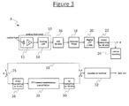
- FIG. 3 gives an example block diagram of a coded light receiver 4, configured to use frequency-domain interference excision in accordance with embodiments of the present disclosure.
- the receiver 4 comprises an analogue front-end 10, comprising a light sensor 12 and an analogue low pass filter (LPF) 14.
- the receiver further comprises an analogue to digital (AID) converter 16, a matched filter 18, a digital low pass filter (LPF) 20, a first down-sampling module 22, a carrier sensing module 24, a switch 25, a second down-sampling module 26, an interference cancellation module 28, an up-sampling module 30, a bypass path 31, and a baseband module 32.
- the light sensor 12 has an output coupled to an input of the analogue LPF 14.
- the analogue LPF 14 has an output coupled to an input of the A/D converter 16
- the A/D converter 16 has an output coupled to an input of the matched filter 18
- the matched filter 18 has an output coupled to an input of the digital LPF 20
- the digital LPF 20 has an output coupled to an input of the first down-sampling module 22
- the first down-sampling module 22 has an output coupled to an input of the carrier sensing module 24.
- the output of the first down-sampling module 26 is coupled to the baseband module 32 via the switch 25.
- the switch 25 When the switch 25 is asserted it couples the output of the first-down-sampling module 24 to an input of the second down-sampling module 26, and an output of the up-sampling module 30 to the input of the baseband module 32, with an output of the second down-sampling module 26 being coupled to an input of the interference cancellation module 28 and an output of the interference cancellation module 28 being coupled to an input of the up-sampling module 30.
- the switch 25 When the switch 25 is de-asserted, it couples the output of the first down-sampling module 24 directly to the input of the baseband module 32 via the bypass path 31, bypassing the second down-sampling module 26, interference cancellation module 28 and up-sampling module 30.
- Each of the digital components 18, 20, 22, 24, 26, 28, 30 and 32 may be implemented in software stored on a storage device of the receiver 4 and arranged for execution on a processor of the receiver 4. Alternatively some of all of these components may be implemented in dedicated hardware circuitry, or configurable hardware circuitry such as an FPGA, or a combination of software and hardware.
- the light sensor 12 receives incoming light comprising a coded light signal from the transmitter 2 and potentially interference from one or more interference sources 6.
- the coded light signal comprises data coded into the light using a coding scheme for coded light.
- the coding scheme used is one of the applicant's own creation and is referred to herein as a ternary Manchester code. This is illustrated in Figures 13 and 14 .
- each data bit to be transmitted is mapped to a composite channel symbol in the form of a respective pulse waveform, or "hat" function, as shown in Figure 13 .
- the pulse waveform mapped to a data bit of value 1 is shown on the left hand side of Figure 13
- the pulse waveform mapped to a data bit of value 0 is shown on the right hand side of Figure 13 .
- a data bit is a bit of actual information to be transmitted, sometimes referred to as "user data" (even if not explicitly created by a user).
- the data bit period is labeled T D in Figure 13 , with the boundaries between user bit periods shown with vertical dashed lines.
- the three elementary channel symbols for a respective data bit are contiguous, with the middle of the three being located at the center of the respective data bit period, so that the adjacent first and third elementary channel symbols straddle the beginning and end boundaries of the data bit period respectively by half an elementary channel symbol period T C either side.
- the positive hat function comprises: a first elementary channel symbol of amplitude -1 ⁇ 2 unit centered on the beginning (earlier) boundary of the respective data bit period, followed by second (middle) elementary channel symbol of amplitude +1 units being centered on the respective data bit period, followed by a third elementary channel symbol of amplitude -1 ⁇ 2 centered on the end (later) boundary of the respective data bit period.
- the negative hat function comprises: a first elementary channel symbol of amplitude +1 ⁇ 2 unit centered on the beginning (earlier) boundary of the respective data bit period, followed by second (middle) elementary channel symbol of amplitude -1 units being centered on the respective data bit period, followed by a third elementary channel symbol of amplitude +1 ⁇ 2 centered on the end (later) boundary of the respective data bit period.
- the hat functions of adjacent user bits are added to one another, offset by the locations of their respective bit periods along the time axis. Because the hat functions overlap across the boundaries between data bit periods, the functions add in the overlapping regions between adjacent data bits. That is, the hat functions are joined along the data bit period boundaries, so the earlier boundary A n of one data bit period is joined with the later bit boundary A n+1 of the preceding adjacent data bit period, with the level of the signal being summed where the two adjacent pulse waveforms overlap.
- An example of a resulting sequence of channel symbols in the time domain is shown in Figure 14 .
- mapping of data bit values 0 and 1 to positive and negative hat functions may be reversed.
- the resulting signal (e.g. that of Figure 14 ) is then converted into a variation in the signal strength output by the transmitting light source 2 (whether represented in terms of amplitude or power).
- elementary channel symbol -1 may be represented by a low light output level (e.g. light is turned off)
- the elementary channel symbol +1 may be represented by a high output light level (e.g. light is turned on)
- the elementary channel symbol 0 may be represented by an intermediate light level between the high and low (e.g. the light is at half the output power or amplitude).
- the ternary Manchester code can be advantageous as it provides a smoother transition when the data bits change value than a conventional Manchester code, and results in a spectrum in the frequency domain that is more suppressed around low frequencies where out-of-band interference such as mains hum may occur.
- the applicability of the present disclosure is not limited to ternary Manchester and in other embodiments other examples of suitable coding schemes may be used, e.g. a conventional (binary) Manchester code, or other conventional binary or ternary lines codes.
- the light sensor 12 at the receiver 4 detects the light and generates an electronic signal representative of the received light level (e.g. amplitude or power) as a function of time.
- the light sensor outputs this electronic signal through the analogue LPF 14 to the A/D converter 16 which samples it, e.g. at 64kHz, to produce a digital representation of the signal. Including effects of both coded light and interference, this results in a signal that might look for example something like Figure 2 .
- the A/D converter 16 outputs the digital version of the signal to the matched filter 18.
- the matched filter 18 acts to correlate a template waveform against the received signal.
- the template is a pulse waveform of the coding scheme being detected, e.g. in the case of the ternary Manchester code the template may be the positive hat function shown on the left-hand side of Figure 13 .
- the matched filter 18 passes its output to the digital LPF 20 where further low-pass filtering is applied, e.g. with a 4kHz pass band, and the digital LPF 20 passes the output of this to the first down-sampling module 22 where it is down-sampled, e.g. from 64kHz to 16kHz.
- the matched, filtered and down-sampled signal is then output to the switch 25.
- the interference cancellation is bypassed and the signal is output straight to the baseband receiver 32 for baseband processing.
- the baseband processing comprises functions such as carrier sense of power surge detection, clock generation, frame sync detection, and joint clock and data recovery. If the switch 25 is asserted on the other hand, the second down-sampling module, interference cancellation module 28 and up-sampling module 30 are switched into the chain prior to the baseband processing by the base band receiver module 32. In this case, the signal is output from the first down-sampling module 22 to the second down-sampling module 26 where it is further down-sampled, e.g. from 16kHz or 8kHz.
- This down-sampled signal is output from the second down-sampling module 26 to the interference cancellation module 28 which transforms the signal from the time domain to the frequency domain and performs frequency domain interference excision in accordance with embodiments of the present disclosure.
- the signal is then output from the interference cancellation module 28 to the up-sampling module 30 where it is up-sampled to reverse the down sampling by the second down-sampling module 26, e.g. back from 8kHz to 16kHz, then output onwards to the baseband module 32 for the baseband receive processing.
- the interference cancelling module 28 comprises a fast Fourier transform (FFT) filter 34, comprising a block selection module 38, a windowing module 40, a fast Fourier transform (FFT) module 42, a spectral masking module 44, an inverse FFT (IFFT) module 46, and an addition module 48.
- the interference cancelling module 28 further comprises a background processing module 36, comprising an absolute spectrum module 50, a threshold finder module 52, and a mask definition module 54.
- the block selection module 38 has an input arranged as the input of the interference cancelling module 28, coupled to the output of the second down-sampling module 26.
- the block selection module 38 has an output coupled to an input of the windowing module 40
- the windowing module 40 has an output coupled to an input of the FFT module 42
- the FFT module 42 has an output coupled to an input of the spectral masking module 44
- the spectral masking module 44 has an output coupled to an input of the IFFT module 46
- the IFFT 46 module has an output coupled to an input of the addition module 48.
- the addition module 48 has an output arranged as the output of the interference cancelling module 28, coupled to the input of the up-sampling module 30.
- the output of the FFT module 42 is coupled to an input of the absolute spectrum module 50, an output of the absolute spectrum module is coupled to an input of the threshold finder module 52, and output of the threshold finder module 52 is coupled to an input of the mask definition module 54, and an output of the mask definition module 54 is coupled to a further input of the spectral masking module 44.
- Each block of N samples is output to the windowing module 40 which applies a window function to each block respectively, e.g. a raised-cosine window function such as a Hamming window.
- the windowing module 40 outputs each windowed block to the FFT module 42, which transforms each block from the time domain into the frequency domain, thereby generating a frequency domain representation of each block.
- the frequency domain representation of a block comprises a plurality of spectral components, i.e. a measure of the signal at each of a plurality of frequency bins.
- the FFT module 42 passes the frequency domain representation of each block is passed from the FFT module 42 through the spectral masking module 44 which applies a spectral mask to excise interfering components.
- the frequency domain representation of each block is also output from the FFT module 42 to the absolute spectrum module 50 which determines the absolute spectrum of the transformed block, i.e. the absolute values of the components in the block without the effect of phase.
- the spectral components are represented in terms of the signal strength at each of a plurality of frequency bins (e.g. see Figures 5 and 6 ). In embodiments the signal strength may be represented in terms of power or amplitude (square root of power).
- the absolute spectrum module 50 outputs the absolute spectrum for the block to the threshold finder module 52 which uses it to determine a spectral density curve for the block, in embodiments either the power spectral density or amplitude spectral density as appropriate to the representation being used.
- the spectral density is the expected distribution of signal strength per unit frequency for an idealized random set of data.
- the shape of the spectral density curve is characteristic of the light coding scheme. So the shape of the spectral density curve for the ternary Manchester scheme will be different than that of a conventional, binary Manchester coding scheme, and different again from other coding schemes.
- the shape of the spectral density curve for ternary Manchester is shown schematically in Figure 7 , e.g. having a peak at 2kHz and a null at 4kHz.
- the spectral density is also scaled according to the integral of the absolute values of the components in the block - i.e. it represents the proportion of the block's power or amplitude that is expected as a function of frequency.
- the spectral density curve is dependent on the coding scheme being used to encode the light and on the total signal strength in the block (total power or amplitude).
- the threshold finder module 52 modifies the spectral density curve to determine a threshold curve (e.g. threshold 2 in Figure 6 ).
- the mask definition module 50 determines any components whose signal strength (power or amplitude) exceeds the threshold curve and defines a spectral mask which masks these components in the spectrum of the block.
- the mask definition module outputs the mask to the spectral masking module 44, which applies the mask so as to excise the masked components from the frequency domain representation of the respective block.
- the excision works on the basis that any spectral components having signal strength greater than the threshold mask (e.g. threshold 2 in Figure 6 ) are likely due (at least in a substantial part) to interfering tones from sources such as PWM luminaires or backlights.
- each block is passed from the spectral masking module 44 through the IFFT module 46 where the respective block is transformed back into the time domain.
- the IFFT module 46 outputs each block to the addition module 48 which adds overlapping regions of blocks together to produce a reconstructed time domain signal, but having interference been cancelled.
- the reconstructed, interference-cancelled time domain signal is then output onwards to the baseband module 32 where the baseband receive processing is performed.
- the interference excision is based on an observation that, in the frequency domain, it is possible to distinguish between the continuous spectrum of the wanted signal (resulting from the effectively random bits transmitted) and the discrete spectrum of periodic interferers.
- the user data is scrambled by a scrambling code so that the data retains a pseudo random quality regardless of the user data being transmitted. For example, even if the user transmits a stream of consecutive Is, or consecutive 0s, or some other data that results in an ordered stream of bits, the scrambled stream will still appear effectively random in that it will correspond to an approximately smooth spectrum in the frequency domain. However, even without scrambling most user data is still effectively random over a sufficiently large number of samples (even though the content may not be random, any order in the content does not necessarily manifest itself noticeably in the physical layer).
- coded light signal formats may not allow for strong signal restoration algorithms like error correction or spread spectrum.
- one or more of the following additional measures may optionally be implemented to further improve performance of the interference cancellation disclosed herein:
- interference excision is applied after the matched filter 18, but before the more traditional baseband receiver algorithms 32 such as carrier sense of power surge detection, clock generation, frame sync detection, and joint clock and data recovery.
- the analogue LPF 14 in the analogue front-end 10 is designed to be able to sample its output at 64kHz without having disturbing aliasing products.
- a matched filter 18 for ternary Manchester is first applied.
- the suppression of the signal at low frequencies helps to avoid low frequency (out-of band) interference from sources such as the mains power supply.
- an advantage of the placing of the matched filter 18 in the chain of Figure 3 is that the next null (in this example at 4kHz) can be arranged to coincide with the transition band for the subsequent digital LPF 20.
- the digital LPF 20 removes all frequencies above 4kHz, allowing for a down-sampling to 8kHz (according to the Nyquist theorem, to avoid aliasing distortion it is desirable to remove all frequencies that are more than half the sampling frequency).
- no low-pass filter is perfect and will in reality have a transition band 66 between the pass band 64 and stop band 68.
- the null at 4kHz (for example) can be arranged to be within the transition band 66 of the LPF 20.
- the interference excision described above involves transforming from the frequency domain to the time domain and back again. This implies it is desirable to have as wide a window as possible in the time domain, which implies wanting a sampling frequency as low as possible.
- the matched filter 18 before the LPF 20 it is known that the whole spectrum lies between 0Hz and 4kHz.
- interference excision takes place at 8kHz sampling frequency, corresponding to the baseband signal bandwidth of the ternary Manchester physical layer ( ⁇ 4kHz).
- each block is multiplied by a window function 40 in the form of a raised cosine window such as a Hamming window (raised cosine with roll-off of 1), the window being of width N in the time domain.
- a window function 40 in the form of a raised cosine window such as a Hamming window (raised cosine with roll-off of 1), the window being of width N in the time domain.
- Each block is then transformed to the frequency domain using an N-point FFT, resulting in an N-vector of frequencies.
- a multiplication in the time domain corresponds to a convolution in the frequency domain.
- a discrete interfering tone f i e.g. the fundamental or an harmonic of a rectangular wave due to PWM results in the convolution of a sinusoid with the window function.
- FIG. 10 An example of a rectangular window function 60 and a raised cosine window function 62 are shown schematically at the top of Figure 10 , and an example of a resulting convolution of a window function W with an interfering tone f i in the frequency domain is illustrated schematically at the bottom of Figure 10 . If the window is discontinuous at its edges, the width of the interfering tone goes with 1/f in the frequency domain; if the first derivative of the window is discontinuous at its edges, the width of this tone goes with 1/f 2 ; and if the second derivative is discontinuous the width of the tone goes with 1/f 3 .
- a raised-cosine window has this property.
- a Hamming window is a raised-cosine window parameterized by a roll-off of 1.
- the input is divided such that the blocks of N consecutive time samples are overlapping with one another.
- each block is given an overlap of N/2 samples with its neighboring blocks.
- the reason for this is illustrated schematically in Figure 11 .
- the non-rectangular window function has the effect that samples from the edge of the window in the time domain are attenuated.
- the overlapping regions are arranged to correspond to the regions in which the time domain signal is attenuated by the window function.
- the overlapping regions combine to undo an effect of the attenuation from the edges of the window function. In embodiments this will recover a flat function in the time domain.
- the interference cancelling module 28 may discard the first few and last few components of said N-vector of frequencies. This is because these components tend to be very erratic due to fixed point computations.
- the interference cancelling module 28 computes a frequency domain threshold curve as a scalar multiple of a standard threshold curve (the spectral density).
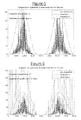
- Figure 5 shows the spectrum of a wanted signal and threshold masks with no interference.
- the random spectrum as computed using a 2048-point FFT applied to a Hamming-windowed portion (block) of received signal.
- a frequency domain threshold curve is computed that will distinguish between the continuous spectrum of the wanted signal and the discrete spectrum of interferers.
- the frequency domain threshold curve is a scaled version of the power spectral density of ternary Manchester, or a simplified approximation thereof.
- a raised cosine cantered at 1750 Hz is used as an approximation for the frequencies from 0 to 4kHz.
- the scaling of the frequency domain threshold curve is a linear function of the integral of the computed random spectrum.
- the scaling is such that in absence of interference, no frequency component crosses the threshold, i.e. no excision takes place.
- the actual frequency domain threshold curve used for excision is "threshold 2", since in embodiments the desired scaling (and frequencies to be excised) is determined in two steps.
- a scaling (leading to threshold 1) is obtained by taking a linear function of the integral of the absolute value of the computed random spectrum. That is, the theoretical (expected) spectral density curve for the relevant light coding scheme (e.g. ternary Manchester) is scaled by the total signal strength in the respective block (integral power or amplitude). This may also include a scaling by a certain factor to allow for a certain margin of error (i.e. in practice some legitimate signal components may fall slightly above the theoretical spectral density curve). In embodiments this factor may be 1.2 or 1.3.
- a second scaling is obtained by applying the same function to a modified absolute value of the computed random spectrum, where the modified absolute value of the computed random spectrum is obtained from the absolute value of the computed random spectrum by setting the spectral components larger than their "threshold 1" equal to zero. That is, the spectral density is now scaled by the total signal strength (integral power or amplitude) with the components falling beyond threshold 1 removed. This may also again include a scaling by a factor to allow a margin of error, e.g. again 1.2 or 1.3. The final excision takes place by setting frequency components equal to zero, whose absolute values are beyond "threshold 2".
- the step of applying a threshold, excising components and re-computing the threshold could be repeated again one or more times. I.e. there could be three steps leading to a "threshold 3", etc.
- each excised frequency block is transformed back to the time domain using an N-point IFFT, leading to an excised real N-vector in the time domain.
- the first few and last few components of said excised real N-vector in the time domain are set to zero, because these components tend to be very erratic due to fixed point computations.
- the resulting time domain vector is added to its corresponding place in the output time sequence.
- the coded light data may be transmitted in one or more packets, an example of which is illustrated in Figure 8 .
- the packet comprises a payload 58 comprising the user data discussed above, and also a header 56 comprising a preamble for use in synchronization.
- the payload 58 has a length of multiple of the blocks used in the interference cancellation above (e.g. 80 bytes of user data).
- the preamble comprises a clock signal which may comprise a plurality of cycles of a sinusoid (e.g. 20 cycles at 2kHz).
- a sinusoid e.g. 20 cycles at 2kHz
- the clock signal corresponds to the convolution of the sinusoid with the rectangular window function created by the length of the preamble (a sinusoid convolved with a rectangular window gives a sink function).
- This may have a spectral width of the order of 100 to 200Hz.
- the convolution of this same sinusoidal clock signal with the non-rectangular window function 40 corresponds to a much narrower spike being excised, perhaps of the order of 10Hz in width. Therefore it can be noted that in embodiments, as well as leaving the actual data 58 with negligible or tolerable distortion, the frequency excision discussed above need not destroy a clock signal 56 included in a packet preamble.
- the techniques disclosed herein are not limited to being implemented in terms of any particular measure of signal strength.
- signal strength may be expressed in in terms of power or amplitude.
- signal energy accumulated over a given time is a measure of power.
- energy spectral density in a finite window of time is a measure of power spectral density.
- Other ways of representing a signal in light may also be employed.
- the disclosure is not limited to any particular form of transform such as Fourier transform or FFT. Other kinds of transform will in themselves be familiar to a person skilled in the art, e.g. discrete cosine transform (DCT).
- DCT discrete cosine transform
- the interference cancellation comprises completely excising or masking spectral components, by setting their height to zero (setting the value representing strength to zero).
- the cancellation may comprise reducing the height of these components to reduce an effect of interference, rather than completely excising them.
- a computer program may be stored/distributed on a suitable medium, such as an optical storage medium or a solid-state medium supplied together with or as part of other hardware, but may also be distributed in other forms, such as via the Internet or other wired or wireless telecommunication systems. Any reference signs in the claims should not be construed as limiting the scope.
Landscapes
- Physics & Mathematics (AREA)
- Electromagnetism (AREA)
- Engineering & Computer Science (AREA)
- Computer Networks & Wireless Communication (AREA)
- Signal Processing (AREA)
- Optical Communication System (AREA)
- Arrangement Of Elements, Cooling, Sealing, Or The Like Of Lighting Devices (AREA)
Claims (15)
- Récepteur de lumière visible codée (4) comprenant :un capteur (12) pour recevoir de la lumière comprenant des données modulées en lumière selon un schéma de codage ;
etun module de transformation (42) configuré pour transformer les données en une représentation de domaine fréquentiel, représentant une bande d'un spectre résultant de la modulation desdites données en lumière selon ledit schéma de codage ; caractérisé parun module d'annulation d'interférence (28) configuré pour annuler l'interférence se produisant dans ladite bande, en déterminant une ou plusieurs composantes dans ladite bande qui dépassent une intensité de signal de seuil et en annulant lesdites composantes. - Appareil selon la revendication 1, dans lequel le seuil comprend une courbe dans le domaine fréquentiel, dans lequel ladite courbe est basée sur une densité spectrale étant caractéristique du schéma de codage utilisé pour moduler les données en la lumière.
- Appareil selon la revendication 2, dans lequel le module d'annulation d'interférence (28) est configuré pour effectuer lesdites détermination et annulation en :déterminant une première courbe de seuil sur la base de la densité spectrale, annulant une ou plusieurs premières composantes dépassant la première courbe de seuil, déterminant une seconde courbe de seuil sur la base de la densité spectrale excluant un effet des premières composantes, et pour annuler une ou plusieurs secondes composantes dépassant la seconde courbe de seuil.
- Appareil selon la revendication 3, dans lequel la première courbe de seuil est une version mise à l'échelle linéairement de la densité spectrale, et la seconde courbe de seuil est une version mise à l'échelle linéairement de la densité spectrale excluant l'effet desdites premières composantes.
- Récepteur selon l'une quelconque des revendications précédentes, dans lequel l'annulation comprend le réglage de l'intensité du signal desdites une ou plusieurs composantes à zéro.
- Récepteur selon l'une quelconque des revendications précédentes, comprenant un module en bande de base (32) et un module de transformation inverse (46) configuré pour retransformer les données en une représentation de domaine temporel en vue d'un traitement ultérieur par un module en bande de base après annulation de ladite interférence.
- Récepteur selon l'une quelconque des revendications précédentes, comprenant un filtre adapté (18) appliqué avant la transformation dans le domaine fréquentiel par le module de transformation (42).
- Récepteur selon l'une quelconque des revendications précédentes, comprenant en outre un filtre passe-bas (20), dans lequel le filtre adapté (18) est appliqué avant le filtre passe-bas et est configuré pour supprimer le spectre dans une bande de transition du filtre passe-bas.
- Récepteur selon l'une quelconque des revendications précédentes, comprenant un module de fenêtrage (40) configuré pour appliquer une fonction de fenêtre de domaine temporel avant la transformation en domaine fréquentiel par le module de transformation (42), divisant ainsi les données en parties ;
dans lequel le module de transformation (42) est configuré pour générer une représentation de domaine fréquentiel respective d'une bande du spectre résultant de chaque partie de données, et le module d'annulation d'interférence (28) est configuré pour fonctionner sur la représentation de domaine fréquentiel de chaque partie respectivement. - Récepteur selon la revendication 9, dans lequel le module de fenêtrage (40) est configuré pour diviser les données en une séquence de parties dans laquelle chaque partie comprend N échantillons de domaine temporel, et les parties successives se chevauchent sur une fraction des N échantillons.
- Récepteur selon la revendication 10, dans lequel ladite fonction de fenêtrage (40) comprend une fonction de fenêtrage en cosinus surélevé et ledit chevauchement est lié à un affaiblissement de la fonction de fenêtrage en cosinus surélevé.
- Récepteur selon l'une quelconque des revendications précédentes, dans lequel le module de transformation (42) est configuré pour éliminer les points d'extrémité de ladite bande dans le domaine fréquentiel avant l'annulation de l'interférence par ledit module d'annulation d'interférence (28).
- Récepteur selon l'une quelconque des revendications précédentes, comprenant un commutateur (25) utilisable pour contourner le module d'annulation d'interférence.
- Procédé d'utilisation d'un système d'éclairage comprenant :un luminaire (2) configuré pour émettre une lumière visible codée ;un dispositif comprenant le récepteur de lumière visible codée (4) selon l'une quelconque des revendications précédentes ; etau moins une source (6) de ladite interférence, l'interférence étant périodique dans le temps ;dans lequel au moins occasionnellement, l'interférence est reçue par le récepteur de lumière visible codée (4) avec au moins un ordre de grandeur d'intensité supérieur à la lumière comprenant lesdites données, et/ou la lumière comprenant lesdites données est reçue par le récepteur de lumière visible codée (4) via au moins une réflexion à partir d'au moins une surface (8) alors que l'interférence est reçue par le récepteur de lumière visible codée (4) directement.
- Programme informatique destiné à utiliser un récepteur de lumière visible codée (4), le produit de programme informatique comprenant un code intégré à un support de stockage lisible par ordinateur et configuré de telle sorte que lorsqu'il est exécuté, il permet d'exécuter les opérations suivantes :la réception, via un capteur (12) du récepteur de lumière visible codée, d'une lumière comprenant des données modulées en lumière selon un schéma de codage ;
etla transformation des données en une représentation de domaine fréquentiel, représentant une bande d'un spectre résultant de la modulation desdites données en lumière selon ledit schéma de codage ; caractérisé parl'annulation de l'interférence se produisant dans ladite bande, en déterminant une ou plusieurs composantes dans ladite bande qui dépassent une intensité de signal de seuil et en annulant lesdites composantes.
Priority Applications (1)
| Application Number | Priority Date | Filing Date | Title |
|---|---|---|---|
| EP14721530.5A EP2987257B1 (fr) | 2013-04-19 | 2014-04-10 | Réception d'une lumière codée en présence d'interférences |
Applications Claiming Priority (3)
| Application Number | Priority Date | Filing Date | Title |
|---|---|---|---|
| EP13164442 | 2013-04-19 | ||
| EP14721530.5A EP2987257B1 (fr) | 2013-04-19 | 2014-04-10 | Réception d'une lumière codée en présence d'interférences |
| PCT/IB2014/060615 WO2014170804A1 (fr) | 2013-04-19 | 2014-04-10 | Réception de lumière visible codée en présence de brouillage |
Publications (2)
| Publication Number | Publication Date |
|---|---|
| EP2987257A1 EP2987257A1 (fr) | 2016-02-24 |
| EP2987257B1 true EP2987257B1 (fr) | 2016-11-02 |
Family
ID=48141814
Family Applications (1)
| Application Number | Title | Priority Date | Filing Date |
|---|---|---|---|
| EP14721530.5A Not-in-force EP2987257B1 (fr) | 2013-04-19 | 2014-04-10 | Réception d'une lumière codée en présence d'interférences |
Country Status (6)
| Country | Link |
|---|---|
| US (2) | US9843386B2 (fr) |
| EP (1) | EP2987257B1 (fr) |
| JP (1) | JP6032779B2 (fr) |
| CN (1) | CN105122684B (fr) |
| ES (1) | ES2611472T3 (fr) |
| WO (1) | WO2014170804A1 (fr) |
Families Citing this family (15)
| Publication number | Priority date | Publication date | Assignee | Title |
|---|---|---|---|---|
| CN104050799B (zh) * | 2014-06-06 | 2017-03-08 | 北京智谷睿拓技术服务有限公司 | 反射控制方法及控制装置 |
| EP3216320B1 (fr) * | 2014-11-04 | 2018-04-04 | Philips Lighting Holding B.V. | Émetteur comportant une file d'attente de transmission et dispositif source correspondant |
| KR101688630B1 (ko) * | 2015-09-15 | 2016-12-21 | 한국전자통신연구원 | 키보드 장치 및 그것을 이용한 데이터 통신 방법 |
| US10282978B2 (en) | 2015-10-28 | 2019-05-07 | Abl Ip Holding, Llc | Visible light programming of daylight sensors and other lighting control devices |
| KR101864695B1 (ko) * | 2016-12-02 | 2018-06-05 | 서울과학기술대학교 산학협력단 | 가시광 통신에서 신호를 처리하는 방법 |
| JP7071626B2 (ja) * | 2018-03-19 | 2022-05-19 | 富士通株式会社 | 受信装置、通信システム、受信方法、及び受信プログラム |
| WO2020056402A1 (fr) * | 2018-09-14 | 2020-03-19 | Discrete Partners, Inc. | Émetteur-récepteur à spectre discret |
| US10938444B2 (en) * | 2019-07-12 | 2021-03-02 | Avago Technologies International Sales Pte. Limited | Apparatus and method for noise reduction in a full duplex repeater |
| US11328564B2 (en) | 2019-08-31 | 2022-05-10 | Appleton Grp Llc | Event indications of hazardous environment luminaires using visual sequences |
| US11232684B2 (en) | 2019-09-09 | 2022-01-25 | Appleton Grp Llc | Smart luminaire group control using intragroup communication |
| US11219112B2 (en) | 2019-09-09 | 2022-01-04 | Appleton Grp Llc | Connected controls infrastructure |
| US11343898B2 (en) | 2019-09-20 | 2022-05-24 | Appleton Grp Llc | Smart dimming and sensor failure detection as part of built in daylight harvesting inside the luminaire |
| US11438880B2 (en) * | 2019-11-22 | 2022-09-06 | Qualcomm Incorporated | Boundary identification for probabilistic amplitude shaping |
| CN111211836B (zh) * | 2020-01-09 | 2021-04-20 | 中国人民解放军战略支援部队信息工程大学 | 对称载波消除光通信方法、可见光收发器及可见光通信终端 |
| CN115437604B (zh) * | 2022-08-11 | 2026-04-17 | 中国电信股份有限公司 | 一种随机数生成方法、装置、电子设备及存储介质 |
Family Cites Families (16)
| Publication number | Priority date | Publication date | Assignee | Title |
|---|---|---|---|---|
| JPS5859497A (ja) * | 1981-10-05 | 1983-04-08 | 日本電信電話株式会社 | 音声認識装置 |
| US4507794A (en) | 1983-05-04 | 1985-03-26 | Jones Stephen K | Filtered Manchester Coded PSK transmission system |
| JP2830276B2 (ja) * | 1990-01-18 | 1998-12-02 | 松下電器産業株式会社 | 信号処理装置 |
| JPH05344071A (ja) * | 1991-02-19 | 1993-12-24 | Sharp Corp | 赤外線リモートコントロール用受光装置 |
| JPH07183849A (ja) * | 1993-12-22 | 1995-07-21 | N T T Data Tsushin Kk | 光空間伝送方法及び装置 |
| US8457178B2 (en) * | 2007-03-26 | 2013-06-04 | Qualcomm Incorporated | Frequency offset estimator |
| JP5185087B2 (ja) | 2008-11-25 | 2013-04-17 | 三星電子株式会社 | 可視光通信システム、及び信号伝送方法 |
| JP5410812B2 (ja) * | 2009-03-31 | 2014-02-05 | 三星電子株式会社 | 無線通信装置、無線通信システム、及び直接波の受信タイミング検出方法 |
| JP2011142581A (ja) * | 2010-01-08 | 2011-07-21 | Fujitsu Optical Components Ltd | 光通信方法、光通信システム、光信号受信装置及び光信号送信装置 |
| CN102696280B (zh) * | 2010-01-15 | 2016-07-06 | 皇家飞利浦电子股份有限公司 | 使用常规相机传感器针对可见光通信的数据检测 |
| ES2668280T3 (es) * | 2010-10-20 | 2018-05-17 | Philips Lighting Holding B.V. | Modulación para transmisión de luz codificada |
| CN103210602A (zh) * | 2010-11-01 | 2013-07-17 | 日本电气株式会社 | 相干光接收设备、系统和方法 |
| CN102684819B (zh) * | 2011-03-15 | 2015-06-03 | 华为技术有限公司 | 一种数据传输方法及相关设备、系统 |
| US9026064B2 (en) * | 2011-05-20 | 2015-05-05 | Telefonaktiebolaget L M Ericsson (Publ) | Dynamic cancellation of passive intermodulation interference |
| GB2496379A (en) * | 2011-11-04 | 2013-05-15 | Univ Edinburgh | A freespace optical communication system which exploits the rolling shutter mechanism of a CMOS camera |
| EP2940893B1 (fr) * | 2012-12-27 | 2021-05-19 | Panasonic Intellectual Property Corporation of America | Procédé de communication d'informations |
-
2014
- 2014-04-10 EP EP14721530.5A patent/EP2987257B1/fr not_active Not-in-force
- 2014-04-10 WO PCT/IB2014/060615 patent/WO2014170804A1/fr not_active Ceased
- 2014-04-10 JP JP2016508260A patent/JP6032779B2/ja not_active Expired - Fee Related
- 2014-04-10 US US14/785,420 patent/US9843386B2/en not_active Expired - Fee Related
- 2014-04-10 CN CN201480022175.0A patent/CN105122684B/zh not_active Expired - Fee Related
- 2014-04-10 ES ES14721530.5T patent/ES2611472T3/es active Active
-
2017
- 2017-10-19 US US15/788,159 patent/US10454578B2/en not_active Expired - Fee Related
Also Published As
| Publication number | Publication date |
|---|---|
| ES2611472T3 (es) | 2017-05-09 |
| US20180041274A1 (en) | 2018-02-08 |
| CN105122684A (zh) | 2015-12-02 |
| JP2016517238A (ja) | 2016-06-09 |
| US20160087719A1 (en) | 2016-03-24 |
| EP2987257A1 (fr) | 2016-02-24 |
| WO2014170804A1 (fr) | 2014-10-23 |
| JP6032779B2 (ja) | 2016-11-30 |
| CN105122684B (zh) | 2018-03-02 |
| US9843386B2 (en) | 2017-12-12 |
| US10454578B2 (en) | 2019-10-22 |
Similar Documents
| Publication | Publication Date | Title |
|---|---|---|
| US10454578B2 (en) | Receiving coded visible light in presence of interference | |
| RU2550497C2 (ru) | Передача и прием кодированного света | |
| Tsiatmas et al. | An illumination perspective on visible light communications | |
| CN105393474B (zh) | 编码光分量的调制 | |
| JP6009450B2 (ja) | 符号化光送信のための変調 | |
| CN105191180B (zh) | 从自计时编码光信号恢复时序 | |
| Singh et al. | Performance evaluation of IEEE 802.15. 7 CSK physical layer | |
| US20200204256A1 (en) | Led module for emitting signals | |
| US20090310973A1 (en) | Electroluminescent Emission Device for Optical Transmission in Free Space | |
| US20170148310A1 (en) | Detection of coded light | |
| Park et al. | Hadamard matrix design for a low-cost indoor positioning system in visible light communication | |
| EP3593598B1 (fr) | Atténuation de distorsion dans une lumière codée | |
| Dhaam et al. | Optical GFDM for indoor visible light communication: a comprehensive review and future outlook | |
| Yang et al. | Illumination sensing in LED lighting systems based on frequency-division multiplexing | |
| CN106797234A (zh) | 用于电力线通信的干扰检测和消除 | |
| Li et al. | Spatial superimposition-based PAPR reduction for UACO-OFDM systems with multiple LEDs | |
| US20250016900A1 (en) | Lighting apparatus | |
| Huang et al. | System design for wavelet packet division multiplexing-based visible light communications | |
| Durukan et al. | A novel CSK modulated OFDM system for visible light communication | |
| Deepthi et al. | An Energy Efficient Based Enhanced Optical OFDM for SISO and MIMO Visible Light Communication System in Indoor Environment | |
| Chen et al. | MPPM dimming control for OFDM-based visible light communication systems | |
| Saied | Orthogonal frequency division multiplexing for indoor visible light communication links | |
| Islam | Analytical model for the required DC bias for OFDM based LiFi | |
| Huang et al. | Visible light communication based on wavelet packet division multiplexing | |
| Malsugenov et al. | Improving Efficiency of a Wireless Optical Data Transmission Channel in the Visible Wavelengh Range |
Legal Events
| Date | Code | Title | Description |
|---|---|---|---|
| PUAI | Public reference made under article 153(3) epc to a published international application that has entered the european phase |
Free format text: ORIGINAL CODE: 0009012 |
|
| 17P | Request for examination filed |
Effective date: 20151119 |
|
| AK | Designated contracting states |
Kind code of ref document: A1 Designated state(s): AL AT BE BG CH CY CZ DE DK EE ES FI FR GB GR HR HU IE IS IT LI LT LU LV MC MK MT NL NO PL PT RO RS SE SI SK SM TR |
|
| AX | Request for extension of the european patent |
Extension state: BA ME |
|
| GRAP | Despatch of communication of intention to grant a patent |
Free format text: ORIGINAL CODE: EPIDOSNIGR1 |
|
| DAX | Request for extension of the european patent (deleted) | ||
| INTG | Intention to grant announced |
Effective date: 20160602 |
|
| RAP1 | Party data changed (applicant data changed or rights of an application transferred) |
Owner name: PHILIPS LIGHTING HOLDING B.V. |
|
| GRAS | Grant fee paid |
Free format text: ORIGINAL CODE: EPIDOSNIGR3 |
|
| GRAA | (expected) grant |
Free format text: ORIGINAL CODE: 0009210 |
|
| AK | Designated contracting states |
Kind code of ref document: B1 Designated state(s): AL AT BE BG CH CY CZ DE DK EE ES FI FR GB GR HR HU IE IS IT LI LT LU LV MC MK MT NL NO PL PT RO RS SE SI SK SM TR |
|
| REG | Reference to a national code |
Ref country code: GB Ref legal event code: FG4D |
|
| REG | Reference to a national code |
Ref country code: AT Ref legal event code: REF Ref document number: 842762 Country of ref document: AT Kind code of ref document: T Effective date: 20161115 Ref country code: CH Ref legal event code: EP |
|
| REG | Reference to a national code |
Ref country code: IE Ref legal event code: FG4D |
|
| REG | Reference to a national code |
Ref country code: DE Ref legal event code: R096 Ref document number: 602014004644 Country of ref document: DE |
|
| PG25 | Lapsed in a contracting state [announced via postgrant information from national office to epo] |
Ref country code: LV Free format text: LAPSE BECAUSE OF FAILURE TO SUBMIT A TRANSLATION OF THE DESCRIPTION OR TO PAY THE FEE WITHIN THE PRESCRIBED TIME-LIMIT Effective date: 20161102 |
|
| REG | Reference to a national code |
Ref country code: NL Ref legal event code: MP Effective date: 20161102 |
|
| REG | Reference to a national code |
Ref country code: LT Ref legal event code: MG4D |
|
| REG | Reference to a national code |
Ref country code: AT Ref legal event code: MK05 Ref document number: 842762 Country of ref document: AT Kind code of ref document: T Effective date: 20161102 |
|
| PG25 | Lapsed in a contracting state [announced via postgrant information from national office to epo] |
Ref country code: LT Free format text: LAPSE BECAUSE OF FAILURE TO SUBMIT A TRANSLATION OF THE DESCRIPTION OR TO PAY THE FEE WITHIN THE PRESCRIBED TIME-LIMIT Effective date: 20161102 Ref country code: GR Free format text: LAPSE BECAUSE OF FAILURE TO SUBMIT A TRANSLATION OF THE DESCRIPTION OR TO PAY THE FEE WITHIN THE PRESCRIBED TIME-LIMIT Effective date: 20170203 Ref country code: NL Free format text: LAPSE BECAUSE OF FAILURE TO SUBMIT A TRANSLATION OF THE DESCRIPTION OR TO PAY THE FEE WITHIN THE PRESCRIBED TIME-LIMIT Effective date: 20161102 Ref country code: NO Free format text: LAPSE BECAUSE OF FAILURE TO SUBMIT A TRANSLATION OF THE DESCRIPTION OR TO PAY THE FEE WITHIN THE PRESCRIBED TIME-LIMIT Effective date: 20170202 Ref country code: SE Free format text: LAPSE BECAUSE OF FAILURE TO SUBMIT A TRANSLATION OF THE DESCRIPTION OR TO PAY THE FEE WITHIN THE PRESCRIBED TIME-LIMIT Effective date: 20161102 |
|
| REG | Reference to a national code |
Ref country code: FR Ref legal event code: PLFP Year of fee payment: 4 |
|
| REG | Reference to a national code |
Ref country code: ES Ref legal event code: FG2A Ref document number: 2611472 Country of ref document: ES Kind code of ref document: T3 Effective date: 20170509 |
|
| PG25 | Lapsed in a contracting state [announced via postgrant information from national office to epo] |
Ref country code: PT Free format text: LAPSE BECAUSE OF FAILURE TO SUBMIT A TRANSLATION OF THE DESCRIPTION OR TO PAY THE FEE WITHIN THE PRESCRIBED TIME-LIMIT Effective date: 20170302 Ref country code: AT Free format text: LAPSE BECAUSE OF FAILURE TO SUBMIT A TRANSLATION OF THE DESCRIPTION OR TO PAY THE FEE WITHIN THE PRESCRIBED TIME-LIMIT Effective date: 20161102 Ref country code: PL Free format text: LAPSE BECAUSE OF FAILURE TO SUBMIT A TRANSLATION OF THE DESCRIPTION OR TO PAY THE FEE WITHIN THE PRESCRIBED TIME-LIMIT Effective date: 20161102 Ref country code: FI Free format text: LAPSE BECAUSE OF FAILURE TO SUBMIT A TRANSLATION OF THE DESCRIPTION OR TO PAY THE FEE WITHIN THE PRESCRIBED TIME-LIMIT Effective date: 20161102 Ref country code: HR Free format text: LAPSE BECAUSE OF FAILURE TO SUBMIT A TRANSLATION OF THE DESCRIPTION OR TO PAY THE FEE WITHIN THE PRESCRIBED TIME-LIMIT Effective date: 20161102 Ref country code: RS Free format text: LAPSE BECAUSE OF FAILURE TO SUBMIT A TRANSLATION OF THE DESCRIPTION OR TO PAY THE FEE WITHIN THE PRESCRIBED TIME-LIMIT Effective date: 20161102 Ref country code: IS Free format text: LAPSE BECAUSE OF FAILURE TO SUBMIT A TRANSLATION OF THE DESCRIPTION OR TO PAY THE FEE WITHIN THE PRESCRIBED TIME-LIMIT Effective date: 20170302 |
|
| PG25 | Lapsed in a contracting state [announced via postgrant information from national office to epo] |
Ref country code: DK Free format text: LAPSE BECAUSE OF FAILURE TO SUBMIT A TRANSLATION OF THE DESCRIPTION OR TO PAY THE FEE WITHIN THE PRESCRIBED TIME-LIMIT Effective date: 20161102 Ref country code: CZ Free format text: LAPSE BECAUSE OF FAILURE TO SUBMIT A TRANSLATION OF THE DESCRIPTION OR TO PAY THE FEE WITHIN THE PRESCRIBED TIME-LIMIT Effective date: 20161102 Ref country code: EE Free format text: LAPSE BECAUSE OF FAILURE TO SUBMIT A TRANSLATION OF THE DESCRIPTION OR TO PAY THE FEE WITHIN THE PRESCRIBED TIME-LIMIT Effective date: 20161102 Ref country code: SK Free format text: LAPSE BECAUSE OF FAILURE TO SUBMIT A TRANSLATION OF THE DESCRIPTION OR TO PAY THE FEE WITHIN THE PRESCRIBED TIME-LIMIT Effective date: 20161102 Ref country code: RO Free format text: LAPSE BECAUSE OF FAILURE TO SUBMIT A TRANSLATION OF THE DESCRIPTION OR TO PAY THE FEE WITHIN THE PRESCRIBED TIME-LIMIT Effective date: 20161102 |
|
| REG | Reference to a national code |
Ref country code: DE Ref legal event code: R097 Ref document number: 602014004644 Country of ref document: DE |
|
| RIN2 | Information on inventor provided after grant (corrected) |
Inventor name: BAGGEN, CONSTANT PAUL MARIE JOZEF Inventor name: VAN VOORTHUISEN, PAUL HENRICUS JOHANNES MARIA Inventor name: WITBERG, ERIK Inventor name: YANG, HONGMING |
|
| PG25 | Lapsed in a contracting state [announced via postgrant information from national office to epo] |
Ref country code: BE Free format text: LAPSE BECAUSE OF FAILURE TO SUBMIT A TRANSLATION OF THE DESCRIPTION OR TO PAY THE FEE WITHIN THE PRESCRIBED TIME-LIMIT Effective date: 20161102 Ref country code: SM Free format text: LAPSE BECAUSE OF FAILURE TO SUBMIT A TRANSLATION OF THE DESCRIPTION OR TO PAY THE FEE WITHIN THE PRESCRIBED TIME-LIMIT Effective date: 20161102 Ref country code: BG Free format text: LAPSE BECAUSE OF FAILURE TO SUBMIT A TRANSLATION OF THE DESCRIPTION OR TO PAY THE FEE WITHIN THE PRESCRIBED TIME-LIMIT Effective date: 20170202 |
|
| PLBE | No opposition filed within time limit |
Free format text: ORIGINAL CODE: 0009261 |
|
| STAA | Information on the status of an ep patent application or granted ep patent |
Free format text: STATUS: NO OPPOSITION FILED WITHIN TIME LIMIT |
|
| 26N | No opposition filed |
Effective date: 20170803 |
|
| PG25 | Lapsed in a contracting state [announced via postgrant information from national office to epo] |
Ref country code: SI Free format text: LAPSE BECAUSE OF FAILURE TO SUBMIT A TRANSLATION OF THE DESCRIPTION OR TO PAY THE FEE WITHIN THE PRESCRIBED TIME-LIMIT Effective date: 20161102 |
|
| REG | Reference to a national code |
Ref country code: CH Ref legal event code: PL |
|
| REG | Reference to a national code |
Ref country code: IE Ref legal event code: MM4A |
|
| PG25 | Lapsed in a contracting state [announced via postgrant information from national office to epo] |
Ref country code: MC Free format text: LAPSE BECAUSE OF FAILURE TO SUBMIT A TRANSLATION OF THE DESCRIPTION OR TO PAY THE FEE WITHIN THE PRESCRIBED TIME-LIMIT Effective date: 20161102 |
|
| PG25 | Lapsed in a contracting state [announced via postgrant information from national office to epo] |
Ref country code: CH Free format text: LAPSE BECAUSE OF NON-PAYMENT OF DUE FEES Effective date: 20170430 Ref country code: LU Free format text: LAPSE BECAUSE OF NON-PAYMENT OF DUE FEES Effective date: 20170410 Ref country code: LI Free format text: LAPSE BECAUSE OF NON-PAYMENT OF DUE FEES Effective date: 20170430 |
|
| PG25 | Lapsed in a contracting state [announced via postgrant information from national office to epo] |
Ref country code: IE Free format text: LAPSE BECAUSE OF NON-PAYMENT OF DUE FEES Effective date: 20170410 |
|
| REG | Reference to a national code |
Ref country code: FR Ref legal event code: PLFP Year of fee payment: 5 |
|
| PG25 | Lapsed in a contracting state [announced via postgrant information from national office to epo] |
Ref country code: MT Free format text: LAPSE BECAUSE OF NON-PAYMENT OF DUE FEES Effective date: 20170410 |
|
| PG25 | Lapsed in a contracting state [announced via postgrant information from national office to epo] |
Ref country code: HU Free format text: LAPSE BECAUSE OF FAILURE TO SUBMIT A TRANSLATION OF THE DESCRIPTION OR TO PAY THE FEE WITHIN THE PRESCRIBED TIME-LIMIT; INVALID AB INITIO Effective date: 20140410 |
|
| PG25 | Lapsed in a contracting state [announced via postgrant information from national office to epo] |
Ref country code: CY Free format text: LAPSE BECAUSE OF FAILURE TO SUBMIT A TRANSLATION OF THE DESCRIPTION OR TO PAY THE FEE WITHIN THE PRESCRIBED TIME-LIMIT Effective date: 20161102 |
|
| PG25 | Lapsed in a contracting state [announced via postgrant information from national office to epo] |
Ref country code: MK Free format text: LAPSE BECAUSE OF FAILURE TO SUBMIT A TRANSLATION OF THE DESCRIPTION OR TO PAY THE FEE WITHIN THE PRESCRIBED TIME-LIMIT Effective date: 20161102 |
|
| PG25 | Lapsed in a contracting state [announced via postgrant information from national office to epo] |
Ref country code: TR Free format text: LAPSE BECAUSE OF FAILURE TO SUBMIT A TRANSLATION OF THE DESCRIPTION OR TO PAY THE FEE WITHIN THE PRESCRIBED TIME-LIMIT Effective date: 20161102 |
|
| PG25 | Lapsed in a contracting state [announced via postgrant information from national office to epo] |
Ref country code: AL Free format text: LAPSE BECAUSE OF FAILURE TO SUBMIT A TRANSLATION OF THE DESCRIPTION OR TO PAY THE FEE WITHIN THE PRESCRIBED TIME-LIMIT Effective date: 20161102 |
|
| REG | Reference to a national code |
Ref country code: ES Ref legal event code: PC2A Owner name: SIGNIFY HOLDING B.V. Effective date: 20201013 |
|
| REG | Reference to a national code |
Ref country code: DE Ref legal event code: R082 Ref document number: 602014004644 Country of ref document: DE Representative=s name: MEISSNER BOLTE PATENTANWAELTE RECHTSANWAELTE P, DE Ref country code: DE Ref legal event code: R081 Ref document number: 602014004644 Country of ref document: DE Owner name: SIGNIFY HOLDING B.V., NL Free format text: FORMER OWNER: PHILIPS LIGHTING HOLDING B.V., EINDHOVEN, NL |
|
| PGFP | Annual fee paid to national office [announced via postgrant information from national office to epo] |
Ref country code: IT Payment date: 20220421 Year of fee payment: 9 Ref country code: GB Payment date: 20220419 Year of fee payment: 9 Ref country code: FR Payment date: 20220427 Year of fee payment: 9 Ref country code: ES Payment date: 20220513 Year of fee payment: 9 |
|
| PGFP | Annual fee paid to national office [announced via postgrant information from national office to epo] |
Ref country code: DE Payment date: 20220628 Year of fee payment: 9 |
|
| REG | Reference to a national code |
Ref country code: DE Ref legal event code: R119 Ref document number: 602014004644 Country of ref document: DE |
|
| GBPC | Gb: european patent ceased through non-payment of renewal fee |
Effective date: 20230410 |
|
| PG25 | Lapsed in a contracting state [announced via postgrant information from national office to epo] |
Ref country code: GB Free format text: LAPSE BECAUSE OF NON-PAYMENT OF DUE FEES Effective date: 20230410 |
|
| PG25 | Lapsed in a contracting state [announced via postgrant information from national office to epo] |
Ref country code: GB Free format text: LAPSE BECAUSE OF NON-PAYMENT OF DUE FEES Effective date: 20230410 Ref country code: FR Free format text: LAPSE BECAUSE OF NON-PAYMENT OF DUE FEES Effective date: 20230430 Ref country code: DE Free format text: LAPSE BECAUSE OF NON-PAYMENT OF DUE FEES Effective date: 20231103 |
|
| PG25 | Lapsed in a contracting state [announced via postgrant information from national office to epo] |
Ref country code: IT Free format text: LAPSE BECAUSE OF NON-PAYMENT OF DUE FEES Effective date: 20230410 |
|
| REG | Reference to a national code |
Ref country code: ES Ref legal event code: FD2A Effective date: 20240603 |
|
| PG25 | Lapsed in a contracting state [announced via postgrant information from national office to epo] |
Ref country code: ES Free format text: LAPSE BECAUSE OF NON-PAYMENT OF DUE FEES Effective date: 20230411 |
|
| PG25 | Lapsed in a contracting state [announced via postgrant information from national office to epo] |
Ref country code: ES Free format text: LAPSE BECAUSE OF NON-PAYMENT OF DUE FEES Effective date: 20230411 |