EP2987431A1 - Structure de trophée modulaire - Google Patents
Structure de trophée modulaire Download PDFInfo
- Publication number
- EP2987431A1 EP2987431A1 EP14002918.2A EP14002918A EP2987431A1 EP 2987431 A1 EP2987431 A1 EP 2987431A1 EP 14002918 A EP14002918 A EP 14002918A EP 2987431 A1 EP2987431 A1 EP 2987431A1
- Authority
- EP
- European Patent Office
- Prior art keywords
- rotating
- slot
- rotating latch
- latch
- label
- Prior art date
- Legal status (The legal status is an assumption and is not a legal conclusion. Google has not performed a legal analysis and makes no representation as to the accuracy of the status listed.)
- Withdrawn
Links
- 230000000903 blocking effect Effects 0.000 claims description 11
- 238000004519 manufacturing process Methods 0.000 abstract description 6
- 230000000694 effects Effects 0.000 description 10
- 238000000034 method Methods 0.000 description 4
- 238000013461 design Methods 0.000 description 2
- 238000011017 operating method Methods 0.000 description 2
- 238000002474 experimental method Methods 0.000 description 1
- 238000009434 installation Methods 0.000 description 1
- 238000011160 research Methods 0.000 description 1
Images





Classifications
-
- A—HUMAN NECESSITIES
- A47—FURNITURE; DOMESTIC ARTICLES OR APPLIANCES; COFFEE MILLS; SPICE MILLS; SUCTION CLEANERS IN GENERAL
- A47G—HOUSEHOLD OR TABLE EQUIPMENT
- A47G33/00—Religious or ritual equipment in dwelling or for general use
- A47G33/004—Trophies
Definitions
- the present invention relates to a trophy structure, and more particularly to a modular trophy structure designed according to the assembly of a trophy to facilitate the manufacture and assembling processes and provide a flexible application and practical use of the trophy.
- the trophy 90 comprises a base 91 and a label object 92, wherein a screw 921 is protruded from the bottom of the label object 92, and a corresponding screw hole 911 is formed on the base 91, such that the screw 921 is locked and secured into the screw hole 911 to combine the base 91 with the label object 92 to form the trophy 90.
- another screw 922 is protruded from the top of the label object 92 and secured with a label object 93 to expand the content of the highlight.
- the finished product with the aforementioned conventional trophy structure is manufactured by screwing and assembling related parts, yet it still has the following drawbacks. Since the base 91 and the label object 92 are combined by securing the screw 921 into the screw hole 911, the screwing and assembling operations take much time and fail to meet the cost-effective requirements, and the operating process causes a greater chance of damaging the label object 92. Obviously, such conventional trophy structure is not an ideal design. In addition, the final combination status of the base 91 and the label object 92 requires precise positions or fixing positions and does not allow any skew of the assembly, and the conventional trophy structure relates to the setting of the length of combining the screw with the screw hole.
- Another objective of the present invention is to provide a modular trophy structure that makes the connection of a trophy more flexibly to improve the expandability, practicality and value of the trophy design.
- a further objective of the present invention is to provide a modular trophy structure that prevents the assembling of the trophy from being skewed, dislocated, or tilted, so as to improve the overall assembling quality and the display quality of the trophy.
- the present invention provides a modular trophy structure, comprising: a base, having a plurality of rotating latch slots formed thereon, and disposed in the same circumference or different circumferences of the same center; and a label object, including a label base and a figure body coupled to each other, and the label base having a plurality of rotating latch members disposed at the same circumference or different circumferences of the same center; wherein, the rotating latch member is installed at the rotating slot, and the rotating latch member is latched into the rotating latch slot by a rotating operation, so that the label base is combined onto the base.
- the rotating latch slot includes a containing slot and a rotating slot coupled to each other, and the containing slot is coupled to a side of the rotating slot in the same circumferential direction, and the other side of the containing slot is protruded farther towards the outside than the rotating slot, and the rotating latch member includes a disposing portion and a rotating latch portion coupled to each other, and the disposing portion is coupled vertically to a side of the rotating latch portion in the same circumferential direction, and the other side of the disposing portion is protruded to the outside farther towards the outside than the rotating latch portion.
- the rotating slot has a blocking portion formed on an outer side of the rotating slot and at a position adjacent to the containing slot, and the bottom position of the blocking portion is substantially a rotating space.
- an end of the rotating slot away from the containing slot is a rotating latch end, and the rotating latch end has a width smaller than the rotating slot.
- the corresponding combination of the rotating latch slot and the rotating latch member are installed at positions of the same circumference of the same center.
- the figure body further includes at least a label connecting portion and at least a label connector coupled to the label connecting portion, and a label rotary latch mechanism is installed between the label connecting portion and the label connector.
- the label rotary latch mechanism includes a plurality of rotating slots formed at the label connecting portion and a plurality of rotating latch members disposed at the label connector, and the rotating slot includes a containing slot and a rotating slot coupled to each other, and the containing slot is coupled to a side of the rotating slot in the same circumferential direction, and the other side of the containing slot is protruded farther towards the outside than the rotating slot, and the rotating latch member includes a disposing portion and a rotating latch portion coupled to each other, and the disposing portion is coupled vertically to a side of the rotating latch portion in the same circumferential direction, and the other side of the disposing portion is protruded farther towards the outside than the rotating latch portion.
- the top of the figure body further includes an expansion connecting portion, and at least one expansion member coupled to the expansion connecting portion, and the expansion member includes an expanded base and an expanded figure body, and an expanded rotating latch mechanism is installed between the expanded base and the expansion connecting portion.
- the expanded rotating latch mechanism includes a plurality of rotating latch slots formed at the expansion connecting portion and a plurality of rotating latch members disposed at the expanded base
- the rotating latch slot includes a containing slot and a rotating slot coupled to each other, and the containing slot is coupled to a side of the rotating slot in the same circumferential direction, and the other side of the containing slot is protruded farther towards the outside than the rotating slot
- the rotating latch member includes a disposing portion and a rotating latch portion coupled to each other, and the disposing portion is coupled vertically to a side of the rotating latch portion in the same circumferential direction, and the other side of the disposing portion is protruded farther towards the outside than the rotating latch portion.
- the bottom of the blocking portion further includes at least one concave latch portion
- the top of the disposing portion includes at least one convex latch portion corresponsive to the concave latch portion
- the base further includes at least one positioning recess formed thereon
- the label base includes at least one positioning protrusion member formed thereon and corresponsive to the positioning recess.
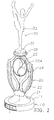
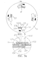
- the modular trophy structure comprises a base body 10 and a label object 20, and the base body 10 comprises a base 11, and the base 11 includes a plurality of rotating latch slots 12 formed thereon, and the plurality of rotating latch slots 12 are formed at positions of the same circumference or different circumferences of the same center.
- the base 11 includes four rotating latch slots 12 formed thereon and arranged at positions of the same circumference
- the rotating latch slot 12 includes a containing slot 121 and a rotating latch slot 122 coupled to (or interconnected with) each other
- the containing slot 121 is coupled to a side of the rotating latch slot 122 in the same circumferential direction
- the other side of the containing slot 121 is protruded farther towards the outside (with respect to the center position) than the rotating latch slot 122, so that an outer side of the rotating latch slot 122 has a blocking portion 123 formed at a position adjacent to the containing slot 121, and the bottom of the blocking portion 123 is a rotating space 124 (as shown in FIG.
- an end of the rotating latch slot 122 away from the containing slot 121 is a rotating latch end 122A.
- the rotating latch slot 122 is tapered towards the rotating latch end 122A.
- the rotating latch end 122A has a width smaller than the rotating latch slot 122.
- the label object 20 includes a label base 21 and a figure body 22 coupled to each other, and the bottom of the label base 21 includes a plurality of rotating latch members 23 disposed at the same circumference or different circumferences of the same center.
- the label base 21 includes four rotating latch members 23 corresponsive to the rotating latch slots 122 of the bases 11, and the four rotating latch members 23 are disposed at positions of the same circumference.
- the rotating latch member 23 includes a disposing portion 231 and a rotating latch portion 232 coupled to each other, and the disposing portion 231 is coupled to a side of the rotating latch portion 232 in the same circumferential direction, and the other side of the disposing portion 231 is protruded farther towards the outside (with respect to the center position) than the rotating latch portion 232.
- the plurality of rotating latch slots 12 of the base 11 and the plurality of rotating latch members 23 of the label base 21 constitute a rotating latch mechanism (not labeled).
- the rotating latch mechanism is installed between the base 11 and the label base 21, and the rotating latch mechanism comprises a rotating latch slot 12 and a rotating latch member 23.
- the spatial positions of the rotating latch slot 12 and the rotating latch member 23 may be switched.
- the base 11 includes the rotating latch member
- the label base 21 includes the rotating slot, but the invention is not limited to such arrangement.
- the containing slot 121 has a width A
- the rotating latch slot 122 has a width B
- the disposing portion 231 has a width a
- the rotating latch portion 232 has a width b
- the width A is equal to or slightly greater than the width a
- the width B is equal to or slightly greater than the width b to facilitate manufacturers or users to install the rotating latch member 23 into the rotating latch slot 12.
- the rotating latch slot 122 has a length greater than the length of the rotating latch portion 232, so as to provide an operating space of moving the rotating latch portion 232 in the rotating latch slot 122.
- the corresponding rotating latch slots 12 and rotating latch members 23 are arranged at positions of the same circumference (with respect to the same center), so that the containing slot 121, rotating latch slot 122 is disposed opposite to the disposing portion 231 and the rotating latch portion 232, and the plurality of rotating latch slots 12 (or rotating latch members 23) are arranged at different circumferences, so as to provide a foolproof effect for the assembling and operation processes.
- the rotating latch member 23 is installed at the rotating latch slot 12, so that the disposing portion 231 (with the width a) is installed into the containing slot 121 (with the width A), and then the rotating latch portion 232 is rotated to move in a direction towards the rotating latch end 122A of the rotating latch slot 122, until a latching effect is produced, and the disposing portion 231 is linked to move into the rotating space 124.
- the rotation and latching effect of the rotating latch mechanism makes the label base 21 to be combined with the base 11, so as to prevent the installation from being dislocated or skewed. If it is necessary to remove or separate the label base 21 from the base 11, the rotating latch portion 232 is rotated in the opposite direction to resume the disposing portion 231 to its original position opposite to the containing slot 121. Now, the label base 21 can be separated or removed from the base 11.
- the assembling and removing operations are quick, simple, and easy.
- the figure body 22 is the main eye-catching area of the trophy, and the figure body 22 may further include at least a label connecting portion 24 and at least a label connector 25 coupled to the label connecting portion 24, and a label rotary latch mechanism (not labeled) may also be installed between the label connecting portion 24 and the label connector 25.
- the label rotary latch mechanism includes a plurality of rotating latch slots 241 installed at the label connecting portion 24 and a plurality of rotating latch members 251 installed at the label connector 25, and the plurality of rotating latch slots 241 and the plurality of rotating latch members 251 are also arranged at the same circumference or different circumferences of the same center, and the rotating latch slot 241 includes a containing slot 242 and a rotating slot 243 coupled to (or interconnected with) each other, and the rotating latch member 251 includes a disposing portion 252 and a rotating latch portion 253 coupled to each other.
- a label rotary latch mechanism is installed between the label connecting portion 24 and the label connector 25, which is the similar to the rotating latch mechanism installed between the base 11 and the label base 21.
- the assembly, operating method or spatial position of the label rotary latch mechanism and the rotating latch mechanism are the same, and thus will not be repeated.
- the label connector 25 shows a label content 254 of the trophy at the front side of the trophy, so that the content of the trophy may be changed if needed.
- the top of the figure body 22 further includes an expansion connecting portion 26, and at least one expansion member 30 is coupled to the expansion connecting portion 26, and the expansion member 30 includes an expanded base 31 and an expanded figure body 32, and an expanded rotating latch mechanism (not labeled) is also installed between the expanded base 31 and the expansion connecting portion 26.
- the expanded rotating latch mechanism includes a plurality of rotating slots (not shown in the figure) formed at the expansion connecting portion 26 and a plurality of rotating latch members 311 installed at the expanded base 31, and an expanded rotating latch mechanism installed between the expanded base 31 and the expansion connecting portion 26 is the same as the rotating latch mechanism installed between the base 11 and the label base 21.
- the expanded figure body 32 of the expansion member 30 is another expanded area for showing the content of the trophy.
- the expansion member 30 acts as an end connecting member (not shown in the figure), and the expanded rotating latch mechanism installed between the end connecting member and the expansion connecting portion 26 may be reserved for connecting or replacing the expansion member 30 at a later time.
- the top of the expanded figure body 32 may have another expanded rotating latch mechanism (not shown in the figure) coupled to an expansion member, so that the content and height of the label of the trophy may be increased as required to provide a flexible assembling and manufacturing processes of the trophy.
- the bottom of the blocking portion 123 of the base 11 further includes at least one concave latch portion 125
- the top of the disposing portion 231 includes at least one convex latch portion 233
- the concave latch portion 125 and the convex latch portion 233 are latched with each other, and they may be in form of one or more pairs.
- the convex latch portion 233 is precisely latched to the concave latch portion 125 to provide better latching and positioning effects and enhance the feel of positioning during the rotation and combining operation.
- the spatial positions of the concave latch portion 125 and the convex latch portion 233 may be switched.
- the concave latch portion 125 is disposed at the top of the disposing portion 231, and the convex latch portion 233 is disposed at the bottom of the blocking portion 123.
- a label rotary latch mechanism is installed between the label connecting portion 24 and the label connector 25, and an expanded rotating latch mechanism is installed between the expanded base 31 and the expansion connecting portion 26.
- Such arrangements are applicable for latching the concave latch portion 125 with the convex latch portion 233.
- the relative positions of the base 11 and the label base 21 are positioned and combined, wherein the base 11 has a positioning recess 13, and the label base 21 has a positioning protrusion member 27 which can be positioned and latched to the positioning recess 13 by rotating, combining and operating the label base 21, so as to provide better latching and positioning effects of positioning, combining and operating the base 11 with the label base 21 and enhance the positioning feel of the rotation and combining operation.
- the modular trophy structure of the present invention provides a more convenient and quicker way of assembling the trophy to provide a cost-effective manufacture.
- the present invention features various way of combining the components of the trophy to provide flexible applications of the trophy to improve the applicability, practicality and value of the trophy.
- the present invention further has the effect of preventing the assembling and manufacture of the trophy from being dislocated or skewed, so as to improve the overall assembling quality and the display quality of the trophy.
Landscapes
- Packages (AREA)
Priority Applications (1)
| Application Number | Priority Date | Filing Date | Title |
|---|---|---|---|
| EP14002918.2A EP2987431A1 (fr) | 2014-08-22 | 2014-08-22 | Structure de trophée modulaire |
Applications Claiming Priority (1)
| Application Number | Priority Date | Filing Date | Title |
|---|---|---|---|
| EP14002918.2A EP2987431A1 (fr) | 2014-08-22 | 2014-08-22 | Structure de trophée modulaire |
Publications (1)
| Publication Number | Publication Date |
|---|---|
| EP2987431A1 true EP2987431A1 (fr) | 2016-02-24 |
Family
ID=51399500
Family Applications (1)
| Application Number | Title | Priority Date | Filing Date |
|---|---|---|---|
| EP14002918.2A Withdrawn EP2987431A1 (fr) | 2014-08-22 | 2014-08-22 | Structure de trophée modulaire |
Country Status (1)
| Country | Link |
|---|---|
| EP (1) | EP2987431A1 (fr) |
Cited By (1)
| Publication number | Priority date | Publication date | Assignee | Title |
|---|---|---|---|---|
| WO2020183112A1 (fr) | 2019-03-12 | 2020-09-17 | Cyano-3D | Objet decoratif de type trophee personnalisable |
Citations (3)
| Publication number | Priority date | Publication date | Assignee | Title |
|---|---|---|---|---|
| US20090146025A1 (en) * | 2007-12-07 | 2009-06-11 | William Steven Schwartz Revocable Trust | Trophy Assembly With Twist Connector |
| US20100213087A1 (en) * | 2009-02-25 | 2010-08-26 | Weldon John T | Ball display case |
| US20110183150A1 (en) * | 2010-01-27 | 2011-07-28 | Simply Awards LLC | Trophy column for interchangeable display of design elements |
-
2014
- 2014-08-22 EP EP14002918.2A patent/EP2987431A1/fr not_active Withdrawn
Patent Citations (3)
| Publication number | Priority date | Publication date | Assignee | Title |
|---|---|---|---|---|
| US20090146025A1 (en) * | 2007-12-07 | 2009-06-11 | William Steven Schwartz Revocable Trust | Trophy Assembly With Twist Connector |
| US20100213087A1 (en) * | 2009-02-25 | 2010-08-26 | Weldon John T | Ball display case |
| US20110183150A1 (en) * | 2010-01-27 | 2011-07-28 | Simply Awards LLC | Trophy column for interchangeable display of design elements |
Cited By (2)
| Publication number | Priority date | Publication date | Assignee | Title |
|---|---|---|---|---|
| WO2020183112A1 (fr) | 2019-03-12 | 2020-09-17 | Cyano-3D | Objet decoratif de type trophee personnalisable |
| FR3093628A1 (fr) | 2019-03-12 | 2020-09-18 | Cyano-3D | Objet decoratif de type trophee personnalisable |
Similar Documents
| Publication | Publication Date | Title |
|---|---|---|
| US20160058228A1 (en) | Modular trophy structure | |
| US20170002853A1 (en) | Fastener for securing a panel on a support | |
| KR101706379B1 (ko) | 이탈 방지 에어 포일 저널 베어링 | |
| US9688251B2 (en) | Wiper connector and bolt-stabilizing sleeve adaptor | |
| JP6692818B2 (ja) | バスバーを収容するための改良された構造を有する火工式回路遮断器およびその組立方法 | |
| US20080169719A1 (en) | Motor magnet fixing device | |
| US9234536B2 (en) | Receptacle for fasteners and an associated installation method | |
| US12019810B2 (en) | Keyboard assembly | |
| EP3180524B1 (fr) | Goujon et manchon de verrouillage par insertion et procédés associés | |
| US10971880B2 (en) | Connection for printed circuit board assemblies | |
| KR20180125772A (ko) | 오조립 방지 에어 포일 저널 베어링 | |
| KR101887834B1 (ko) | 전기 커넥터 | |
| EP2987431A1 (fr) | Structure de trophée modulaire | |
| US20170066123A1 (en) | Display board for tool | |
| KR102827486B1 (ko) | 드라이버 에어백 모듈 결합 조립체 | |
| CN106102851A (zh) | 模型 | |
| US20090056075A1 (en) | Hinge With Locking Tab | |
| US20200362894A1 (en) | Connector | |
| US20200132095A1 (en) | Fool-proof housing | |
| KR101864365B1 (ko) | 블록형 가구 | |
| US12060905B2 (en) | Fasteners | |
| JP6447452B2 (ja) | 基板用コネクタ | |
| JP2015200621A (ja) | プローブカバー | |
| KR20110002798U (ko) | 너트 | |
| CN114929070A (zh) | 用于家具的调节装置和组装调节装置的方法 |
Legal Events
| Date | Code | Title | Description |
|---|---|---|---|
| PUAI | Public reference made under article 153(3) epc to a published international application that has entered the european phase |
Free format text: ORIGINAL CODE: 0009012 |
|
| AK | Designated contracting states |
Kind code of ref document: A1 Designated state(s): AL AT BE BG CH CY CZ DE DK EE ES FI FR GB GR HR HU IE IS IT LI LT LU LV MC MK MT NL NO PL PT RO RS SE SI SK SM TR |
|
| AX | Request for extension of the european patent |
Extension state: BA ME |
|
| STAA | Information on the status of an ep patent application or granted ep patent |
Free format text: STATUS: THE APPLICATION IS DEEMED TO BE WITHDRAWN |
|
| 18D | Application deemed to be withdrawn |
Effective date: 20160825 |